US5323860A - Apparatus for connecting a diverter assembly to a blowout preventer stack - Google Patents
Apparatus for connecting a diverter assembly to a blowout preventer stackDownload PDFInfo
- Publication number
- US5323860A US5323860AUS07/984,465US98446592AUS5323860AUS 5323860 AUS5323860 AUS 5323860AUS 98446592 AUS98446592 AUS 98446592AUS 5323860 AUS5323860 AUS 5323860A
- Authority
- US
- United States
- Prior art keywords
- tubular
- tubular body
- packing
- spherical surface
- bore
- Prior art date
- Legal status (The legal status is an assumption and is not a legal conclusion. Google has not performed a legal analysis and makes no representation as to the accuracy of the status listed.)
- Expired - Lifetime
Links
Images

Classifications
- F—MECHANICAL ENGINEERING; LIGHTING; HEATING; WEAPONS; BLASTING
- F16—ENGINEERING ELEMENTS AND UNITS; GENERAL MEASURES FOR PRODUCING AND MAINTAINING EFFECTIVE FUNCTIONING OF MACHINES OR INSTALLATIONS; THERMAL INSULATION IN GENERAL
- F16L—PIPES; JOINTS OR FITTINGS FOR PIPES; SUPPORTS FOR PIPES, CABLES OR PROTECTIVE TUBING; MEANS FOR THERMAL INSULATION IN GENERAL
- F16L27/00—Adjustable joints; Joints allowing movement
- F16L27/02—Universal joints, i.e. with mechanical connection allowing angular movement or adjustment of the axes of the parts in any direction
- F16L27/04—Universal joints, i.e. with mechanical connection allowing angular movement or adjustment of the axes of the parts in any direction with partly-spherical engaging surfaces
- E—FIXED CONSTRUCTIONS
- E21—EARTH OR ROCK DRILLING; MINING
- E21B—EARTH OR ROCK DRILLING; OBTAINING OIL, GAS, WATER, SOLUBLE OR MELTABLE MATERIALS OR A SLURRY OF MINERALS FROM WELLS
- E21B33/00—Sealing or packing boreholes or wells
- E21B33/02—Surface sealing or packing
- E21B33/03—Well heads; Setting-up thereof
- E21B33/035—Well heads; Setting-up thereof specially adapted for underwater installations
- E21B33/038—Connectors used on well heads, e.g. for connecting blow-out preventer and riser
- F—MECHANICAL ENGINEERING; LIGHTING; HEATING; WEAPONS; BLASTING
- F16—ENGINEERING ELEMENTS AND UNITS; GENERAL MEASURES FOR PRODUCING AND MAINTAINING EFFECTIVE FUNCTIONING OF MACHINES OR INSTALLATIONS; THERMAL INSULATION IN GENERAL
- F16L—PIPES; JOINTS OR FITTINGS FOR PIPES; SUPPORTS FOR PIPES, CABLES OR PROTECTIVE TUBING; MEANS FOR THERMAL INSULATION IN GENERAL
- F16L27/00—Adjustable joints; Joints allowing movement
- F16L27/12—Adjustable joints; Joints allowing movement allowing substantial longitudinal adjustment or movement
- F16L27/127—Adjustable joints; Joints allowing movement allowing substantial longitudinal adjustment or movement with means for locking the longitudinal adjustment or movement in the final mounted position
- E—FIXED CONSTRUCTIONS
- E21—EARTH OR ROCK DRILLING; MINING
- E21B—EARTH OR ROCK DRILLING; OBTAINING OIL, GAS, WATER, SOLUBLE OR MELTABLE MATERIALS OR A SLURRY OF MINERALS FROM WELLS
- E21B21/00—Methods or apparatus for flushing boreholes, e.g. by use of exhaust air from motor
- E21B21/001—Methods or apparatus for flushing boreholes, e.g. by use of exhaust air from motor specially adapted for underwater drilling
Definitions
- diverter systemsThe purpose of so-called diverter systems is to provide low pressure control over the well during the preliminary stages of drilling, and, for this purpose, the system includes a housing supported with its bore beneath the rotary table on the platform and having one or more side outlets from the bore for connection with drilling mud return lines on the platform.
- a diverter assemblycomprising a tubular body adapted to be lowered into a supported position in the bore of the housing has a port aligned with each side outlet from the bore, and a spool having packing at its lower end is suspended from the body for lowering over the upper end of a conductor extending upwardly from the preventer stack as the body is landed in the bore of the housing.
- the tubular bodycarries means which seals between it and the housing bore to confine flow within the body into the side outlets with flow normally returning to the rig mud system from which it may be recirculated into the drill string.
- Packersare adapted to be lowered into and landed in the diverter body to seal about a drill string extending downwardly from the rotary table and through the tubular body leading to the conductor, whereby the drilling fluid returns about the string can be "diverted" into overboard lines connected to the outlets in the housing with reservoirs on the platform.
- the first spherical surfacemay rotate within the first packing and the second packing may rotate about the second spherical surface to permit the tubular body to be swung into tilted positions with respect to the axes of the bores, and the tubular body is suspended from the upper tubular member so that the second packing on the lower end of the tubular body may be lowered onto or raised from the lower tubular member regardless of the misalignment of the bores.
- the packingsare inflatable into tight sealing engagement with the spherical surfaces.
- the tubular bodyincludes an upper tubular section suspended from the upper tubular member and having the first spherical surface rotatable about the first packing, a lower tubular section longitudinally slidable with respect to the lower section and having the second packing carried about its lower end for rotation about the second spherical surface, and packing means carried about the outer of the tubular sections to form a sliding seal about the inner tubular section and also preferably inflatable into tight sealing engagement therewith.
- extendable and retractible actuators spaced about the tubular bodyare connected to the upper and lower tubular sections, and a means is provided for selectively extending and retracting the actuators so as to control the direction and degree of tilt of the tubular body.
- the actuatorsmay be extended and retracted as a group to install or remove the second packing, and selectively extended and retracted so as to swing the tubular body into tilted positions necessary to accommodate the misalignment.
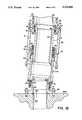
- FIGS. 1A and 1Bare vertical sectional views of connecting apparatus constructed in accordance with the present invention and showing, in FIG. 1A, its upper end connected to a diverter assembly, and, in FIG. 1B, its lower end connected to a blowout-preventer stack.
- the diverter system shown in FIG. 1Aincludes a housing 11 having a bore 12 therethrough and adapted to be supported in a manner well-known in the art beneath the rotary table of the platform on which the drilling rig is mounted.
- the housinghas side outlet 13 connecting with the bore and adapted to have a flow line (not shown) for returning drilling mud to a resevoir on the platform, as well as a side outlet 13A connecting with the bore and adapted to have an overboard line (not shown) connected thereto for "diverting" when required.
- the diverter system 10also includes a tubular body 14 having a bore 15 therethrough and a shoulder 16 thereabout for supporting it on a seat 17 within the bore 12 of the housing. More particularly, the tubular body has openings 18 therethrough for connecting the bore 15 with the side outlets 13 and 13A, and carries seals 19 and 20 thereabout above and below the openings of 18 for confining flow through the outlets 18 and 18A to the side outlets 13 and 13A.
- the systemalso includes a packer assembly 21 removably disposable within an inwardly inflatable packer 22 carried within the upper end of the bore 15 of the tubular body.
- the inner diameter of the assembly 21is adapted to receive drill pipe or casing extending through the diverter assembly and into the well bore there-below, and is adapted to be forced inwardly to seal about the drill pipe by inflation of the packing 22 through fluid supply through ports 23.
- the tubular bodyis latched within the bore of the housing 11, and the packing assembly 21 is latched within the bore of the tubular body opposite the packing assembly 22.
- the apparatus for connecting the boresalso includes an intermediate tubular body 31 extending between the upper and lower tubular members 25 and 28. More particularly, the upper end of the tubular body 31 has a first spherical surface 32 thereabout for fitting within a first packing 33 within the lower end of the first tubular member 35 so as to permit the upper end of the tubular body 31 to swing about the horizontal axis of the spherical surface 32.
- the upper end of the tubular body 31is supported from the lower end of the tubular member 25 by means of a ring 34 on the lower end of the tubular member 25 beneath the packing 33 and having an inner diameter less than the diameter of the spherical surface 32.
- the ringis removably connected to an enlarged diameter lower end of the tubular body 25 to form a recess above it in which the packing assembly 33 is mounted.
- the packing 33is preferably inwardly inflatable into tight sealing engagement with the spherical surface 32.
- the packing 33includes an annular sleeve 35 of elastomeric material carried by upper and lower rings disposed within the recess so that the sleeve may be inwardly inflated by fluid pressure supplied to the recess through ports 37 to which flexible hoses or other conduits (not shown) may be connected.
- the upper end of the lower tubular member 28has a second spherical surface 38 thereabout and disposed within a second packing 39 carried within the lower end of the tubular body 31 for sealing engagement therewith.
- the packing 39preferably comprises an annular sleeve 40 of elastomeric material carried by upper and lower rings 41 sealably disposed within the recess.
- Fluid pressuremay also be supplied to the outer side of the sleeve to cause it to tightly engage about the spherical surface 38 through ports 42 formed in the lower end of the tubular body.
- Hoses or other flexible conduitsmay be connected for supplying fluid pressure to the sleeve in the same source as to that supplying pressure to the sleeve 35.
- the tubular body 31is made up of upper and lower tubular sections 43 and 44 which are arranged telescopically for sliding longitudinally with respect to one another.
- the upper tubular section 43carries the spherical surface 32 at its upper end while the lower tubular section 44 carries the sleeve 39 about its lower end.
- a third packing 45is carried within the upper end of the lower tubular section of 44 to form a sliding seal with the upper tubular section 43 above an enlargement 46 at its lower end which is guidably slidable within the lower tubular section 44 beneath the packing assembly.
- the assembly 45preferably includes an inwardly inflatible sleeve 47 of elastomeric material carried by upper and lower rings 48 and 49 received within a recess within the upper end of section 44.
- the sleeveis inwardly inflatible by means of fluid pressure applied through ports 50 from a remote source, as in the case of the other packing assemblies.
- the tubular bodyis extendable and contractable by means of fluid actuators 51 (usually four) each pivotally connected at its upper end to the upper tubular member 25 and its lower end to the lower tubular section 44 of the tubular body.
- fluid actuators 51usually four
- retraction of the actuator 51raises the lower end of the lower tubular section 44 to permit it to be lowered on to or lifted from the upper end of the lower tubular member, while extension of the actuators permits the lower end of the tubular 44 to be lowered over the upper end of the lower tubular body 28.
- Fluidmay be supplied to opposite sides of the pistons (not shown) of the cylinders of the actuators from any suitable source, as described above in connection with the inwardly inflatible packing assemblies.
- the actuators 51are selectively operable so as to permit one of them to be extended while the other is retracted in order to swing the tubular body about the axis of the upper spherical surface 32.
- the left-hand actuator 51may be retracted as the right-hand actuator 51 is extended so as to swing the tubular body in a clockwise direction in order to bring the lower end of the tubular section 44 into position for lowering over the upper end of the lower tubular member 28 when the blowout preventer stack is misaligned to the left of the diverter system.
Landscapes
- Engineering & Computer Science (AREA)
- General Engineering & Computer Science (AREA)
- Mechanical Engineering (AREA)
- Life Sciences & Earth Sciences (AREA)
- Geology (AREA)
- Mining & Mineral Resources (AREA)
- Physics & Mathematics (AREA)
- Environmental & Geological Engineering (AREA)
- Fluid Mechanics (AREA)
- General Life Sciences & Earth Sciences (AREA)
- Geochemistry & Mineralogy (AREA)
- Earth Drilling (AREA)
Abstract
Description
Claims (5)
Priority Applications (3)
| Application Number | Priority Date | Filing Date | Title |
|---|---|---|---|
| US07/984,465US5323860A (en) | 1992-12-02 | 1992-12-02 | Apparatus for connecting a diverter assembly to a blowout preventer stack |
| SG1995001879ASG41953A1 (en) | 1992-12-02 | 1993-03-10 | Apparatus for connecting a diverter to a blowout preventer stack |
| GB9304899AGB2273119B (en) | 1992-12-02 | 1993-03-10 | Apparatus for connecting a diverter assembly to a blowout preventer stack |
Applications Claiming Priority (1)
| Application Number | Priority Date | Filing Date | Title |
|---|---|---|---|
| US07/984,465US5323860A (en) | 1992-12-02 | 1992-12-02 | Apparatus for connecting a diverter assembly to a blowout preventer stack |
Publications (1)
| Publication Number | Publication Date |
|---|---|
| US5323860Atrue US5323860A (en) | 1994-06-28 |
Family
ID=25530585
Family Applications (1)
| Application Number | Title | Priority Date | Filing Date |
|---|---|---|---|
| US07/984,465Expired - LifetimeUS5323860A (en) | 1992-12-02 | 1992-12-02 | Apparatus for connecting a diverter assembly to a blowout preventer stack |
Country Status (3)
| Country | Link |
|---|---|
| US (1) | US5323860A (en) |
| GB (1) | GB2273119B (en) |
| SG (1) | SG41953A1 (en) |
Cited By (8)
| Publication number | Priority date | Publication date | Assignee | Title |
|---|---|---|---|---|
| US5887659A (en)* | 1997-05-14 | 1999-03-30 | Dril-Quip, Inc. | Riser for use in drilling or completing a subsea well |
| EP0913615A4 (en)* | 1996-06-11 | 1999-08-25 | Victaulic Japan | Flexible expansion joint |
| US8720580B1 (en) | 2011-06-14 | 2014-05-13 | Trendsetter Engineering, Inc. | System and method for diverting fluids from a damaged blowout preventer |
| US8752637B1 (en)* | 2013-08-16 | 2014-06-17 | Energy System Nevada, Llc | Extendable conductor stand and method of use |
| US9033051B1 (en) | 2011-06-14 | 2015-05-19 | Trendsetter Engineering, Inc. | System for diversion of fluid flow from a wellhead |
| US9045959B1 (en) | 2012-09-21 | 2015-06-02 | Trendsetter Engineering, Inc. | Insert tube for use with a lower marine riser package |
| US9080411B1 (en) | 2011-06-14 | 2015-07-14 | Trendsetter Engineering, Inc. | Subsea diverter system for use with a blowout preventer |
| US9670755B1 (en) | 2011-06-14 | 2017-06-06 | Trendsetter Engineering, Inc. | Pump module systems for preventing or reducing release of hydrocarbons from a subsea formation |
Families Citing this family (1)
| Publication number | Priority date | Publication date | Assignee | Title |
|---|---|---|---|---|
| WO2012076703A2 (en) | 2010-12-10 | 2012-06-14 | Statoil Petroleum As | Riser coupling |
Citations (11)
| Publication number | Priority date | Publication date | Assignee | Title |
|---|---|---|---|---|
| US3450421A (en)* | 1966-06-20 | 1969-06-17 | Gray Tool Co | Ball connector |
| US3601187A (en)* | 1969-05-02 | 1971-08-24 | Exxon Production Research Co | Drilling riser |
| US3782458A (en)* | 1971-08-04 | 1974-01-01 | Gray Tool Co | Upright, swivelable buoyed conduit for offshore system |
| US3791442A (en)* | 1971-09-28 | 1974-02-12 | Regan Forge & Eng Co | Coupling means for a riser string run from a floating vessel to a subsea well |
| US4153112A (en)* | 1977-07-01 | 1979-05-08 | Cameron Iron Works, Inc. | Flex joint |
| US4428433A (en)* | 1981-09-28 | 1984-01-31 | Hughes Tool Company | Telescopic joint upper tube retainer method |
| GB2150614A (en)* | 1983-11-30 | 1985-07-03 | Hydril Co | Diverter/bop system & method for a bottom supported offshore drilling rig |
| US4557332A (en)* | 1984-04-09 | 1985-12-10 | Shell Offshore Inc. | Drilling riser locking apparatus and method |
| US4640372A (en)* | 1985-11-25 | 1987-02-03 | Davis Haggai D | Diverter including apparatus for breaking up large pieces of formation carried to the surface by the drilling mud |
| US4646844A (en)* | 1984-12-24 | 1987-03-03 | Hydril Company | Diverter/bop system and method for a bottom supported offshore drilling rig |
| US5167283A (en)* | 1991-12-20 | 1992-12-01 | Abb Vetco Gray Inc. | Combination ball valve and annular pipe seal |
- 1992
- 1992-12-02USUS07/984,465patent/US5323860A/ennot_activeExpired - Lifetime
- 1993
- 1993-03-10SGSG1995001879Apatent/SG41953A1/enunknown
- 1993-03-10GBGB9304899Apatent/GB2273119B/ennot_activeExpired - Fee Related
Patent Citations (11)
| Publication number | Priority date | Publication date | Assignee | Title |
|---|---|---|---|---|
| US3450421A (en)* | 1966-06-20 | 1969-06-17 | Gray Tool Co | Ball connector |
| US3601187A (en)* | 1969-05-02 | 1971-08-24 | Exxon Production Research Co | Drilling riser |
| US3782458A (en)* | 1971-08-04 | 1974-01-01 | Gray Tool Co | Upright, swivelable buoyed conduit for offshore system |
| US3791442A (en)* | 1971-09-28 | 1974-02-12 | Regan Forge & Eng Co | Coupling means for a riser string run from a floating vessel to a subsea well |
| US4153112A (en)* | 1977-07-01 | 1979-05-08 | Cameron Iron Works, Inc. | Flex joint |
| US4428433A (en)* | 1981-09-28 | 1984-01-31 | Hughes Tool Company | Telescopic joint upper tube retainer method |
| GB2150614A (en)* | 1983-11-30 | 1985-07-03 | Hydril Co | Diverter/bop system & method for a bottom supported offshore drilling rig |
| US4557332A (en)* | 1984-04-09 | 1985-12-10 | Shell Offshore Inc. | Drilling riser locking apparatus and method |
| US4646844A (en)* | 1984-12-24 | 1987-03-03 | Hydril Company | Diverter/bop system and method for a bottom supported offshore drilling rig |
| US4640372A (en)* | 1985-11-25 | 1987-02-03 | Davis Haggai D | Diverter including apparatus for breaking up large pieces of formation carried to the surface by the drilling mud |
| US5167283A (en)* | 1991-12-20 | 1992-12-01 | Abb Vetco Gray Inc. | Combination ball valve and annular pipe seal |
Non-Patent Citations (2)
| Title |
|---|
| Pages 25 and 27 of 1986 87 Hughes Offshore General Catalog.* |
| Pages 25 and 27 of 1986-87 Hughes Offshore General Catalog. |
Cited By (8)
| Publication number | Priority date | Publication date | Assignee | Title |
|---|---|---|---|---|
| EP0913615A4 (en)* | 1996-06-11 | 1999-08-25 | Victaulic Japan | Flexible expansion joint |
| US5887659A (en)* | 1997-05-14 | 1999-03-30 | Dril-Quip, Inc. | Riser for use in drilling or completing a subsea well |
| US8720580B1 (en) | 2011-06-14 | 2014-05-13 | Trendsetter Engineering, Inc. | System and method for diverting fluids from a damaged blowout preventer |
| US9033051B1 (en) | 2011-06-14 | 2015-05-19 | Trendsetter Engineering, Inc. | System for diversion of fluid flow from a wellhead |
| US9080411B1 (en) | 2011-06-14 | 2015-07-14 | Trendsetter Engineering, Inc. | Subsea diverter system for use with a blowout preventer |
| US9670755B1 (en) | 2011-06-14 | 2017-06-06 | Trendsetter Engineering, Inc. | Pump module systems for preventing or reducing release of hydrocarbons from a subsea formation |
| US9045959B1 (en) | 2012-09-21 | 2015-06-02 | Trendsetter Engineering, Inc. | Insert tube for use with a lower marine riser package |
| US8752637B1 (en)* | 2013-08-16 | 2014-06-17 | Energy System Nevada, Llc | Extendable conductor stand and method of use |
Also Published As
| Publication number | Publication date |
|---|---|
| GB9304899D0 (en) | 1993-04-28 |
| GB2273119B (en) | 1996-03-20 |
| GB2273119A (en) | 1994-06-08 |
| SG41953A1 (en) | 1997-08-15 |
Similar Documents
| Publication | Publication Date | Title |
|---|---|---|
| US10309181B2 (en) | Riser fluid handling system | |
| US3710859A (en) | Apparatus for remotely connecting and disconnecting pipe lines to and from a submerged wellhead | |
| US3741296A (en) | Replacement of sub sea blow out preventer packing units | |
| US8689880B2 (en) | Multipart sliding joint for floating rig | |
| US5706893A (en) | Tubing hanger | |
| US5727630A (en) | Telescopic joint control line system | |
| US6109352A (en) | Simplified Xmas tree using sub-sea test tree | |
| GB2170534A (en) | Upper marine riser package | |
| GB2371318A (en) | Inserting or removing a string of tubulars from a subsea borehole | |
| US5323860A (en) | Apparatus for connecting a diverter assembly to a blowout preventer stack | |
| US11873695B2 (en) | Blowout preventer apparatus and method | |
| US8960303B2 (en) | Gooseneck conduit system | |
| NO345357B1 (en) | A heave compensating system for a floating drilling vessel | |
| OA13057A (en) | Annulus monitoring system. | |
| US7377323B2 (en) | Blowout preventer stack landing assist tool | |
| US3251611A (en) | Wellhead connector | |
| WO2014120130A1 (en) | Riser fluid handling system | |
| US5211228A (en) | Diverter system | |
| US11993987B2 (en) | Gooseneck connector system | |
| CA1239091A (en) | Blowout preventer valve and bop stack | |
| US20250075580A1 (en) | Riser-less managed pressure operations | |
| NO347890B1 (en) | An apparatus, a system, and a method for umbilical-less installation and operation of a tubing hanger | |
| WO2002088515A1 (en) | Offshore delivery line support | |
| KR20000010926A (en) | Slip joint |
Legal Events
| Date | Code | Title | Description |
|---|---|---|---|
| AS | Assignment | Owner name:DRIL-QUIP, INC., TEXAS Free format text:ASSIGNMENT OF ASSIGNORS INTEREST.;ASSIGNOR:WATKINS, BRUCE J.;REEL/FRAME:006346/0019 Effective date:19921120 | |
| STCF | Information on status: patent grant | Free format text:PATENTED CASE | |
| FEPP | Fee payment procedure | Free format text:PAT HOLDER CLAIMS SMALL ENTITY STATUS - SMALL BUSINESS (ORIGINAL EVENT CODE: SM02); ENTITY STATUS OF PATENT OWNER: LARGE ENTITY Free format text:PAT HLDR NO LONGER CLAIMS SMALL ENT STAT AS SMALL BUSINESS (ORIGINAL EVENT CODE: LSM2); ENTITY STATUS OF PATENT OWNER: LARGE ENTITY Free format text:PAYOR NUMBER ASSIGNED (ORIGINAL EVENT CODE: ASPN); ENTITY STATUS OF PATENT OWNER: LARGE ENTITY | |
| FPAY | Fee payment | Year of fee payment:4 | |
| FEPP | Fee payment procedure | Free format text:PAYER NUMBER DE-ASSIGNED (ORIGINAL EVENT CODE: RMPN); ENTITY STATUS OF PATENT OWNER: LARGE ENTITY Free format text:PAYOR NUMBER ASSIGNED (ORIGINAL EVENT CODE: ASPN); ENTITY STATUS OF PATENT OWNER: LARGE ENTITY | |
| FEPP | Fee payment procedure | Free format text:PAT HOLDER NO LONGER CLAIMS SMALL ENTITY STATUS, ENTITY STATUS SET TO UNDISCOUNTED (ORIGINAL EVENT CODE: STOL); ENTITY STATUS OF PATENT OWNER: LARGE ENTITY | |
| FEPP | Fee payment procedure | Free format text:PAYER NUMBER DE-ASSIGNED (ORIGINAL EVENT CODE: RMPN); ENTITY STATUS OF PATENT OWNER: LARGE ENTITY Free format text:PAYOR NUMBER ASSIGNED (ORIGINAL EVENT CODE: ASPN); ENTITY STATUS OF PATENT OWNER: LARGE ENTITY | |
| FPAY | Fee payment | Year of fee payment:8 | |
| REMI | Maintenance fee reminder mailed | ||
| FPAY | Fee payment | Year of fee payment:12 |