US5322477A - Downsized cushioning dunnage conversion machine and packaging systems employing the same - Google Patents
Downsized cushioning dunnage conversion machine and packaging systems employing the sameDownload PDFInfo
- Publication number
- US5322477A US5322477AUS07/592,572US59257290AUS5322477AUS 5322477 AUS5322477 AUS 5322477AUS 59257290 AUS59257290 AUS 59257290AUS 5322477 AUS5322477 AUS 5322477A
- Authority
- US
- United States
- Prior art keywords
- assembly
- frame
- downstream
- end plate
- strip
- Prior art date
- Legal status (The legal status is an assumption and is not a legal conclusion. Google has not performed a legal analysis and makes no representation as to the accuracy of the status listed.)
- Expired - Fee Related
Links
- 238000006243chemical reactionMethods0.000titleclaimsabstractdescription45
- 238000004806packaging method and processMethods0.000titledescription56
- 239000000463materialSubstances0.000claimsabstractdescription97
- 238000005520cutting processMethods0.000claimsabstractdescription90
- 238000011144upstream manufacturingMethods0.000claimsabstractdescription71
- 238000007493shaping processMethods0.000claimsdescription14
- 238000005096rolling processMethods0.000claimsdescription10
- 229910052782aluminiumInorganic materials0.000claimsdescription4
- XAGFODPZIPBFFR-UHFFFAOYSA-NaluminiumChemical group[Al]XAGFODPZIPBFFR-UHFFFAOYSA-N0.000claimsdescription4
- 238000000034methodMethods0.000claimsdescription4
- 239000004033plasticSubstances0.000description17
- 239000000123paperSubstances0.000description15
- 230000001681protective effectEffects0.000description14
- 239000005022packaging materialSubstances0.000description13
- 241001553178Arachis glabrataSpecies0.000description6
- 235000020232peanutNutrition0.000description6
- 239000002984plastic foamSubstances0.000description6
- 230000006870functionEffects0.000description5
- 238000012856packingMethods0.000description4
- 230000009471actionEffects0.000description3
- 230000000712assemblyEffects0.000description3
- 238000000429assemblyMethods0.000description3
- 239000003638chemical reducing agentSubstances0.000description3
- 230000007423decreaseEffects0.000description3
- 230000007246mechanismEffects0.000description3
- 239000002245particleSubstances0.000description3
- 238000010008shearingMethods0.000description3
- 230000004075alterationEffects0.000description2
- 239000011248coating agentSubstances0.000description2
- 238000000576coating methodMethods0.000description2
- 230000003247decreasing effectEffects0.000description2
- 239000000428dustSubstances0.000description2
- 230000006872improvementEffects0.000description2
- 238000004519manufacturing processMethods0.000description2
- 230000004048modificationEffects0.000description2
- 238000012986modificationMethods0.000description2
- 230000008569processEffects0.000description2
- 238000004513sizingMethods0.000description2
- 239000003381stabilizerSubstances0.000description2
- 230000003068static effectEffects0.000description2
- 230000007704transitionEffects0.000description2
- 229920001328Polyvinylidene chloridePolymers0.000description1
- 230000008859changeEffects0.000description1
- 230000001066destructive effectEffects0.000description1
- 230000009977dual effectEffects0.000description1
- 230000000694effectsEffects0.000description1
- 230000005611electricityEffects0.000description1
- 230000007613environmental effectEffects0.000description1
- 238000009434installationMethods0.000description1
- 239000002655kraft paperSubstances0.000description1
- 238000012423maintenanceMethods0.000description1
- 229910052751metalInorganic materials0.000description1
- 239000002184metalSubstances0.000description1
- 235000014571nutsNutrition0.000description1
- 239000002985plastic filmSubstances0.000description1
- 229920006255plastic filmPolymers0.000description1
- 239000005033polyvinylidene chlorideSubstances0.000description1
- 230000000750progressive effectEffects0.000description1
- 230000009467reductionEffects0.000description1
- 230000008439repair processEffects0.000description1
- 230000000452restraining effectEffects0.000description1
- 238000000926separation methodMethods0.000description1
- 238000003860storageMethods0.000description1
- 239000002699waste materialSubstances0.000description1
Images


Classifications
- B—PERFORMING OPERATIONS; TRANSPORTING
- B31—MAKING ARTICLES OF PAPER, CARDBOARD OR MATERIAL WORKED IN A MANNER ANALOGOUS TO PAPER; WORKING PAPER, CARDBOARD OR MATERIAL WORKED IN A MANNER ANALOGOUS TO PAPER
- B31D—MAKING ARTICLES OF PAPER, CARDBOARD OR MATERIAL WORKED IN A MANNER ANALOGOUS TO PAPER, NOT PROVIDED FOR IN SUBCLASSES B31B OR B31C
- B31D5/00—Multiple-step processes for making three-dimensional articles ; Making three-dimensional articles
- B31D5/0039—Multiple-step processes for making three-dimensional articles ; Making three-dimensional articles for making dunnage or cushion pads
- B31D5/0043—Multiple-step processes for making three-dimensional articles ; Making three-dimensional articles for making dunnage or cushion pads including crumpling flat material
- B31D5/0047—Multiple-step processes for making three-dimensional articles ; Making three-dimensional articles for making dunnage or cushion pads including crumpling flat material involving toothed wheels
- B—PERFORMING OPERATIONS; TRANSPORTING
- B26—HAND CUTTING TOOLS; CUTTING; SEVERING
- B26D—CUTTING; DETAILS COMMON TO MACHINES FOR PERFORATING, PUNCHING, CUTTING-OUT, STAMPING-OUT OR SEVERING
- B26D1/00—Cutting through work characterised by the nature or movement of the cutting member or particular materials not otherwise provided for; Apparatus or machines therefor; Cutting members therefor
- B26D1/01—Cutting through work characterised by the nature or movement of the cutting member or particular materials not otherwise provided for; Apparatus or machines therefor; Cutting members therefor involving a cutting member which does not travel with the work
- B26D1/12—Cutting through work characterised by the nature or movement of the cutting member or particular materials not otherwise provided for; Apparatus or machines therefor; Cutting members therefor involving a cutting member which does not travel with the work having a cutting member moving about an axis
- B26D1/25—Cutting through work characterised by the nature or movement of the cutting member or particular materials not otherwise provided for; Apparatus or machines therefor; Cutting members therefor involving a cutting member which does not travel with the work having a cutting member moving about an axis with a non-circular cutting member
- B26D1/26—Cutting through work characterised by the nature or movement of the cutting member or particular materials not otherwise provided for; Apparatus or machines therefor; Cutting members therefor involving a cutting member which does not travel with the work having a cutting member moving about an axis with a non-circular cutting member moving about an axis substantially perpendicular to the line of cut
- B26D1/30—Cutting through work characterised by the nature or movement of the cutting member or particular materials not otherwise provided for; Apparatus or machines therefor; Cutting members therefor involving a cutting member which does not travel with the work having a cutting member moving about an axis with a non-circular cutting member moving about an axis substantially perpendicular to the line of cut with limited pivotal movement to effect cut
- B—PERFORMING OPERATIONS; TRANSPORTING
- B26—HAND CUTTING TOOLS; CUTTING; SEVERING
- B26D—CUTTING; DETAILS COMMON TO MACHINES FOR PERFORATING, PUNCHING, CUTTING-OUT, STAMPING-OUT OR SEVERING
- B26D5/00—Arrangements for operating and controlling machines or devices for cutting, cutting-out, stamping-out, punching, perforating, or severing by means other than cutting
- B26D5/08—Means for actuating the cutting member to effect the cut
- B26D5/14—Crank and pin means
- B—PERFORMING OPERATIONS; TRANSPORTING
- B26—HAND CUTTING TOOLS; CUTTING; SEVERING
- B26D—CUTTING; DETAILS COMMON TO MACHINES FOR PERFORATING, PUNCHING, CUTTING-OUT, STAMPING-OUT OR SEVERING
- B26D5/00—Arrangements for operating and controlling machines or devices for cutting, cutting-out, stamping-out, punching, perforating, or severing by means other than cutting
- B26D5/08—Means for actuating the cutting member to effect the cut
- B26D5/18—Toggle-link means
- B—PERFORMING OPERATIONS; TRANSPORTING
- B31—MAKING ARTICLES OF PAPER, CARDBOARD OR MATERIAL WORKED IN A MANNER ANALOGOUS TO PAPER; WORKING PAPER, CARDBOARD OR MATERIAL WORKED IN A MANNER ANALOGOUS TO PAPER
- B31D—MAKING ARTICLES OF PAPER, CARDBOARD OR MATERIAL WORKED IN A MANNER ANALOGOUS TO PAPER, NOT PROVIDED FOR IN SUBCLASSES B31B OR B31C
- B31D2205/00—Multiple-step processes for making three-dimensional articles
- B31D2205/0005—Multiple-step processes for making three-dimensional articles for making dunnage or cushion pads
- B31D2205/0011—Multiple-step processes for making three-dimensional articles for making dunnage or cushion pads including particular additional operations
- B31D2205/0017—Providing stock material in a particular form
- B31D2205/0023—Providing stock material in a particular form as web from a roll
- B—PERFORMING OPERATIONS; TRANSPORTING
- B31—MAKING ARTICLES OF PAPER, CARDBOARD OR MATERIAL WORKED IN A MANNER ANALOGOUS TO PAPER; WORKING PAPER, CARDBOARD OR MATERIAL WORKED IN A MANNER ANALOGOUS TO PAPER
- B31D—MAKING ARTICLES OF PAPER, CARDBOARD OR MATERIAL WORKED IN A MANNER ANALOGOUS TO PAPER, NOT PROVIDED FOR IN SUBCLASSES B31B OR B31C
- B31D2205/00—Multiple-step processes for making three-dimensional articles
- B31D2205/0005—Multiple-step processes for making three-dimensional articles for making dunnage or cushion pads
- B31D2205/0011—Multiple-step processes for making three-dimensional articles for making dunnage or cushion pads including particular additional operations
- B31D2205/0047—Feeding, guiding or shaping the material
- B—PERFORMING OPERATIONS; TRANSPORTING
- B31—MAKING ARTICLES OF PAPER, CARDBOARD OR MATERIAL WORKED IN A MANNER ANALOGOUS TO PAPER; WORKING PAPER, CARDBOARD OR MATERIAL WORKED IN A MANNER ANALOGOUS TO PAPER
- B31D—MAKING ARTICLES OF PAPER, CARDBOARD OR MATERIAL WORKED IN A MANNER ANALOGOUS TO PAPER, NOT PROVIDED FOR IN SUBCLASSES B31B OR B31C
- B31D2205/00—Multiple-step processes for making three-dimensional articles
- B31D2205/0005—Multiple-step processes for making three-dimensional articles for making dunnage or cushion pads
- B31D2205/0076—Multiple-step processes for making three-dimensional articles for making dunnage or cushion pads involving particular machinery details
- B31D2205/0082—General layout of the machinery or relative arrangement of its subunits
- Y—GENERAL TAGGING OF NEW TECHNOLOGICAL DEVELOPMENTS; GENERAL TAGGING OF CROSS-SECTIONAL TECHNOLOGIES SPANNING OVER SEVERAL SECTIONS OF THE IPC; TECHNICAL SUBJECTS COVERED BY FORMER USPC CROSS-REFERENCE ART COLLECTIONS [XRACs] AND DIGESTS
- Y10—TECHNICAL SUBJECTS COVERED BY FORMER USPC
- Y10S—TECHNICAL SUBJECTS COVERED BY FORMER USPC CROSS-REFERENCE ART COLLECTIONS [XRACs] AND DIGESTS
- Y10S493/00—Manufacturing container or tube from paper; or other manufacturing from a sheet or web
- Y10S493/967—Dunnage, wadding, stuffing, or filling excelsior
Definitions
- This inventionrelates as indicated to a cushioning dunnage conversion machine which converts sheet-like stock material, such as paper in multi-ply form, into cut sections of relatively low density pad-like cushioning dunnage product. More particularly, this invention relates to a conversion machine having a frame structure compatible with both horizontal and vertical positioning and which may therefore be employed in a variety of packaging systems. The invention also includes other improved features, such as a component to aid in the manual threading of the machine and a post-cutting constraining assembly for increasing the cushioning quality of the cut section.
- a protective packaging materialis typically placed in the shipping case, or box, to fill any voids and/or to cushion the item during the shipping process.
- Some conventional commonly used protective packaging materialsare plastic foam peanuts and plastic bubble pack. These plastic materials are usually discharged from dispensers integrated into packaging systems. In many packaging systems the setup may allow, or even demand, horizontal dispersement of the plastic protective material. In other packaging systems, vertical dispersement of the protective material may be necessary to accommodate horizontal conveyor belts, which may be positioned very closely together.
- the plastic foam peanuts and plastic bubble pack and the dispensers of this plastic materialhave, for the most part, been compatible with a variety of packaging systems.
- plastic bubble filmusually includes a polyvinylidene chloride coating. This coating prevents the plastic film from being safely incinerated, creating disposal difficulties for some industries. Additionally, both the plastic foam peanuts and the plastic bubble pack have a tendency to generate a charge of static electricity attracting dust from the surrounding packaging site. These plastic materials sometimes themselves produce a significant amount of packaging "lint.” These dust and lint particles are generally undesirable and may even be destructive to sensitive merchandise such as electronic or medical equipment.
- plastic bubble wrap and/or plastic foam peanutsare their effect on our environment. Quite simply, these plastic packaging materials are not biodegradable and thus they cannot avoid further multiplying our planet's already critical waste disposal problems. The non-biodegradability of these packaging materials has become increasingly important in light of many industries adopting more progressive policies in terms of environmental responsibility.
- paper protective packaging materialis biodegradable, recyclable and renewable; making it an environmentally responsible choice for conscientious industries. Additionally, paper may be safely incinerated by the recipients of the products. Furthermore, paper protective packaging material is perfect for particle-sensitive merchandise, as its clean dust-free surface is resistant to static cling.
- a conversion machinesuch as is disclosed in the above-identified patents includes a stock supply assembly, a forming assembly, and a pulling/connecting assembly.
- the stock assemblywhich is located upstream from the forming assembly, supplies the sheet-like stock material from a stock roll to the forming assembly.
- the forming assemblycauses inward rolling of the lateral edges of the sheet-like material into a generally spiral-like form whereby a continuous unconnected strip having two lateral pillow-like portions separated by a thin central band is formed.
- the pulling/connecting assemblyis located downstream of the forming assembly and pulls the stock material from the stock supply assembly and through the forming assembly to form the unconnected strip.
- the pulling/connecting assemblyalso connects the strip along its central band to form a coined strip of pad-like cushioning material.
- a machinemay also include a cutting assembly to cut this coined strip into cut sections of a desired length.
- a conversion machinesuch as is set forth in the above cited patents is designed to be positioned in a generally horizontal self-standing manner.
- the machineincludes a frame structure including legs for supporting the machine on the packaging site floor.
- the actual embodiments of the machines illustrated in these patentsare approximately 42 inches high, 36 inches wide and 67 inches long.
- the stock supply assemblyis mounted at an upper end of the frame which is about at waist-level of most workers, thereby permitting safe reloading of stock rolls onto the machine.
- the forming assembly and the pulling/connecting assemblyare positioned at approximately the same level as the stock supply assembly so that the discharged coined strip of pad-like cushioning material may be easily manipulated by a worker.
- the motors powering the pulling/connecting assembly and/or the cutting assemblyare mounted at the lower end of the frame, vertically offset from the stock supply assembly, the forming assembly and the pulling/connecting assembly.
- this frame structure mounting arrangementmay be compatible and may perhaps be efficient.
- many of the packaging systems currently using plastic protective packaging materialrequire both horizontal and vertical positioning of the conversion machine.
- a needremains for a conversion machine which may be easily positioned in both a horizontal and a vertical manner and thereby incorporated into a variety of packaging systems.
- the present inventionprovides a cushioning dunnage conversion machine for converting sheet-like stock material, such as paper in multi-ply form, into cut sections of relatively low density pad-like cushioning product.
- the machineincludes a stock supply assembly, a forming assembly, a pulling/connecting assembly and a cutting assembly, all of which are mounted on a machine frame.
- the machine frameincludes a base plate having an upstream end and a downstream end, a first end plate extending generally perpendicular from the upstream end of the end plate and a second end plate extending generally perpendicular from the downstream end of the base plate.
- the frame base plate and the two frame end platestogether form a "C" shaped structure; one side of the frame base plate being a smooth uninterrupted surface.
- the stock supply assemblyis mounted on the first frame end plate, the forming assembly is mounted on an intermediate portion of the frame base plate, the pulling/connecting assembly is mounted on an upstream side of the second end plate, and the cutting assembly is mounted on the downstream side of the second end plate.
- This mounting arrangementallows both horizontal and vertical positioning of the machine, making it compatible with a variety of packaging systems. Additionally, the machine is approximately one-third the size of the machines disclosed in the patents referenced above, while using the same size stock roll and producing the same size cut sections. Because of this reduction in size, the machine may be referred to as a "downsized" machine.
- the second end plateis preferably made from aluminum to decrease weight without sacrificing strength.
- the present inventionalso provides a post-cutting constraining assembly for circumferentially constraining the cut sections of the pad-like cushioning dunnage product.
- the assemblyis located downstream of the cutting assembly and is mounted on a box-like extension attached to the downstream end of the machine frame.
- the post-cutting constraining assemblyis basically funnel shaped and has an upstream converging portion which tapers into a downstream tunnel portion. The converging portion is positioned between the downstream frame end plate and the box-like frame extension, while the tunnel portion extends through and beyond the frame extension in a down-stream direction.
- the present inventionalso provides a pivot cover on one of the components of the forming assembly to aid in the manual threading of the machine.
- the forming assemblyincludes a converging chute having a first portion and a second portion. The first portion is attached to the frame end plate while the second portion or “cover” is pivotally connected to the first portion.
- the chute covermay be opened to manually thread the machine as is sometimes necessary when a new roll of stock material is installed. After the manual threading is complete, the chute cover may be closed to commence normal automatic operation of the machine.
- the present inventionalso provides packaging systems including at least one cushioning dunnage conversion machine positioned in a vertical manner, a stock dispenser for dispensing stock to the stock supply assembly, a packaging surface, and a machine mounting stand for positioning the machine to receive stock from the stock dispenser and to direct the cut sections to the packaging surface.
- the machinemay be positioned with its upstream end above its downstream end, or alternatively, with its downstream end above its upstream end.
- the packaging surfacemay be in the form of one or more conveyor belts, and the stock dispenser may comprise one or more stock supply carts.
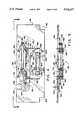
- FIG. 1is a side view of a cushioning dunnage machine according to the present invention, the machine being shown positioned in a horizontal manner and loaded with stock material with the external housing being removed for clarity of illustration;
- FIG. 2is an opposite side view of the cushioning dunnage machine of FIG. 1;
- FIG. 3is a top plan view of the cushioning dunnage machine of FIG. 1 without stock material loaded and as seen along line 3--3 in FIG. 1;
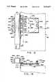
- FIG. 4is an isolated end view of the downstream side of the second or downstream frame end plate showing a cutting assembly attached thereto, as would be seen along line 4--4 in FIG. 1;
- FIG. 5is a plan view of the downstream frame end plate and the cutting assembly as seen along line 5--5 in FIG. 4 with the cover;
- FIG. 6is an enlarged view of a fixed blade adjustment portion of the cutting assembly and the downstream frame end plate as seen along line 6--6 in FIG. 4;
- FIG. 7is another bottom plan view of the fixed blade adjustment portion of the cutting assembly and the downstream frame end plate as seen along line 7--7 in FIG. 6;
- FIG. 8is an enlarged view of another embodiment of a fixed blade adjustment portion mounted on the end plate
- FIG. 9is another bottom plan view of the end plate and fixed blade adjustment of the cutting assembly of FIG. 8, as would be seen along line 9--9 in this Figure;
- FIG. 10is a vertical sectional view of the end plate and the cutting assembly of FIG. 8 as would be seen along line 10--10 in FIG. 9;
- FIG. 11is a side view of a packaging system according to the present invention employing two cushioning dunnage machines, the machines being mounted in a vertical manner on a machine mounting stand;
- FIG. 12is a front view of the packaging system of FIG. 11;
- FIG. 13is an enlarged view of some of the components used to mount the machines onto the machine mounting stand in the packaging system of FIG. 11;
- FIG. 14is a sectional view of the mounting components as seen along line 14--14 in FIG. 13;
- FIG. 15is a side view of another packaging system according to the present invention employing one cushioning dunnage machine positioned in a vertical manner;
- FIG. 16is a front view of the packaging system shown in FIG. 15;
- FIG. 17is a side view of yet another packaging system to the present invention, this system employing two cushioning dunnage machines positioned in a vertical manner and a remote stock roll supply assembly.
- FIGS. 1 through 3a cushioning dunnage conversion machine according to the present invention is indicated generally at 20.
- the machine 20is shown positioned in a horizontal manner and loaded with a roll 21 of sheet-like stock material 22.
- the stock material 22may consist of three superimposed webs or layers 24, 26, and 28 of biodegradable, recyclable and reusable thirty-pound Kraft paper rolled onto a hollow cylindrical tube 29.
- a thirty-inch roll of this paperwhich is approximately 450 feet long, will weigh about 35 pounds and will provide cushioning equal to approximately four fifteen cubic foot bags of plastic foam peanuts while at the same time requiring less than one-thirtieth the storage space.
- the machine 20converts this stock material 22 into a continuous unconnected strip having lateral pillow-like portions separated by a thin central band.
- This stripis connected or coined along the central band to form a coined strip which is cut into sections 32 of a desired length.
- the cut sections 32each include lateral pillow-like portions 33 separated by a thin central band and provide an excellent relatively low density pad-like product which may be used instead of conventional plastic protective packaging material.
- the machine 20includes a frame, indicated generally at 36, having an upstream or "feed” end 38 and a downstream or “discharge” end 40.
- the terms “upstream” and “downstream” in this contextare characteristic of the direction of flow of the stock material 22 through the machine 20.
- the frame 36is positioned in a substantially horizontal manner whereby an imaginary longitudinal line or axis 42 from the upstream end 38 to the downstream end 40 would be substantially horizontal.
- the frame 36is formed from a base plate 43 and two end plates 44 and 46.
- the frame base plate 43is generally rectangular and extends from the upstream end 38 to the downstream end 40 of the frame 36 in a generally horizontal plane.
- the first or upstream frame end plate 44may be more specifically described as a thin rectangular wall having a rectangular stock inlet opening 47 passing therethrough.
- the second or downstream frame end plate 46is generally rectangular and planar and includes a relatively small rectangular outlet opening 48. The outlet opening 48 may be seen more clearly by briefly referring to FIG. 4.
- the first frame end plate 44extends generally perpendicular in one direction from the upstream end of the frame base plate 43. In the illustrated embodiment of FIGS. 1 and 2, this direction is upward.
- the second end plate 46is preferably aluminum and extends in generally the same perpendicular direction from the downstream end of the frame base plate 43.
- the frame 36is basically "C" shape and one side of the frame base plate 43, which in this embodiment is the lower side, is a flat uninterrupted surface.
- the frame 36also includes a box-like extension 49 removably attached to a downstream portion of the base plate 43.
- the entire frame covercan be enclosed by a sheet metal housing or cover to protect the components mounted therein and to provide a safety factor for people using the machine.
- the frame 36is dimensioned so that the length of the machine 20 is approximately 56 inches; the width of the machine is approximately 34 inches; and the height of the machine is approximately 12 inches.
- the “length” of the machineis measured from its downstream end to its upstream end and thus this is defined by the frame base plate 43 and the extension 49.
- the "width” of the machineis the transverse dimension of the frame base plate 43; and the “height” of the machine is defined by the frame end plates 44 and 46.
- the machine 20further includes a stock supply assembly 50, a forming assembly 52, a gear assembly 54 powered by a gear motor 55 for pulling and connecting the paper dunnage, a cutting assembly 56 powered by a cutter motor 57, and a post cutting constraining assembly 58; all of which are mounted on the frame 36.
- the stock supply assembly 50is mounted to an upstream side of the first frame end plate 44.
- the forming assembly 52is located downstream of the stock supply assembly 50 and is mounted on an intermediate portion of the frame base plate 43.
- the gear assembly 54is located downstream of the forming assembly 52 and is mounted on an upstream side of the second frame end plate 46.
- the cutting assembly 56is mounted on the opposite downstream side of the frame end plate 46.
- the movable blade of the cutting assemblyis powered by a motor 57.
- the motors 55 and 57are mounted on the frame base plate 43 at about the same level as the forming assembly 52 and on opposite sides thereof.
- the post-cutting constraining assembly 58is located downstream of the cutting assembly 56 and is mounted on the box-like extension 49.
- the box-like extension 49shields the cutting assembly 56 from outside particles and interference during normal operation, however because it is detachable it may be removed if necessary to adjust and/or repair the cutting assembly 56.
- the machine 20may be positioned in a horizontal manner as shown in FIGS. 1 and 2, by placing the machine on a flat horizontal surface. While the floor of a packaging site may be appropriate, other surfaces such as tables and work benches may be more desirable.
- the machine 20may also be positioned in a vertical manner as shown in FIGS. 11, 12, 15, 16 and 17 whereby an imaginary longitudinal line from its upstream end to its downstream end would be substantially vertical. Additionally, two machines may be positioned symmetrically with respect to each other in close proximity as sometimes necessary to accommodate existing conveyor belts. (See FIGS. 11 and 17) Because of this flexibility, the machine 20 may accommodate packaging systems traditionally dominated by plastic protective material, such as those incorporating conveyor belts which are incompatible with conventional cushioning dunnage machines.
- the stock supply assembly 50supplies the stock material 22 to the forming assembly 52.
- the forming assembly 52causes inward rolling of the lateral edges of the sheet-like stock material 22 to form the lateral pillow-like portions 33 of the continuous strip.
- the gear assembly 54actually performs dual functions in the operation of the machine 20. One function is a "pulling" function in which the paper is drawn through the nip of the two cooperating and opposed gears of the gear assembly.
- the gear assembly 54is the mechanism which pulls the stock material 22 from the stock roll 21, through the stock supply assembly 50, and through the forming assembly 52.
- the second function performed by the gear assembly 54is a "coining" or "connecting" function.
- the gear assembly 54connects the strip by the two opposing gears coining its central band passing therethrough to form the coined strip.
- the cutting assembly 56cuts the strip into sections 32 of a desired length. These cut sections 32 then travel through the post-cutting restraining assembly 58.
- the stock supply assembly 50includes two laterally spaced brackets 62.
- the brackets 62are each generally shaped like a sideways “U” and have two legs 64 and 65 extending perpendicularly outward from a flat connecting base wall 66. (See FIGS. 1 and 2.)
- the base wall 66is suitably secured to the downstream side of the frame end plate 44, such that the leg 64 is generally aligned with the frame base plate 43.
- Both of the legs 64have open slots 70 in their distal end to cradle a supply rod 72.
- the supply rod 72is designed to extend relatively loosely through the hollow tube 29 of the stock roll 21. As the stock material 22 is pulled through the machine 20 by gear assembly 54, the tube 29 will freely rotate thereby dispensing the stock material 22.
- a pin(not shown) may be provided through one or both ends of the supply rod 72 to limit or prevent rotation of the supply rod 72 itself.
- the other legs 65 of the U-brackets 62extend from an intermediate portion of the frame end plate 44 and cooperate to mount a sheet separator, indicated generally at 74.
- the sheet separator 74includes three horizontally spaced relatively thin cylindrical separating bars 76, 77 and 78. The number of separating bars, namely three, corresponds to the number of paper layers or webs of the stock material 22.
- the sheet separator 74separates the layers 24, 26 and 28 of paper prior to their passing to the forming assembly 52. This "pre-separation" is believed to improve the resiliency of the produced dunnage product. Details of a separating mechanism similar to the separator 74 are set forth in U.S. Pat. No. 4,750,896; the entire disclosure of which has already been incorporated by reference.
- the bracket legs 65also cooperate to support a constant-entry bar 80 which is rotatably mounted on the distal ends of the legs.
- the bar 80provides a nonvarying point of entry for the stock material 22 into the separator 74 and forming assembly 52, regardless of the diameter of the stock roll 21.
- the point of entry of the stock material 22 into the separator 74remains constant. This consistency facilitates the uniform production of cut sections 32 of cushioning dunnage pad product. Details of a "roller member” or a "bar member” similar to the constant-entry bar 80 are set forth in U.S. Pat. No. 4,750,896.
- the forming assembly 52is the actual "conversion" component of the machine 20 and includes a three-dimensional bar-like shaping member 90, a converging chute 92, a transverse guide structure 93 and a "coining" or guide tray 94.
- the stock material 22travels between the shaping member 90 and the frame base plate 43 until it reaches the guide tray 94.
- the transverse guide structure 93 and the guide tray 94guide the stock material 22 longitudinally and transversely into the converging chute 92.
- the shaping member 90rolls the edges of the stock material 22 to form the lateral pillow-like portions 33 and the converging chute 92 coacts with the shaping member 90 to form the continuous strip of the desired geometry.
- the guide tray 94guides the strip into the gear assembly 54.
- the bar-like shaping member 90may be supported by a vertical strap (not shown) attached to the distal ends of the frame end plates 44 and 46 and depending hangers (not shown).
- the hangersare preferably adjustable so that the position of the shaping member 90 relative to other components of the forming assembly 52, such as the converging chute 92, may be selectively varied.
- Further structural details of a shaping member 90 or "forming frame"are set forth in U.S. Pat. No. 4,750,896; the entire disclosure of which has already been incorporated by reference.
- the guide tray 94is directly mounted on the frame base plate 43; while the transverse guide structure 93 and the converging chute 92 are mounted on the guide tray 94.
- the guide tray 94is trapezoidal in shape, as viewed in plan, having a broad upstream side 105 and a parallel narrow downstream side 106.
- the broad side 105is positioned downstream of at least a portion of the shaping member 90.
- the narrow side 106is positioned adjacent the outlet opening 48 in the frame end plate 46 and includes a rectangular slot 107 to accommodate the gear assembly 54.
- the guide trayis not positioned parallel with the frame base plate 43, but rather slopes away (upwardly in FIGS. 1 and 2) from the frame base plate 43 to the gear assembly 54.
- the converging chute 92is mounted on the guide tray 94 upstream of at least a portion of the shaping member 90 and downstream slightly from the broad side 105 of the guide tray 94.
- the transverse guide structure 93is mounted on the guide tray 94 just upstream of the entrance mouth of the converging chute 92.
- the transverse guide structure 93includes rollers 108 rotatably mounted on a thin U-bracket 109. The distal ends of the U-bracket 109 are secured to the guide tray 94. Except for this mounting arrangement, the transverse guide structure 93 is similar to the "rollers and wire frame" disclosed in U.S. Pat. No. 4,750,896.
- the stock material 22travels over the guide tray 94, under the upstream end of the shaping member 90, between the rollers 108 of the transverse guide structure 93, and into the converging chute 92.
- the basic cross-sectional geometry and functioning of the converging chute 92is similar to that of the converging member described in U.S. Pat. No. 4,750,896.
- one improvement over the conventional chutesis that a top portion of converging chute 92 is formed by a cover 110 pivotally connected by hinges 111 to the remaining or bottom portion of the chute. This arrangement is especially helpful during the initial "threading" of the machine 20.
- the pivot cover 110allows the converging chute 92 to be opened to aid in manually threading the stock material through the chute and closed when the machine is ready for automatic operation.
- the stock material 22will emerge from the chute as the continuous unconnected strip.
- the emerging stripis guided to the gear assembly 54 by the narrow downstream end 106 of the guide tray 94, which extends from the outlet opening of the chute to the outlet opening 48 in the frame end plate 46.
- the gear assembly 54includes loosely meshed horizontally arranged drive gear 124 and idler gear 126 between which the stock material 22 travels.
- the gears 124 and 126are turned the appropriate direction, which in FIG. 1 would be counterclockwise for gear 124 and clockwise for gear 126, the central band of the strip is grabbed by the gear teeth and pulled downstream through the nip of gears 124 and 126. This same "grabbing" motion caused by the meshing teeth on the opposed gears 124 and 126 simultaneously compresses or "coins" the layers of the central band together thereby connecting the same and forming the coined strip.
- the drive gear 124is positioned between the frame base plate 43 and the guide tray 94 and projects through the rectangular slot 107 in the guide tray 94.
- the gear 124is fixedly mounted to a shaft 130 which is rotatively mounted to the upstream side of the frame end plate 46 by bearing structures 131.
- a sprocket 132 at one end of the shaftaccommodates a chain 133 which connects the shaft 130 to a speed reducer 136.
- the speed reducer 136acts as an interface between the gear assembly 54 and the gear motor 55 for controlling the rate of "pulling" of the stock material 22 through the machine 20.
- the gear motor 55 and the speed reducer 136are mounted on the frame base plate 43 at approximately the same level as the forming assembly 52.
- the idler gear 126is positioned on the opposite side of the guide tray 94 and is rotatively mounted on a shaft 140.
- Shaft brackets 142 attached to an upstream side of the frame end plate 46nonrotatively support the ends of the shaft 140 in spring-loaded slots 144.
- the slots 144allow the shaft 140, and therefore the idler gear 126, to "float" relative to the drive gear 124 thereby creating an automatic adjustment system for the gear assembly 54.
- a similar gear assembly or "connecting means"is described in U.S. Pat. No. 4,750,896.
- the gear assembly 54transforms the unconnected strip into the coined strip and this strip travels through the outlet opening 48 in the frame end plate 46.
- the coined stripis then cut by the cutting assembly 56 into cut sections 32 of the desired length. Details of the cutting assembly 56 and the frame end plate 46 may be seen in FIGS. 4 and 5 where these components are shown isolated from the rest of the machine 20. As is best seen in FIG. 4, which shows the downstream side of the frame end plate 46, the roughly rectangular end plate 46 has two square notches 150 at the corners on its proximal side and an offset open slot 152 on its distal side.
- proximal and distalin this context refer to the location of the side relative to the frame base plate 43.
- the square notches 150coordinate with the frame base plate 43 for attachment purposes and the offset open slot 152 accommodates the drive of cutting assembly 56.
- the rectangular outlet opening 48it is defined by a proximal side 154, a distal side 156 and two smaller lateral sides 158.
- the cutting assembly 56includes a stationary blade 160 and a shear or sliding blade 162, both blades being strategically positioned relative to the outlet opening 48.
- the blades 160 and 162are the actual "cutting" elements of the cutting assembly 56 and coact in a guillotine fashion to cut the coined strip into the cut sections 32.
- the stationary blade 160is fixedly (but adjustably) mounted on the frame end plate 46 by a stationary blade clamp 164 and stationary support bar 165.
- the shear bladeis slidably mounted on the end plate within cutter guide bars 166.
- the stationary blade clamp 164is positioned so that the blade 160 is aligned with the proximal side 154 of the outlet opening 48.
- the cutter guide bars 166are positioned beyond and parallel to the lateral sides 158 of the outlet opening 48.
- the bars 166also extend beyond the proximal and distal sides 154 and 156 of the outlet opening 48. This positioning and sizing of the guide bars 166 allows the sliding blade 162 to travel from an open position completely clearing the outlet opening 48 as shown in FIG. 4 to a closed position beyond the stationary blade 160.
- the sliding blade 162is connected to a cutter linkage, indicated generally at 170, via a stabilizer bar 172.
- the cutter linkage 170includes two laterally spaced arms 174 pivotally connected at 176 to the downstream side of second frame end plate 46; two laterally spaced arms 180 pivotally connected to the stabilizer bar at 182; and an arm 184.
- the arm 184is pivotally connected at 186 to one set of arms 174 and 180, and is pivotally connected at 190 to the other set of arms 174 and 180.
- the arm 184is also pivotally connected to a drive link 192 at 190.
- the drive link 192is connected at 193 to a tangential portion of a motion disk 194.
- a shaft 196is connected at one end to the motion disk 194 and extends from the downstream side of the frame end plate 46, through the open offset slot 152 to the upstream side of the plate 46.
- the opposite end of the shaft 196is connected to a clutch assembly 210 which is mounted on the upstream side of the frame end plate 46.
- the clutch assemblyis connected to the output shaft of cutter motor 57 by an endless drive chain 211.
- the clutch assembly 210serves as an interface between the shaft 196 (and therefore the motion disk 194) and the cutter motor 57 to change and/or regulate the rotation of motion disk 194.
- the position of the drive link 192will be varied to drive the linkage assembly 170 to move the sliding blade 162 to and fro within the guide bars 166 at a desired interval.
- One rotation of the motion disk 194will move the sliding blade through one cycle of making a cutting stroke through the coined strip and a return stroke to the open position shown in FIG. 9.
- the coined stripwill be cut by a "shearing" action between the stationary blade 160 and the sliding blade 162.
- the sliding blade 162is offset a slight distance downstream from the stationary blade 160 and the magnitude of this offsetting distance is critical to the operation of the cutting assembly 56. If the distance is too great, a "gap" will be created between the blades and the coined strip will not be cut properly. If the distance is too small, the blades may be damaged during the cutting process.
- the dimensional range between a "too great” and “too small” settingis about 0.005 inches.
- the stationary blade 160may be mounted to the frame end plate 46 in a manner making manual adjustments possible.
- One such manual manneris shown in FIGS. 4 and 5 and in further detail in FIGS. 6 and 7.
- the support bar 165is sandwiched between the stationary blade 160 and the blade clamp 164 and is unadjustably or fixedly secured to the frame end plate 46 by fasteners 230. (FIGS. 4 and 6.)
- the stationary blade 160is attached to the blade clamp 164 by fasteners 231 which travel through openings 232 in the support bar 165.
- the fasteners 231 and the openings 232are dimensioned to create a slight clearance between a fastener 231 and an opening 232 whereby the openings may be viewed as "enlarged.”
- the magnitude of this clearancewould be in the order of 0.005 inch and accordingly difficult to reflect in the illustrations.
- the blade clamp 164includes a moving clamp part 240 adjustably mounted to a pair of mounting clamp parts 242.
- the block-shape mounting clamp parts 242are fixedly secured to the frame end plate 46 and each part has a threaded opening 243.
- the stationary blade 160is attached to the moving clamp part 240 and thus adjustment of the moving clamp part 240 relative to the mounting clamp parts 242 results in adjustment of the blade 160 relative to the frame end plate 46 to the extent permitted by the clearance between fasteners 231 and openings 232.
- the moving clamp part 240is a bar-shape piece having an open slot 244 forming two thongs 245 at each end (see FIGS. 6 and 7). Lock screws 246 may be inserted through outer openings in the clamp part 240 to brace the thongs on each end together. Adjustment screws 250 extending through inset openings 252 secure the moving clamp part 240 to the mounting clamp parts 242. The inset openings 252 are arranged so that adjustment screws 250 may mate with the threaded openings 243 in the mounting clamp parts 242.
- the adjustment screws 250 and the openings 252are dimensioned to permit a certain amount of play between these components so that the moving clamp part 240 may be adjusted relative to the mounting clamp parts 242.
- An adjustment of the moving clamp part 240results in corresponding movement of the stationary blade 160 whereby the cutting assembly 56 may be manually adjusted. Because the fasteners 231 connecting the stationary blade 160 to the moving clamp part 240 extend through the enlarged openings 232 in the blade support bar 165, the movement of the clamp part 240 and the stationary blade 160 is limited by the size of the openings 232.
- the slight clearance between the fasteners 231 and the openings 232should therefore be dimensioned to allow the necessary adjustments in the range of 0.005 inches.
- the lock screws 246are rotated to draw the thongs 245 together to decrease the width of the gap therebetween. By decreasing this gap, the thongs bind the adjustment screws 250 precluding rotation thereof, thereby to lock the fixed blade 160 in the selected position.
- FIGS. 8, 9 and 10Another manner of mounting the stationary blade 160 to insure proper blade positioning during the shearing action is shown in FIGS. 8, 9 and 10.
- the stationary blade 160is spring-loaded toward the sliding blade 162 so that the cutting assembly 56 is "self-adjusting.”
- the sliding blade 162will urge the stationary blade 160 inwardly (upstream) to provide the necessary clearance between the blades.
- the stationary blade 160is effectively adjusted on each cutting stroke thereby minimizing blade damage caused by inadequate clearance and improper cutting caused by overly separated blades.
- This "self-adjustment" of the cutting assembly 56is accomplished by employing a mounting angle bracket 260 and a resilient angle bracket 262, each having a pair of perpendicular walls.
- the mounting angle bracket 260has one wall 264 positioned parallel and adjacent to the frame end plate 46 and another perpendicular wall 266 extending outwardly (downstream).
- Support blocks 270are positioned at each end of the mounting angle bracket 260 and fasteners 272, which extend through the blocks 270, wall 264, and the end plate 46, fixedly secure the blocks 270 and the mounting angle bracket 260 to the second frame end plate.
- the outwardly extending wall 266 of mounting angle bracket 260is also secured to each of the support blocks 270 by fasteners 274.
- the resilient angle bracket 262has one wall 280 positioned adjacent the mounting bracket wall 266 and another perpendicular wall 282 positioned opposite the bracket wall 264. (See FIG. 10)
- the resilient angle bracket 262is secured to both the mounting angle bracket 260 and the stationary blade 160 by two laterally spaced fasteners 283, with the brackets being arranged so that the blade 160 is aligned with the proximal side 154 of the outlet opening 48.
- the fasteners 283extend through aligned openings in the stationary blade 160, the mounting bracket wall 266, and the resilient bracket wall 280.
- the aligned openings 284 in the mounting bracket wall 266are oversized or elongated when compared to the fasteners 283 creating a clearance between the fasteners 283 and the openings 284.
- Bushingsmay be used lock the stationary blade 160 to the resilient angle bracket 262.
- the resilient angle bracket 262is urged away or downstream from the mounting angle bracket 260 and the frame end plate 46 by springs 285.
- the springs 285are supported on screws 286 which are attached at one end to the mounting bracket wall 264.
- the opposite ends of the spring support screws 285extend through openings in the resilient bracket wall 280 and are capped by nuts 288. These openings in the wall 280 are dimensioned to permit slidable movement between the resilient angle bracket 262 and the screws 286 as the springs are compressed or expanded during operation of the cutting assembly 56.
- the stationary blade 160is attached to the resilient angle bracket 262 by fasteners 283 whereby the springs 285 also urge the stationary blade 160 in the same downstream direction towards the sliding blade 162.
- the movement of both the resilient angle bracket 262 and the stationary blade 160 in either directionis limited by the ends of the oversized openings 284 in the mounting bracket 260 through which the fasteners 283 extend. Accordingly, these openings should be dimensioned to provide the necessary play between the blades 160 and 162.
- both manual and “self” adjusting cutting assembliesmay be used to properly position the blades 160 and 162.
- the coined stripis divided into cut sections 32 of the desired length. These cut sections 32 then travel downstream to the post-cutting constraining assembly 58 which helps the cut sections to retain their desired geometry and thereby improve their cushioning capacity.
- the post-cutting constraining assembly 58is located downstream of the cutting assembly 56 and is mounted on the box-like extension 49 of the frame 36.
- the post-cutting constraining assembly 58is basically funnel-shaped and includes an upstream converging portion 300 which tapers into a downstream rectangular tunnel portion 302.
- the converging portion 300is located between the downstream frame end plate 46 and the extension 49, while the tunnel portion 302 extends through and beyond the frame extension 49.
- the post-cutting constraining assembly 58is positioned so that its inlet 304 is aligned with the outlet opening 48 of the end plate 46.
- the downstream outlet 306 of the post-cutting constraining assembly 58is also preferably aligned with the outlet opening 48 and also the inlet 304.
- a cut section 32will be urged or pushed downstream into the inlet 304 of assembly 58 by the approaching coined strip.
- the converging portion 300smoothly urges the section 32 into the tunnel portion 302. As the cut section 32 passes through the tunnel portion 302, it is generally constrained circumferentially and longitudinally guided which are believed to improve its cushioning quality.
- a cut section 32 emerging from the post-cutting constraining assembly 58may be directed to a desired packing location, the conversion of stock material 22 to cut sections 32 of relatively low density pad-like cushioning dunnage product now being complete.
- cut sections 32are produced by a machine 20 which is compatible with both horizontal and vertical positioning.
- Other features, such as the pivot cover 110 on the converging chute 92 and the post-cutting constraining assembly 58improve the operating efficiency of the machine and/or the cushioning quality of the product.
- FIGS. 11-17various packaging systems employing one or more machines 20 are shown.
- the frame 36is positioned in a substantially vertical manner whereby the imaginary longitudinal line 42 drawn from the upstream end 38 to the downstream end 40 would be substantially vertical.
- the stock supply assembly 50includes "L" shaped brackets 307, instead of the "U" shaped brackets 62 employed in the machine illustrated in FIGS. 1 and 2.
- the stock roll 21will be mounted at a remote location. For this reason, the one leg 64 of the "U" shaped bracket 62 is unnecessary.
- "U" shaped bracketscould be used in a vertically mounted machine and the stock roll 21 could be mounted in the manner shown in FIGS. 1-3. Additionally, even if the stock roll 21 was mounted remote from the machine 20, "U" shaped brackets could still be used by mounting a second constant-entry bar 80 on the distal ends of the unoccupied legs 64.
- the stock supply assembly 50includes two "L” shaped brackets 307.
- the "L” shaped brackets 307each have one leg 308 extending perpendicularly outwardly from one end of a flat wall 309.
- the flat walls 309are suitably secured to the upstream side of the frame end plate 44 such that their free ends are aligned with frame base plate 43.
- the legs 308extend from an intermediate portion of the frame end plate 44 and cooperate to mount the sheet separator 74 and the constant-entry bar 80.
- the machines 20 illustrated in these systemsinclude a cover 310 removably placed on the machine to improve its exterior appearance and/or to protect its interior components.
- the cover 310includes three sides: one longitudinal side 312 and two transverse sides 314.
- the longitudinal side 312is positioned parallel to the frame base plate 43 and extends between the distal sides of the frame end plates 44 and 46.
- the machine 20 employed in the packaging systems shown in FIGS. 11-17may be mechanically and structurally identical to the machine 20 illustrated in FIGS. 1-10 and described above.
- the packaging system 320employs two cushioning dunnage machines 20 orientated so that their upstream ends are positioned above their downstream ends.
- the system 320also includes a machine mounting stand 322 for mounting the machines 20 in the desired orientation, a packaging surface in the form of two parallel closely spaced independently supported conveyer belts 324, and a stock dispenser comprising two stock supply carts, indicated generally at 326.
- the components of the packaging system 320are coordinated so that stock rolls 21 may be mounted on the stock supply carts 326, stock material 22 may be fed into the upstream end of the machine 20, and the converted cut sections 32 of cushioning material may be dropped into shipping cases (not shown) traveling on the conveyer belts 324 in the direction symbolized by arrow 328.
- the machine mounting stand 322includes a floor support, indicated generally at 330, and two vertical posts 332 extending upwardly therefrom.
- the floor support 330is generally "H" shaped when viewed from the front and includes two side members 334 extending outwardly from both sides of an elevated lower cross bar 336.
- Leveling feet 340 on the distal ends of the side members 334allow for adjustment or leveling of the machine mounting stand 322 on the floor of the packaging site.
- the lower cross bar 336is positioned between the conveyor belts 324 in a direction parallel to the flow direction 328 whereby half of each of the side members 334 is positioned beneath one of the conveyor belts 324.
- the side members 334 and the lower cross bar 336together define three sides of a rectangular space under each conveyor belt 324 into which the stock supply carts 326 may neatly fit.
- the vertical posts 332are secured to the side members 334 by two triangular braces 342 and extend upwardly between the conveyor belts 324.
- the lower cross bar 336is secured to the vertical posts 332 by T-braces 346 located just above the triangular braces 342.
- the vertical posts 332are further braced together by a top cross bar 350 attached by L-braces 352 to the top ends of the vertical posts.
- the vertical posts 332, the lower cross bar 336 and the top cross bar 350together define a rectangular open space 353 in a substantially vertical plane between the machines 20.
- the machines 20are mounted on the vertical posts 332 by sliders, indicated generally at 360, whereby the machines may be vertically adjusted on the machine mounting stand 322.
- the packaging system 320may be modified to accommodate conveyor belts of various heights, different shaped shipping cases and/or diverse density cushioning products.
- a cable(not shown), which is connected to a winch 361 and pulleys 362 and 363, controls the position of the sliders 360 on the vertical posts 332.
- the winch 361is mounted on one of the vertical posts 332 at floor level for convenient access while the pulleys 362 and 363 are positioned at the top ends of the vertical posts 332.
- the vertical positioning of the machines 20may be adjusted by turning the winch 361 and the pulleys 362 and 363 will assure equal vertical adjustment of the two sliders 360.
- the sliders 360 and the actual attachment of the sliders 360 to the machines 20 and the vertical posts 332are shown in detail in FIGS. 13 and 14.
- this attachment arrangementallows horizontal or "tilt" adjustments of the machines 20 relative to the machine mounting stand 322 whereby two-dimensional fine-tuning of the packaging system 320 is possible.
- Each of the sliders 360has a central square channel 364 dimensioned to encase one of the vertical posts 332.
- Two side angle brackets, indicated generally at 365, having perpendicular wallsare attached to opposite sides of the square channel 364. More particularly, one wall 366 of each angle bracket 365 is secured to one side of the channel 364, while each of the other walls 367 extends outwardly therefrom in opposite directions.
- the outwardly extending wall 367 on one bracketis attached to a swivel plate 370 by fasteners 371.
- the fasteners 371extend through four openings 372 in the wall 367 and aligning openings 373 located along one edge of the swivel plate 370.
- the swivel plate 370also includes a second set of openings 373 which are located along a central band of the swivel plate 370 and the side angle brackets 365 include a fifth larger central opening 374 between the openings 372.
- the second set of openings 373 and the central opening 374permit this mounting arrangement to accommodate other packaging systems as will be explained in more detail below.
- the swivel plate 370is selectively secured to a stop plate 375 which is almost identical in shape to the swivel plate 370 and thus it is hidden in FIG. 13.
- the stop plate 375is attached at one edge to a machine mount angle bracket 376 by fasteners 377, the bracket 376 being fixedly secured to a corner of the machine 20.
- the swivel plate 370has a semi-circular array of openings 378 through which a spring plunger 379 may be inserted and received in an opening 380 in the stop plate 375.
- the stop plate 375may be additionally rotatively attached to the swivel plate 370 by a pivot fastener 381.
- the spring plunger 379is inserted through the central opening 378, thus positioning the machine in an almost exact vertical manner.
- the spring plunger 379may be removed to allow the stop plate and machine 20 to be pivoted about pivot fastener 381.
- the spring plungermay then be selectively inserted through any of the offset openings 378 aligned therewith whereby the stop plate 375 and the attached machine would be tilted. This ability to tilt the machines 20 allows a "fine tuning" of packaging system 320.
- FIGS. 13 and 14While in FIGS. 13 and 14, only one swivel plate 370 and machine 20 are shown attached to the slider 360, the second machine of the packaging system 320 would be mounted symmetrically to the other side angle bracket 365 by its own swivel plate 370 and other associated components.
- the vertical adjustment of the machines 20would always be the same because they share the sliders 360.
- the tilt of one of the machines 20could be set independently of the other machine by adjusting the corresponding spring plunger 379 position in the swivel plate 370.
- the magnitude of tilting adjustment which would be possible in the packaging system 320would be limited by the thickness of the rectangular space 353 between the machines 20.
- the machines 20receive stock material 22 from the stock dispenser, or the stock supply carts 326.
- the stock supply carts 326are located beneath the conveyor belts 324 in the rectangular spaces defined by the side members 334 and the lower cross bar 336 of the machine mounting stand 322.
- Each of the stock supply carts 326includes a rectangular bottom tray 382 having rollers 384 pivotally attached to each of its four corners. The rollers 384 make the carts 326 mobile allowing them to be conveniently rolled in and out from the under the conveyor belt 324 for loading/unloading purposes.
- Each stock supply cart 326further includes two "H" shaped side members 386 each having two vertical legs 387 extending from two adjacent corners of the bottom tray 382 and a connecting arm 388.
- the connecting arms 388include a central recess in which a supply rod 72 extending through the hollow tube 29 of the stock roll 21 may be cradled.
- the cart 326To guide the stock material in its upward path to the stock supply assembly 50, the cart 326 includes a deflector 390 and a guiding rod 392.
- the deflector 390is attached to and extends between an intermediate portion of two adjacent vertical legs 387 which are not part of the same "H" shaped side member 386.
- the deflector 390is shaped basically like a prism and has an upwardly sloping side 394 positioned adjacent to the stock roll 21.
- the guiding rod 392is rotatively attached to and extends between an upper portion of the same vertical legs 387 to which the deflector 390 is attached. As is best seen in FIG.
- the stock material 22travels from the open space 353 to the stock supply assembly 50, through the forming assembly 52, the gear assembly 54 and the cutting assembly 56 to be converted into cut sections 32.
- the cut sections 32travel through the post-cutting constraining assembly 58 which in the illustrated embodiment is surrounded by a pad chute 395.
- the pad chute 395is attached to the downstream end of the frame 36 and acts an external guide assembly for directing the cut sections 32 to the desired packing location.
- FIGS. 15 and 16Another packaging system 400 according to the present invention is shown in FIGS. 15 and 16, this system including only one machine 20 orientated with its downstream end positioned above its upstream end. Such an arrangement may be desirable due to height limitations in the packaging facility and/or other considerations.
- the packaging system 400also includes a machine mounting stand 402 for mounting the machine 20 in this orientation, a packaging surface in the form of a single conveyor belt 404, and a stock dispenser comprising a stock supply cart 406.
- the stock supply cart 406is similar to the stock supply carts 326 described above in reference to FIGS. 11 and 12 except that stock supply cart 406 has neither a deflector 390 nor a guiding rod 392.
- the conveyor belt 404is likewise similar to the conveyor belts 324 of system 320 except that conveyor belt 404 is supported, at least in part, by the machine mounting stand 402.
- the componentsare arranged so that the stock material 22 passes from the roll 21 slightly downwardly to the constant-entry bar 80 and then continues upwardly through the sheet separator 74 and the rest of the machine.
- the machine mounting stand 402includes a floor support 410 and two vertical posts 412 extending therefrom.
- the floor support 410is generally "U" shaped and has two side members 416 extending perpendicularly from a connecting cross bar 418.
- the cross bar 418is positioned parallel to the flow direction of the conveyor belt 404, however it is offset from the conveyor belt 404 in one direction, this direction being to the left in FIG. 15.
- Leveling feet 420may be provided on the two ends of each of the side members 416 for adjustment purposes.
- the side members 416 and the cross bar 418together define three sides of a rectangular space under the conveyor belt 404 into which the stock supply cart 406 neatly fits.
- the vertical posts 412are secured to the side members 416 by triangular braces 422 secured to the proximal ends of the side members 416. As is best seen in FIG. 16, the mounting stand 402 does not include a top cross bar. Additionally, the space between the vertical posts 412 is occupied by the machine 20, while the area between the posts 412 and below the machine 20 is left relatively open for the stock material 22 to pass from the stock roll 21 to the stock supply assembly 50.
- the machine 20is again selectively slidably mounted on the vertical posts 412 by sliders 424 which may be identical to the sliders 360 used in the packaging system 320.
- the sliders 424are attached to the transverse sides 314 of the machine cover 310. With this attachment arrangement, it may be desirable to permanently and securely attach the transverse sides 314 of the cover 310 to the frame 36 of the machine while making the longitudinal side 312 of the cover 310 selectively removable as by hinge 425.
- the machine 20is mounted to the sliders 424 by the same mounting components shown in FIGS. 13 and 14 and employed in the packaging system 320.
- the left-hand side angle bracket 365would be secured to the swivel plate 370 by fasteners 37 extending through the second central set of openings 373.
- the right-hand side angle bracket 365would be secured to the swivel plate 370 and the stop plate 375 by the spring plunger 379.
- the spring plunger 379would pass though the larger central hole 374 in the wall 367 of the right-hand bracket 365 and through one of the openings 378 in the circular array.
- the machine mounting stand 402further includes a conveyor support 440 on which the conveyor belt 404 is at least partially supported.
- the conveyor support 440includes two vertical bars 442 attached to the distal ends of the side members 416 by L-braces 444; two horizontal bars 446 connected to an intermediate portion of the vertical posts 412 by T-braces 450; and a third horizontal bar 452 connected to the first and second horizontal bars 446 by the T-braces 455.
- the conveyor belt 404rests on the horizonal bars 446 and 452 and is thereby positioned beneath the pad chute 460. Cut sections 32 will be dropped from the pad chute 460 into shipping cases (not shown) traveling on the conveyor belt 404.
- FIG. 17yet another packaging system 500 according to the present invention is shown, this system employing two machines 20.
- the machines 20are again positioned in a vertical manner and in this system the upstream or "feed” end of the machines are located above their downstream or “discharge” ends.
- Several differences between the packaging system 500 and systems 320 and 400may be initially noted.
- the two machines 20are fixedly, rather than slidably, mounted to a machine mounting stand 502.
- This stand 502may simply be a single vertical wall with one of the machines 20 mounted on each side.
- the system 500has nonmoving packing stations or tables 504. Further, the system 500 does not have stock supply carts but instead includes a permanent nonmovable stock supply structure 506.
- the stock supply structure 506includes two parallel vertical beams 510 of about the same height as the mounting stand 502 and positioned remote therefrom.
- An upper stock dispenser 512 and a lower stock dispenser 514are secured to the lower ends of the vertical beams 510.
- Each dispenserholds two rolls 21 of stock material 22 and the positioning of the dispensers 512 and 514 at this location permits safe and convenient reloading of the stock material 22 at floor level.
- the machines 20are loaded with stock material 22 from the stock rolls 21 held in the upper stock dispenser 512.
- stock material 22 from the stock rolls 21 held in the lower stock dispenser 514could be just as easily loaded into the machine 20 if necessary or desired.
- the dispensers 512 and 514are essentially identical and each is comprised of two side members 516, one side member being perpendicularly secured to each of the vertical beams 510.
- the distal end of each of the side members 516includes a recess 518 for cradling the supply rod 72, whereby each dispenser holds two stock rolls 21.
- the dispensersfurther include two limit switches 520, one for each of the rolls.
- a tape container 522 for a roll of tape 514may be conveniently secured between the upper dispenser 512 and the lower dispenser 514.
- the stock supply structure 506further includes two horizontal beams 526, each beam 526 connecting the top end of one of the vertical beams 510 to the top end of the machine mounting stand 502.
- Small upper guide rods 527extend from one beam 526 to the other beam thereby forming an upper guide track for stock material 22 from the stock roll 21 positioned to the right in FIG. 17.
- small lower guide rods 528extend from one beam to the other beam thereby forming a lower guide track for stock material 22 from the stock roll 21 positioned to the left in FIG. 17.
- the lower guide rods 528are slightly horizontally offset from the upper guide rods 527.
- the stock material 22will travel from the upper stock dispenser 512 upwardly to the corner formed by the beams 510 and 526. At this corner, the stock material must essentially make at 90° turn to continue its path to the machine 20.
- two guide rods 530 and 532are rotatively mounted at this corner.
- the upper guide rod 530is positioned slightly outwardly from the vertical beams 510 to align the stock material from the right hand stock roll with the upper guide track.
- the lower guide rod 532is positioned to align the stock material from the left hand roll with the lower guide track. In this manner, the stock material 22 smoothly passes into the guide tracks.
- the stock materialmust again make an essentially 90° turn to enter a machine 20.
- This transitionis accomplished by the constant-entry bars 80 of the stock supply assemblies 50.
- the left hand machine 20which receives stock material 22 from the right hand stock roll 21, is positioned so that its constant-entry bar 80 is aligned with the upper guide track.
- the right hand machinewhich receives stock from the left hand stock roll, is mounted slightly below the left hand machine so that its constant-entry bar 80 is aligned with the lower guide track.
- Deflectors 540may be strategically mounted on the machine mounting stand 502 to urge the cut sections 32 towards the proper part of the mounting stand 502.
- the deflectors 540are shaped generally like a prism having an outwardly sloping wall 542, the slope and the length of the wall 542 being determinative of where the cut sections 32 will drop on the packing stations 504.
- packaging systems according to the present inventionmay be incorporated into and/or initiated at a multitude of packaging sites. Additionally, these and other packaging systems employing one or more cushioning dunnage conversion machines 20 may be appropriately modified to suit many applications. This wide range of compatibility makes biodegradable, recyclable and renewable paper protective packaging material a very attractive alterative to plastic bubble wrap and/or plastic foam peanuts. Thus industries may now more easily make the environmentally responsible choice of paper rather than plastic protective packaging material.
Landscapes
- Life Sciences & Earth Sciences (AREA)
- Forests & Forestry (AREA)
- Engineering & Computer Science (AREA)
- Mechanical Engineering (AREA)
- Making Paper Articles (AREA)
Abstract
Description
Claims (30)
Priority Applications (40)
| Application Number | Priority Date | Filing Date | Title |
|---|---|---|---|
| US07/592,572US5322477A (en) | 1990-10-05 | 1990-10-05 | Downsized cushioning dunnage conversion machine and packaging systems employing the same |
| US07/712,203US5123889A (en) | 1990-10-05 | 1991-06-07 | Downsized cushioning dunnage conversion machine and cutting assemblies for use on such a machine |
| AT95114045TATE183962T1 (en) | 1990-10-05 | 1991-10-01 | MACHINE FOR PRODUCING UPHOLSTERY ELEMENTS FROM WEB-SHAPED MATERIAL |
| DK97119828TDK0827826T3 (en) | 1990-10-05 | 1991-10-01 | Packing system including a liner material conversion machine and method of using such a system |
| AT97119828TATE241461T1 (en) | 1990-10-05 | 1991-10-01 | PACKAGING SYSTEM WITH A MACHINE FOR PRODUCING UPHOLSTERY ELEMENTS AND ITS APPLICATION |
| DE9116971UDE9116971U1 (en) | 1990-10-05 | 1991-10-01 | Small-sized conversion machine for cushioning backing material and packaging systems using the same |
| ES97119828TES2196239T3 (en) | 1990-10-05 | 1991-10-01 | PACKING SYSTEM THAT INCLUDES A TRANSFORMING MACHINE FOR PAD AND PROCEDURE USING THIS SYSTEM. |
| DE0688664TDE688664T1 (en) | 1990-10-05 | 1991-10-01 | Upholstery conversion machine and packaging system for their application |
| AT91919335TATE139476T1 (en) | 1990-10-05 | 1991-10-01 | DEVICE FOR PRODUCING SHOCK-ABSORBING DAMPING ELEMENTS FROM SHEET MATERIAL AND METHOD THEREFOR |
| AT95105394TATE168930T1 (en) | 1990-10-05 | 1991-10-01 | MACHINE FOR MAKING UPHOLSTERY SECTIONS FROM WEB-SHAPED MATERIAL |
| EP19970119828EP0827826B9 (en) | 1990-10-05 | 1991-10-01 | Packaging system comprising a cushioning conversion machine and method of using such a system |
| ES95114045TES2136778T3 (en) | 1990-10-05 | 1991-10-01 | MACHINE FOR THE CONVERSION OF MATERIAL IN ELEMENTS OF STOCK AND CUSHIONING. |
| DE1991633271DE69133271T2 (en) | 1990-10-05 | 1991-10-01 | Packaging system with a machine for producing upholstery elements and its application |
| EP19950114045EP0688664B1 (en) | 1990-10-05 | 1991-10-01 | Cushioning dunnage conversion machine for converting a sheet-like stock material into a dunnage product |
| DE9117231UDE9117231U1 (en) | 1990-10-05 | 1991-10-01 | Small-sized conversion machine for cushioning backing material and packaging systems using the same |
| DE0677379TDE677379T1 (en) | 1990-10-05 | 1991-10-01 | Upholstery conversion machine and packaging system for their application. |
| DE69131583TDE69131583T2 (en) | 1990-10-05 | 1991-10-01 | Machine for producing upholstery elements from sheet material |
| DE9116966UDE9116966U1 (en) | 1990-10-05 | 1991-10-01 | Small-sized conversion machine for cushioning backing material and packaging systems using the same |
| DE69120427TDE69120427T2 (en) | 1990-10-05 | 1991-10-01 | Device for producing shock-absorbing damping elements from sheet material and method therefor |
| PCT/US1991/007049WO1992005948A1 (en) | 1990-10-05 | 1991-10-01 | Downsized cushioning dunnage conversion machine and packaging systems employing the same |
| HK98107104AHK1007988A1 (en) | 1990-10-05 | 1991-10-01 | Cushioning dunnage conversion machine and method of producing cut sections of cushioning dunnage product |
| EP19950105394EP0677379B1 (en) | 1990-10-05 | 1991-10-01 | Apparatus for converting sheet-like stock material into cut sections of dunnage |
| EP19910919335EP0554338B1 (en) | 1990-10-05 | 1991-10-01 | Cushioning dunnage conversion machine and method of producing cut sections of cushioning dunnage product |
| JP51678891AJP3384801B2 (en) | 1990-10-05 | 1991-10-01 | Small buffer dunnage converter and package system using it |
| DK95114045TDK0688664T3 (en) | 1990-10-05 | 1991-10-01 | Attenuating casing conversion machine for converting a sheet or web-shaped module into a casing product |
| CA002093124ACA2093124C (en) | 1990-10-05 | 1991-10-01 | Downsized cushioning dunnage conversion machine and packaging systems employing the same |
| AU86622/91AAU664357B2 (en) | 1990-10-05 | 1991-10-01 | Downsized cushioning dunnage conversion machine and packaging systems employing the same |
| DE69129911TDE69129911T2 (en) | 1990-10-05 | 1991-10-01 | Machine for producing upholstery sections from sheet material |
| PT99162APT99162B (en) | 1990-10-05 | 1991-10-04 | MACHINE FOR THE TRANSFORMATION OF DAMPING CALCULATIONS USED ON THE ESSENCE IN PEDACOS OF SMALL CUTTED DIMENSIONS AND PACKING SYSTEMS THAT USE IT |
| IE350091AIE68345B1 (en) | 1990-10-05 | 1991-10-04 | Downsized cushioning dunnage conversion machine and packaging systems employing the same |
| TR98391ATR26145A (en) | 1990-10-05 | 1991-10-07 | CUBIC SIZE PILLOW DANEC RECYCLING MACHINE AND PACKAGING SYSTEMS USING THESE |
| KR1019930700984AKR100252582B1 (en) | 1990-10-05 | 1993-03-30 | Downsized cushioning dunnage conversion machine and packaging systems employing the same |
| US08/110,349US6311596B1 (en) | 1990-10-05 | 1993-08-20 | Cutting assembly for a cushioning conversion machine |
| US08/174,196US5468208A (en) | 1990-10-05 | 1993-12-22 | Downsized cushioning dunnage conversion machine and packaging systems employing the same |
| US08/461,876US5658229A (en) | 1990-10-05 | 1995-06-05 | Downsized cushioning dumnage conversion machine and cutting assemblies for use on such a machine |
| AU30174/95AAU685970B2 (en) | 1990-10-05 | 1995-08-18 | Downsized cushioning dunnage conversion machine and packaging system employing the same |
| US08/932,789US6077209A (en) | 1990-10-05 | 1997-09-17 | Downsized cushioning dunnage conversion machine and cutting assemblies for use on such a machine |
| AU63691/98AAU702211B2 (en) | 1990-10-05 | 1998-04-29 | Downsized cushioning dunnage conversion machine and packaging systems employing the same |
| US10/271,147US20030040417A1 (en) | 1990-10-05 | 2002-10-15 | Downsized cushioning dunnage conversion machine and cutting assemblies for use on such a machine |
| JP2002310311AJP3785135B2 (en) | 1990-10-05 | 2002-10-24 | Small buffer dunnage conversion machine and package system using the same |
Applications Claiming Priority (1)
| Application Number | Priority Date | Filing Date | Title |
|---|---|---|---|
| US07/592,572US5322477A (en) | 1990-10-05 | 1990-10-05 | Downsized cushioning dunnage conversion machine and packaging systems employing the same |
Related Child Applications (3)
| Application Number | Title | Priority Date | Filing Date |
|---|---|---|---|
| US07/712,203Continuation-In-PartUS5123889A (en) | 1990-10-05 | 1991-06-07 | Downsized cushioning dunnage conversion machine and cutting assemblies for use on such a machine |
| US6633793AContinuation-In-Part | 1990-10-05 | 1993-05-21 | |
| US08/174,196ContinuationUS5468208A (en) | 1990-10-05 | 1993-12-22 | Downsized cushioning dunnage conversion machine and packaging systems employing the same |
Publications (1)
| Publication Number | Publication Date |
|---|---|
| US5322477Atrue US5322477A (en) | 1994-06-21 |
Family
ID=24371231
Family Applications (2)
| Application Number | Title | Priority Date | Filing Date |
|---|---|---|---|
| US07/592,572Expired - Fee RelatedUS5322477A (en) | 1990-10-05 | 1990-10-05 | Downsized cushioning dunnage conversion machine and packaging systems employing the same |
| US08/174,196Expired - Fee RelatedUS5468208A (en) | 1990-10-05 | 1993-12-22 | Downsized cushioning dunnage conversion machine and packaging systems employing the same |
Family Applications After (1)
| Application Number | Title | Priority Date | Filing Date |
|---|---|---|---|
| US08/174,196Expired - Fee RelatedUS5468208A (en) | 1990-10-05 | 1993-12-22 | Downsized cushioning dunnage conversion machine and packaging systems employing the same |
Country Status (1)
| Country | Link |
|---|---|
| US (2) | US5322477A (en) |
Cited By (64)
| Publication number | Priority date | Publication date | Assignee | Title |
|---|---|---|---|---|
| USD370920S (en) | 1995-03-31 | 1996-06-18 | Ranpak Corp. | Cushioning conversion machine |
| US5571067A (en)* | 1993-11-19 | 1996-11-05 | Ranpak Corp. | Cushioning conversion machine including a length measuring device |
| WO1996040494A1 (en)* | 1995-06-07 | 1996-12-19 | Ranpak Corp. | Cushioning conversion system having horizontally pivotable mounting relative to a stand |
| US5593376A (en)* | 1994-07-22 | 1997-01-14 | Ranpak Corp. | Cushioning conversion machine and method |
| US5607383A (en)* | 1994-07-22 | 1997-03-04 | Ranpak Corp. | Modular cushioning conversion machine |
| US5637071A (en)* | 1993-08-19 | 1997-06-10 | Ranpak Corp. | Dispensing table for a cushioning conversion machine |
| US5749824A (en)* | 1996-09-05 | 1998-05-12 | Ranpak Corp. | Conversion machine loader and method |
| US5749539A (en)* | 1994-06-29 | 1998-05-12 | Ranpak Corp. | Dunnage-creating machine with plugless paper roll and method |
| US5785639A (en)* | 1994-04-01 | 1998-07-28 | Ranpak Corp. | Cushioning conversion machine for making a cushioning product having a shell and stuffing formed from separate plies |
| US5823936A (en)* | 1996-02-08 | 1998-10-20 | Ranpak Corp. | Loading assembly and method for cushioning conversion machine |
| US5829231A (en)* | 1996-11-14 | 1998-11-03 | Ranpak Corporation | Automated cushioning producing and filling system |
| US5864484A (en)* | 1994-07-22 | 1999-01-26 | Ranpak Corp. | Cushioning conversion machine |
| US5871429A (en)* | 1994-07-22 | 1999-02-16 | Ranpak Corp. | Cushioning conversion machine including a probe for sensing packaging requirements |
| EP0888878A3 (en)* | 1997-06-30 | 1999-05-26 | Ranpak Corp. | Cushioning conversion machine/method and packaging system |
| US6033353A (en)* | 1997-02-26 | 2000-03-07 | Ranpak Corp. | Machine and method for making a perforated dunnage product |
| US6076764A (en)* | 1998-10-30 | 2000-06-20 | F.T. Acquisitions, L.P. | Combination paper roll core and paper tube plug |
| US6077209A (en)* | 1990-10-05 | 2000-06-20 | Ranpak Corp. | Downsized cushioning dunnage conversion machine and cutting assemblies for use on such a machine |
| US6080097A (en)* | 1995-06-07 | 2000-06-27 | Ranpak Corp. | Cushioning conversion machine with single feed/cut motor |
| US6090033A (en)* | 1997-09-02 | 2000-07-18 | Ranpak Corp. | Cushioning conversion machine for producing U-shape pads |
| US6120428A (en)* | 1995-06-07 | 2000-09-19 | Ranpak Corp. | Loading assembly for a cushioning conversion machine and method thereof |
| US6132842A (en)* | 1994-04-01 | 2000-10-17 | Ranpak Corp. | Cushioning product |
| US6135939A (en)* | 1994-07-22 | 2000-10-24 | Ranpak Corp. | Cushioning conversion machine and method |
| US6168559B1 (en) | 1993-11-19 | 2001-01-02 | Ranpak Corp. | Cushioning conversion machine including a pad-transferring assembly |
| US6168560B1 (en)* | 1998-04-17 | 2001-01-02 | Ranpak Corp | Cushioning conversion machine and method with pad transferring device |
| US6174273B1 (en) | 1998-12-18 | 2001-01-16 | Ranpak Corp. | Cushioning conversion machine with tension control |
| US6176818B1 (en) | 1995-06-07 | 2001-01-23 | Ranpak Corp. | Cushioning conversion machine cushioning conversion method and method of assembling a cushioning conversion machine |
| US6179765B1 (en) | 1998-10-30 | 2001-01-30 | Ft Acquisition, L.P. | Paper dispensing system and method |
| US6190299B1 (en) | 1995-03-24 | 2001-02-20 | Ranpak Corporation | Cushion producing machine |
| US6200251B1 (en) | 1998-01-12 | 2001-03-13 | Ranpak Corp. | Cushioning conversion machine and method |
| FR2798981A1 (en)* | 1999-09-27 | 2001-03-30 | Naturembal Sa | Support foot for machines to be mounted over conveyors or work stations, whose support arm makes contact with body of machine at its center of gravity |
| US6210310B1 (en) | 1998-01-12 | 2001-04-03 | Ranpak Corp. | Cushioning conversion machine and method with enhanced stock separation and forming |
| US6217501B1 (en)* | 1996-06-28 | 2001-04-17 | Ranpak Corp. | Cushioning conversion machine |
| US6277459B1 (en) | 1999-01-19 | 2001-08-21 | Ranpak Corp. | Perforated cushioning dunnage product, machine and method for making same |
| US6416451B1 (en) | 1996-06-28 | 2002-07-09 | Ranpak Corp. | Output chute for cushioning conversion machine |
| US6421985B1 (en) | 1997-09-18 | 2002-07-23 | Ranpak Corp. | Dunnage pad production and packaging system |
| US6468197B1 (en) | 1996-07-10 | 2002-10-22 | Ranpak Corp. | Cushioning conversion machine with severing mechanism |
| US6524230B1 (en) | 1994-07-22 | 2003-02-25 | Ranpak Corp. | Packing material product and method and apparatus for making, monitoring and controlling the same |
| US6540652B1 (en) | 1997-03-11 | 2003-04-01 | Ranpak Corp. | Cushioning conversion machine and method |
| US20030073558A1 (en)* | 2001-10-15 | 2003-04-17 | Bill Chesterson | Machine and method for converting paper stock into dunnage |
| US6718729B2 (en) | 2000-10-20 | 2004-04-13 | Thomas E. Manley | Cushioning conversion system with dunnage pad transfer mechanism |
| EP1310355A3 (en)* | 1998-01-12 | 2004-11-03 | Ranpak Corp. | Cushioning conversion machine and method |
| US20050020427A1 (en)* | 1995-06-26 | 2005-01-27 | Ratzel Richard O. | Cushioning conversion machine and method |
| US20050050848A1 (en)* | 2002-11-01 | 2005-03-10 | Harding Joseph J. | Packaging system with void fill measurement |
| US20050181924A1 (en)* | 2003-07-07 | 2005-08-18 | Raimond Demers | Cutterless dunnage converter and method |
| US20050215408A1 (en)* | 2004-03-26 | 2005-09-29 | Vladimir Yampolsky | Method For Making Paper Dunnage |
| US20050210839A1 (en)* | 2004-03-24 | 2005-09-29 | Sealed Air Corporation (Us) | Overhead packaging cushion supply system |
| US20060128545A1 (en)* | 2004-08-20 | 2006-06-15 | Timmers Mike J | Dunnage conversion machine and method |
| US20070117703A1 (en)* | 2005-11-22 | 2007-05-24 | Sealed Air Corporation | Machine and method for converting a web of material into dunnage |
| US20110045217A1 (en)* | 2000-06-09 | 2011-02-24 | Ranpak Corp. | Dunnage conversion machine with translating grippers, and method and product |
| US20110072767A1 (en)* | 2009-09-30 | 2011-03-31 | Nobuhiro Suzuki | Bagging apparatus |
| US8167783B2 (en) | 2006-04-11 | 2012-05-01 | Pack-Tiger Gmbh | Machine for the manufacture of paper padding |
| US20130092716A1 (en)* | 2011-09-20 | 2013-04-18 | Pregis Innovative Packaging, Inc. | Tear-assist apapratus |
| US20150352802A1 (en)* | 2014-06-09 | 2015-12-10 | Storopack, Inc. | Protective packaging work station |
| US20170087791A1 (en)* | 2010-11-16 | 2017-03-30 | Ranpak Corp. | Dunnage conversion system and method with stock supply alignment |
| US20170259522A1 (en)* | 2007-09-24 | 2017-09-14 | Ranpak Corp. | Dunnage conversion machine and method |
| US9840056B2 (en) | 2010-12-23 | 2017-12-12 | Pregis Innovative Packaging Llc | Center-fed dunnage system feed and cutter |
| US10300672B2 (en) | 2010-08-26 | 2019-05-28 | Pregis Innovative Packaging Llc | Center-fed dunnage system |
| WO2020176257A1 (en) | 2019-02-28 | 2020-09-03 | Ranpak Corp. | Forming assembly for a dunnage conversion machine, dunnage conversion machine and pre-perared sheet stock material |
| US10926506B2 (en) | 2017-05-11 | 2021-02-23 | Pregis Innovative Packaging Llc | Fanfold supply cart |
| US10940659B2 (en) | 2017-05-11 | 2021-03-09 | Pregis Innovative Packaging Llc | Strap assembly on stock material units for a dunnage conversion machine |
| US11007746B2 (en) | 2017-05-11 | 2021-05-18 | Pregis Innovative Packaging Llc | Dunnage supply intake |
| US11020930B2 (en) | 2017-05-11 | 2021-06-01 | Pregis Innovative Packaging Llc | Splice member on stock material units for a dunnage conversion machine |
| US20240001639A1 (en)* | 2022-07-01 | 2024-01-04 | Pregis Llc | Dunnage systems with automated feeding capability |
| US11926119B2 (en) | 2017-05-11 | 2024-03-12 | Pregis Innovative Packaging Llc | Dunnage apparatus carton filler |
Families Citing this family (6)
| Publication number | Priority date | Publication date | Assignee | Title |
|---|---|---|---|---|
| US5487717A (en)* | 1993-05-21 | 1996-01-30 | Ranpak Corp. | Dispensing table for a cushioning conversion machine |
| US5755656A (en)* | 1995-06-07 | 1998-05-26 | Ranpak Corp. | Cushioning conversion machine and method with independent edge connecting |
| US5778631A (en)* | 1997-02-07 | 1998-07-14 | Ranpak Corp. | Automated cushioning producing and dispening system |
| EP1144182A1 (en)* | 1998-10-30 | 2001-10-17 | Free-Flow Packaging International, Inc. | Cushioning conversion system with cutting interlock assembly |
| US6632165B1 (en) | 2000-11-01 | 2003-10-14 | Guy Letourneau | Paper conversion dispenser machine |
| US10828859B2 (en)* | 2017-11-20 | 2020-11-10 | Ecopack Group, Llc | Machine to produce twisted paper for loose fill packaging |
Citations (53)
| Publication number | Priority date | Publication date | Assignee | Title |
|---|---|---|---|---|
| US510346A (en)* | 1893-12-05 | George a | ||
| US1333940A (en)* | 1920-03-16 | seymour | ||
| US1509835A (en)* | 1921-04-23 | 1924-09-30 | Metal Forms Corp | Aligner clamp |
| US1958132A (en)* | 1932-06-10 | 1934-05-08 | Goodrich Co B F | Cutting device |
| US1989794A (en)* | 1934-06-01 | 1935-02-05 | Crown Willamette Paper Company | Padding strip for furniture and other articles |
| US2101170A (en)* | 1935-03-25 | 1937-12-07 | Shellmar Products Co | Sheeter |
| US2107462A (en)* | 1934-12-01 | 1938-02-08 | Wood Newspaper Mach Corp | Means for connecting sheets of a newspaper |
| US2273162A (en)* | 1940-07-19 | 1942-02-17 | Gilman Fanfold Corp | Strip separating mechanism |
| US2425123A (en)* | 1944-07-24 | 1947-08-05 | British Insulated Callenders | Slitting of insulating material |
| US2569589A (en)* | 1949-02-28 | 1951-10-02 | Robert F Trissell | Belt reeler and cutter |
| US2721709A (en)* | 1953-04-22 | 1955-10-25 | Champlain Company Inc | Reel stand |
| US2810597A (en)* | 1953-10-05 | 1957-10-22 | Ambrose W Poss | Fastening device |
| US2860703A (en)* | 1956-06-20 | 1958-11-18 | Philip L O'donnell | Dispenser with automatic cut-off |
| US2882802A (en)* | 1956-10-29 | 1959-04-21 | Fox Paper Company | Crumpling device |
| US2935002A (en)* | 1957-06-28 | 1960-05-03 | Jr Bailey P Robinson | Mechanism for producing a manifolding assembly interlock |
| US3069107A (en)* | 1958-12-01 | 1962-12-18 | Continental Copper & Steel Ind | Reel play-off stand |
| US3089716A (en)* | 1960-02-04 | 1963-05-14 | Kason Display Hardware Inc | Fitting for attaching together tubular members |
| US3136462A (en)* | 1961-05-01 | 1964-06-09 | Kermit B Knutson | Dispenser for liner-wound adhesive tape |
| US3238852A (en)* | 1954-10-05 | 1966-03-08 | Olin Mathieson | Method and apparatus for making filters |
| US3266794A (en)* | 1964-04-02 | 1966-08-16 | British Laundry Machinery Comp | Timing devices and arrangements |
| US3283874A (en)* | 1964-04-28 | 1966-11-08 | Moore Business Forms Inc | Continuous stationery feeding devices |
| US3323983A (en)* | 1964-09-08 | 1967-06-06 | Kimberly Clark Co | Apparatus for embossing multi-ply paper sheets |
| US3325120A (en)* | 1965-12-22 | 1967-06-13 | Larry R Brinkman | Device for lifting, moving and unrolling carpet rolls |
| US3377224A (en)* | 1966-03-11 | 1968-04-09 | Kimberly Clark Co | Method of embossing differentially creped tissue paper |
| US3415554A (en)* | 1966-10-17 | 1968-12-10 | Unistrut Corp | Structural joint assembly and connectors therefor |
| US3509797A (en)* | 1967-05-22 | 1970-05-05 | Arpax Co | Mechanism for producing cushioning dunnage |
| US3603216A (en)* | 1970-02-09 | 1971-09-07 | Arpax Co | Method for producing cushioning dunnage |
| US3606410A (en)* | 1969-05-05 | 1971-09-20 | Anthony J Inserra | Push in and pull out line up dowel |
| US3613522A (en)* | 1969-09-12 | 1971-10-19 | Arpax Co | Method of producing cushioning dunnage |
| US3650877A (en)* | 1969-10-06 | 1972-03-21 | Arpax Co | Cushioning dunnage product |
| US3650419A (en)* | 1970-02-25 | 1972-03-21 | Burlington Industries Inc | Cloth doffing mechanism |
| US3655500A (en)* | 1968-02-07 | 1972-04-11 | Arpax Co | A resilient cushioning dunnage product for use in packaging and packing |
| US3695133A (en)* | 1970-07-16 | 1972-10-03 | Euclid Products Co Inc The | Apparatus for cutting strip material in variable lengths |
| US3735445A (en)* | 1971-07-22 | 1973-05-29 | F Jurcak | Lobster tail cutting device |
| US3789757A (en)* | 1971-03-26 | 1974-02-05 | Motter J Printing Press Co | Printing press having automatic printing cylinder loading and unloading apparatus |
| US3799031A (en)* | 1972-08-22 | 1974-03-26 | Hallenbeck N Co Inc | Hot stamping press machine |
| US3839166A (en)* | 1967-05-16 | 1974-10-01 | Henkel & Cie Gmbh | Method for obtaining nickel deposits with satin finish |
| US3880372A (en)* | 1970-08-28 | 1975-04-29 | Kalle Ag | Device for storing paper supply rolls in copying apparatuses |
| US3898920A (en)* | 1974-02-15 | 1975-08-12 | Hudson Pulp & Paper Corp | Tail tie system |
| US4025198A (en)* | 1976-03-17 | 1977-05-24 | Hutchins Thomas B | Opposite-sides object inspection system |
| US4059256A (en)* | 1975-07-23 | 1977-11-22 | Sherwin Palmer | Loading rack for minicomputer |
| US4198888A (en)* | 1977-07-06 | 1980-04-22 | Charles Anthony Gatt, et al. | Slicing apparatus |
| US4237776A (en)* | 1978-06-02 | 1980-12-09 | Ranpak Corporation | Cushioning dunnage mechanism |
| US4258846A (en)* | 1979-04-26 | 1981-03-31 | E. I. Du Pont De Nemours And Company | Interleaved rolls of web material |
| US4557716A (en)* | 1983-07-05 | 1985-12-10 | Ranpak Corp. | Mechanism for producing pad-like cushioning dunnage from sheet material |
| US4619635A (en)* | 1985-11-04 | 1986-10-28 | Ranpak Corp. | Automatic feed circuit for dunnage converter |
| US4699609A (en)* | 1986-02-25 | 1987-10-13 | Ranpak Corp. | Electric cutter mechanism for dunnage converter |
| US4717613A (en)* | 1984-05-10 | 1988-01-05 | Ranpak Corporation | Mechanism and method for producing cushioning dunnage |
| US4750896A (en)* | 1985-10-28 | 1988-06-14 | Ranpak Corp. | Method and mechanism for producing cushioning dunnage product |
| US4839210A (en)* | 1985-10-28 | 1989-06-13 | Ranpak Corp. | Method and mechanism for producing cushioning dunnage product |
| US4884999A (en)* | 1988-01-04 | 1989-12-05 | Ranpak Corp. | Dunnage converter for producing narrow width cushioning pad product, conversion kit thereof, and method |
| US4937131A (en)* | 1989-03-15 | 1990-06-26 | Ranpak Corp. | Cushioning dunnage pad with stitching perforations |
| US4968291A (en)* | 1989-05-03 | 1990-11-06 | Ranpak Corp. | Stitching gear assembly having perforating projections thereon, for use in converter adapted to produce pad-like cushioning material, and method |
Family Cites Families (4)
| Publication number | Priority date | Publication date | Assignee | Title |
|---|---|---|---|---|
| US3606726A (en)* | 1969-08-07 | 1971-09-21 | Intercraft Ind Corp | Method and machine for making dunnage devices |
| US3899166A (en)* | 1973-12-07 | 1975-08-12 | Super Laundry Mach Co | Laundry folding machine |
| US4026198A (en)* | 1975-05-01 | 1977-05-31 | Ranpak Corporation | Cushioning dunnage mechanism, transfer cart therefor, and method |
| US5088972A (en)* | 1989-11-02 | 1992-02-18 | Eco-Pack Industries, Inc. | Folding and crimping apparatus |
- 1990
- 1990-10-05USUS07/592,572patent/US5322477A/ennot_activeExpired - Fee Related
- 1993
- 1993-12-22USUS08/174,196patent/US5468208A/ennot_activeExpired - Fee Related
Patent Citations (53)
| Publication number | Priority date | Publication date | Assignee | Title |
|---|---|---|---|---|
| US510346A (en)* | 1893-12-05 | George a | ||
| US1333940A (en)* | 1920-03-16 | seymour | ||
| US1509835A (en)* | 1921-04-23 | 1924-09-30 | Metal Forms Corp | Aligner clamp |
| US1958132A (en)* | 1932-06-10 | 1934-05-08 | Goodrich Co B F | Cutting device |
| US1989794A (en)* | 1934-06-01 | 1935-02-05 | Crown Willamette Paper Company | Padding strip for furniture and other articles |
| US2107462A (en)* | 1934-12-01 | 1938-02-08 | Wood Newspaper Mach Corp | Means for connecting sheets of a newspaper |
| US2101170A (en)* | 1935-03-25 | 1937-12-07 | Shellmar Products Co | Sheeter |
| US2273162A (en)* | 1940-07-19 | 1942-02-17 | Gilman Fanfold Corp | Strip separating mechanism |
| US2425123A (en)* | 1944-07-24 | 1947-08-05 | British Insulated Callenders | Slitting of insulating material |
| US2569589A (en)* | 1949-02-28 | 1951-10-02 | Robert F Trissell | Belt reeler and cutter |
| US2721709A (en)* | 1953-04-22 | 1955-10-25 | Champlain Company Inc | Reel stand |
| US2810597A (en)* | 1953-10-05 | 1957-10-22 | Ambrose W Poss | Fastening device |
| US3238852A (en)* | 1954-10-05 | 1966-03-08 | Olin Mathieson | Method and apparatus for making filters |
| US2860703A (en)* | 1956-06-20 | 1958-11-18 | Philip L O'donnell | Dispenser with automatic cut-off |
| US2882802A (en)* | 1956-10-29 | 1959-04-21 | Fox Paper Company | Crumpling device |
| US2935002A (en)* | 1957-06-28 | 1960-05-03 | Jr Bailey P Robinson | Mechanism for producing a manifolding assembly interlock |
| US3069107A (en)* | 1958-12-01 | 1962-12-18 | Continental Copper & Steel Ind | Reel play-off stand |
| US3089716A (en)* | 1960-02-04 | 1963-05-14 | Kason Display Hardware Inc | Fitting for attaching together tubular members |
| US3136462A (en)* | 1961-05-01 | 1964-06-09 | Kermit B Knutson | Dispenser for liner-wound adhesive tape |
| US3266794A (en)* | 1964-04-02 | 1966-08-16 | British Laundry Machinery Comp | Timing devices and arrangements |
| US3283874A (en)* | 1964-04-28 | 1966-11-08 | Moore Business Forms Inc | Continuous stationery feeding devices |
| US3323983A (en)* | 1964-09-08 | 1967-06-06 | Kimberly Clark Co | Apparatus for embossing multi-ply paper sheets |
| US3325120A (en)* | 1965-12-22 | 1967-06-13 | Larry R Brinkman | Device for lifting, moving and unrolling carpet rolls |
| US3377224A (en)* | 1966-03-11 | 1968-04-09 | Kimberly Clark Co | Method of embossing differentially creped tissue paper |
| US3415554A (en)* | 1966-10-17 | 1968-12-10 | Unistrut Corp | Structural joint assembly and connectors therefor |
| US3839166A (en)* | 1967-05-16 | 1974-10-01 | Henkel & Cie Gmbh | Method for obtaining nickel deposits with satin finish |
| US3509797A (en)* | 1967-05-22 | 1970-05-05 | Arpax Co | Mechanism for producing cushioning dunnage |
| US3655500A (en)* | 1968-02-07 | 1972-04-11 | Arpax Co | A resilient cushioning dunnage product for use in packaging and packing |
| US3606410A (en)* | 1969-05-05 | 1971-09-20 | Anthony J Inserra | Push in and pull out line up dowel |
| US3613522A (en)* | 1969-09-12 | 1971-10-19 | Arpax Co | Method of producing cushioning dunnage |
| US3650877A (en)* | 1969-10-06 | 1972-03-21 | Arpax Co | Cushioning dunnage product |
| US3603216A (en)* | 1970-02-09 | 1971-09-07 | Arpax Co | Method for producing cushioning dunnage |
| US3650419A (en)* | 1970-02-25 | 1972-03-21 | Burlington Industries Inc | Cloth doffing mechanism |
| US3695133A (en)* | 1970-07-16 | 1972-10-03 | Euclid Products Co Inc The | Apparatus for cutting strip material in variable lengths |
| US3880372A (en)* | 1970-08-28 | 1975-04-29 | Kalle Ag | Device for storing paper supply rolls in copying apparatuses |
| US3789757A (en)* | 1971-03-26 | 1974-02-05 | Motter J Printing Press Co | Printing press having automatic printing cylinder loading and unloading apparatus |
| US3735445A (en)* | 1971-07-22 | 1973-05-29 | F Jurcak | Lobster tail cutting device |
| US3799031A (en)* | 1972-08-22 | 1974-03-26 | Hallenbeck N Co Inc | Hot stamping press machine |
| US3898920A (en)* | 1974-02-15 | 1975-08-12 | Hudson Pulp & Paper Corp | Tail tie system |
| US4059256A (en)* | 1975-07-23 | 1977-11-22 | Sherwin Palmer | Loading rack for minicomputer |
| US4025198A (en)* | 1976-03-17 | 1977-05-24 | Hutchins Thomas B | Opposite-sides object inspection system |
| US4198888A (en)* | 1977-07-06 | 1980-04-22 | Charles Anthony Gatt, et al. | Slicing apparatus |
| US4237776A (en)* | 1978-06-02 | 1980-12-09 | Ranpak Corporation | Cushioning dunnage mechanism |
| US4258846A (en)* | 1979-04-26 | 1981-03-31 | E. I. Du Pont De Nemours And Company | Interleaved rolls of web material |
| US4557716A (en)* | 1983-07-05 | 1985-12-10 | Ranpak Corp. | Mechanism for producing pad-like cushioning dunnage from sheet material |
| US4717613A (en)* | 1984-05-10 | 1988-01-05 | Ranpak Corporation | Mechanism and method for producing cushioning dunnage |
| US4750896A (en)* | 1985-10-28 | 1988-06-14 | Ranpak Corp. | Method and mechanism for producing cushioning dunnage product |
| US4839210A (en)* | 1985-10-28 | 1989-06-13 | Ranpak Corp. | Method and mechanism for producing cushioning dunnage product |
| US4619635A (en)* | 1985-11-04 | 1986-10-28 | Ranpak Corp. | Automatic feed circuit for dunnage converter |
| US4699609A (en)* | 1986-02-25 | 1987-10-13 | Ranpak Corp. | Electric cutter mechanism for dunnage converter |
| US4884999A (en)* | 1988-01-04 | 1989-12-05 | Ranpak Corp. | Dunnage converter for producing narrow width cushioning pad product, conversion kit thereof, and method |
| US4937131A (en)* | 1989-03-15 | 1990-06-26 | Ranpak Corp. | Cushioning dunnage pad with stitching perforations |
| US4968291A (en)* | 1989-05-03 | 1990-11-06 | Ranpak Corp. | Stitching gear assembly having perforating projections thereon, for use in converter adapted to produce pad-like cushioning material, and method |
Cited By (119)
| Publication number | Priority date | Publication date | Assignee | Title |
|---|---|---|---|---|
| US6077209A (en)* | 1990-10-05 | 2000-06-20 | Ranpak Corp. | Downsized cushioning dunnage conversion machine and cutting assemblies for use on such a machine |
| US5637071A (en)* | 1993-08-19 | 1997-06-10 | Ranpak Corp. | Dispensing table for a cushioning conversion machine |
| US5876318A (en)* | 1993-11-19 | 1999-03-02 | Ranpak Crop. | Cushioning conversion machine including a length measuring device |
| US5571067A (en)* | 1993-11-19 | 1996-11-05 | Ranpak Corp. | Cushioning conversion machine including a length measuring device |
| US6168559B1 (en) | 1993-11-19 | 2001-01-02 | Ranpak Corp. | Cushioning conversion machine including a pad-transferring assembly |
| US6254945B1 (en) | 1994-04-01 | 2001-07-03 | Ranpak Corp. | Cushioning product |
| US6132842A (en)* | 1994-04-01 | 2000-10-17 | Ranpak Corp. | Cushioning product |
| US5947886A (en)* | 1994-04-01 | 1999-09-07 | Ranpak Corp. | Cushioning conversion machine for converting sheet-like stock material into a cushioning product |
| US5785639A (en)* | 1994-04-01 | 1998-07-28 | Ranpak Corp. | Cushioning conversion machine for making a cushioning product having a shell and stuffing formed from separate plies |
| US5791483A (en)* | 1994-04-01 | 1998-08-11 | Ranpak Corp. | Cushioning product |
| US5924971A (en)* | 1994-04-01 | 1999-07-20 | Ranpak Corp. | Cushioning conversion machine for converting sheet-like stock material into a cushioning product |
| US5749539A (en)* | 1994-06-29 | 1998-05-12 | Ranpak Corp. | Dunnage-creating machine with plugless paper roll and method |
| US5897478A (en)* | 1994-07-22 | 1999-04-27 | Ranpak Corp. | Cushioning conversion machine and method using encoded stock material |
| US6135939A (en)* | 1994-07-22 | 2000-10-24 | Ranpak Corp. | Cushioning conversion machine and method |
| US5871429A (en)* | 1994-07-22 | 1999-02-16 | Ranpak Corp. | Cushioning conversion machine including a probe for sensing packaging requirements |
| US7260922B2 (en) | 1994-07-22 | 2007-08-28 | Ranpak Corp. | Packing material product and method and apparatus for making, monitoring and controlling the same |
| US6179762B1 (en) | 1994-07-22 | 2001-01-30 | Ranpak Corp. | Cushioning conversion machine |
| US7195585B2 (en) | 1994-07-22 | 2007-03-27 | Ranpak Corporation | Cushioning conversion machine and method with stock usage monitoring |
| US20070283670A1 (en)* | 1994-07-22 | 2007-12-13 | Ranpak Corp. | Dunnage system with void volume probe |
| US8272195B2 (en) | 1994-07-22 | 2012-09-25 | Ranpak Corp. | Dunnage system with void volume probe |
| US6203481B1 (en) | 1994-07-22 | 2001-03-20 | Ranpak Corp. | Cushioning conversion machine |
| US6055795A (en)* | 1994-07-22 | 2000-05-02 | Ranpak Corp. | Cushioning conversion machine |
| US20040259708A1 (en)* | 1994-07-22 | 2004-12-23 | Harding Joseph J. | Packing material product and method and apparatus for making, monitoring and controlling the same |
| US6432032B2 (en)* | 1994-07-22 | 2002-08-13 | Ranpack Corp. | Cushioning conversion machine |
| US5593376A (en)* | 1994-07-22 | 1997-01-14 | Ranpak Corp. | Cushioning conversion machine and method |
| US6524230B1 (en) | 1994-07-22 | 2003-02-25 | Ranpak Corp. | Packing material product and method and apparatus for making, monitoring and controlling the same |
| US5864484A (en)* | 1994-07-22 | 1999-01-26 | Ranpak Corp. | Cushioning conversion machine |
| US5607383A (en)* | 1994-07-22 | 1997-03-04 | Ranpak Corp. | Modular cushioning conversion machine |
| US6190299B1 (en) | 1995-03-24 | 2001-02-20 | Ranpak Corporation | Cushion producing machine |
| USD370920S (en) | 1995-03-31 | 1996-06-18 | Ranpak Corp. | Cushioning conversion machine |
| US6120428A (en)* | 1995-06-07 | 2000-09-19 | Ranpak Corp. | Loading assembly for a cushioning conversion machine and method thereof |
| US6080097A (en)* | 1995-06-07 | 2000-06-27 | Ranpak Corp. | Cushioning conversion machine with single feed/cut motor |
| US5730696A (en)* | 1995-06-07 | 1998-03-24 | Ranpak Corp. | Cushioning conversion machine selectively pivotable in a horizontal plane |
| WO1996040494A1 (en)* | 1995-06-07 | 1996-12-19 | Ranpak Corp. | Cushioning conversion system having horizontally pivotable mounting relative to a stand |
| US6176818B1 (en) | 1995-06-07 | 2001-01-23 | Ranpak Corp. | Cushioning conversion machine cushioning conversion method and method of assembling a cushioning conversion machine |
| US20050020427A1 (en)* | 1995-06-26 | 2005-01-27 | Ratzel Richard O. | Cushioning conversion machine and method |
| US20060247116A9 (en)* | 1995-06-26 | 2006-11-02 | Ratzel Richard O | Cushioning conversion machine and method |
| US20070281847A1 (en)* | 1995-06-26 | 2007-12-06 | Ranpak Corp. | Cushioning conversion machine and method |
| US20060040817A1 (en)* | 1995-06-26 | 2006-02-23 | Ratzel Richard O | Cushioning conversion machine and method |
| US6974407B2 (en) | 1995-06-26 | 2005-12-13 | Rappak Corp. | Cushioning conversion machine and method |
| US7258657B2 (en) | 1995-06-26 | 2007-08-21 | Ranpak Corp. | Cushioning conversion machine and method |
| US7361132B2 (en) | 1995-06-26 | 2008-04-22 | Ranpak Corp. | Cushioning conversion machine and method |
| US5823936A (en)* | 1996-02-08 | 1998-10-20 | Ranpak Corp. | Loading assembly and method for cushioning conversion machine |
| US6217501B1 (en)* | 1996-06-28 | 2001-04-17 | Ranpak Corp. | Cushioning conversion machine |
| US6416451B1 (en) | 1996-06-28 | 2002-07-09 | Ranpak Corp. | Output chute for cushioning conversion machine |
| US6468197B1 (en) | 1996-07-10 | 2002-10-22 | Ranpak Corp. | Cushioning conversion machine with severing mechanism |
| US5749824A (en)* | 1996-09-05 | 1998-05-12 | Ranpak Corp. | Conversion machine loader and method |
| US5829231A (en)* | 1996-11-14 | 1998-11-03 | Ranpak Corporation | Automated cushioning producing and filling system |
| US6033353A (en)* | 1997-02-26 | 2000-03-07 | Ranpak Corp. | Machine and method for making a perforated dunnage product |
| US6540652B1 (en) | 1997-03-11 | 2003-04-01 | Ranpak Corp. | Cushioning conversion machine and method |
| EP0888878A3 (en)* | 1997-06-30 | 1999-05-26 | Ranpak Corp. | Cushioning conversion machine/method and packaging system |
| US6090033A (en)* | 1997-09-02 | 2000-07-18 | Ranpak Corp. | Cushioning conversion machine for producing U-shape pads |
| US7866125B2 (en) | 1997-09-18 | 2011-01-11 | Ranpak Corp. | Dunnage production and packaging |
| US20020129583A1 (en)* | 1997-09-18 | 2002-09-19 | Simmons James A. | Dunnage pad production and packaging system |
| US6421985B1 (en) | 1997-09-18 | 2002-07-23 | Ranpak Corp. | Dunnage pad production and packaging system |
| US6758801B2 (en) | 1998-01-12 | 2004-07-06 | Ranpak Corp. | Cushioning conversion machine and method |
| EP1310355A3 (en)* | 1998-01-12 | 2004-11-03 | Ranpak Corp. | Cushioning conversion machine and method |
| US6210310B1 (en) | 1998-01-12 | 2001-04-03 | Ranpak Corp. | Cushioning conversion machine and method with enhanced stock separation and forming |
| US6200251B1 (en) | 1998-01-12 | 2001-03-13 | Ranpak Corp. | Cushioning conversion machine and method |
| EP2052850A1 (en) | 1998-01-12 | 2009-04-29 | Ranpak Corp. | Cushioning conversion machine and method |
| US6610001B1 (en) | 1998-01-12 | 2003-08-26 | Ranpak Corp. | Cushioning conversion machine and method |
| US6168560B1 (en)* | 1998-04-17 | 2001-01-02 | Ranpak Corp | Cushioning conversion machine and method with pad transferring device |
| US6264129B1 (en) | 1998-10-30 | 2001-07-24 | Free-Flow Packaging International, Inc. | Mandrel mount |
| US6273360B1 (en) | 1998-10-30 | 2001-08-14 | Free-Flow Packaging International, Inc. | Combination paper roll core and paper tube plug |
| US6179765B1 (en) | 1998-10-30 | 2001-01-30 | Ft Acquisition, L.P. | Paper dispensing system and method |
| US6076764A (en)* | 1998-10-30 | 2000-06-20 | F.T. Acquisitions, L.P. | Combination paper roll core and paper tube plug |
| US6174273B1 (en) | 1998-12-18 | 2001-01-16 | Ranpak Corp. | Cushioning conversion machine with tension control |
| US6491614B1 (en) | 1998-12-18 | 2002-12-10 | Ranpak Corporation | Cushioning conversion machine with tension control |
| US6277459B1 (en) | 1999-01-19 | 2001-08-21 | Ranpak Corp. | Perforated cushioning dunnage product, machine and method for making same |
| FR2798981A1 (en)* | 1999-09-27 | 2001-03-30 | Naturembal Sa | Support foot for machines to be mounted over conveyors or work stations, whose support arm makes contact with body of machine at its center of gravity |
| US8177701B2 (en) | 2000-06-09 | 2012-05-15 | Ranpak Corp. | Dunnage conversion machine with translating grippers, and method and product |
| US20110045217A1 (en)* | 2000-06-09 | 2011-02-24 | Ranpak Corp. | Dunnage conversion machine with translating grippers, and method and product |
| US8999490B2 (en)* | 2000-06-09 | 2015-04-07 | Ranpak Corp. | Dunnage product with crumpled multi-lobed undulating body |
| US20110230326A1 (en)* | 2000-06-09 | 2011-09-22 | Ranpak Corp. | Dunnage conversion machine with translating grippers, and method and product |
| US6718729B2 (en) | 2000-10-20 | 2004-04-13 | Thomas E. Manley | Cushioning conversion system with dunnage pad transfer mechanism |
| US20030073558A1 (en)* | 2001-10-15 | 2003-04-17 | Bill Chesterson | Machine and method for converting paper stock into dunnage |
| US7337595B2 (en) | 2002-11-01 | 2008-03-04 | Ranpak Corp. | Packaging system with void fill measurement |
| US20080115464A1 (en)* | 2002-11-01 | 2008-05-22 | Ranpak Corp. | Packaging method with void-fill density determination |
| US20050050848A1 (en)* | 2002-11-01 | 2005-03-10 | Harding Joseph J. | Packaging system with void fill measurement |
| US8087218B2 (en) | 2002-11-01 | 2012-01-03 | Ranpak Corp. | Packaging method with void-fill density determination |
| US20080076654A1 (en)* | 2003-07-07 | 2008-03-27 | Ranpak Corp. | Cutterless dunnage converter and method |
| US20070123406A1 (en)* | 2003-07-07 | 2007-05-31 | Ranpak Corp. | Cutterless dunnage converter and method |
| US7407471B2 (en) | 2003-07-07 | 2008-08-05 | Ranpak Corp. | Cutterless dunnage converter and method |
| US9370914B2 (en) | 2003-07-07 | 2016-06-21 | Ranpak Corp. | Cutterless dunnage converter and method |
| US20050181924A1 (en)* | 2003-07-07 | 2005-08-18 | Raimond Demers | Cutterless dunnage converter and method |
| US7186208B2 (en) | 2003-07-07 | 2007-03-06 | Ranpak Corp. | Cutterless dunnage converter and method |
| US20050210839A1 (en)* | 2004-03-24 | 2005-09-29 | Sealed Air Corporation (Us) | Overhead packaging cushion supply system |
| US20050215408A1 (en)* | 2004-03-26 | 2005-09-29 | Vladimir Yampolsky | Method For Making Paper Dunnage |
| US7651455B2 (en) | 2004-03-26 | 2010-01-26 | Free Flow Packaging International, Inc. | Method for making paper dunnage |
| US20060128545A1 (en)* | 2004-08-20 | 2006-06-15 | Timmers Mike J | Dunnage conversion machine and method |
| US7722519B2 (en) | 2004-08-20 | 2010-05-25 | Ranpak Corporation | Dunnage conversion machine and method |
| US20070117703A1 (en)* | 2005-11-22 | 2007-05-24 | Sealed Air Corporation | Machine and method for converting a web of material into dunnage |
| US8167783B2 (en) | 2006-04-11 | 2012-05-01 | Pack-Tiger Gmbh | Machine for the manufacture of paper padding |
| US11325340B2 (en)* | 2007-09-24 | 2022-05-10 | Ranpak Corp. | Dunnage conversion machine and method |
| US20170259522A1 (en)* | 2007-09-24 | 2017-09-14 | Ranpak Corp. | Dunnage conversion machine and method |
| US8615974B2 (en)* | 2009-09-30 | 2013-12-31 | Oshikiri Machinery Ltd. | Bagging apparatus |
| US20110072767A1 (en)* | 2009-09-30 | 2011-03-31 | Nobuhiro Suzuki | Bagging apparatus |
| US10300672B2 (en) | 2010-08-26 | 2019-05-28 | Pregis Innovative Packaging Llc | Center-fed dunnage system |
| US20170087791A1 (en)* | 2010-11-16 | 2017-03-30 | Ranpak Corp. | Dunnage conversion system and method with stock supply alignment |
| US10093070B2 (en)* | 2010-11-16 | 2018-10-09 | Ranpak Corp. | Dunnage conversion system and method with stock supply alignment |
| US9840056B2 (en) | 2010-12-23 | 2017-12-12 | Pregis Innovative Packaging Llc | Center-fed dunnage system feed and cutter |
| US11958265B2 (en) | 2010-12-23 | 2024-04-16 | Pregis Innovative Packaging Llc | Center-fed dunnage system feed and cutter |
| US10792882B2 (en) | 2010-12-23 | 2020-10-06 | Pregis Innovative Packaging Llc | Center-fed dunnage system feed and cutter |
| US11623423B2 (en) | 2010-12-23 | 2023-04-11 | Pregis Innovative Packaging Llc | Center-fed dunnage system feed and cutter |
| US9254578B2 (en)* | 2011-09-20 | 2016-02-09 | Pregis Innovative Packaing Llc | Tear-assist apparatus |
| US20130092716A1 (en)* | 2011-09-20 | 2013-04-18 | Pregis Innovative Packaging, Inc. | Tear-assist apapratus |
| US10661523B2 (en) | 2011-09-20 | 2020-05-26 | Pregis Innovative Packaging Llc | Tear-assist apparatus |
| US20150352802A1 (en)* | 2014-06-09 | 2015-12-10 | Storopack, Inc. | Protective packaging work station |
| US11007746B2 (en) | 2017-05-11 | 2021-05-18 | Pregis Innovative Packaging Llc | Dunnage supply intake |
| US11020930B2 (en) | 2017-05-11 | 2021-06-01 | Pregis Innovative Packaging Llc | Splice member on stock material units for a dunnage conversion machine |
| US10940659B2 (en) | 2017-05-11 | 2021-03-09 | Pregis Innovative Packaging Llc | Strap assembly on stock material units for a dunnage conversion machine |
| US11504936B2 (en) | 2017-05-11 | 2022-11-22 | Pregis Innovative Packaging Llc | Fanfold supply cart |
| US11571872B2 (en) | 2017-05-11 | 2023-02-07 | Pregis Innovative Packaging Llc | Splice member on stock material units for a dunnage conversion machine |
| US10926506B2 (en) | 2017-05-11 | 2021-02-23 | Pregis Innovative Packaging Llc | Fanfold supply cart |
| US11890830B2 (en) | 2017-05-11 | 2024-02-06 | Pregis Innovative Packaging Llc | Strap assembly on stock material units for a dunnage conversion machine |
| US11926119B2 (en) | 2017-05-11 | 2024-03-12 | Pregis Innovative Packaging Llc | Dunnage apparatus carton filler |
| WO2020176257A1 (en) | 2019-02-28 | 2020-09-03 | Ranpak Corp. | Forming assembly for a dunnage conversion machine, dunnage conversion machine and pre-perared sheet stock material |
| US20240001639A1 (en)* | 2022-07-01 | 2024-01-04 | Pregis Llc | Dunnage systems with automated feeding capability |
| US12409630B2 (en)* | 2022-07-01 | 2025-09-09 | Pregis Llc | Dunnage systems with automated feeding capability |
Also Published As
| Publication number | Publication date |
|---|---|
| US5468208A (en) | 1995-11-21 |
Similar Documents
| Publication | Publication Date | Title |
|---|---|---|
| US5322477A (en) | Downsized cushioning dunnage conversion machine and packaging systems employing the same | |
| US5123889A (en) | Downsized cushioning dunnage conversion machine and cutting assemblies for use on such a machine | |
| HK1007988B (en) | Cushioning dunnage conversion machine and method of producing cut sections of cushioning dunnage product | |
| US5658229A (en) | Downsized cushioning dumnage conversion machine and cutting assemblies for use on such a machine | |
| EP0730525B1 (en) | Dispensing table for a cushioning conversion machine | |
| US5593376A (en) | Cushioning conversion machine and method | |
| EP1047545B1 (en) | Cushioning conversion machine and method | |
| US6168560B1 (en) | Cushioning conversion machine and method with pad transferring device | |
| US7041043B2 (en) | Cushioning conversion machine and method with plural constant entry rollers and moving blade shutter | |
| US6540652B1 (en) | Cushioning conversion machine and method | |
| AU702211B2 (en) | Downsized cushioning dunnage conversion machine and packaging systems employing the same | |
| EP0888878B1 (en) | Cushioning conversion machine and packaging system including such a machine | |
| WO1998040204A1 (en) | Cushioning conversion machine and method |
Legal Events
| Date | Code | Title | Description |
|---|---|---|---|
| AS | Assignment | Owner name:RANPAK CORP., CUYAHOGA, A CORP OF OHIO, OHIO Free format text:ASSIGNMENT OF ASSIGNORS INTEREST.;ASSIGNORS:ARMINGTON, STEVEN E.;RATZEL, RICHARD O.;BRUGGE, WALTER J.;AND OTHERS;REEL/FRAME:005472/0456;SIGNING DATES FROM 19900928 TO 19901001 | |
| FEPP | Fee payment procedure | Free format text:PAYOR NUMBER ASSIGNED (ORIGINAL EVENT CODE: ASPN); ENTITY STATUS OF PATENT OWNER: SMALL ENTITY | |
| AS | Assignment | Owner name:KEYBANK NATIONAL ASSOCIATION, OHIO Free format text:SECURITY AGREEMENT;ASSIGNOR:RANPAK CORP.;REEL/FRAME:008328/0726 Effective date:19960820 | |
| FEPP | Fee payment procedure | Free format text:PAT HLDR NO LONGER CLAIMS SMALL ENT STAT AS SMALL BUSINESS (ORIGINAL EVENT CODE: LSM2); ENTITY STATUS OF PATENT OWNER: SMALL ENTITY | |
| FPAY | Fee payment | Year of fee payment:4 | |
| FEPP | Fee payment procedure | Free format text:PAT HOLDER CLAIMS SMALL ENTITY STATUS, ENTITY STATUS SET TO SMALL (ORIGINAL EVENT CODE: LTOS); ENTITY STATUS OF PATENT OWNER: SMALL ENTITY | |
| FPAY | Fee payment | Year of fee payment:8 | |
| AS | Assignment | Owner name:GENERAL ELECTRIC CAPITAL CORPORATION, AS AGENT, CO Free format text:SECURITY AGREEMENT;ASSIGNOR:RANPAK CORP.;REEL/FRAME:012418/0493 Effective date:20011228 | |
| AS | Assignment | Owner name:RANPAK CORP., AN OHIO CORPORATION, OHIO Free format text:RELEASE;ASSIGNOR:KEY BANK NATIONAL ASSOCIATION, A NATIONAL BANKING ASSOCIATION;REEL/FRAME:012875/0667 Effective date:20020114 | |
| AS | Assignment | Owner name:GENERAL ELECTRIC CAPITAL CORPORATION, CONNECTICUT Free format text:SECURITY AGREEMENT;ASSIGNOR:RANPAK CORP.;REEL/FRAME:014709/0832 Effective date:20040526 | |
| AS | Assignment | Owner name:SPECIAL SITUATIONS INVESTING GROUP, INC., NEW YORK Free format text:SECURITY AGREEMENT;ASSIGNOR:RANPAK CORP.;REEL/FRAME:015676/0883 Effective date:20040727 | |
| AS | Assignment | Owner name:GENERAL ELECTRIC CAPITAL CORPORATION, AS AGENT, CO Free format text:SECURITY INTEREST;ASSIGNOR:RANPAK CORP;REEL/FRAME:015861/0341 Effective date:20050317 | |
| AS | Assignment | Owner name:GENERAL ELECTRIC CAPITAL CORPROATION, CONNECTICUT Free format text:SECURITY AGREEMENT;ASSIGNOR:RANPAK CORP.;REEL/FRAME:016945/0612 Effective date:20051214 | |
| AS | Assignment | Owner name:RANPAK CORP., OHIO Free format text:RELEASE OF SECURITY INTEREST;ASSIGNOR:GENERAL ELECTRIC CAPITAL CORPORATION;REEL/FRAME:016976/0302 Effective date:20051214 Owner name:RANPAK CORP., OHIO Free format text:RELEASE OF SECURITY INTEREST;ASSIGNOR:GENERAL ELECTRIC CAPITAL CORPORATION;REEL/FRAME:016976/0285 Effective date:20051214 Owner name:RANPAK CORP., OHIO Free format text:RELEASE OF SECURITY INTEREST;ASSIGNOR:GENERAL ELECTRIC CAPITAL CORPORATION;REEL/FRAME:016967/0696 Effective date:20051214 | |
| REMI | Maintenance fee reminder mailed | ||
| LAPS | Lapse for failure to pay maintenance fees | ||
| STCH | Information on status: patent discontinuation | Free format text:PATENT EXPIRED DUE TO NONPAYMENT OF MAINTENANCE FEES UNDER 37 CFR 1.362 | |
| FP | Lapsed due to failure to pay maintenance fee | Effective date:20060621 | |
| AS | Assignment | Owner name:RANPAK CORP., OHIO Free format text:RELEASE OF SECURITY INTEREST INTELLECTUAL PROPERTY COLLATERAL;ASSIGNOR:GENERAL ELECTRIC CAPITAL CORPORATION, AS AGENT;REEL/FRAME:020362/0864 Effective date:20071227 Owner name:RANPAK CORP.,OHIO Free format text:RELEASE OF SECURITY INTEREST INTELLECTUAL PROPERTY COLLATERAL;ASSIGNOR:GENERAL ELECTRIC CAPITAL CORPORATION, AS AGENT;REEL/FRAME:020362/0864 Effective date:20071227 | |
| AS | Assignment | Owner name:AMERICAN CAPITAL FINANCIAL SERVICES, INC., AS AGEN Free format text:FIRST LIEN PATENT SECURITY AGREEMENT;ASSIGNOR:RANPAK CORP.;REEL/FRAME:020690/0276 Effective date:20071227 | |
| AS | Assignment | Owner name:AMERICAN CAPITAL FINANCIAL SERVICES, INC., AS AGEN Free format text:SECOND LIEN PATENT SECURITY AGREEMENT;ASSIGNOR:RANPAK CORP.;REEL/FRAME:020497/0927 Effective date:20071227 |