US5322302A - Saw-blade fixation device - Google Patents
Saw-blade fixation deviceDownload PDFInfo
- Publication number
- US5322302A US5322302AUS08/098,710US9871093AUS5322302AUS 5322302 AUS5322302 AUS 5322302AUS 9871093 AUS9871093 AUS 9871093AUS 5322302 AUS5322302 AUS 5322302A
- Authority
- US
- United States
- Prior art keywords
- saw
- blade
- mounting
- mounting body
- protrusion
- Prior art date
- Legal status (The legal status is an assumption and is not a legal conclusion. Google has not performed a legal analysis and makes no representation as to the accuracy of the status listed.)
- Expired - Fee Related
Links
- 241000763859Dyckia brevifoliaSpecies0.000titleclaimsabstractdescription50
- 238000003780insertionMethods0.000description2
- 230000037431insertionEffects0.000description2
- 230000001154acute effectEffects0.000description1
- 230000015572biosynthetic processEffects0.000description1
- 238000010276constructionMethods0.000description1
- 238000005755formation reactionMethods0.000description1
- 238000005461lubricationMethods0.000description1
- 230000004048modificationEffects0.000description1
- 238000012986modificationMethods0.000description1
- 230000035939shockEffects0.000description1
- 238000004804windingMethods0.000description1
Images


Classifications
- B—PERFORMING OPERATIONS; TRANSPORTING
- B23—MACHINE TOOLS; METAL-WORKING NOT OTHERWISE PROVIDED FOR
- B23D—PLANING; SLOTTING; SHEARING; BROACHING; SAWING; FILING; SCRAPING; LIKE OPERATIONS FOR WORKING METAL BY REMOVING MATERIAL, NOT OTHERWISE PROVIDED FOR
- B23D51/00—Sawing machines or sawing devices working with straight blades, characterised only by constructional features of particular parts; Carrying or attaching means for tools, covered by this subclass, which are connected to a carrier at both ends
- B23D51/08—Sawing machines or sawing devices working with straight blades, characterised only by constructional features of particular parts; Carrying or attaching means for tools, covered by this subclass, which are connected to a carrier at both ends of devices for mounting straight saw blades or other tools
- B23D51/10—Sawing machines or sawing devices working with straight blades, characterised only by constructional features of particular parts; Carrying or attaching means for tools, covered by this subclass, which are connected to a carrier at both ends of devices for mounting straight saw blades or other tools for hand-held or hand-operated devices
- Y—GENERAL TAGGING OF NEW TECHNOLOGICAL DEVELOPMENTS; GENERAL TAGGING OF CROSS-SECTIONAL TECHNOLOGIES SPANNING OVER SEVERAL SECTIONS OF THE IPC; TECHNICAL SUBJECTS COVERED BY FORMER USPC CROSS-REFERENCE ART COLLECTIONS [XRACs] AND DIGESTS
- Y10—TECHNICAL SUBJECTS COVERED BY FORMER USPC
- Y10T—TECHNICAL SUBJECTS COVERED BY FORMER US CLASSIFICATION
- Y10T279/00—Chucks or sockets
- Y10T279/17—Socket type
- Y10T279/17128—Self-grasping
- Y10T279/17136—Yielding grasping jaws
- Y10T279/17145—Ball or roller
- Y—GENERAL TAGGING OF NEW TECHNOLOGICAL DEVELOPMENTS; GENERAL TAGGING OF CROSS-SECTIONAL TECHNOLOGIES SPANNING OVER SEVERAL SECTIONS OF THE IPC; TECHNICAL SUBJECTS COVERED BY FORMER USPC CROSS-REFERENCE ART COLLECTIONS [XRACs] AND DIGESTS
- Y10—TECHNICAL SUBJECTS COVERED BY FORMER USPC
- Y10T—TECHNICAL SUBJECTS COVERED BY FORMER US CLASSIFICATION
- Y10T279/00—Chucks or sockets
- Y10T279/17—Socket type
- Y10T279/17128—Self-grasping
- Y10T279/17162—Yielding detent
- Y—GENERAL TAGGING OF NEW TECHNOLOGICAL DEVELOPMENTS; GENERAL TAGGING OF CROSS-SECTIONAL TECHNOLOGIES SPANNING OVER SEVERAL SECTIONS OF THE IPC; TECHNICAL SUBJECTS COVERED BY FORMER USPC CROSS-REFERENCE ART COLLECTIONS [XRACs] AND DIGESTS
- Y10—TECHNICAL SUBJECTS COVERED BY FORMER USPC
- Y10T—TECHNICAL SUBJECTS COVERED BY FORMER US CLASSIFICATION
- Y10T279/00—Chucks or sockets
- Y10T279/17—Socket type
- Y10T279/17128—Self-grasping
- Y10T279/17171—One-way-clutch type
- Y10T279/17188—Side detent
- Y10T279/17196—Ball or roller
- Y—GENERAL TAGGING OF NEW TECHNOLOGICAL DEVELOPMENTS; GENERAL TAGGING OF CROSS-SECTIONAL TECHNOLOGIES SPANNING OVER SEVERAL SECTIONS OF THE IPC; TECHNICAL SUBJECTS COVERED BY FORMER USPC CROSS-REFERENCE ART COLLECTIONS [XRACs] AND DIGESTS
- Y10—TECHNICAL SUBJECTS COVERED BY FORMER USPC
- Y10T—TECHNICAL SUBJECTS COVERED BY FORMER US CLASSIFICATION
- Y10T279/00—Chucks or sockets
- Y10T279/17—Socket type
- Y10T279/17761—Side detent
- Y10T279/17769—Pivoted or rotary
Definitions
- the present inventionrelates to a device for fixing or mounting a saw-blade to a carrier which is connected to a drive device to make a reciprocating movement.
- the saw-bladeis of the type having an opening therein.
- Such devicesare generally known. Such known devices are often applied for example in power jigsaws or so-called all-purpose saws.
- connection between the saw-blade and carrier in the mounting devices forming part of the prior artis mostly in the form of an element that presses the saw-blade against the carrier by means of a screw connection.
- Guide formationsare usually arranged to determine the correct position of the saw-blade on the carrier.
- the object of the present inventionis to provide a mounting device in which the saw-blade is securely mounted on a carrier capable of performing a reciprocating movement, and wherein no extra tool is necessary for mounting or removing the saw-blade.
- the mounting deviceis provided with a wall extending in the direction of movement which is suitable for contact with a side of the saw-blade.
- a mounting bodyis rotatable opposite the wall by a shaft extending perpendicularly of the direction of movement and parallel to the wall, the body is provided with a protrusion that is movable into the opening arranged in the saw-blade.
- Biasing meansurge the mounting body to a mounting position wherein the protrusion extends into the opening arranged in the saw-blade.
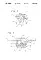
- FIG. 1shows a perspective, partially broken away view of a according to the present invention
- FIG. 2shows a cross sectional view of the mounting device depicted in FIG. 1;
- FIG. 3is a partial side view and section of the mounting device shown FIG. 1;
- FIG. 4show a cross section of a second embodiment of the mounting device shown in FIG. 1;
- FIG. 5shows a cross section of a modification of the embodiment shown in FIGS. 1-3.
- FIGS. 1, 2 and 3Depicted in FIGS. 1, 2 and 3 is a carrier 1 which is connected to a drive device (not shown in the drawing) which is constructed and connected to the carrier such that the carrier 1 can perform a reciprocating movement.
- the carrier 1comprises a planar wall 2 against which a saw-blade 3 can be positioned.
- the saw-blade 3is provided with an opening 4. Although it is recommended that a circular opening be applied, this is in no way necessary; it is possible to use a differently shaped opening.
- a U-shaped bracket 5is fixed to the carrier 1.
- the U-shaped bracketcomprises two side pieces 6, 7 which are placed mutually opposite and which are connected by a back portion 8.
- a back portion 8Arranged in each of the side pieces 6,7 is an opening through which extends a shaft 9.
- the back portioncan also be formed by the carrier 1 if the bracket is formed integrally with the carrier.
- a mounting body 10is fixed on the shaft.
- the bodyis provided with a cavity 11 in which captured a clamping member 12 embodied in the present embodiment as a ball or sphere.
- the mounting bodyis further provided with a protrusion 13.
- the side pieces 6, 7contain identical slots 14 and 15, respectively.
- An actuating rod 16extends through the slots 14, 15.
- sleeves 17are clamped onto both ends of the actuating rod 16.
- the design of the slots 14, 15is such that the actuating rod 16 is always disposed between a contact wall 20 of the body 10 and the protrusion 13 thereof.
- a spring 18 wound from wireis further provided.
- the springextends from the end 19 which abuts the upper side piece 7, to the shaft 9 and is wound approximately one and a half times therearound.
- the springthen extends against the actuating rod 16, is bent downward and again extends along the actuating rod 16 to the shaft 9.
- the spring 18is again wound one and a half times around the shaft 9 and finally ends against the lower side piece 6.
- the winding direction and the dimensions of the springare selected such that the spring exerts a force on the actuating rod 16 such that this rod is urged in the slots 14, 15 towards the carrier 1. Instead of this spring construction it is of course possible to apply other spring configurations.
- the saw-blade 3is introduced from the left-hand side between the sphere 12 and the carrier 1.
- the actuating rod 16is moved manually (by grasping the sleeves 17) counter to the spring pressure, whereby the fixation body 10 with the ball 12 can rotate freely and the saw-blade 3 can be inserted.
- the friction force therebetweenexceeds the moment generated by the saw-blade so that the device can withstand shocks endured by the saw-blade, for example when the saw jams. It is important here that the angle enclosed between the contact wall 20 and the path to be traversed by the actuating rod 16 in the slots 14, 15 be very small, so that the friction force acting between the contact wall 20 and the actuating rod 16 is a normal force. This normal force forms for the greater part a transverse force and is thus absorbed by the right-hand edge of the slots 14 and 15.
- the actuating rod 16only has to be removed manually from the contact surface 20, which is easily done because, as stated, the friction force is a normal force, and the mounting body 11 is easily released. Accordingly, it is then easy to remove the saw-blade simply by grasping the sleeves 17.
- FIG. 4a separate sphere is described which is freely rotatable in the body 11. It is however also possible to fix a protrusion on the mounting body which assumes the function of the sphere.
- a protrusion 21pivotally mounted on the shaft 9.
- the essential differencelies in the fact that the protrusion cannot rotate relative to the body 10; this drawback can be minimized by a suitable design, choice of material and lubrication.
- This embodimentotherwise corresponds with the embodiment shown in FIGS. 1, 2 and 3.
- FIG. 5shows an embodiment wherein the mounting of the saw-blade takes place automatically.
- a lever 22is arranged which is rotatably disposed relative to the U-shaped bracket 5 by means of a shaft 23.
- the bottom slot 14is further provided with an extension 24 into which the actuating rod 16 can be moved.
- One end of the lever 22extends into the vicinity of the carrier 1, while the other end of the lever 22 extends over the extension 24.
- the actuating rod 16is in the extension 24 of the slot 14.
- the mounting body 10is thus unlocked and the saw-blade can be inserted.
- the rod 16When the saw-blade is taken out, the rod 16 is moved manually into the recess 24, whereby the body 10 is released, and the lever 22 is actuated whereby the saw-blade 3 is ejected.
- a spring 25is provided which urges the lever 22 to the position in which the saw-blade is ejected.
Landscapes
- Engineering & Computer Science (AREA)
- Mechanical Engineering (AREA)
- Sawing (AREA)
Abstract
Description
Claims (9)
Applications Claiming Priority (2)
| Application Number | Priority Date | Filing Date | Title |
|---|---|---|---|
| NL9201371 | 1992-07-29 | ||
| NL9201371ANL9201371A (en) | 1992-07-29 | 1992-07-29 | Saw blade fixing device. |
Publications (1)
| Publication Number | Publication Date |
|---|---|
| US5322302Atrue US5322302A (en) | 1994-06-21 |
Family
ID=19861128
Family Applications (1)
| Application Number | Title | Priority Date | Filing Date |
|---|---|---|---|
| US08/098,710Expired - Fee RelatedUS5322302A (en) | 1992-07-29 | 1993-07-28 | Saw-blade fixation device |
Country Status (6)
| Country | Link |
|---|---|
| US (1) | US5322302A (en) |
| EP (1) | EP0582326B1 (en) |
| AU (1) | AU666733B2 (en) |
| CA (1) | CA2100196A1 (en) |
| DE (1) | DE69323451T2 (en) |
| NL (1) | NL9201371A (en) |
Cited By (46)
| Publication number | Priority date | Publication date | Assignee | Title |
|---|---|---|---|---|
| US5443276A (en)* | 1994-07-22 | 1995-08-22 | S-B Power Tool Company | Self-locking blade holder |
| US5573255A (en)* | 1995-05-05 | 1996-11-12 | Power Tool Holders, Inc. | Quick release chuck device for saw blades |
| EP0748665A1 (en)* | 1995-06-09 | 1996-12-18 | Black & Decker Inc. | A reciprocating saw blade clamp |
| US5697279A (en)* | 1995-06-19 | 1997-12-16 | Metabowerke Gmbh & Co. | Apparatus for clamping the end of a saw blade |
| US5722309A (en)* | 1995-01-20 | 1998-03-03 | Metabowerke Gmbh & Co. | Apparatus for clamping the end of a reciprocating saw blade |
| US5724742A (en)* | 1995-07-27 | 1998-03-10 | Black & Decker Inc. | Reciprocating saw blade clamp |
| US5819421A (en)* | 1996-03-01 | 1998-10-13 | Black & Decker Inc. | Powered jig saw |
| US5848474A (en)* | 1996-05-23 | 1998-12-15 | Black & Decker Inc. | Saw blade clamping arrangement for a power tool |
| US5903983A (en)* | 1994-11-29 | 1999-05-18 | Milwaukee Electric Tool Corp. | Keyless clamp assembly for reciprocating tool |
| EP0949032A2 (en) | 1998-04-09 | 1999-10-13 | Black & Decker Inc. | Saw blade clamp arrangement for a power tool |
| US5987758A (en)* | 1997-10-28 | 1999-11-23 | Ryobi North America, Inc. | Quick-change blade clamp |
| US6009627A (en)* | 1995-06-09 | 2000-01-04 | Black & Decker Inc. | Saw blade clamping arrangement for a power tool |
| US6101726A (en)* | 1996-03-01 | 2000-08-15 | Black & Decker Inc. | Saw blade clamp |
| US6112420A (en)* | 1999-08-10 | 2000-09-05 | S-B Power Tool Company | Blade clamp for reciprocating saw |
| US6209208B1 (en) | 1998-10-09 | 2001-04-03 | Milwaukee Electric Tool Corporarion | Keyless blade clamp mechanism |
| US6260281B1 (en)* | 1998-12-24 | 2001-07-17 | Makita Corporation | Blade mounting devices for reciprocating cutting tools |
| US6263979B1 (en) | 1998-07-24 | 2001-07-24 | The Black & Decker Corporation | Interchangeable implement system for power tools |
| US6295736B1 (en) | 1995-06-09 | 2001-10-02 | Black & Decker Inc. | Blade ejection mechanism for a saw blade clamping arrangement of a power tool |
| US6467177B2 (en) | 1998-07-02 | 2002-10-22 | Black & Decker Inc. | Reciprocating saw blade clamp |
| US6530579B1 (en) | 2000-07-11 | 2003-03-11 | Jan P. Houben | Wedging blade clamp for scroll saw |
| US20030132581A1 (en)* | 2002-01-15 | 2003-07-17 | Hitachi Koki Co., Ltd. | Blade attaching and detaching mechanism |
| US6662698B2 (en)* | 2002-01-02 | 2003-12-16 | Black & Decker Inc. | Saw blade clamp system |
| US20040045425A1 (en)* | 2000-10-18 | 2004-03-11 | Houben Jan Peter | Fixing for a saw blade of a jigsaw |
| US20040158994A1 (en)* | 2002-03-08 | 2004-08-19 | Cheng I Teng | Blade clamping device for jig saws |
| US20040163264A1 (en)* | 2003-02-21 | 2004-08-26 | Simonz John C. | Hand saw |
| US20040226177A1 (en)* | 2003-01-13 | 2004-11-18 | Haichun Huan | Blade clamp mechanism |
| US6851193B2 (en)* | 1998-08-13 | 2005-02-08 | Milwaukee Electric Tool Corp | Reciprocating saw |
| US20050039340A1 (en)* | 1995-06-09 | 2005-02-24 | Bigden Jonathan D. | Clamping arrangement for receiving a saw blade in multiple orientations |
| US20050120568A1 (en)* | 2003-10-28 | 2005-06-09 | Mike Wilson | Blade clamp for reciprocating saw |
| US20050156390A1 (en)* | 2004-01-16 | 2005-07-21 | Credo Technology Corporation | Tool-less blade clamping apparatus for a reciprocating tool |
| US20050192585A1 (en)* | 2004-02-27 | 2005-09-01 | Medtronic, Inc. | Surgical saw collet with closed drive ring |
| US6944959B2 (en) | 1995-06-09 | 2005-09-20 | Black & Decker Inc. | Clamping arrangement for receiving a saw blade in multiple orientations |
| US20070131075A1 (en)* | 2005-12-13 | 2007-06-14 | Positec Power Tools (Suzhou) Co. Ltd. | Saw blade clamp mechanism |
| US20070157472A1 (en)* | 2006-01-11 | 2007-07-12 | Cooper Brands, Inc. | Utility knife with releasable blade retention mechanism |
| US7257900B2 (en) | 2002-01-02 | 2007-08-21 | Black & Decker Inc. | Canted saw blade |
| US20070272067A1 (en)* | 2006-05-25 | 2007-11-29 | Yasheng Chen | Blade clamping device |
| US20090025523A1 (en)* | 2007-07-26 | 2009-01-29 | Rexon Industrial Corporation Ltd. | Quick release device for saw blade guard assembly in a circular saw and saw blade guard assembly using the same |
| US20110162212A1 (en)* | 2005-08-02 | 2011-07-07 | Stanley Black & Decker, Inc. | Compact utility knife |
| US20110232107A1 (en)* | 2010-03-25 | 2011-09-29 | Da Graca Gabriel | Pivoting blade retainer |
| US20120074654A1 (en)* | 2010-09-24 | 2012-03-29 | Basso Industry Corp. | Tool having a quick release device |
| US8230607B2 (en) | 2008-05-09 | 2012-07-31 | Milwaukee Electric Tool Corporation | Keyless blade clamp for a power tool |
| US20130247392A1 (en)* | 2012-03-20 | 2013-09-26 | Milwaukee Electric Tool Corporation | Reciprocating saw blade clamp |
| US20140053420A1 (en)* | 2012-08-22 | 2014-02-27 | Makita Corporation | Reciprocating saw |
| US8813373B2 (en) | 2007-09-14 | 2014-08-26 | Milwaukee Electric Tool Corporation | Blade clamp mechanism |
| US20170087649A1 (en)* | 2015-09-24 | 2017-03-30 | Robert Bosch Gmbh | Hand-Guided Stroke-Type Saw having an Untrue-Running Correction Device, and Method for Correction of Untrue Running |
| US20220361934A1 (en)* | 2021-05-13 | 2022-11-17 | DePuy Synthes Products, Inc. | Surgical impacting tool interfaces |
Families Citing this family (7)
| Publication number | Priority date | Publication date | Assignee | Title |
|---|---|---|---|---|
| GB9425721D0 (en)* | 1994-12-20 | 1995-02-22 | Black & Decker Inc | A saw blade clamp |
| DE19737237B4 (en)* | 1997-08-27 | 2005-09-08 | Scintilla Ag | Clamping device for saw blades |
| NL1008507C2 (en)* | 1998-03-06 | 1999-09-07 | Skil Europ Bv | Clamping device for a saw blade and saw equipped with it. |
| US20030121389A1 (en) | 2002-01-02 | 2003-07-03 | Wheeler Thomas J. | Reciprocating saw |
| US9321112B2 (en) | 2011-05-18 | 2016-04-26 | Black & Decker Inc. | Power saw tool |
| CN103394755B (en)* | 2013-08-02 | 2015-10-14 | 铁鎯电动工具有限公司 | Saw blade clamping device and reciprocating saw thereof |
| US9559628B2 (en) | 2013-10-25 | 2017-01-31 | Black & Decker Inc. | Handheld power tool with compact AC switch |
Citations (4)
| Publication number | Priority date | Publication date | Assignee | Title |
|---|---|---|---|---|
| US3555678A (en)* | 1968-01-23 | 1971-01-19 | Gen Appliance Corp | Electric culinary device |
| FR2257376A1 (en)* | 1974-01-11 | 1975-08-08 | Skil Nederland Nv | |
| US4106181A (en)* | 1976-08-09 | 1978-08-15 | American Safety Equipment Corporation | Quick release mechanism for oscillating saw blade |
| US4601477A (en)* | 1985-01-10 | 1986-07-22 | The Singer Company | Sabre saw blade clamp |
- 1992
- 1992-07-29NLNL9201371Apatent/NL9201371A/ennot_activeApplication Discontinuation
- 1993
- 1993-06-28DEDE69323451Tpatent/DE69323451T2/ennot_activeExpired - Fee Related
- 1993-06-28EPEP93201865Apatent/EP0582326B1/ennot_activeExpired - Lifetime
- 1993-07-02AUAU41731/93Apatent/AU666733B2/ennot_activeCeased
- 1993-07-09CACA002100196Apatent/CA2100196A1/ennot_activeAbandoned
- 1993-07-28USUS08/098,710patent/US5322302A/ennot_activeExpired - Fee Related
Patent Citations (4)
| Publication number | Priority date | Publication date | Assignee | Title |
|---|---|---|---|---|
| US3555678A (en)* | 1968-01-23 | 1971-01-19 | Gen Appliance Corp | Electric culinary device |
| FR2257376A1 (en)* | 1974-01-11 | 1975-08-08 | Skil Nederland Nv | |
| US4106181A (en)* | 1976-08-09 | 1978-08-15 | American Safety Equipment Corporation | Quick release mechanism for oscillating saw blade |
| US4601477A (en)* | 1985-01-10 | 1986-07-22 | The Singer Company | Sabre saw blade clamp |
Cited By (78)
| Publication number | Priority date | Publication date | Assignee | Title |
|---|---|---|---|---|
| EP0693341A1 (en) | 1994-07-22 | 1996-01-24 | S-B Power Tool Company | Self-locking blade holder |
| US5443276A (en)* | 1994-07-22 | 1995-08-22 | S-B Power Tool Company | Self-locking blade holder |
| US6237231B1 (en) | 1994-11-29 | 2001-05-29 | Milwaukee Electric Tool Corporation | Keyless clamp assembly for reciprocating tool |
| US5903983A (en)* | 1994-11-29 | 1999-05-18 | Milwaukee Electric Tool Corp. | Keyless clamp assembly for reciprocating tool |
| US5722309A (en)* | 1995-01-20 | 1998-03-03 | Metabowerke Gmbh & Co. | Apparatus for clamping the end of a reciprocating saw blade |
| US5573255A (en)* | 1995-05-05 | 1996-11-12 | Power Tool Holders, Inc. | Quick release chuck device for saw blades |
| US20080072438A1 (en)* | 1995-06-09 | 2008-03-27 | Bigden Jonathan D | Clamping arrangement for receiving a saw blade in multiple orientations |
| US5647133A (en)* | 1995-06-09 | 1997-07-15 | Black & Decker Inc. | Saw blade clamping arrangement for a power tool |
| US5794352A (en)* | 1995-06-09 | 1998-08-18 | Black & Decker Inc. | Saw blade clamping arrangement for a power tool |
| US6502317B2 (en) | 1995-06-09 | 2003-01-07 | Black & Decker Inc. | Blade ejection mechanism for a saw blade clamping arrangement of a power tool |
| EP0748665A1 (en)* | 1995-06-09 | 1996-12-18 | Black & Decker Inc. | A reciprocating saw blade clamp |
| US6295736B1 (en) | 1995-06-09 | 2001-10-02 | Black & Decker Inc. | Blade ejection mechanism for a saw blade clamping arrangement of a power tool |
| US20050039340A1 (en)* | 1995-06-09 | 2005-02-24 | Bigden Jonathan D. | Clamping arrangement for receiving a saw blade in multiple orientations |
| US6944959B2 (en) | 1995-06-09 | 2005-09-20 | Black & Decker Inc. | Clamping arrangement for receiving a saw blade in multiple orientations |
| US6009627A (en)* | 1995-06-09 | 2000-01-04 | Black & Decker Inc. | Saw blade clamping arrangement for a power tool |
| US6023848A (en)* | 1995-06-09 | 2000-02-15 | Black & Decker Inc. | Saw blade clamping arrangement for a power tool |
| US7003888B2 (en) | 1995-06-09 | 2006-02-28 | Black & Decker Inc. | Clamping arrangement for receiving a saw blade |
| US7325315B2 (en) | 1995-06-09 | 2008-02-05 | Black & Decker Inc. | Clamping arrangement for receiving a saw blade in multiple orientations |
| US8046926B2 (en) | 1995-06-09 | 2011-11-01 | Black & Decker Inc. | Clamping arrangement for receiving a saw blade in multiple orientations |
| US5697279A (en)* | 1995-06-19 | 1997-12-16 | Metabowerke Gmbh & Co. | Apparatus for clamping the end of a saw blade |
| US5724742A (en)* | 1995-07-27 | 1998-03-10 | Black & Decker Inc. | Reciprocating saw blade clamp |
| US6101726A (en)* | 1996-03-01 | 2000-08-15 | Black & Decker Inc. | Saw blade clamp |
| US5819421A (en)* | 1996-03-01 | 1998-10-13 | Black & Decker Inc. | Powered jig saw |
| US5848474A (en)* | 1996-05-23 | 1998-12-15 | Black & Decker Inc. | Saw blade clamping arrangement for a power tool |
| US5987758A (en)* | 1997-10-28 | 1999-11-23 | Ryobi North America, Inc. | Quick-change blade clamp |
| EP0949032A2 (en) | 1998-04-09 | 1999-10-13 | Black & Decker Inc. | Saw blade clamp arrangement for a power tool |
| US6467177B2 (en) | 1998-07-02 | 2002-10-22 | Black & Decker Inc. | Reciprocating saw blade clamp |
| US6263979B1 (en) | 1998-07-24 | 2001-07-24 | The Black & Decker Corporation | Interchangeable implement system for power tools |
| US7188425B2 (en) | 1998-08-13 | 2007-03-13 | Milwaukee Electric Tool Corporation | Reciprocating saw |
| US20050132583A1 (en)* | 1998-08-13 | 2005-06-23 | Milwaukee Electric Tool Corporation | Reciprocating saw |
| US6851193B2 (en)* | 1998-08-13 | 2005-02-08 | Milwaukee Electric Tool Corp | Reciprocating saw |
| US6209208B1 (en) | 1998-10-09 | 2001-04-03 | Milwaukee Electric Tool Corporarion | Keyless blade clamp mechanism |
| US6260281B1 (en)* | 1998-12-24 | 2001-07-17 | Makita Corporation | Blade mounting devices for reciprocating cutting tools |
| US6112420A (en)* | 1999-08-10 | 2000-09-05 | S-B Power Tool Company | Blade clamp for reciprocating saw |
| US6530579B1 (en) | 2000-07-11 | 2003-03-11 | Jan P. Houben | Wedging blade clamp for scroll saw |
| US20040045425A1 (en)* | 2000-10-18 | 2004-03-11 | Houben Jan Peter | Fixing for a saw blade of a jigsaw |
| US7257900B2 (en) | 2002-01-02 | 2007-08-21 | Black & Decker Inc. | Canted saw blade |
| CN1429679B (en)* | 2002-01-02 | 2012-07-11 | 布莱克和戴克公司 | Saw blade clamping device and system, and a series of saw blades used for clamping device |
| US6662698B2 (en)* | 2002-01-02 | 2003-12-16 | Black & Decker Inc. | Saw blade clamp system |
| US6893026B2 (en)* | 2002-01-15 | 2005-05-17 | Hitachi Koki Co., Ltd. | Blade attaching and detaching mechanism |
| US20030132581A1 (en)* | 2002-01-15 | 2003-07-17 | Hitachi Koki Co., Ltd. | Blade attaching and detaching mechanism |
| US20040158994A1 (en)* | 2002-03-08 | 2004-08-19 | Cheng I Teng | Blade clamping device for jig saws |
| US20040226177A1 (en)* | 2003-01-13 | 2004-11-18 | Haichun Huan | Blade clamp mechanism |
| US6854187B2 (en)* | 2003-01-13 | 2005-02-15 | Positec Power Tools (Suzhou) Co., Ltd | Blade clamp mechanism |
| US20040163264A1 (en)* | 2003-02-21 | 2004-08-26 | Simonz John C. | Hand saw |
| US8327550B2 (en)* | 2003-10-28 | 2012-12-11 | Black & Decker Inc. | Blade clamp for reciprocating saw |
| US20050120568A1 (en)* | 2003-10-28 | 2005-06-09 | Mike Wilson | Blade clamp for reciprocating saw |
| US20110131819A1 (en)* | 2003-10-28 | 2011-06-09 | Black And Decker Inc. | Blade clamp for reciprocating saw |
| US20050156390A1 (en)* | 2004-01-16 | 2005-07-21 | Credo Technology Corporation | Tool-less blade clamping apparatus for a reciprocating tool |
| US7871080B2 (en) | 2004-01-16 | 2011-01-18 | Robert Bosch Gmbh | Tool-less blade clamping apparatus for a reciprocating tool |
| US20110074122A1 (en)* | 2004-01-16 | 2011-03-31 | Robert Bosch Tool Corporation | Tool-less blade clamping apparatus for a reciprocating tool |
| US8641049B2 (en) | 2004-01-16 | 2014-02-04 | Robert Bosch Gmbh | Tool-less blade clamping apparatus for a reciprocating tool |
| US8393625B2 (en) | 2004-01-16 | 2013-03-12 | Robert Bosch Gmbh | Tool-less blade clamping apparatus for a reciprocating tool |
| US20050192585A1 (en)* | 2004-02-27 | 2005-09-01 | Medtronic, Inc. | Surgical saw collet with closed drive ring |
| US8549755B2 (en)* | 2005-08-02 | 2013-10-08 | Stanley Black & Decker, Inc. | Compact utility knife |
| US20110162212A1 (en)* | 2005-08-02 | 2011-07-07 | Stanley Black & Decker, Inc. | Compact utility knife |
| US20070131075A1 (en)* | 2005-12-13 | 2007-06-14 | Positec Power Tools (Suzhou) Co. Ltd. | Saw blade clamp mechanism |
| US20070157472A1 (en)* | 2006-01-11 | 2007-07-12 | Cooper Brands, Inc. | Utility knife with releasable blade retention mechanism |
| US20070272067A1 (en)* | 2006-05-25 | 2007-11-29 | Yasheng Chen | Blade clamping device |
| US7784388B2 (en)* | 2006-05-25 | 2010-08-31 | Chervon Limited | Blade clamping device |
| US8104386B2 (en)* | 2007-07-26 | 2012-01-31 | Rexon Industrial Corporation Ltd. | Quick release device for saw blade guard assembly in a circular saw and saw blade guard assembly using the same |
| US20090025523A1 (en)* | 2007-07-26 | 2009-01-29 | Rexon Industrial Corporation Ltd. | Quick release device for saw blade guard assembly in a circular saw and saw blade guard assembly using the same |
| US8813372B2 (en) | 2007-09-14 | 2014-08-26 | Milwaukee Electric Tool Corporation | Blade clamp mechanism |
| US8813373B2 (en) | 2007-09-14 | 2014-08-26 | Milwaukee Electric Tool Corporation | Blade clamp mechanism |
| US8230607B2 (en) | 2008-05-09 | 2012-07-31 | Milwaukee Electric Tool Corporation | Keyless blade clamp for a power tool |
| US8826549B2 (en) | 2010-03-25 | 2014-09-09 | Black & Decker Inc. | Pivoting blade retainer |
| US8555516B2 (en)* | 2010-03-25 | 2013-10-15 | Black & Decker Inc. | Pivoting blade retainer |
| US20110232107A1 (en)* | 2010-03-25 | 2011-09-29 | Da Graca Gabriel | Pivoting blade retainer |
| US9186735B2 (en) | 2010-03-25 | 2015-11-17 | Black & Decker Inc. | Pivoting blade retainer |
| US20120074654A1 (en)* | 2010-09-24 | 2012-03-29 | Basso Industry Corp. | Tool having a quick release device |
| US20130247392A1 (en)* | 2012-03-20 | 2013-09-26 | Milwaukee Electric Tool Corporation | Reciprocating saw blade clamp |
| US9156097B2 (en)* | 2012-03-20 | 2015-10-13 | Milwaukee Electric Tool Corporation | Reciprocating saw blade clamp |
| US20140053420A1 (en)* | 2012-08-22 | 2014-02-27 | Makita Corporation | Reciprocating saw |
| US9205502B2 (en)* | 2012-08-22 | 2015-12-08 | Makita Corporation | Reciprocating saw |
| US20170087649A1 (en)* | 2015-09-24 | 2017-03-30 | Robert Bosch Gmbh | Hand-Guided Stroke-Type Saw having an Untrue-Running Correction Device, and Method for Correction of Untrue Running |
| US10086450B2 (en)* | 2015-09-24 | 2018-10-02 | Robert Bosch Gmbh | Hand-guided stroke-type saw having an untrue-running correction device, and method for correction of untrue running |
| US20220361934A1 (en)* | 2021-05-13 | 2022-11-17 | DePuy Synthes Products, Inc. | Surgical impacting tool interfaces |
| US12102369B2 (en)* | 2021-05-13 | 2024-10-01 | DePuy Synthes Products, Inc. | Surgical impacting tool interfaces |
Also Published As
| Publication number | Publication date |
|---|---|
| DE69323451D1 (en) | 1999-03-25 |
| DE69323451T2 (en) | 1999-06-24 |
| EP0582326B1 (en) | 1999-02-10 |
| NL9201371A (en) | 1994-02-16 |
| AU4173193A (en) | 1994-02-03 |
| AU666733B2 (en) | 1996-02-22 |
| EP0582326A1 (en) | 1994-02-09 |
| CA2100196A1 (en) | 1994-01-30 |
Similar Documents
| Publication | Publication Date | Title |
|---|---|---|
| US5322302A (en) | Saw-blade fixation device | |
| US4601477A (en) | Sabre saw blade clamp | |
| EP0554929B1 (en) | Blade collet | |
| US5987758A (en) | Quick-change blade clamp | |
| US6101726A (en) | Saw blade clamp | |
| EP0980299B1 (en) | Adjustable clamping jaw | |
| US6648314B1 (en) | Eccentric clamp clip | |
| US5632089A (en) | Saber saw assembly with improved vising mechanism | |
| US8327550B2 (en) | Blade clamp for reciprocating saw | |
| US4390047A (en) | Tool for strap tensioning and cutting | |
| JP2000501825A (en) | Fulcrum clamp | |
| EP0655298A1 (en) | Bar clamp | |
| US5000232A (en) | Manual band installation tool | |
| EP0930121A2 (en) | Blade mounting device in cutting tool | |
| KR102663344B1 (en) | Wedge type tension clamp | |
| US5758403A (en) | Impact tool wire-insertion head having selective cut/no cut blade configuration | |
| CA2022519A1 (en) | Rapid jaw adjustment for tools and the like | |
| JP3909074B2 (en) | Tension spring clip with tension springs symmetrical to each other | |
| US6101906A (en) | Adjustable spanner having releasable engagement securing mechanism | |
| GB2311485A (en) | Tile cutter of hole cutting type | |
| EP0777057A1 (en) | Improved clamp | |
| JP2545567B2 (en) | Holding part for accessory | |
| US20060005366A1 (en) | Brake clip removal tool | |
| GB2289006A (en) | Setting tool | |
| JPS6314000Y2 (en) |
Legal Events
| Date | Code | Title | Description |
|---|---|---|---|
| AS | Assignment | Owner name:SKIL EUROPE B.V., NETHERLANDS Free format text:ASSIGNMENT OF ASSIGNORS INTEREST;ASSIGNOR:QUIRIJNEN, ANTONIUS JACOBUS JOHANNUS;REEL/FRAME:006643/0344 Effective date:19930718 | |
| FPAY | Fee payment | Year of fee payment:4 | |
| FEPP | Fee payment procedure | Free format text:PETITION RELATED TO MAINTENANCE FEES FILED (ORIGINAL EVENT CODE: PMFP); ENTITY STATUS OF PATENT OWNER: LARGE ENTITY | |
| REMI | Maintenance fee reminder mailed | ||
| REIN | Reinstatement after maintenance fee payment confirmed | ||
| FP | Lapsed due to failure to pay maintenance fee | Effective date:20020621 | |
| FEPP | Fee payment procedure | Free format text:PETITION RELATED TO MAINTENANCE FEES GRANTED (ORIGINAL EVENT CODE: PMFG); ENTITY STATUS OF PATENT OWNER: LARGE ENTITY | |
| FPAY | Fee payment | Year of fee payment:8 | |
| SULP | Surcharge for late payment | ||
| PRDP | Patent reinstated due to the acceptance of a late maintenance fee | Effective date:20030123 | |
| FEPP | Fee payment procedure | Free format text:PAYOR NUMBER ASSIGNED (ORIGINAL EVENT CODE: ASPN); ENTITY STATUS OF PATENT OWNER: LARGE ENTITY | |
| REMI | Maintenance fee reminder mailed | ||
| LAPS | Lapse for failure to pay maintenance fees | ||
| LAPS | Lapse for failure to pay maintenance fees | Free format text:PATENT EXPIRED FOR FAILURE TO PAY MAINTENANCE FEES (ORIGINAL EVENT CODE: EXP.); ENTITY STATUS OF PATENT OWNER: LARGE ENTITY | |
| STCH | Information on status: patent discontinuation | Free format text:PATENT EXPIRED DUE TO NONPAYMENT OF MAINTENANCE FEES UNDER 37 CFR 1.362 | |
| FP | Lapsed due to failure to pay maintenance fee | Effective date:20060621 |