US5321582A - Electronic component heat sink attachment using a low force spring - Google Patents
Electronic component heat sink attachment using a low force springDownload PDFInfo
- Publication number
- US5321582A US5321582AUS08/051,661US5166193AUS5321582AUS 5321582 AUS5321582 AUS 5321582AUS 5166193 AUS5166193 AUS 5166193AUS 5321582 AUS5321582 AUS 5321582A
- Authority
- US
- United States
- Prior art keywords
- housing
- carrier
- heat sink
- electronic component
- wall surface
- Prior art date
- Legal status (The legal status is an assumption and is not a legal conclusion. Google has not performed a legal analysis and makes no representation as to the accuracy of the status listed.)
- Expired - Lifetime
Links
- 239000000463materialSubstances0.000claimsdescription4
- 239000000969carrierSubstances0.000claims1
- 238000000034methodMethods0.000description4
- 238000004519manufacturing processMethods0.000description2
- 238000012986modificationMethods0.000description2
- 230000004048modificationEffects0.000description2
- 229910052582BNInorganic materials0.000description1
- PZNSFCLAULLKQX-UHFFFAOYSA-NBoron nitrideChemical compoundN#BPZNSFCLAULLKQX-UHFFFAOYSA-N0.000description1
- 230000006835compressionEffects0.000description1
- 238000007906compressionMethods0.000description1
- 230000001351cycling effectEffects0.000description1
- 238000006073displacement reactionMethods0.000description1
- 230000000694effectsEffects0.000description1
- 229920001721polyimidePolymers0.000description1
- 229910052710siliconInorganic materials0.000description1
- 239000010703siliconSubstances0.000description1
Images


Classifications
- H—ELECTRICITY
- H05—ELECTRIC TECHNIQUES NOT OTHERWISE PROVIDED FOR
- H05K—PRINTED CIRCUITS; CASINGS OR CONSTRUCTIONAL DETAILS OF ELECTRIC APPARATUS; MANUFACTURE OF ASSEMBLAGES OF ELECTRICAL COMPONENTS
- H05K7/00—Constructional details common to different types of electric apparatus
- H05K7/20—Modifications to facilitate cooling, ventilating, or heating
- H05K7/2039—Modifications to facilitate cooling, ventilating, or heating characterised by the heat transfer by conduction from the heat generating element to a dissipating body
- H05K7/20436—Inner thermal coupling elements in heat dissipating housings, e.g. protrusions or depressions integrally formed in the housing
- H05K7/2049—Pressing means used to urge contact, e.g. springs
- H—ELECTRICITY
- H01—ELECTRIC ELEMENTS
- H01L—SEMICONDUCTOR DEVICES NOT COVERED BY CLASS H10
- H01L2924/00—Indexing scheme for arrangements or methods for connecting or disconnecting semiconductor or solid-state bodies as covered by H01L24/00
- H01L2924/0001—Technical content checked by a classifier
- H01L2924/0002—Not covered by any one of groups H01L24/00, H01L24/00 and H01L2224/00
Definitions
- This inventionrelates to the attachment of printed circuit board mounted, heat generating electrical components to heat sinks.
- the attachment to such electrical componentswhich have heat transfer tabs to heat sink housings using spring type members.
- primary objects of the present inventioninvolve the provision of an attachment between numerous types of power generating electrical devices and a housing which also serves as a heat sink while:
- a thermal attachment assemblyfor heat generating electronic devices which includes a multi-element spring having low force, high deflection, spring fingers, and which is adjustable and attached by screws to a cover to apply pressure directly against electronic components arranged generally perpendicular to at least one edge of a printed wired board (PWB).
- the attachment assemblyincludes a heat sink housing in which electronic components are pressed against an electrically insulating, thermally conductive film positioned against one wall of the heat sink housing.
- the PWBis snapped to a carrier and both are placed into the housing so that the electronic devices are positioned within the spaces of the carrier.
- the carrierincludes sloping surfaces, so that the spring fingers are deflected away from the electronic device when the cover is attached to the housing, thereby insuring that the spring fingers are properly positioned onto the electronic devices, between the spaces of the carrier.
- the adjustable positioning capability of the spring fingersenables the assembly to tolerate dimensional variations in the individual parts of the assembly, such as the housing, film, electronic devices, cover, and the springs.
- the electronic devicesmay be located along only one side or both sides of the PWB.
- FIG. 1shows a preferred embodiment of an attachment in accordance with the present invention in partial cross section
- FIG. 2is a cross-sectional view of an assembly in which a pair of attachment devices of the type shown in FIG. 1 are provided to balance each other;
- FIG. 3is an exploded view of the assembly shown in FIG. 2;
- FIG. 4is a cross-sectional view of an assembly in which the force of a single attachment device of the type shown in FIG. 1 is balanced by the provision of a surface on the cover which abuts a surface of the housing which is in opposition to the attachment device.
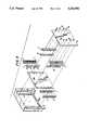
- FIG. 1shows a preferred embodiment of an attachment in accordance with the present invention in which a housing 1 serves as a heat sink for at least one power generating electronic component 3, such as a TO220, that is provided with a body portion 3a from which a heat transfer tab 3b and leads 3c extend.
- a mounting hole 5is provided in the heat transfer tab 3b to enable it to be snapped between hooks 7a, 7b and hung on the hook 7a of a carrier 7.
- the leads 3c of the electronic component 3are S-shaped to minimize the force required to move the body portion 3a of the component 3 flush against an electrically insulative, thermally conductive film 9 and to minimize the stresses in the leads 3c after this displacement has been produced.
- the electrically insulative, thermally conductive film 9is formed of, for example, polyimide film beneath a layer of boron-nitride filled silicon as is sold by Chomerics, Inc. under the trademark CHO-THERM 1680, which will efficiently transfer heat away from mounted components without requiring a high clamping pressure. Furthermore, the film 9 is, preferably, adhesive-backed, as is the noted Chomerics product, so that it can be easily mounted to wall 1a of housing 1. The film 9 is provided with slot-shaped cutouts that are matched to slot-like recesses 1b that are formed in the housing wall 1a to receive the hooks 7a, 7b of the carrier 7.
- the multi-element spring 11comprises a plurality of spring fingers 11a that are connected to a mounting strip 11b, which is attached to a housing cover 14 via screws 16 and a bar nut 18.
- the spacing of the fingers 11ais matched to the locations at which the tabs 3b of the electronic components 3 are snapped onto the hooks 7a and 7b.
- spring fingers 11aneed only exert a force which is the sum of the required pressure on the film 9 (e.g., 20-50 psi) divided by the surface area of the body portion 3a and tab portion 3b of component 3 that engages the film 9, plus the force required to move the electronic component 3 to the wall 1a of the housing 1.
- the carrier 7has vertical legs 7c which define spaces within which the body portion 3a of the components 3 can be received when hung on the hooks 7a. Some of the legs 7c have arms 7d from which a snap plug 7e projects. Snap plugs 7e are used to attach the carrier 7 to a printed wiring board (PWB, i.e., a printed circuit board without active components) at the correct location, by being snapped into openings formed in the PWB.
- PWBprinted wiring board
- the carrier 7,also, includes sloping surfaces 7f which serve to deflect the spring fingers 11a rightward, when the cover is attached to the housing, thereby insuring that the spring fingers 11a are properly positioned onto the electronic components 3, in the spaces between legs 7c of the carrier 7.
- ribs 7gcan be located on the sloping surfaces of the carrier, at points corresponding to the spaces between the spring fingers 11a, to facilitate assembly by aiding in the positioning of the spring/cover assembly (formed of housing cover 14 and spring 11 attached thereto) on the carrier 7, and providing tactile feedback if assembled manually. Furthermore, the downward force of the spring fingers 11a is transferred by the sloping surfaces 7f, through the hooks 7a, to the bottom 1c of the recesses 1b, on which the hooks 7a rest after the carrier has been lowered into the housing 1 and snapped into the PWB, so that stressing of the leads 3c of the components 3 during assembly is avoided.
- the force that the multi-element spring 11 generatesmust be counterbalanced by an equal and opposite force.
- this counterbalancingis achieved by providing a multi-element springs 11 at each of opposite sides of the cover so that their spring fingers 11a balance each other.
- an abutment member 20is utilized to provide the necessary counterbalancing effect.
- Abutment member 20may be attached to the cover so that its side surface abuts the inner wall of the housing 1 when the cover is in place, or it may be attached to the inner wall of the housing 1 so as to engage in a complementarily-shaped recess in the cover when the cover is in place.
- the present inventionwill find a wide range of application to devices in which various electronic components, which generate amounts of heat which cannot be adequately dissipated without using a heat sink, are enclosed in a housing.
Landscapes
- Physics & Mathematics (AREA)
- Thermal Sciences (AREA)
- Engineering & Computer Science (AREA)
- Microelectronics & Electronic Packaging (AREA)
- Cooling Or The Like Of Semiconductors Or Solid State Devices (AREA)
- Cooling Or The Like Of Electrical Apparatus (AREA)
Abstract
Description
1. Field of the Invention
This invention relates to the attachment of printed circuit board mounted, heat generating electrical components to heat sinks. In particular, to the attachment to such electrical components which have heat transfer tabs to heat sink housings using spring type members.
2. Description of Related Art
One method by which tabbed printed circuit board mounted, heat generating electrical components have been attached to heat sinks has involved individually attaching each device to the heat sink with a screw through the hole in the tab of the electronic device, and utilizing an electrically insulating thermally conductive film between the heat sink and the device tab. A nut is tightened onto the screw to provide the compressive force required to provide adequate compression of the film to maximize heat transfer from the device to the heat sink through the film. There are many variations of this technique, such as using a threaded hole in the heat sink rather than a nut. Problems arise with this general manner of attachment because the tension created by the screw may be relieved by material creep in the insulating washer or grommet, or the screw may back out under certain operating conditions, such as where the device is subject to vibration or temperature cycling. Another disadvantage is that the large number of parts that must be manually assembled when there are a number of heat generating components in an assembly, and it is difficult to automate the production of such attachments for high volume manufacturing.
In addition to the various uses of attachment screws, numerous attachment techniques have been developed which use spring members. A number of these attachments use clips with multiple spring fingers, as can be seen by reference to U.S. Pat. Nos. 4,922,601; 4,891,735; 4,872,089; 4,845,590; and 4,707,726, for example. Difficulties are encountered with these techniques for various reasons. To achieve a compact assembly, the springs must achieve high forces at low deflections, and this means that the springs must be manufactured specifically for an individual device and changing the device may cause the spring to exert too much or too little force since stiff springs have force constants which create a very narrow range of deflections within which the proper pressure will be applied. Furthermore, there is often a need for special tools to insure that the device or the spring is not damaged during assembly. Historically, electrically insulating and thermally conductive pads require 300-500 psi for effective heat transfer; but this requires a material to be disposed between the spring and the device to distribute the spring force on the device, to prevent the spring from damaging the device. Some arrangements require that the heat sink be a separate part from the housing, and others require numerous unique parts that need to be manually assembled.
Thus, there is a need for a heat sink attachment which will enable the use of low force springs in order to increase the range of permissible spring deflections, thereby increasing the tolerances and the variety of heat sinks which may be attached, and to eliminate the need for intervening materials for distributing the spring force. Additionally, a need also exists for an arrangement which will not require numerous parts that require manual assembly.
In keeping with the foregoing, primary objects of the present invention involve the provision of an attachment between numerous types of power generating electrical devices and a housing which also serves as a heat sink while:
minimizing the number of parts required;
facilitating manual or automated assembly;
achieving a minimal packaged volume; and
accepting of parts with a greater degree of dimensional tolerance.
These and other objects of the present invention are achieved by a thermal attachment assembly for heat generating electronic devices which includes a multi-element spring having low force, high deflection, spring fingers, and which is adjustable and attached by screws to a cover to apply pressure directly against electronic components arranged generally perpendicular to at least one edge of a printed wired board (PWB). Specifically, the attachment assembly includes a heat sink housing in which electronic components are pressed against an electrically insulating, thermally conductive film positioned against one wall of the heat sink housing. The PWB is snapped to a carrier and both are placed into the housing so that the electronic devices are positioned within the spaces of the carrier. The carrier includes sloping surfaces, so that the spring fingers are deflected away from the electronic device when the cover is attached to the housing, thereby insuring that the spring fingers are properly positioned onto the electronic devices, between the spaces of the carrier.
Ribs located on the sloped portion of the carrier, at points corresponding to the spaces between the spring fingers, facilitate manual assembly by aiding in the positioning of the spring/cover assembly on the carrier. The adjustable positioning capability of the spring fingers enables the assembly to tolerate dimensional variations in the individual parts of the assembly, such as the housing, film, electronic devices, cover, and the springs. The electronic devices may be located along only one side or both sides of the PWB.
These and further objects, features and advantages of the present invention will become apparent from the following description when taken in connection with the accompanying drawings which, for purposes of illustration only, show several embodiments in accordance with the present invention.
FIG. 1 shows a preferred embodiment of an attachment in accordance with the present invention in partial cross section;
FIG. 2 is a cross-sectional view of an assembly in which a pair of attachment devices of the type shown in FIG. 1 are provided to balance each other;
FIG. 3 is an exploded view of the assembly shown in FIG. 2; and
FIG. 4 is a cross-sectional view of an assembly in which the force of a single attachment device of the type shown in FIG. 1 is balanced by the provision of a surface on the cover which abuts a surface of the housing which is in opposition to the attachment device.
FIG. 1 shows a preferred embodiment of an attachment in accordance with the present invention in which a housing 1 serves as a heat sink for at least one power generating electronic component 3, such as a TO220, that is provided with abody portion 3a from which a heat transfer tab 3b and leads 3c extend. A mounting hole 5 is provided in the heat transfer tab 3b to enable it to be snapped betweenhooks 7a, 7b and hung on the hook 7a of a carrier 7. Theleads 3c of the electronic component 3 are S-shaped to minimize the force required to move thebody portion 3a of the component 3 flush against an electrically insulative, thermally conductive film 9 and to minimize the stresses in theleads 3c after this displacement has been produced.
The electrically insulative, thermally conductive film 9 is formed of, for example, polyimide film beneath a layer of boron-nitride filled silicon as is sold by Chomerics, Inc. under the trademark CHO-THERM 1680, which will efficiently transfer heat away from mounted components without requiring a high clamping pressure. Furthermore, the film 9 is, preferably, adhesive-backed, as is the noted Chomerics product, so that it can be easily mounted to wall 1a of housing 1. The film 9 is provided with slot-shaped cutouts that are matched to slot-like recesses 1b that are formed in the housing wall 1a to receive thehooks 7a, 7b of the carrier 7.
To apply thebody portion 3a of the electronic component against the film 9, a multi-element spring 11 is provided. The multi-element spring 11, as shown in FIG. 3, comprises a plurality of spring fingers 11a that are connected to a mounting strip 11b, which is attached to ahousing cover 14 via screws 16 and a bar nut 18. The spacing of the fingers 11a is matched to the locations at which the tabs 3b of the electronic components 3 are snapped onto thehooks 7a and 7b. These spring fingers 11a need only exert a force which is the sum of the required pressure on the film 9 (e.g., 20-50 psi) divided by the surface area of thebody portion 3a and tab portion 3b of component 3 that engages the film 9, plus the force required to move the electronic component 3 to the wall 1a of the housing 1.
The carrier 7 has vertical legs 7c which define spaces within which thebody portion 3a of the components 3 can be received when hung on the hooks 7a. Some of the legs 7c have arms 7d from which a snap plug 7e projects. Snap plugs 7e are used to attach the carrier 7 to a printed wiring board (PWB, i.e., a printed circuit board without active components) at the correct location, by being snapped into openings formed in the PWB. The carrier 7, also, includes sloping surfaces 7f which serve to deflect the spring fingers 11a rightward, when the cover is attached to the housing, thereby insuring that the spring fingers 11a are properly positioned onto the electronic components 3, in the spaces between legs 7c of the carrier 7. Additionally, ribs 7g can be located on the sloping surfaces of the carrier, at points corresponding to the spaces between the spring fingers 11a, to facilitate assembly by aiding in the positioning of the spring/cover assembly (formed ofhousing cover 14 and spring 11 attached thereto) on the carrier 7, and providing tactile feedback if assembled manually. Furthermore, the downward force of the spring fingers 11a is transferred by the sloping surfaces 7f, through the hooks 7a, to the bottom 1c of the recesses 1b, on which the hooks 7a rest after the carrier has been lowered into the housing 1 and snapped into the PWB, so that stressing of theleads 3c of the components 3 during assembly is avoided.
The force that the multi-element spring 11 generates must be counterbalanced by an equal and opposite force. In FIGS. 2 & 3, this counterbalancing is achieved by providing a multi-element springs 11 at each of opposite sides of the cover so that their spring fingers 11a balance each other. Alternatively, as shown in the embodiment of FIG. 4, where only a single row of spring fingers is utilized to act on components on one side of the housing 1, anabutment member 20 is utilized to provide the necessary counterbalancing effect.Abutment member 20 may be attached to the cover so that its side surface abuts the inner wall of the housing 1 when the cover is in place, or it may be attached to the inner wall of the housing 1 so as to engage in a complementarily-shaped recess in the cover when the cover is in place.
While I have shown and described various embodiments in accordance with the present invention, it is understood that the same is not limited thereto, but is susceptible of numerous changes and modifications as known to those skilled in the art, and we, therefore, do not wish to be limited to the details shown and described herein, but intend to cover all such changes and modifications as are encompassed by the scope of the appended claims.
The present invention will find a wide range of application to devices in which various electronic components, which generate amounts of heat which cannot be adequately dissipated without using a heat sink, are enclosed in a housing.
Claims (10)
1. Electronic component heat sink arrangement comprising a housing formed of a heat sinking material and containing a printed circuit wiring board and a plurality of heat generating electronic components, at least one carrier upon which said electronic components are supported and which is attached to said printed circuit wiring board, a cover panel closing an open end of the housing, and at least one spring member having a plurality of spring fingers pressing the electronic components into a nonelectrically conductive, heat exchange relationship with an inner wall surface of the housing; wherein a heat conductive, electrically insulating film is disposed between the electronic components and the inner wall surface of the housing; wherein said at least one spring member is mounted to an inner side of the cover panel; and wherein said at least one carrier has a deflection surface means for deflecting the spring fingers so as to prevent them from pressing down on the electronic components as the cover is being positioned onto the housing and which permits the spring fingers to freely engage a side of the electronic components once the cover is in position closing the open end of the housing.
2. Electronic component heat sink arrangement according to claim 1, wherein said spring fingers are constructed to apply a pressure in a range of 20-50 psi to a full range of differing sizes of electronic components supportable on said at least one carrier when engaged on the side thereof with the cover closing the housing.
3. Electronic component heat sink arrangement according to claim 1, wherein ribs are provided on said deflection surface means at positions corresponding to spaces between the spring fingers as a guide means for facilitating positioning of the at least one spring member and cover on said at least one carrier.
4. Electronic component heat sink arrangement according to claim 1, wherein said deflection surface means is formed on a side of a bar-shaped portion of the at least one carrier which faces away from the inner wall surface of the housing, and wherein hook means for supporting the electronic components are disposed on an opposite side of said bar-shaped portion of the at least one carrier and are engaged within slot-shaped recesses in the inner wall surface of the housing.
5. Electronic component heat sink arrangement according to claim 4, wherein said at least one carrier has vertical legs which extend down from said bar-shaped portion of the at least one carrier and define spaces within which a body portion of the components is received when hung on said hook means.
6. Electronic component heat sink arrangement according to claim 5, wherein some of said vertical legs have arms from which a snap plug projects, said snap plug being snapped into an opening formed in the wiring board.
7. Electronic component heat sink arrangement according to claim 6, wherein ribs are provided on said deflection surface means at positions corresponding to spaces between the spring fingers as a guide means for facilitating positioning of the at least one spring member and cover on said at least one carrier.
8. Electronic component heat sink arrangement according to claim 4, wherein a pair of said carriers are arranged in a row parallel to said inner wall surface of the housing.
9. Electronic component heat sink arrangement according to claim 4, wherein said at least one carrier is arranged parallel to said inner wall surface of the housing and at least one other carrier is arranged parallel to an opposite inner wall surface of the housing; and wherein a second spring member having a plurality of spring fingers is attached to the cover panel and presses electronic components into a nonelectrically conductive, heat exchange relationship with the opposite inner wall surface of the housing, the forces applied by the spring members counterbalancing each other.
10. Electronic component heat sink arrangement according to claim 4, wherein said at least one carrier is arranged parallel to said inner wall surface of the housing at only one side of the housing; and wherein abutment means is provided which acts between the cover panel and an opposite inner wall surface at an opposite side of the housing for counterbalancing the forces exerted by said spring member.
Priority Applications (4)
| Application Number | Priority Date | Filing Date | Title |
|---|---|---|---|
| US08/051,661US5321582A (en) | 1993-04-26 | 1993-04-26 | Electronic component heat sink attachment using a low force spring |
| DE69400254TDE69400254T2 (en) | 1993-04-26 | 1994-04-13 | Low force spring mount for a heat sink for an electronic component |
| EP94105671AEP0622983B1 (en) | 1993-04-26 | 1994-04-13 | Electronic component heat sink attachment using a low force spring |
| JP6088953AJPH07118512B2 (en) | 1993-04-26 | 1994-04-26 | Electronic component heat sink device |
Applications Claiming Priority (1)
| Application Number | Priority Date | Filing Date | Title |
|---|---|---|---|
| US08/051,661US5321582A (en) | 1993-04-26 | 1993-04-26 | Electronic component heat sink attachment using a low force spring |
Publications (1)
| Publication Number | Publication Date |
|---|---|
| US5321582Atrue US5321582A (en) | 1994-06-14 |
Family
ID=21972637
Family Applications (1)
| Application Number | Title | Priority Date | Filing Date |
|---|---|---|---|
| US08/051,661Expired - LifetimeUS5321582A (en) | 1993-04-26 | 1993-04-26 | Electronic component heat sink attachment using a low force spring |
Country Status (4)
| Country | Link |
|---|---|
| US (1) | US5321582A (en) |
| EP (1) | EP0622983B1 (en) |
| JP (1) | JPH07118512B2 (en) |
| DE (1) | DE69400254T2 (en) |
Cited By (71)
| Publication number | Priority date | Publication date | Assignee | Title |
|---|---|---|---|---|
| US5473511A (en)* | 1994-05-05 | 1995-12-05 | Ford Motor Company | Printed circuit board with high heat dissipation |
| FR2731133A1 (en)* | 1995-02-28 | 1996-08-30 | Alcatel Mobile Comm France | Fixing for base plate to heat sink for electronic power components |
| US5592021A (en)* | 1995-04-26 | 1997-01-07 | Martin Marietta Corporation | Clamp for securing a power device to a heatsink |
| US5648889A (en)* | 1993-06-07 | 1997-07-15 | Melcher, Ag | Attachment device for semiconductor circuit elements |
| EP0790762A2 (en) | 1996-01-30 | 1997-08-20 | Parker Hannifin Corporation | Conductive cooling of a heat-generating electronic component |
| US5781412A (en)* | 1996-11-22 | 1998-07-14 | Parker-Hannifin Corporation | Conductive cooling of a heat-generating electronic component using a cured-in-place, thermally-conductive interlayer having a filler of controlled particle size |
| WO1999005722A1 (en) | 1997-07-28 | 1999-02-04 | Parker-Hannifin Corporation | Double-side, thermally conductive adhesive tape for plastic-packaged electronic components |
| US5896269A (en)* | 1996-11-27 | 1999-04-20 | Gateway 2000, Inc. | Positive pressure heat sink conduit |
| US5930116A (en)* | 1998-06-12 | 1999-07-27 | Harman International Industries, Incorporated | Integrated clamping mechanism |
| US5995369A (en)* | 1997-06-03 | 1999-11-30 | Patent-Treuhand-Gesellschaft Fuer Elektrische Gluelampen Mbh | Cooling plate connecting clip for power semiconductors |
| US6025991A (en)* | 1998-02-16 | 2000-02-15 | Alps Electric Co., Ltd. | Electronic apparatus having heat dissipating arrangement |
| US6225559B1 (en)* | 1997-05-30 | 2001-05-01 | Lenze Gmbh & Co. | Heat-insulated housing to accommodate electrical or electronic components |
| US6266244B1 (en) | 1999-10-25 | 2001-07-24 | Harman International Industries Incorporated | Mounting method and apparatus for electrical components |
| US6347036B1 (en) | 2000-03-29 | 2002-02-12 | Dell Products L.P. | Apparatus and method for mounting a heat generating component in a computer system |
| WO2002056659A1 (en)* | 2001-01-11 | 2002-07-18 | Empresa Brasileira De Compressores S.A. - Embraco | An electronic device |
| US6545352B1 (en) | 2002-02-15 | 2003-04-08 | Ericsson Inc. | Assembly for mounting power semiconductive modules to heat dissipators |
| US20030066672A1 (en)* | 2001-05-10 | 2003-04-10 | Watchko George R. | Thermal-sprayed metallic conformal coatings used as heat spreaders |
| US6644395B1 (en) | 1999-11-17 | 2003-11-11 | Parker-Hannifin Corporation | Thermal interface material having a zone-coated release linear |
| US6714414B1 (en)* | 2003-02-07 | 2004-03-30 | Morningstar Corporation | Spring spacer assemblies for maintaining electrical components in contact with thermal transfer surfaces |
| US6765798B1 (en)* | 2003-06-19 | 2004-07-20 | Curtiss-Wright Controls, Inc. | Electronic thermal management utilizing device with deflectable, two-leg conductive member; and with elastic, thermally-conductive material there between |
| US20050222323A1 (en)* | 2002-04-11 | 2005-10-06 | Xiao-Qi Zhou | Thermally conductive coating compositions, methods of production and uses thereof |
| US20050241801A1 (en)* | 2004-05-03 | 2005-11-03 | Mitchell Jonathan E | Lightweight heat sink |
| US20070230131A1 (en)* | 2003-01-16 | 2007-10-04 | Bunyan Michael H | Dispensable cured resin |
| WO2007140736A1 (en)* | 2006-06-09 | 2007-12-13 | Fpe Fischer Gmbh | Junction box to protect individual solar panels from overheating |
| EP1893010A1 (en)* | 2006-08-23 | 2008-02-27 | Siemens Aktiengesellschaft Österreich | Cooling assembly |
| EP1421837A4 (en)* | 2001-08-10 | 2008-04-23 | Black & Decker Inc | Electrically isolated module |
| US20080190585A1 (en)* | 2007-02-08 | 2008-08-14 | Lundell Timothy J | Sealed thermal interface component |
| US20080207038A1 (en)* | 2005-01-31 | 2008-08-28 | Fci Americas Technology, Inc. | Surface-mount connector |
| US7476108B2 (en)* | 2004-12-22 | 2009-01-13 | Fci Americas Technology, Inc. | Electrical power connectors with cooling features |
| US20090088028A1 (en)* | 2007-10-01 | 2009-04-02 | Fci Americas Technology, Inc. | Power connectors with contact-retention features |
| US20090290310A1 (en)* | 2008-05-26 | 2009-11-26 | Kabushiki Kaisha Toyota Jidoshokki | Structure and method for mounting a heat-generating component |
| US7641500B2 (en) | 2007-04-04 | 2010-01-05 | Fci Americas Technology, Inc. | Power cable connector system |
| US7690937B2 (en) | 2003-12-31 | 2010-04-06 | Fci Americas Technology, Inc. | Electrical power contacts and connectors comprising same |
| USRE41283E1 (en) | 2003-01-28 | 2010-04-27 | Fci Americas Technology, Inc. | Power connector with safety feature |
| US7726982B2 (en) | 2006-06-15 | 2010-06-01 | Fci Americas Technology, Inc. | Electrical connectors with air-circulation features |
| USD618180S1 (en) | 2009-04-03 | 2010-06-22 | Fci Americas Technology, Inc. | Asymmetrical electrical connector |
| USD618181S1 (en) | 2009-04-03 | 2010-06-22 | Fci Americas Technology, Inc. | Asymmetrical electrical connector |
| USD619099S1 (en) | 2009-01-30 | 2010-07-06 | Fci Americas Technology, Inc. | Electrical connector |
| WO2011019719A1 (en) | 2009-08-12 | 2011-02-17 | Parker-Hannifin Corporation | Fully-cured thermally or electrically-conductive form-in-place gap filler |
| US7905731B2 (en) | 2007-05-21 | 2011-03-15 | Fci Americas Technology, Inc. | Electrical connector with stress-distribution features |
| US7954236B2 (en) | 2007-02-08 | 2011-06-07 | Lundell Manufacturing Corporation | Method of assembling a sealed thermal interface |
| US8062051B2 (en) | 2008-07-29 | 2011-11-22 | Fci Americas Technology Llc | Electrical communication system having latching and strain relief features |
| US8169781B2 (en)* | 2010-04-06 | 2012-05-01 | Fsp Technology Inc. | Power supply and heat dissipation module thereof |
| US8323049B2 (en) | 2009-01-30 | 2012-12-04 | Fci Americas Technology Llc | Electrical connector having power contacts |
| WO2013059917A1 (en)* | 2011-10-26 | 2013-05-02 | Accelerated Systems Inc. | Enclosure for an electronic assembly for a battery powered lawn mower |
| US20140118961A1 (en)* | 2012-10-29 | 2014-05-01 | Samsung Electro-Mechanics Co., Ltd. | Power module package |
| US8844953B2 (en) | 2011-09-30 | 2014-09-30 | Accelerated Systems Inc. | Mechanical steering linkage for battery powered mower with zero turning radius |
| US8893770B2 (en) | 2011-07-29 | 2014-11-25 | Schneider Electric It Corporation | Heat sink assembly for electronic components |
| USD718253S1 (en) | 2012-04-13 | 2014-11-25 | Fci Americas Technology Llc | Electrical cable connector |
| US8905651B2 (en) | 2012-01-31 | 2014-12-09 | Fci | Dismountable optical coupling device |
| USD720698S1 (en) | 2013-03-15 | 2015-01-06 | Fci Americas Technology Llc | Electrical cable connector |
| US8944831B2 (en) | 2012-04-13 | 2015-02-03 | Fci Americas Technology Llc | Electrical connector having ribbed ground plate with engagement members |
| US8966870B2 (en) | 2011-10-26 | 2015-03-03 | Accelerated Systems Inc. | Methods of controlling a lawn mower having electric drive and blade motors |
| USD727268S1 (en) | 2012-04-13 | 2015-04-21 | Fci Americas Technology Llc | Vertical electrical connector |
| USD727852S1 (en) | 2012-04-13 | 2015-04-28 | Fci Americas Technology Llc | Ground shield for a right angle electrical connector |
| US9048583B2 (en) | 2009-03-19 | 2015-06-02 | Fci Americas Technology Llc | Electrical connector having ribbed ground plate |
| USD733662S1 (en) | 2013-01-25 | 2015-07-07 | Fci Americas Technology Llc | Connector housing for electrical connector |
| USD746236S1 (en) | 2012-07-11 | 2015-12-29 | Fci Americas Technology Llc | Electrical connector housing |
| US9257778B2 (en) | 2012-04-13 | 2016-02-09 | Fci Americas Technology | High speed electrical connector |
| US9312201B2 (en) | 2010-12-30 | 2016-04-12 | Schneider Electric It Corporation | Heat dissipation device |
| US20160233597A1 (en)* | 2015-02-06 | 2016-08-11 | Mahle International Gmbh | Electrical device |
| US9543703B2 (en) | 2012-07-11 | 2017-01-10 | Fci Americas Technology Llc | Electrical connector with reduced stack height |
| US9927762B2 (en) | 2016-05-31 | 2018-03-27 | Lexmark International, Inc. | Biased lubricant applicator brush in imaging device |
| CN108336892A (en)* | 2017-05-25 | 2018-07-27 | 泰达电子股份有限公司 | Power module and its assembly structure and assembly method |
| US10120324B2 (en) | 2016-12-07 | 2018-11-06 | Lexmark International, Inc. | Lubricant metering for photoconductor in imaging device |
| US20200008315A1 (en)* | 2016-01-08 | 2020-01-02 | Lg Innotek Co., Ltd | Power conversion device |
| US10665527B2 (en)* | 2016-11-30 | 2020-05-26 | Sagemcom Broadband Sas | Device for removing heat |
| US20220181233A1 (en)* | 2020-03-19 | 2022-06-09 | Fuji Electric Co., Ltd. | Power converter |
| US20220209513A1 (en)* | 2020-12-24 | 2022-06-30 | Hyundai Mobis Co., Ltd. | Heat dissipation assembly structure for power part |
| WO2022187569A1 (en) | 2021-03-04 | 2022-09-09 | Momentive Performance Materials Inc. | Thermal gel composition |
| EP4035513A4 (en)* | 2019-09-27 | 2023-11-01 | Valeo Siemens Eautomotive (Shenzhen) Co., Ltd. | Electronic device and fixing module thereof for fixing element |
Families Citing this family (1)
| Publication number | Priority date | Publication date | Assignee | Title |
|---|---|---|---|---|
| IT1292590B1 (en)* | 1997-05-30 | 1999-02-08 | El Bo Mec S R L | HEAT SINK, IN PARTICULAR FOR ELECTRONIC COMPONENTS. |
Citations (8)
| Publication number | Priority date | Publication date | Assignee | Title |
|---|---|---|---|---|
| US4605986A (en)* | 1984-03-13 | 1986-08-12 | Robert Bosch Gmbh | Cooled electrical circuit component, particularly switching-type semiconductor |
| US4707726A (en)* | 1985-04-29 | 1987-11-17 | United Technologies Automotive, Inc. | Heat sink mounting arrangement for a semiconductor |
| US4845590A (en)* | 1987-11-02 | 1989-07-04 | Chrysler Motors Corporation | Heat sink for electrical components |
| US4872089A (en)* | 1988-12-19 | 1989-10-03 | Motorola Inc. | Heat sink assembly for densely packed transistors |
| US4891735A (en)* | 1987-11-02 | 1990-01-02 | Chrysler Motors Corporation | Heat sink for electrical components |
| US4922601A (en)* | 1987-11-02 | 1990-05-08 | Chrysler Corporation | Method of making a heat sink for electrical components |
| US4964198A (en)* | 1988-09-21 | 1990-10-23 | Avvid Engineering, Inc. | V-shaped clip for attaching a semiconductor device to a heat sink |
| US5225965A (en)* | 1992-04-24 | 1993-07-06 | Chrysler Corporation | Heat sink load spring assembly |
Family Cites Families (2)
| Publication number | Priority date | Publication date | Assignee | Title |
|---|---|---|---|---|
| SE460008B (en)* | 1987-11-04 | 1989-08-28 | Saab Scania Ab | REFRIGERATOR CONTAINS AN ELECTRIC CIRCUIT CARD AND USE THEREOF |
| FI88242C (en)* | 1989-02-24 | 1993-04-13 | Nokia Mobira Oy | Mounting device for transistors or other heat generating components |
- 1993
- 1993-04-26USUS08/051,661patent/US5321582A/ennot_activeExpired - Lifetime
- 1994
- 1994-04-13DEDE69400254Tpatent/DE69400254T2/ennot_activeExpired - Lifetime
- 1994-04-13EPEP94105671Apatent/EP0622983B1/ennot_activeExpired - Lifetime
- 1994-04-26JPJP6088953Apatent/JPH07118512B2/ennot_activeExpired - Fee Related
Patent Citations (8)
| Publication number | Priority date | Publication date | Assignee | Title |
|---|---|---|---|---|
| US4605986A (en)* | 1984-03-13 | 1986-08-12 | Robert Bosch Gmbh | Cooled electrical circuit component, particularly switching-type semiconductor |
| US4707726A (en)* | 1985-04-29 | 1987-11-17 | United Technologies Automotive, Inc. | Heat sink mounting arrangement for a semiconductor |
| US4845590A (en)* | 1987-11-02 | 1989-07-04 | Chrysler Motors Corporation | Heat sink for electrical components |
| US4891735A (en)* | 1987-11-02 | 1990-01-02 | Chrysler Motors Corporation | Heat sink for electrical components |
| US4922601A (en)* | 1987-11-02 | 1990-05-08 | Chrysler Corporation | Method of making a heat sink for electrical components |
| US4964198A (en)* | 1988-09-21 | 1990-10-23 | Avvid Engineering, Inc. | V-shaped clip for attaching a semiconductor device to a heat sink |
| US4872089A (en)* | 1988-12-19 | 1989-10-03 | Motorola Inc. | Heat sink assembly for densely packed transistors |
| US5225965A (en)* | 1992-04-24 | 1993-07-06 | Chrysler Corporation | Heat sink load spring assembly |
Non-Patent Citations (2)
| Title |
|---|
| Chomerics, Cho Therm 1680, Bulletin No. 68, Thermally Conductive Insulator For Surface Mount Applications , 2 pages.* |
| Chomerics, Cho-Therm 1680, Bulletin No. 68, "Thermally Conductive Insulator For Surface Mount Applications", 2 pages. |
Cited By (110)
| Publication number | Priority date | Publication date | Assignee | Title |
|---|---|---|---|---|
| US5648889A (en)* | 1993-06-07 | 1997-07-15 | Melcher, Ag | Attachment device for semiconductor circuit elements |
| US5473511A (en)* | 1994-05-05 | 1995-12-05 | Ford Motor Company | Printed circuit board with high heat dissipation |
| FR2731133A1 (en)* | 1995-02-28 | 1996-08-30 | Alcatel Mobile Comm France | Fixing for base plate to heat sink for electronic power components |
| US5592021A (en)* | 1995-04-26 | 1997-01-07 | Martin Marietta Corporation | Clamp for securing a power device to a heatsink |
| EP0790762A2 (en) | 1996-01-30 | 1997-08-20 | Parker Hannifin Corporation | Conductive cooling of a heat-generating electronic component |
| US5781412A (en)* | 1996-11-22 | 1998-07-14 | Parker-Hannifin Corporation | Conductive cooling of a heat-generating electronic component using a cured-in-place, thermally-conductive interlayer having a filler of controlled particle size |
| US5896269A (en)* | 1996-11-27 | 1999-04-20 | Gateway 2000, Inc. | Positive pressure heat sink conduit |
| US6225559B1 (en)* | 1997-05-30 | 2001-05-01 | Lenze Gmbh & Co. | Heat-insulated housing to accommodate electrical or electronic components |
| US5995369A (en)* | 1997-06-03 | 1999-11-30 | Patent-Treuhand-Gesellschaft Fuer Elektrische Gluelampen Mbh | Cooling plate connecting clip for power semiconductors |
| WO1999005722A1 (en) | 1997-07-28 | 1999-02-04 | Parker-Hannifin Corporation | Double-side, thermally conductive adhesive tape for plastic-packaged electronic components |
| US6025991A (en)* | 1998-02-16 | 2000-02-15 | Alps Electric Co., Ltd. | Electronic apparatus having heat dissipating arrangement |
| US5930116A (en)* | 1998-06-12 | 1999-07-27 | Harman International Industries, Incorporated | Integrated clamping mechanism |
| US6266244B1 (en) | 1999-10-25 | 2001-07-24 | Harman International Industries Incorporated | Mounting method and apparatus for electrical components |
| DE10085150B4 (en)* | 1999-10-25 | 2008-03-27 | Harman International Industries, Incorporated, Northridge | Heat sink with clamping device for electrical components |
| US6644395B1 (en) | 1999-11-17 | 2003-11-11 | Parker-Hannifin Corporation | Thermal interface material having a zone-coated release linear |
| US6347036B1 (en) | 2000-03-29 | 2002-02-12 | Dell Products L.P. | Apparatus and method for mounting a heat generating component in a computer system |
| WO2002056659A1 (en)* | 2001-01-11 | 2002-07-18 | Empresa Brasileira De Compressores S.A. - Embraco | An electronic device |
| US20040075986A1 (en)* | 2001-01-11 | 2004-04-22 | Schwarz Marcos Guilherme | Electronic device |
| US7576988B2 (en) | 2001-01-11 | 2009-08-18 | Empresa Brasileira De Compressores S.A. - Embraco | Electronic device |
| CN100459837C (en)* | 2001-01-11 | 2009-02-04 | 巴西压缩机股份有限公司 | electronic device |
| US20070127217A1 (en)* | 2001-01-11 | 2007-06-07 | Empresa Brasileira De Compressores S.A. - Embraco | Electronic device |
| US20030066672A1 (en)* | 2001-05-10 | 2003-04-10 | Watchko George R. | Thermal-sprayed metallic conformal coatings used as heat spreaders |
| US6965071B2 (en) | 2001-05-10 | 2005-11-15 | Parker-Hannifin Corporation | Thermal-sprayed metallic conformal coatings used as heat spreaders |
| EP1421837A4 (en)* | 2001-08-10 | 2008-04-23 | Black & Decker Inc | Electrically isolated module |
| US6545352B1 (en) | 2002-02-15 | 2003-04-08 | Ericsson Inc. | Assembly for mounting power semiconductive modules to heat dissipators |
| US20050222323A1 (en)* | 2002-04-11 | 2005-10-06 | Xiao-Qi Zhou | Thermally conductive coating compositions, methods of production and uses thereof |
| US20070230131A1 (en)* | 2003-01-16 | 2007-10-04 | Bunyan Michael H | Dispensable cured resin |
| US8119191B2 (en) | 2003-01-16 | 2012-02-21 | Parker-Hannifin Corporation | Dispensable cured resin |
| USRE41283E1 (en) | 2003-01-28 | 2010-04-27 | Fci Americas Technology, Inc. | Power connector with safety feature |
| US6714414B1 (en)* | 2003-02-07 | 2004-03-30 | Morningstar Corporation | Spring spacer assemblies for maintaining electrical components in contact with thermal transfer surfaces |
| US6765798B1 (en)* | 2003-06-19 | 2004-07-20 | Curtiss-Wright Controls, Inc. | Electronic thermal management utilizing device with deflectable, two-leg conductive member; and with elastic, thermally-conductive material there between |
| US7690937B2 (en) | 2003-12-31 | 2010-04-06 | Fci Americas Technology, Inc. | Electrical power contacts and connectors comprising same |
| US7862359B2 (en) | 2003-12-31 | 2011-01-04 | Fci Americas Technology Llc | Electrical power contacts and connectors comprising same |
| US8062046B2 (en) | 2003-12-31 | 2011-11-22 | Fci Americas Technology Llc | Electrical power contacts and connectors comprising same |
| US8187017B2 (en) | 2003-12-31 | 2012-05-29 | Fci Americas Technology Llc | Electrical power contacts and connectors comprising same |
| US7147041B2 (en) | 2004-05-03 | 2006-12-12 | Parker-Hannifin Corporation | Lightweight heat sink |
| US20050241801A1 (en)* | 2004-05-03 | 2005-11-03 | Mitchell Jonathan E | Lightweight heat sink |
| US7476108B2 (en)* | 2004-12-22 | 2009-01-13 | Fci Americas Technology, Inc. | Electrical power connectors with cooling features |
| US7749009B2 (en) | 2005-01-31 | 2010-07-06 | Fci Americas Technology, Inc. | Surface-mount connector |
| US20080207038A1 (en)* | 2005-01-31 | 2008-08-28 | Fci Americas Technology, Inc. | Surface-mount connector |
| WO2007140736A1 (en)* | 2006-06-09 | 2007-12-13 | Fpe Fischer Gmbh | Junction box to protect individual solar panels from overheating |
| US7726982B2 (en) | 2006-06-15 | 2010-06-01 | Fci Americas Technology, Inc. | Electrical connectors with air-circulation features |
| EP1893010A1 (en)* | 2006-08-23 | 2008-02-27 | Siemens Aktiengesellschaft Österreich | Cooling assembly |
| US8448693B2 (en) | 2007-02-08 | 2013-05-28 | Lundell Manufacturing Corporation | Sealed thermal interface component |
| US20080190585A1 (en)* | 2007-02-08 | 2008-08-14 | Lundell Timothy J | Sealed thermal interface component |
| US7954236B2 (en) | 2007-02-08 | 2011-06-07 | Lundell Manufacturing Corporation | Method of assembling a sealed thermal interface |
| US7641500B2 (en) | 2007-04-04 | 2010-01-05 | Fci Americas Technology, Inc. | Power cable connector system |
| US7905731B2 (en) | 2007-05-21 | 2011-03-15 | Fci Americas Technology, Inc. | Electrical connector with stress-distribution features |
| US7762857B2 (en) | 2007-10-01 | 2010-07-27 | Fci Americas Technology, Inc. | Power connectors with contact-retention features |
| US20090088028A1 (en)* | 2007-10-01 | 2009-04-02 | Fci Americas Technology, Inc. | Power connectors with contact-retention features |
| US20090290310A1 (en)* | 2008-05-26 | 2009-11-26 | Kabushiki Kaisha Toyota Jidoshokki | Structure and method for mounting a heat-generating component |
| US7778036B2 (en)* | 2008-05-26 | 2010-08-17 | Kabushiki Toyota Jidoshokki | Structure and method for mounting a heat-generating component |
| US8062051B2 (en) | 2008-07-29 | 2011-11-22 | Fci Americas Technology Llc | Electrical communication system having latching and strain relief features |
| USD619099S1 (en) | 2009-01-30 | 2010-07-06 | Fci Americas Technology, Inc. | Electrical connector |
| US8323049B2 (en) | 2009-01-30 | 2012-12-04 | Fci Americas Technology Llc | Electrical connector having power contacts |
| US9461410B2 (en) | 2009-03-19 | 2016-10-04 | Fci Americas Technology Llc | Electrical connector having ribbed ground plate |
| US10096921B2 (en) | 2009-03-19 | 2018-10-09 | Fci Usa Llc | Electrical connector having ribbed ground plate |
| US10720721B2 (en) | 2009-03-19 | 2020-07-21 | Fci Usa Llc | Electrical connector having ribbed ground plate |
| US9048583B2 (en) | 2009-03-19 | 2015-06-02 | Fci Americas Technology Llc | Electrical connector having ribbed ground plate |
| USD618181S1 (en) | 2009-04-03 | 2010-06-22 | Fci Americas Technology, Inc. | Asymmetrical electrical connector |
| USD618180S1 (en) | 2009-04-03 | 2010-06-22 | Fci Americas Technology, Inc. | Asymmetrical electrical connector |
| USD653621S1 (en) | 2009-04-03 | 2012-02-07 | Fci Americas Technology Llc | Asymmetrical electrical connector |
| WO2011019719A1 (en) | 2009-08-12 | 2011-02-17 | Parker-Hannifin Corporation | Fully-cured thermally or electrically-conductive form-in-place gap filler |
| US8169781B2 (en)* | 2010-04-06 | 2012-05-01 | Fsp Technology Inc. | Power supply and heat dissipation module thereof |
| US9312201B2 (en) | 2010-12-30 | 2016-04-12 | Schneider Electric It Corporation | Heat dissipation device |
| US8893770B2 (en) | 2011-07-29 | 2014-11-25 | Schneider Electric It Corporation | Heat sink assembly for electronic components |
| US8844953B2 (en) | 2011-09-30 | 2014-09-30 | Accelerated Systems Inc. | Mechanical steering linkage for battery powered mower with zero turning radius |
| WO2013059917A1 (en)* | 2011-10-26 | 2013-05-02 | Accelerated Systems Inc. | Enclosure for an electronic assembly for a battery powered lawn mower |
| US8966870B2 (en) | 2011-10-26 | 2015-03-03 | Accelerated Systems Inc. | Methods of controlling a lawn mower having electric drive and blade motors |
| US8905651B2 (en) | 2012-01-31 | 2014-12-09 | Fci | Dismountable optical coupling device |
| USD750025S1 (en) | 2012-04-13 | 2016-02-23 | Fci Americas Technology Llc | Vertical electrical connector |
| US8944831B2 (en) | 2012-04-13 | 2015-02-03 | Fci Americas Technology Llc | Electrical connector having ribbed ground plate with engagement members |
| USD727268S1 (en) | 2012-04-13 | 2015-04-21 | Fci Americas Technology Llc | Vertical electrical connector |
| USD816044S1 (en) | 2012-04-13 | 2018-04-24 | Fci Americas Technology Llc | Electrical cable connector |
| US9831605B2 (en) | 2012-04-13 | 2017-11-28 | Fci Americas Technology Llc | High speed electrical connector |
| USD748063S1 (en) | 2012-04-13 | 2016-01-26 | Fci Americas Technology Llc | Electrical ground shield |
| US9257778B2 (en) | 2012-04-13 | 2016-02-09 | Fci Americas Technology | High speed electrical connector |
| USD790471S1 (en) | 2012-04-13 | 2017-06-27 | Fci Americas Technology Llc | Vertical electrical connector |
| USD750030S1 (en) | 2012-04-13 | 2016-02-23 | Fci Americas Technology Llc | Electrical cable connector |
| USD718253S1 (en) | 2012-04-13 | 2014-11-25 | Fci Americas Technology Llc | Electrical cable connector |
| USD727852S1 (en) | 2012-04-13 | 2015-04-28 | Fci Americas Technology Llc | Ground shield for a right angle electrical connector |
| US9871323B2 (en) | 2012-07-11 | 2018-01-16 | Fci Americas Technology Llc | Electrical connector with reduced stack height |
| USD751507S1 (en) | 2012-07-11 | 2016-03-15 | Fci Americas Technology Llc | Electrical connector |
| USD746236S1 (en) | 2012-07-11 | 2015-12-29 | Fci Americas Technology Llc | Electrical connector housing |
| US9543703B2 (en) | 2012-07-11 | 2017-01-10 | Fci Americas Technology Llc | Electrical connector with reduced stack height |
| US20140118961A1 (en)* | 2012-10-29 | 2014-05-01 | Samsung Electro-Mechanics Co., Ltd. | Power module package |
| USD766832S1 (en) | 2013-01-25 | 2016-09-20 | Fci Americas Technology Llc | Electrical connector |
| USD745852S1 (en) | 2013-01-25 | 2015-12-22 | Fci Americas Technology Llc | Electrical connector |
| USD772168S1 (en) | 2013-01-25 | 2016-11-22 | Fci Americas Technology Llc | Connector housing for electrical connector |
| USD733662S1 (en) | 2013-01-25 | 2015-07-07 | Fci Americas Technology Llc | Connector housing for electrical connector |
| USD720698S1 (en) | 2013-03-15 | 2015-01-06 | Fci Americas Technology Llc | Electrical cable connector |
| US20160233597A1 (en)* | 2015-02-06 | 2016-08-11 | Mahle International Gmbh | Electrical device |
| US9949405B2 (en)* | 2015-02-06 | 2018-04-17 | Mahle International Gmbh | Electrical device |
| US11856738B2 (en)* | 2016-01-08 | 2023-12-26 | Lg Innotek Co., Ltd. | Power conversion device having a clip to fix a plurality of switches |
| US10939591B2 (en)* | 2016-01-08 | 2021-03-02 | Lg Innotek Co., Ltd. | Power conversion device having a clip for fixing a plurality of switches |
| US20200008315A1 (en)* | 2016-01-08 | 2020-01-02 | Lg Innotek Co., Ltd | Power conversion device |
| US9927762B2 (en) | 2016-05-31 | 2018-03-27 | Lexmark International, Inc. | Biased lubricant applicator brush in imaging device |
| US10665527B2 (en)* | 2016-11-30 | 2020-05-26 | Sagemcom Broadband Sas | Device for removing heat |
| US10120324B2 (en) | 2016-12-07 | 2018-11-06 | Lexmark International, Inc. | Lubricant metering for photoconductor in imaging device |
| CN108336892A (en)* | 2017-05-25 | 2018-07-27 | 泰达电子股份有限公司 | Power module and its assembly structure and assembly method |
| US10917999B2 (en)* | 2017-05-25 | 2021-02-09 | Delta Electronics (Thailand) Public Company Limited | Power module, power module assembly and assembling method thereof |
| US20180343775A1 (en)* | 2017-05-25 | 2018-11-29 | Delta Electronics (Thailand) Public Company Limited | Power module, power module assembly and assembling method thereof |
| CN108336892B (en)* | 2017-05-25 | 2021-11-16 | 泰达电子股份有限公司 | Power module and assembly structure and assembly method thereof |
| EP3407692A1 (en)* | 2017-05-25 | 2018-11-28 | Delta Electronics (Thailand) Public Co., Ltd. | Power module, power module assembly and assembling method thereof |
| EP4035513A4 (en)* | 2019-09-27 | 2023-11-01 | Valeo Siemens Eautomotive (Shenzhen) Co., Ltd. | Electronic device and fixing module thereof for fixing element |
| US20220181233A1 (en)* | 2020-03-19 | 2022-06-09 | Fuji Electric Co., Ltd. | Power converter |
| US11915995B2 (en)* | 2020-03-19 | 2024-02-27 | Fuji Electric Co., Ltd. | Power converter |
| US20220209513A1 (en)* | 2020-12-24 | 2022-06-30 | Hyundai Mobis Co., Ltd. | Heat dissipation assembly structure for power part |
| US11925007B2 (en)* | 2020-12-24 | 2024-03-05 | Hyundai Mobis Co., Ltd. | Heat dissipation assembly structure for power part |
| WO2022187569A1 (en) | 2021-03-04 | 2022-09-09 | Momentive Performance Materials Inc. | Thermal gel composition |
Also Published As
| Publication number | Publication date |
|---|---|
| JPH07118512B2 (en) | 1995-12-18 |
| DE69400254T2 (en) | 1996-10-24 |
| DE69400254D1 (en) | 1996-07-25 |
| EP0622983A1 (en) | 1994-11-02 |
| JPH0750370A (en) | 1995-02-21 |
| EP0622983B1 (en) | 1996-06-19 |
Similar Documents
| Publication | Publication Date | Title |
|---|---|---|
| US5321582A (en) | Electronic component heat sink attachment using a low force spring | |
| US5402313A (en) | Electronic component heat sink attachment using a canted coil spring | |
| US5590026A (en) | Apparatus for dissipating heat from an integrated circuit | |
| US5648889A (en) | Attachment device for semiconductor circuit elements | |
| US4707726A (en) | Heat sink mounting arrangement for a semiconductor | |
| US5329426A (en) | Clip-on heat sink | |
| EP1508916B1 (en) | Apparatus for cooling semiconductor devices attached to a printed circuit board | |
| US4669028A (en) | Heat sink for solid state devices connected to a circuit board | |
| US6570764B2 (en) | Low thermal resistance interface for attachment of thermal materials to a processor die | |
| US5548090A (en) | Heat sink and printed circuit board combination | |
| US5991154A (en) | Attachment of electronic device packages to heat sinks | |
| EP0827373A1 (en) | Electronic control with heat sink | |
| US6603665B1 (en) | Heat dissipating assembly with thermal plates | |
| KR960028748A (en) | Method and apparatus for mounting two elements | |
| US4194800A (en) | Connector assembly for leadless microcircuit device | |
| JP4643703B2 (en) | Semiconductor device fixture and mounting structure thereof | |
| JP2005159357A (en) | Equipment in which heat sink device is combined with electronic substrate, and method thereof | |
| JPH0447962Y2 (en) | ||
| CN1283307A (en) | Mounting structure for securing an integrated circuit package to a heat sink | |
| US6921973B2 (en) | Electronic module having compliant spacer | |
| US5140298A (en) | Ceramic base component packaging assembly | |
| US5850104A (en) | Integral lid/clamp for high power transistor | |
| JP2713628B2 (en) | Heat dissipation structure of surface mount type IC package | |
| CA2256141A1 (en) | Component mounting arrangement, clip and assembly | |
| JP3264780B2 (en) | Circuit unit heat dissipation device |
Legal Events
| Date | Code | Title | Description |
|---|---|---|---|
| AS | Assignment | Owner name:CUMMINS ENGINE COMPANY, INC., INDIANA Free format text:ASSIGNMENT OF ASSIGNORS INTEREST;ASSIGNOR:CASPERSON, PAUL G.;REEL/FRAME:006532/0888 Effective date:19930415 | |
| STPP | Information on status: patent application and granting procedure in general | Free format text:APPLICATION UNDERGOING PREEXAM PROCESSING | |
| FEPP | Fee payment procedure | Free format text:PAYOR NUMBER ASSIGNED (ORIGINAL EVENT CODE: ASPN); ENTITY STATUS OF PATENT OWNER: LARGE ENTITY | |
| FPAY | Fee payment | Year of fee payment:4 | |
| AS | Assignment | Owner name:CUMMINS ENGINE IP, INC., MINNESOTA Free format text:ASSIGNMENT OF ASSIGNORS INTEREST;ASSIGNOR:CUMMINGS ENGINE COMPANY, INC.;REEL/FRAME:013868/0374 Effective date:20001001 | |
| FPAY | Fee payment | Year of fee payment:8 | |
| REMI | Maintenance fee reminder mailed | ||
| FPAY | Fee payment | Year of fee payment:12 |