US5321573A - Monolythic surge suppressor - Google Patents
Monolythic surge suppressorDownload PDFInfo
- Publication number
- US5321573A US5321573AUS07/914,801US91480192AUS5321573AUS 5321573 AUS5321573 AUS 5321573AUS 91480192 AUS91480192 AUS 91480192AUS 5321573 AUS5321573 AUS 5321573A
- Authority
- US
- United States
- Prior art keywords
- assembly
- varistor
- monolythic
- coil
- conductor sheet
- Prior art date
- Legal status (The legal status is an assumption and is not a legal conclusion. Google has not performed a legal analysis and makes no representation as to the accuracy of the status listed.)
- Expired - Fee Related
Links
- 239000004020conductorSubstances0.000claimsdescription47
- 239000000463materialSubstances0.000claimsdescription22
- 229910000859α-FeInorganic materials0.000claimsdescription16
- 239000000945fillerSubstances0.000description8
- 238000007639printingMethods0.000description8
- XLOMVQKBTHCTTD-UHFFFAOYSA-NZinc monoxideChemical compound[Zn]=OXLOMVQKBTHCTTD-UHFFFAOYSA-N0.000description4
- 238000003475laminationMethods0.000description3
- 238000004519manufacturing processMethods0.000description3
- 238000000034methodMethods0.000description3
- 229910052709silverInorganic materials0.000description3
- 239000004332silverSubstances0.000description3
- 230000000712assemblyEffects0.000description2
- 238000000429assemblyMethods0.000description2
- 238000010586diagramMethods0.000description2
- 239000004065semiconductorSubstances0.000description2
- 229910000679solderInorganic materials0.000description2
- 239000000758substrateSubstances0.000description2
- 239000011787zinc oxideSubstances0.000description2
- PNEYBMLMFCGWSK-UHFFFAOYSA-Naluminium oxideInorganic materials[O-2].[O-2].[O-2].[Al+3].[Al+3]PNEYBMLMFCGWSK-UHFFFAOYSA-N0.000description1
- 239000011231conductive fillerSubstances0.000description1
- 230000000254damaging effectEffects0.000description1
- 230000003247decreasing effectEffects0.000description1
- 230000007123defenseEffects0.000description1
- 239000012212insulatorSubstances0.000description1
- 229910052751metalInorganic materials0.000description1
- 239000002184metalSubstances0.000description1
- 230000003252repetitive effectEffects0.000description1
- 238000007650screen-printingMethods0.000description1
- 238000006467substitution reactionMethods0.000description1
Images


Classifications
- H—ELECTRICITY
- H02—GENERATION; CONVERSION OR DISTRIBUTION OF ELECTRIC POWER
- H02H—EMERGENCY PROTECTIVE CIRCUIT ARRANGEMENTS
- H02H9/00—Emergency protective circuit arrangements for limiting excess current or voltage without disconnection
- H02H9/04—Emergency protective circuit arrangements for limiting excess current or voltage without disconnection responsive to excess voltage
- H02H9/044—Physical layout, materials not provided for elsewhere
- H—ELECTRICITY
- H01—ELECTRIC ELEMENTS
- H01C—RESISTORS
- H01C7/00—Non-adjustable resistors formed as one or more layers or coatings; Non-adjustable resistors made from powdered conducting material or powdered semi-conducting material with or without insulating material
- H01C7/10—Non-adjustable resistors formed as one or more layers or coatings; Non-adjustable resistors made from powdered conducting material or powdered semi-conducting material with or without insulating material voltage responsive, i.e. varistors
- H01C7/12—Overvoltage protection resistors
Definitions
- the present inventionrelates to a monolythic surge suppressor.
- Surge suppressorshave been known in the art for protecting sensitive circuits from the damaging effects of voltage surges. These prior surge suppressors contain separate electrical components which include varistors and inductors. These varistors and inductors are usually incorporated as separate components within an electrical circuit.
- a primary object of the present inventionis the provision of an improved surge suppressor.
- a further object of the present inventionis the provision of a surge suppressor which is miniaturized in comparison to prior art surge suppressors.
- a further object of the present inventionis the provision of a surge suppressor which is incorporated into a single component rather than separate components as in prior devices.
- a further object of the present inventionis the provision of a surge suppressor which is surface mountable as a single component.
- a further object of the present inventionis the provision of a surge suppressor which can be assembled by printing techniques, utilizing a plurality of laminated printed layers.
- a further object of the present inventionis the provision of a surge suppressor which combines two varistors and an inductor in a single monolythic surface mountable form.
- a further object of the present inventionis the provision of a varistor which provides flexibility in the manner in which it can be assembled to achieve the desired characteristics of the varistors and the inductor contained within the device.
- a further object of the present inventionis the provision of a surge suppressor which is economical to manufacture, durable in use, and efficient in operation.
- a monolythic surge suppressorhaving an inductor coil assembly and at least one varistor assembly incorporated together into a single laminated structure.
- the inductor coil assemblycomprises a plurality of coil segments sandwiched between pairs of ferrite layers. Conductors extend through via openings in the ferrite layers to form electrical connection between the coil segments.
- the Stacked with the coil assembly in the monolythic surge suppressoris at least a first varistor assembly comprising one or more layers of varistor material sandwiched between first and second conductor sheets.
- the varistor materialmay be a zinc oxide material having one or more semi-conductors therein.
- a preferred varistor materialis manufactured by Raychem Corporation, 300 Constitution Drive, Menlo Park, Calif. 94025, under Model No. 12348-12.
- Other types of varistor materialsare well known in the art and may be purchased from numerous manufacturers.
- the monolythic surge suppressoralso includes a first terminal or lead which is electrically connected to all of the first conductor sheets on one side of each sheet of varistor material.
- a second lead or terminalis in electrical contact with one end of the inductor coil assembly and in electrical contact with all of the second conductor sheets on the other side of such sheet of varistor material.
- a third terminalis connected to the other end of the coil assembly and may be connected to a load.
- a second varistor assemblycan also be included in the monolythic surge suppressor, and includes at least one layer of varistor material sandwiched between third and fourth conductor sheets.
- the third lead or terminalis connected to the third conductor sheets in the second varistor assembly and also in electrical contact with one end of the coil.
- the fourth conductor sheets in the second varistor assemblyare in electrical contact with the first lead or terminal.
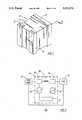
- FIG. 1is a perspective view of the monolythic surge suppressor of the present invention.
- FIG. 2is a circuit diagram of the surge suppressor in series with a power source and a load.
- FIG. 3is an enlarged perspective view similar to FIG. 1, but showing the surge suppressor in section as taken along line 3--3 of FIG. 1.
- substrate 30 and the conductive elements of the inventionare cross hatched, even though all surfaces along line 3--3 are in section.
- FIGS. 4-23are plan views of the printed layers in the assembly, showing the terminals in section.
- Surge suppressor 10comprises a laminated stack 12 having a first termination 14 printed over one end thereof, and having second and third terminations 16, 18 printed over the other end at the corners thereof.
- Terminations 14, 16, and 18are printed from ink comprised of a metal conductor, preferably silver. All three of the terminations 14, 16, and 18 are separate from one another and are not in electrical connection with one another.
- FIG. 2shows a circuit diagram wherein the surge suppressor 10 is incorporated in series between a power source 20 and a load 22.
- Load 22may comprise any electrical circuit which requires protection by the surge suppressor.
- the surge suppressorincludes a first varistor assembly 24, a second varistor assembly 26, and an inductance coil assembly 28. All of these assemblies are included in the laminated printed layers within laminated stack 12. Their connection to the three terminals 14, 16, and 18, are shown in FIG. 2.
- the varistors 24, 26act as insulators, and do not conduct current. Thus, current passes from the power source to first terminal 16, through inductance coil 28, and second terminal 18 to the load 22.
- the coil 28causes a build-up of voltage between the first terminal 16 and ground across the first varistor assembly 24.
- the varistor assembly 24reacts to this surge in voltage by becoming a conductor and permitting the shunting of the additional current to ground.
- the entire surgeis not shunted off by the first varistor 24, and under these conditions, a voltage drop occurs between second terminal 18 and ground through second varistor 26. This voltage drop causes the second varistor 26 to begin conducting current so as to shunt the remainder of the surge to ground.
- the first varistor 24 and the second varistor 26thus combine to protect the circuit load 22 from surges which might occur in the power source.
- the inductor coil 28 and the two varistor assemblies 24, 26were mounted on a circuit board as separate components.
- the present inventionincorporates these into the laminated monolythic surge suppressor 10 shown in FIGS. 1 and 3.
- FIGS. 4-7show the separate printed layers which make up the varistor assembly 24.
- the numeral 30designates an insulating wafer which can be constructed of any of a variety of materials such as alumina. Alternatively, it could be replaced with a green tape substrate commonly used in the industry.
- Printed over insulative layer 30is a bottom conductor sheet 32, preferrably comprised of silver.
- Bottom conductive sheet 32is spaced inwardly on three of its sides from the outer margins of the insulative layer 30, but its rear connector edge 33 coincides with the rear edge of the insulative layer 30 so that it is in electrical contact with first termination 14.
- Printed over conductive sheet 32is a varistor sheet 34.
- Varistor sheet 34completely covers conductive sheet 32 and extends to the outer margins of insulative layer 30.
- the varistor sheet 34is a varistor material preferably comprised of zinc oxide and containing semi-conductors.
- the preferred material for the varistor materialis a product manufactured by Raychem Corporation having an address of 300 Constitution Drive, Menlo Park, Calif.
- Printed over varistor sheet 34is a top conductor sheet 36 having a connector tab 38 which extends into electrical contact with the second termination or terminal 16. The remainder of conductive sheet 36 is spaced inwardly from the margins of insulative layer 30, and is spaced from and out of electrical contact with the terminals 14, 18. While the terminals 14, 16, 18 are shown in FIGS. 4-23, in the normal manufacturing process, the terminals are added after the various layers are printed. The terminals are shown in FIGS. 4-23 in order to show the inter-relationships between the various laminated layers and the terminals 14, 16, and 18.
- the layers 32, 34, 36may be repeated several times in order to achieve the desired characteristics for varistor 24. Referring to FIG. 3, these layers are shown repeated several times with the varistor layers 34 being sandwiched alternatively between the conductive layers 32, 36.
- the number of layerscan be increased or decreased to affect the electrical properties of the varistor 24. By increasing the number of layers, the plate area, and thus the current carrying capability of the varistor 24 will be increased.
- a ferrite layer 40is printed over the top of varistor 24.
- a first coil segment 42is printed over ferrite sheet 40.
- Coil 42includes an input end 44 which is in electrical contact with the second termination 16 and which includes an output end 46.
- Printed over first coil segment 42is a ferrite sheet 48 having a via way 50 therein which is positioned in registered alignment over the output end 46 of first coil segment 42.
- a via filler conductor 52is printed over the via opening 50 and fills the opening so as to form electrical connection with the outlet end 46 of first coil segment 42.
- FIG. 12illustrates a second coil segment 54 which is printed over ferrite layer 48 and which includes an input end 56 registered with an electrical contact with the filler conductor 52 so as to provide electrical continuity with the output end 46 of first coil segment 42.
- Second coil segment 54includes an output end 58.
- Another ferrite layer 60is printed over the second coil segment 54 and includes a via opening 62 registered above the outlet end 58 of second coil segment 54.
- a via filler conductor 64is printed over via opening 62 and fills the opening to provide electrical continuity with the output end 58 of second coil conductor 54.
- Printed over the ferrite layer 60is a third coil segment 66 which includes an input end 68 registered with and in an electrical contact with the via filler conductor 64.
- Third coil segment 66also includes an output end 70.
- Another ferrite layer 72is printed over third coil segment 66 and includes a via opening 74 registered with the output end 70 of third coil conductor 66.
- a via filler conductor 76is printed within via opening 74.
- Printed over the via filler conductor 76is a conductor plate 78 which extends into electrical contact with the third termination 18.
- electrical continuityis provided from second termination 16 (FIG. 9) through the three coil segments 42, 54, 66 in a clockwise fashion to the third termination 18 (FIG. 18).
- This arrangementis also shown schematically in FIG. 2 wherein the inductor coil 28 is connected in series between second termination 16 and third termination 18.
- FIGS. 19 through 22show the layers which are printed to construct the second varistor 26. These layers are also shown in FIG. 3.
- the initial layeris an insulative layer 80 which may be comprised of ferrite, or other insulative material.
- Printed over insulative layer 80is a bottom conductor sheet 82 which is spaced inwardly from three of the margins of the insulative layer 80, but which includes a connector edge 84 which is in electrical contact with the first termination 14.
- Printed over bottom conductor sheet 82is a varistor layer 86, and printed over the varistor layer 86 is a top conductive sheet 88 having a connector tab 90 which is in electrical contact with termination 18.
- an insulative layer 92is printed over the top.
- the terminations 14, 16, and 18are added after the entire laminated assembly has been printed. These terminations may be made of silver or other suitable conductors.
- FIGS. 4 through 23are printed by screen printing methods well known in the art.
- the thicknesses of each printare on the order of from 25 to 30 microns in thickness. In some cases, several layers of thick film prints are required to build up the desired thickness. This is particularly true with respect to the prints of varistor material 34 (FIG. 6) and 86 in FIG. 21.
- the number of layers printed and hence the material thicknesscan be varied to control the threshold voltage at which the varistor begins to conduct.
- the ferrite layers 40, 48, 60, and 72also each require more than a single print in order to prevent shorting between the conductors on their opposite faces. Several printings of each layer should be made in order to prevent the shorting between the conductors. Similarly, the insulative layer 80 and insulative layer 92 should each be comprised of several prints.
- the various conductive materials in the laminationhowever generally require only a single printing. This is true for the conductive sheets 32, 36 shown in FIGS. 5 and 7, the conductive coils 42, 54, 66, the conductive fillers 52, 64, 76, and the conductive plate 78. Similarly, the conductive sheets 82, 88 will require only a single printing.
- the number of repeated layers shown in FIG. 3is believed to be nearly the minimum number of layers necessary for a three component device.
- the number of layerscan be increased to affect the electrical properties of the varistors 24, 26 and the inductor 28. Repeating the layers 32, 34, 36 or 82, 86, 88 increases the corresponding plate area of the varistors 24, 26 respectively, and thus increases the current carrying capability of these varistors.
- inductance coil segments 42, 54, 66may be repeated as many as desired in order to achieve the inductance value of the component.
- the connector plate 78(FIG. 18) is large enough to cover either the filler conductor 64 (FIG. 14) or the filler conductor 76 (FIG. 17). This permits flexibility in the number of coil segments 42, 54, 66 which are included in the inductance coil. The number of coils can stop with either coil segment 54 or with coil segment 66 depending upon the desired inductance value required. In either case, the connector plate 78 will make contact with the output end of the final coil.
- solder terminations 14, 16, and 18are printed as shown in FIG. 1.
- the entire structure of the surge suppressor 10is still in its green state and must be fired before completion.
- the present inventionresults in a single part. However, efficiencies in manufacture can be improved by simultaneously printing of hundreds or even thousands of parts into a wafer. The resulting wafer after being fired can then be diced into individual parts with the solder terminations 14, 16, and 18 being applied after the dicing.
- the preferred embodiment of the present inventionincludes a single inductor 28 and two varistors 24, 26. These three components are connected in a "PI" arrangement.
- the varistor 24represents a first line of defense against a surge eminating from power source 20. It will remove a major portion of a voltage surge by clamping that voltage at the varistors clamping voltage level. However, because of the impedence characteristics of the varistor, it generally will not remove all of the surge. The remaining portion of the voltage surge will be conducted through inductor 28 to varistor 26.
- the inventioncan be simplified if desired by changing the device to a two component device including a single varistor and a single inductance coil.
- the terminations 14, 16, and 18provide flexibility for the component and permit the component to be surface mounted on a circuit board.
Landscapes
- Engineering & Computer Science (AREA)
- Microelectronics & Electronic Packaging (AREA)
- Physics & Mathematics (AREA)
- Electromagnetism (AREA)
- Thermistors And Varistors (AREA)
Abstract
Description
Claims (15)
Priority Applications (1)
| Application Number | Priority Date | Filing Date | Title |
|---|---|---|---|
| US07/914,801US5321573A (en) | 1992-07-16 | 1992-07-16 | Monolythic surge suppressor |
Applications Claiming Priority (1)
| Application Number | Priority Date | Filing Date | Title |
|---|---|---|---|
| US07/914,801US5321573A (en) | 1992-07-16 | 1992-07-16 | Monolythic surge suppressor |
Publications (1)
| Publication Number | Publication Date |
|---|---|
| US5321573Atrue US5321573A (en) | 1994-06-14 |
Family
ID=25434785
Family Applications (1)
| Application Number | Title | Priority Date | Filing Date |
|---|---|---|---|
| US07/914,801Expired - Fee RelatedUS5321573A (en) | 1992-07-16 | 1992-07-16 | Monolythic surge suppressor |
Country Status (1)
| Country | Link |
|---|---|
| US (1) | US5321573A (en) |
Cited By (82)
| Publication number | Priority date | Publication date | Assignee | Title |
|---|---|---|---|---|
| EP0786927A1 (en)* | 1996-01-25 | 1997-07-30 | Murata Manufacturing Co., Ltd. | Composite functional device and method for producing the same |
| US5666277A (en)* | 1994-09-23 | 1997-09-09 | Asea Brown Boveri Ab | Series-compensated converter station |
| US5909350A (en)* | 1997-04-08 | 1999-06-01 | X2Y Attenuators, L.L.C. | Paired multi-layered dielectric independent passive component architecture resulting in differential and common mode filtering with surge protection in one integrated package |
| US6018448A (en)* | 1997-04-08 | 2000-01-25 | X2Y Attenuators, L.L.C. | Paired multi-layered dielectric independent passive component architecture resulting in differential and common mode filtering with surge protection in one integrated package |
| US6061223A (en)* | 1997-10-14 | 2000-05-09 | Polyphaser Corporation | Surge suppressor device |
| US6097581A (en)* | 1997-04-08 | 2000-08-01 | X2Y Attenuators, Llc | Paired multi-layered dielectric independent passive component architecture resulting in differential and common mode filtering with surge protection in one integrated package |
| US20010048581A1 (en)* | 1997-04-08 | 2001-12-06 | X2Y Attenuators, L.L.C. | Predetermined symmetrically balanced amalgam with complementary paired portions comprising shielding electrodes and shielded electrodes and other predetermined element portions for symmetrically balanced and complementary energy portion conditioning |
| US6373673B1 (en) | 1997-04-08 | 2002-04-16 | X2Y Attenuators, Llc | Multi-functional energy conditioner |
| US6498710B1 (en) | 1997-04-08 | 2002-12-24 | X2Y Attenuators, Llc | Paired multi-layered dielectric independent passive component architecture resulting in differential and common mode filtering with surge protection in one integrated package |
| US6509807B1 (en)* | 1997-04-08 | 2003-01-21 | X2Y Attenuators, Llc | Energy conditioning circuit assembly |
| US20030072121A1 (en)* | 2001-10-12 | 2003-04-17 | Polyphaser Corporation | Rf surge protection device |
| DE10201438A1 (en)* | 2002-01-16 | 2003-07-24 | Epcos Ag | Antenna switching circuit for mobile telephone has antenna input and control line of switching module coupled to respective electrostatic discharge protection devices |
| US6603646B2 (en) | 1997-04-08 | 2003-08-05 | X2Y Attenuators, Llc | Multi-functional energy conditioner |
| US6606011B2 (en) | 1998-04-07 | 2003-08-12 | X2Y Attenuators, Llc | Energy conditioning circuit assembly |
| US20030161086A1 (en)* | 2000-07-18 | 2003-08-28 | X2Y Attenuators, Llc | Paired multi-layered dielectric independent passive component architecture resulting in differential and common mode filtering with surge protection in one integrated package |
| US20030179533A1 (en)* | 2002-03-21 | 2003-09-25 | Polyphaser Corporation | Isolated shield coaxial surge suppressor |
| US6636406B1 (en) | 1997-04-08 | 2003-10-21 | X2Y Attenuators, Llc | Universal multi-functional common conductive shield structure for electrical circuitry and energy conditioning |
| US6650525B2 (en) | 1997-04-08 | 2003-11-18 | X2Y Attenuators, Llc | Component carrier |
| US6687108B1 (en) | 1997-04-08 | 2004-02-03 | X2Y Attenuators, Llc | Passive electrostatic shielding structure for electrical circuitry and energy conditioning with outer partial shielded energy pathways |
| DE10201434A1 (en)* | 2002-01-16 | 2004-03-04 | Epcos Ag | Antenna switching circuit for mobile telephone has antenna input coupled to electrostatic discharge protection device |
| US6738249B1 (en) | 1997-04-08 | 2004-05-18 | X2Y Attenuators, Llc | Universal energy conditioning interposer with circuit architecture |
| US20040130388A1 (en)* | 2001-01-18 | 2004-07-08 | Christian Block | Electric circuit module, circuit module arrangement and use of said circuit module and of said circuit module arrangement |
| US20040257740A1 (en)* | 2001-09-28 | 2004-12-23 | Christian Block | Circuit arrangement, switching module comprising said circuit arrangement and use of switching module |
| US20040264095A1 (en)* | 2001-09-28 | 2004-12-30 | Christian Block | Circuit arrangement, switching module comprising said circuit arrangement and use of said switching module |
| US6846693B2 (en)* | 1999-10-19 | 2005-01-25 | Murata Manufacturing Co., Ltd. | Chip-type composite electronic component and manufacturing method thereof |
| US20050059358A1 (en)* | 2001-09-28 | 2005-03-17 | Christian Block | Circuit, switching module comprising the same, and use of said switching module |
| US20050059371A1 (en)* | 2001-09-28 | 2005-03-17 | Christian Block | Circuit arrangement, switching module comprising said circuit arrangement and use of switching module |
| US20050078426A1 (en)* | 2003-08-22 | 2005-04-14 | Keio University | System using power converter, microsurge suppressor and microsurge suppression method |
| US6894884B2 (en) | 1997-04-08 | 2005-05-17 | Xzy Attenuators, Llc | Offset pathway arrangements for energy conditioning |
| US6954346B2 (en) | 1997-04-08 | 2005-10-11 | Xzy Attenuators, Llc | Filter assembly |
| US6995983B1 (en) | 1997-04-08 | 2006-02-07 | X2Y Attenuators, Llc | Component carrier |
| US7042703B2 (en) | 2000-03-22 | 2006-05-09 | X2Y Attenuators, Llc | Energy conditioning structure |
| US7106570B2 (en) | 1997-04-08 | 2006-09-12 | Xzy Altenuators, Llc | Pathway arrangement |
| US7110227B2 (en) | 1997-04-08 | 2006-09-19 | X2Y Attenuators, Llc | Universial energy conditioning interposer with circuit architecture |
| US7110235B2 (en) | 1997-04-08 | 2006-09-19 | Xzy Altenuators, Llc | Arrangement for energy conditioning |
| US7113383B2 (en) | 2000-04-28 | 2006-09-26 | X2Y Attenuators, Llc | Predetermined symmetrically balanced amalgam with complementary paired portions comprising shielding electrodes and shielded electrodes and other predetermined element portions for symmetrically balanced and complementary energy portion conditioning |
| US7141899B2 (en) | 1998-04-07 | 2006-11-28 | X2Y Attenuators, Llc | Component carrier |
| US7180718B2 (en) | 2003-01-31 | 2007-02-20 | X2Y Attenuators, Llc | Shielded energy conditioner |
| US7193831B2 (en) | 2000-10-17 | 2007-03-20 | X2Y Attenuators, Llc | Energy pathway arrangement |
| US7224564B2 (en) | 2000-10-17 | 2007-05-29 | X2Y Attenuators, Llc | Amalgam of shielding and shielded energy pathways and other elements for single or multiple circuitries with common reference node |
| US7262949B2 (en) | 2000-08-15 | 2007-08-28 | X2Y Attenuators, Llc | Electrode arrangement for circuit energy conditioning |
| US7274549B2 (en) | 2000-12-15 | 2007-09-25 | X2Y Attenuators, Llc | Energy pathway arrangements for energy conditioning |
| US7301748B2 (en) | 1997-04-08 | 2007-11-27 | Anthony Anthony A | Universal energy conditioning interposer with circuit architecture |
| US7321485B2 (en) | 1997-04-08 | 2008-01-22 | X2Y Attenuators, Llc | Arrangement for energy conditioning |
| US7336467B2 (en) | 2000-10-17 | 2008-02-26 | X2Y Attenuators, Llc | Energy pathway arrangement |
| US7336468B2 (en) | 1997-04-08 | 2008-02-26 | X2Y Attenuators, Llc | Arrangement for energy conditioning |
| US7427816B2 (en) | 1998-04-07 | 2008-09-23 | X2Y Attenuators, Llc | Component carrier |
| US7440252B2 (en) | 2003-05-29 | 2008-10-21 | X2Y Attenuators, Llc | Connector related structures including an energy conditioner |
| US20090103226A1 (en)* | 2007-10-18 | 2009-04-23 | Polyphaser Corporation | Surge suppression device having one or more rings |
| US20090109584A1 (en)* | 2007-10-30 | 2009-04-30 | Polyphaser Corporation | Surge protection circuit for passing dc and rf signals |
| US7586728B2 (en) | 2005-03-14 | 2009-09-08 | X2Y Attenuators, Llc | Conditioner with coplanar conductors |
| US20090284888A1 (en)* | 2008-05-19 | 2009-11-19 | Polyphaser Corporation | Dc and rf pass broadband surge suppressor |
| US7630188B2 (en) | 2005-03-01 | 2009-12-08 | X2Y Attenuators, Llc | Conditioner with coplanar conductors |
| US7675729B2 (en) | 2003-12-22 | 2010-03-09 | X2Y Attenuators, Llc | Internally shielded energy conditioner |
| US7817397B2 (en) | 2005-03-01 | 2010-10-19 | X2Y Attenuators, Llc | Energy conditioner with tied through electrodes |
| US20110080683A1 (en)* | 2009-10-02 | 2011-04-07 | Jones Jonathan L | Rf coaxial surge protectors with non-linear protection devices |
| US20110159727A1 (en)* | 2009-12-28 | 2011-06-30 | Matt Howard | Power distribution device |
| US8026777B2 (en) | 2006-03-07 | 2011-09-27 | X2Y Attenuators, Llc | Energy conditioner structures |
| US20110235229A1 (en)* | 2010-03-26 | 2011-09-29 | Nguyen Eric H | Ethernet surge protector |
| US8116046B2 (en) | 2002-10-02 | 2012-02-14 | Epcos Ag | Circuit arrangement that includes a device to protect against electrostatic discharge |
| US20120099285A1 (en)* | 2010-10-02 | 2012-04-26 | Biar Jeff | Laminated substrate with coils |
| US8432693B2 (en) | 2010-05-04 | 2013-04-30 | Transtector Systems, Inc. | High power band pass RF filter having a gas tube for surge suppression |
| US8441795B2 (en) | 2010-05-04 | 2013-05-14 | Transtector Systems, Inc. | High power band pass RF filter having a gas tube for surge suppression |
| US8611062B2 (en) | 2010-05-13 | 2013-12-17 | Transtector Systems, Inc. | Surge current sensor and surge protection system including the same |
| US8730637B2 (en) | 2010-12-17 | 2014-05-20 | Transtector Systems, Inc. | Surge protection devices that fail as an open circuit |
| US8730640B2 (en) | 2010-05-11 | 2014-05-20 | Transtector Systems, Inc. | DC pass RF protector having a surge suppression module |
| US8976500B2 (en) | 2010-05-26 | 2015-03-10 | Transtector Systems, Inc. | DC block RF coaxial devices |
| US9048662B2 (en) | 2012-03-19 | 2015-06-02 | Transtector Systems, Inc. | DC power surge protector |
| US9054094B2 (en) | 1997-04-08 | 2015-06-09 | X2Y Attenuators, Llc | Energy conditioning circuit arrangement for integrated circuit |
| US9054514B2 (en) | 2012-02-10 | 2015-06-09 | Transtector Systems, Inc. | Reduced let through voltage transient protection or suppression circuit |
| US20150213956A1 (en)* | 2014-01-27 | 2015-07-30 | Samsung Electro-Mechanics Co., Ltd. | Multilayer ceramic capacitor and board with the same mounted thereon |
| US9124093B2 (en) | 2012-09-21 | 2015-09-01 | Transtector Systems, Inc. | Rail surge voltage protector with fail disconnect |
| US9190837B2 (en) | 2012-05-03 | 2015-11-17 | Transtector Systems, Inc. | Rigid flex electromagnetic pulse protection device |
| US9924609B2 (en) | 2015-07-24 | 2018-03-20 | Transtector Systems, Inc. | Modular protection cabinet with flexible backplane |
| US9991697B1 (en) | 2016-12-06 | 2018-06-05 | Transtector Systems, Inc. | Fail open or fail short surge protector |
| US10129993B2 (en) | 2015-06-09 | 2018-11-13 | Transtector Systems, Inc. | Sealed enclosure for protecting electronics |
| US10193335B2 (en) | 2015-10-27 | 2019-01-29 | Transtector Systems, Inc. | Radio frequency surge protector with matched piston-cylinder cavity shape |
| US10356928B2 (en) | 2015-07-24 | 2019-07-16 | Transtector Systems, Inc. | Modular protection cabinet with flexible backplane |
| US10588236B2 (en) | 2015-07-24 | 2020-03-10 | Transtector Systems, Inc. | Modular protection cabinet with flexible backplane |
| US11009574B2 (en)* | 2018-07-25 | 2021-05-18 | Murata Manufacturing Co., Ltd. | Coil array component |
| US11694834B2 (en) | 2018-07-25 | 2023-07-04 | Murata Manufacturing Co., Ltd. | Coil array component |
| US11784502B2 (en) | 2014-03-04 | 2023-10-10 | Scramoge Technology Limited | Wireless charging and communication board and wireless charging and communication device |
Citations (2)
| Publication number | Priority date | Publication date | Assignee | Title |
|---|---|---|---|---|
| US4658153A (en)* | 1984-06-18 | 1987-04-14 | Amnon Brosh | Planar coil apparatus for providing a frequency output vs. position |
| US5142430A (en)* | 1990-03-28 | 1992-08-25 | Anthony Anthony A | Power line filter and surge protection circuit components and circuits |
- 1992
- 1992-07-16USUS07/914,801patent/US5321573A/ennot_activeExpired - Fee Related
Patent Citations (2)
| Publication number | Priority date | Publication date | Assignee | Title |
|---|---|---|---|---|
| US4658153A (en)* | 1984-06-18 | 1987-04-14 | Amnon Brosh | Planar coil apparatus for providing a frequency output vs. position |
| US5142430A (en)* | 1990-03-28 | 1992-08-25 | Anthony Anthony A | Power line filter and surge protection circuit components and circuits |
Cited By (131)
| Publication number | Priority date | Publication date | Assignee | Title |
|---|---|---|---|---|
| US5666277A (en)* | 1994-09-23 | 1997-09-09 | Asea Brown Boveri Ab | Series-compensated converter station |
| EP0786927A1 (en)* | 1996-01-25 | 1997-07-30 | Murata Manufacturing Co., Ltd. | Composite functional device and method for producing the same |
| US6873513B2 (en) | 1997-04-08 | 2005-03-29 | X2Y Attenuators, Llc | Paired multi-layered dielectric independent passive component architecture resulting in differential and common mode filtering with surge protection in one integrated package |
| US6738249B1 (en) | 1997-04-08 | 2004-05-18 | X2Y Attenuators, Llc | Universal energy conditioning interposer with circuit architecture |
| US7609500B2 (en) | 1997-04-08 | 2009-10-27 | X2Y Attenuators, Llc | Universal energy conditioning interposer with circuit architecture |
| US6097581A (en)* | 1997-04-08 | 2000-08-01 | X2Y Attenuators, Llc | Paired multi-layered dielectric independent passive component architecture resulting in differential and common mode filtering with surge protection in one integrated package |
| US7321485B2 (en) | 1997-04-08 | 2008-01-22 | X2Y Attenuators, Llc | Arrangement for energy conditioning |
| US7916444B2 (en) | 1997-04-08 | 2011-03-29 | X2Y Attenuators, Llc | Arrangement for energy conditioning |
| US20010048581A1 (en)* | 1997-04-08 | 2001-12-06 | X2Y Attenuators, L.L.C. | Predetermined symmetrically balanced amalgam with complementary paired portions comprising shielding electrodes and shielded electrodes and other predetermined element portions for symmetrically balanced and complementary energy portion conditioning |
| US6331926B1 (en) | 1997-04-08 | 2001-12-18 | Anthony A. Anthony | Paired multi-layered dielectric independent passive component architecture resulting in differential and common mode filtering with surge protection in one integrated package |
| US6373673B1 (en) | 1997-04-08 | 2002-04-16 | X2Y Attenuators, Llc | Multi-functional energy conditioner |
| US6498710B1 (en) | 1997-04-08 | 2002-12-24 | X2Y Attenuators, Llc | Paired multi-layered dielectric independent passive component architecture resulting in differential and common mode filtering with surge protection in one integrated package |
| US6509807B1 (en)* | 1997-04-08 | 2003-01-21 | X2Y Attenuators, Llc | Energy conditioning circuit assembly |
| US9373592B2 (en) | 1997-04-08 | 2016-06-21 | X2Y Attenuators, Llc | Arrangement for energy conditioning |
| US6580595B2 (en) | 1997-04-08 | 2003-06-17 | X2Y Attenuators, Llc | Predetermined symmetrically balanced amalgam with complementary paired portions comprising shielding electrodes and shielded electrodes and other predetermined element portions for symmetrically balanced and complementary energy portion conditioning |
| US6594128B2 (en) | 1997-04-08 | 2003-07-15 | X2Y Attenuators, Llc | Paired multi-layered dielectric independent passive component architecture resulting in differential and common mode filtering with surge protection in one integrated package |
| US9054094B2 (en) | 1997-04-08 | 2015-06-09 | X2Y Attenuators, Llc | Energy conditioning circuit arrangement for integrated circuit |
| US6603646B2 (en) | 1997-04-08 | 2003-08-05 | X2Y Attenuators, Llc | Multi-functional energy conditioner |
| US6018448A (en)* | 1997-04-08 | 2000-01-25 | X2Y Attenuators, L.L.C. | Paired multi-layered dielectric independent passive component architecture resulting in differential and common mode filtering with surge protection in one integrated package |
| US7609501B2 (en) | 1997-04-08 | 2009-10-27 | X2Y Attenuators, Llc | Manufacture including shield structure |
| US9036319B2 (en) | 1997-04-08 | 2015-05-19 | X2Y Attenuators, Llc | Arrangement for energy conditioning |
| US6636406B1 (en) | 1997-04-08 | 2003-10-21 | X2Y Attenuators, Llc | Universal multi-functional common conductive shield structure for electrical circuitry and energy conditioning |
| US6650525B2 (en) | 1997-04-08 | 2003-11-18 | X2Y Attenuators, Llc | Component carrier |
| US20030231451A1 (en)* | 1997-04-08 | 2003-12-18 | Anthony Anthony A. | Component carrier |
| US6687108B1 (en) | 1997-04-08 | 2004-02-03 | X2Y Attenuators, Llc | Passive electrostatic shielding structure for electrical circuitry and energy conditioning with outer partial shielded energy pathways |
| US20040027771A1 (en)* | 1997-04-08 | 2004-02-12 | Anthony Anthony A. | Paired multi-layered dielectric independent passive component architecture resulting in differential and common mode filtering with surge protection in one integrated package |
| US9019679B2 (en) | 1997-04-08 | 2015-04-28 | X2Y Attenuators, Llc | Arrangement for energy conditioning |
| US7301748B2 (en) | 1997-04-08 | 2007-11-27 | Anthony Anthony A | Universal energy conditioning interposer with circuit architecture |
| US7443647B2 (en) | 1997-04-08 | 2008-10-28 | X2Y Attenuators, Llc | Paired multi-layered dielectric independent passive component architecture resulting in differential and common mode filtering with surge protection in one integrated package |
| US8587915B2 (en) | 1997-04-08 | 2013-11-19 | X2Y Attenuators, Llc | Arrangement for energy conditioning |
| US8023241B2 (en) | 1997-04-08 | 2011-09-20 | X2Y Attenuators, Llc | Arrangement for energy conditioning |
| US5909350A (en)* | 1997-04-08 | 1999-06-01 | X2Y Attenuators, L.L.C. | Paired multi-layered dielectric independent passive component architecture resulting in differential and common mode filtering with surge protection in one integrated package |
| US7688565B2 (en) | 1997-04-08 | 2010-03-30 | X2Y Attenuators, Llc | Arrangements for energy conditioning |
| US8018706B2 (en) | 1997-04-08 | 2011-09-13 | X2Y Attenuators, Llc | Arrangement for energy conditioning |
| US7336468B2 (en) | 1997-04-08 | 2008-02-26 | X2Y Attenuators, Llc | Arrangement for energy conditioning |
| US8004812B2 (en) | 1997-04-08 | 2011-08-23 | X2Y Attenuators, Llc | Energy conditioning circuit arrangement for integrated circuit |
| US7050284B2 (en) | 1997-04-08 | 2006-05-23 | X2Y Attenuators, Llc | Component carrier |
| US6894884B2 (en) | 1997-04-08 | 2005-05-17 | Xzy Attenuators, Llc | Offset pathway arrangements for energy conditioning |
| US6954346B2 (en) | 1997-04-08 | 2005-10-11 | Xzy Attenuators, Llc | Filter assembly |
| US7920367B2 (en) | 1997-04-08 | 2011-04-05 | X2Y Attenuators, Llc | Method for making arrangement for energy conditioning |
| US6995983B1 (en) | 1997-04-08 | 2006-02-07 | X2Y Attenuators, Llc | Component carrier |
| US7423860B2 (en) | 1997-04-08 | 2008-09-09 | X2Y Attenuators, Llc | Multi-functional energy conditioner |
| US7733621B2 (en) | 1997-04-08 | 2010-06-08 | X2Y Attenuators, Llc | Energy conditioning circuit arrangement for integrated circuit |
| US7593208B2 (en) | 1997-04-08 | 2009-09-22 | X2Y Attenuators, Llc | Multi-functional energy conditioner |
| US7106570B2 (en) | 1997-04-08 | 2006-09-12 | Xzy Altenuators, Llc | Pathway arrangement |
| US7110227B2 (en) | 1997-04-08 | 2006-09-19 | X2Y Attenuators, Llc | Universial energy conditioning interposer with circuit architecture |
| US7110235B2 (en) | 1997-04-08 | 2006-09-19 | Xzy Altenuators, Llc | Arrangement for energy conditioning |
| US7768763B2 (en) | 1997-04-08 | 2010-08-03 | X2Y Attenuators, Llc | Arrangement for energy conditioning |
| US6061223A (en)* | 1997-10-14 | 2000-05-09 | Polyphaser Corporation | Surge suppressor device |
| US6236551B1 (en) | 1997-10-14 | 2001-05-22 | Polyphaser Corporation | Surge suppressor device |
| US6115227A (en)* | 1997-10-14 | 2000-09-05 | Polyphaser Corporation | Surge suppressor device |
| US6606011B2 (en) | 1998-04-07 | 2003-08-12 | X2Y Attenuators, Llc | Energy conditioning circuit assembly |
| US7141899B2 (en) | 1998-04-07 | 2006-11-28 | X2Y Attenuators, Llc | Component carrier |
| US7427816B2 (en) | 1998-04-07 | 2008-09-23 | X2Y Attenuators, Llc | Component carrier |
| US7042303B2 (en) | 1998-04-07 | 2006-05-09 | X2Y Attenuators, Llc | Energy conditioning circuit assembly |
| US6846693B2 (en)* | 1999-10-19 | 2005-01-25 | Murata Manufacturing Co., Ltd. | Chip-type composite electronic component and manufacturing method thereof |
| US7042703B2 (en) | 2000-03-22 | 2006-05-09 | X2Y Attenuators, Llc | Energy conditioning structure |
| US7113383B2 (en) | 2000-04-28 | 2006-09-26 | X2Y Attenuators, Llc | Predetermined symmetrically balanced amalgam with complementary paired portions comprising shielding electrodes and shielded electrodes and other predetermined element portions for symmetrically balanced and complementary energy portion conditioning |
| US20030161086A1 (en)* | 2000-07-18 | 2003-08-28 | X2Y Attenuators, Llc | Paired multi-layered dielectric independent passive component architecture resulting in differential and common mode filtering with surge protection in one integrated package |
| US7262949B2 (en) | 2000-08-15 | 2007-08-28 | X2Y Attenuators, Llc | Electrode arrangement for circuit energy conditioning |
| US7336467B2 (en) | 2000-10-17 | 2008-02-26 | X2Y Attenuators, Llc | Energy pathway arrangement |
| US7193831B2 (en) | 2000-10-17 | 2007-03-20 | X2Y Attenuators, Llc | Energy pathway arrangement |
| US7224564B2 (en) | 2000-10-17 | 2007-05-29 | X2Y Attenuators, Llc | Amalgam of shielding and shielded energy pathways and other elements for single or multiple circuitries with common reference node |
| US7428134B2 (en) | 2000-10-17 | 2008-09-23 | X2Y Attenuators, Llc | Energy pathway arrangements for energy conditioning |
| US7433168B2 (en) | 2000-10-17 | 2008-10-07 | X2Y Attenuators, Llc | Amalgam of shielding and shielded energy pathways and other elements for single or multiple circuitries with common reference node |
| US7274549B2 (en) | 2000-12-15 | 2007-09-25 | X2Y Attenuators, Llc | Energy pathway arrangements for energy conditioning |
| US20040130388A1 (en)* | 2001-01-18 | 2004-07-08 | Christian Block | Electric circuit module, circuit module arrangement and use of said circuit module and of said circuit module arrangement |
| US8014731B2 (en) | 2001-01-18 | 2011-09-06 | Epcos Ag | Electric circuit module, circuit module arrangement and use of said circuit module and of said circuit module arrangement |
| US20040264095A1 (en)* | 2001-09-28 | 2004-12-30 | Christian Block | Circuit arrangement, switching module comprising said circuit arrangement and use of said switching module |
| US7492565B2 (en) | 2001-09-28 | 2009-02-17 | Epcos Ag | Bandpass filter electrostatic discharge protection device |
| US20040257740A1 (en)* | 2001-09-28 | 2004-12-23 | Christian Block | Circuit arrangement, switching module comprising said circuit arrangement and use of switching module |
| US20050059358A1 (en)* | 2001-09-28 | 2005-03-17 | Christian Block | Circuit, switching module comprising the same, and use of said switching module |
| US20050059371A1 (en)* | 2001-09-28 | 2005-03-17 | Christian Block | Circuit arrangement, switching module comprising said circuit arrangement and use of switching module |
| US7343137B2 (en) | 2001-09-28 | 2008-03-11 | Epcos Ag | Circuit, switching module comprising the same, and use of said switching module |
| US20030072121A1 (en)* | 2001-10-12 | 2003-04-17 | Polyphaser Corporation | Rf surge protection device |
| US6785110B2 (en) | 2001-10-12 | 2004-08-31 | Polyphaser Corporation | Rf surge protection device |
| DE10201434A1 (en)* | 2002-01-16 | 2004-03-04 | Epcos Ag | Antenna switching circuit for mobile telephone has antenna input coupled to electrostatic discharge protection device |
| DE10201438A1 (en)* | 2002-01-16 | 2003-07-24 | Epcos Ag | Antenna switching circuit for mobile telephone has antenna input and control line of switching module coupled to respective electrostatic discharge protection devices |
| US20030179533A1 (en)* | 2002-03-21 | 2003-09-25 | Polyphaser Corporation | Isolated shield coaxial surge suppressor |
| US6975496B2 (en) | 2002-03-21 | 2005-12-13 | Polyphaser Corporation | Isolated shield coaxial surge suppressor |
| US8116046B2 (en) | 2002-10-02 | 2012-02-14 | Epcos Ag | Circuit arrangement that includes a device to protect against electrostatic discharge |
| US7180718B2 (en) | 2003-01-31 | 2007-02-20 | X2Y Attenuators, Llc | Shielded energy conditioner |
| US7440252B2 (en) | 2003-05-29 | 2008-10-21 | X2Y Attenuators, Llc | Connector related structures including an energy conditioner |
| US20050078426A1 (en)* | 2003-08-22 | 2005-04-14 | Keio University | System using power converter, microsurge suppressor and microsurge suppression method |
| US7342799B2 (en)* | 2003-08-22 | 2008-03-11 | Keio University | System using power converter, microsurge suppressor and microsurge suppression method |
| US7675729B2 (en) | 2003-12-22 | 2010-03-09 | X2Y Attenuators, Llc | Internally shielded energy conditioner |
| US8547677B2 (en) | 2005-03-01 | 2013-10-01 | X2Y Attenuators, Llc | Method for making internally overlapped conditioners |
| US7974062B2 (en) | 2005-03-01 | 2011-07-05 | X2Y Attenuators, Llc | Internally overlapped conditioners |
| US9001486B2 (en) | 2005-03-01 | 2015-04-07 | X2Y Attenuators, Llc | Internally overlapped conditioners |
| US8014119B2 (en) | 2005-03-01 | 2011-09-06 | X2Y Attenuators, Llc | Energy conditioner with tied through electrodes |
| US7782587B2 (en) | 2005-03-01 | 2010-08-24 | X2Y Attenuators, Llc | Internally overlapped conditioners |
| US7630188B2 (en) | 2005-03-01 | 2009-12-08 | X2Y Attenuators, Llc | Conditioner with coplanar conductors |
| US7817397B2 (en) | 2005-03-01 | 2010-10-19 | X2Y Attenuators, Llc | Energy conditioner with tied through electrodes |
| US7586728B2 (en) | 2005-03-14 | 2009-09-08 | X2Y Attenuators, Llc | Conditioner with coplanar conductors |
| US8026777B2 (en) | 2006-03-07 | 2011-09-27 | X2Y Attenuators, Llc | Energy conditioner structures |
| US8027136B2 (en) | 2007-10-18 | 2011-09-27 | Transtector Systems, Inc. | Surge suppression device having one or more rings |
| US20090103226A1 (en)* | 2007-10-18 | 2009-04-23 | Polyphaser Corporation | Surge suppression device having one or more rings |
| US8553386B2 (en) | 2007-10-18 | 2013-10-08 | Transtector Systems, Inc. | Surge suppression device having one or more rings |
| US20110141646A1 (en)* | 2007-10-30 | 2011-06-16 | Jones Jonathan L | Surge protection circuit for passing dc and rf signals |
| US20090109584A1 (en)* | 2007-10-30 | 2009-04-30 | Polyphaser Corporation | Surge protection circuit for passing dc and rf signals |
| US7944670B2 (en) | 2007-10-30 | 2011-05-17 | Transtector Systems, Inc. | Surge protection circuit for passing DC and RF signals |
| US8179656B2 (en) | 2007-10-30 | 2012-05-15 | Transtector Systems, Inc. | Surge protection circuit for passing DC and RF signals |
| US20090284888A1 (en)* | 2008-05-19 | 2009-11-19 | Polyphaser Corporation | Dc and rf pass broadband surge suppressor |
| US8599528B2 (en) | 2008-05-19 | 2013-12-03 | Transtector Systems, Inc. | DC and RF pass broadband surge suppressor |
| US8456791B2 (en) | 2009-10-02 | 2013-06-04 | Transtector Systems, Inc. | RF coaxial surge protectors with non-linear protection devices |
| US20110080683A1 (en)* | 2009-10-02 | 2011-04-07 | Jones Jonathan L | Rf coaxial surge protectors with non-linear protection devices |
| US8400760B2 (en) | 2009-12-28 | 2013-03-19 | Transtector Systems, Inc. | Power distribution device |
| US20110159727A1 (en)* | 2009-12-28 | 2011-06-30 | Matt Howard | Power distribution device |
| US20110235229A1 (en)* | 2010-03-26 | 2011-09-29 | Nguyen Eric H | Ethernet surge protector |
| US8441795B2 (en) | 2010-05-04 | 2013-05-14 | Transtector Systems, Inc. | High power band pass RF filter having a gas tube for surge suppression |
| US8432693B2 (en) | 2010-05-04 | 2013-04-30 | Transtector Systems, Inc. | High power band pass RF filter having a gas tube for surge suppression |
| US8730640B2 (en) | 2010-05-11 | 2014-05-20 | Transtector Systems, Inc. | DC pass RF protector having a surge suppression module |
| US8611062B2 (en) | 2010-05-13 | 2013-12-17 | Transtector Systems, Inc. | Surge current sensor and surge protection system including the same |
| US8976500B2 (en) | 2010-05-26 | 2015-03-10 | Transtector Systems, Inc. | DC block RF coaxial devices |
| US20120099285A1 (en)* | 2010-10-02 | 2012-04-26 | Biar Jeff | Laminated substrate with coils |
| US8730637B2 (en) | 2010-12-17 | 2014-05-20 | Transtector Systems, Inc. | Surge protection devices that fail as an open circuit |
| US9054514B2 (en) | 2012-02-10 | 2015-06-09 | Transtector Systems, Inc. | Reduced let through voltage transient protection or suppression circuit |
| US9048662B2 (en) | 2012-03-19 | 2015-06-02 | Transtector Systems, Inc. | DC power surge protector |
| US9190837B2 (en) | 2012-05-03 | 2015-11-17 | Transtector Systems, Inc. | Rigid flex electromagnetic pulse protection device |
| US9124093B2 (en) | 2012-09-21 | 2015-09-01 | Transtector Systems, Inc. | Rail surge voltage protector with fail disconnect |
| US9390859B2 (en)* | 2014-01-27 | 2016-07-12 | Samsung Electro-Mechanics Co., Ltd. | Multilayer ceramic capacitor and board with the same mounted thereon |
| US20150213956A1 (en)* | 2014-01-27 | 2015-07-30 | Samsung Electro-Mechanics Co., Ltd. | Multilayer ceramic capacitor and board with the same mounted thereon |
| US11784502B2 (en) | 2014-03-04 | 2023-10-10 | Scramoge Technology Limited | Wireless charging and communication board and wireless charging and communication device |
| US10129993B2 (en) | 2015-06-09 | 2018-11-13 | Transtector Systems, Inc. | Sealed enclosure for protecting electronics |
| US9924609B2 (en) | 2015-07-24 | 2018-03-20 | Transtector Systems, Inc. | Modular protection cabinet with flexible backplane |
| US10356928B2 (en) | 2015-07-24 | 2019-07-16 | Transtector Systems, Inc. | Modular protection cabinet with flexible backplane |
| US10588236B2 (en) | 2015-07-24 | 2020-03-10 | Transtector Systems, Inc. | Modular protection cabinet with flexible backplane |
| US10193335B2 (en) | 2015-10-27 | 2019-01-29 | Transtector Systems, Inc. | Radio frequency surge protector with matched piston-cylinder cavity shape |
| US9991697B1 (en) | 2016-12-06 | 2018-06-05 | Transtector Systems, Inc. | Fail open or fail short surge protector |
| US11009574B2 (en)* | 2018-07-25 | 2021-05-18 | Murata Manufacturing Co., Ltd. | Coil array component |
| US11694834B2 (en) | 2018-07-25 | 2023-07-04 | Murata Manufacturing Co., Ltd. | Coil array component |
Similar Documents
| Publication | Publication Date | Title |
|---|---|---|
| US5321573A (en) | Monolythic surge suppressor | |
| EP1516404B1 (en) | Integrated device providing overcurrent and overvoltage protection and common-mode filtering to data bus interface | |
| EP0523190B1 (en) | Power line filter and surge protection circuit components and circuits | |
| KR100712058B1 (en) | Electrostatic countermeasure parts | |
| US6223423B1 (en) | Multilayer conductive polymer positive temperature coefficient device | |
| US6236302B1 (en) | Multilayer conductive polymer device and method of manufacturing same | |
| GB2195828A (en) | Fused ceramic capacitor | |
| CN1045505C (en) | Protective devices for surge current protection of associated equipment in communication systems | |
| US10181718B2 (en) | Surface-mountable electrical circuit protection device | |
| JPH04257112A (en) | Laminated chip t-type filter | |
| KR100638802B1 (en) | Multilayer Chip Device with Various Capacitance Values | |
| JP2023113814A (en) | low aspect ratio varistor | |
| JPH04277601A (en) | Varistor component | |
| JP2932768B2 (en) | Chip varistor with resistor | |
| JP3232713B2 (en) | Noise filter | |
| KR100502281B1 (en) | Complex array chip of combining with various devices and fabricating method therefor | |
| KR100246730B1 (en) | Chip barristor and its setting apparatus | |
| JPS61102006A (en) | surge absorber | |
| HK40026710A (en) | Low aspect ratio varistor | |
| HK40026710B (en) | Low aspect ratio varistor | |
| JP3182844B2 (en) | Noise filter | |
| CN114172115A (en) | A Circuit Protection Component Based on Laminate Technology | |
| JPH0529109A (en) | Varistor part | |
| KR20170010722A (en) | Electric shock protection device and mobile electronic device with the same | |
| JP2005303223A (en) | Multilayer ceramic chip varistor |
Legal Events
| Date | Code | Title | Description |
|---|---|---|---|
| AS | Assignment | Owner name:DALE ELECTRONICS, INC., NEBRASKA Free format text:ASSIGNMENT OF ASSIGNORS INTEREST.;ASSIGNORS:PERSON, HERMAN R.;VEIK, THOMAS L.;REEL/FRAME:006209/0401 Effective date:19920709 | |
| FPAY | Fee payment | Year of fee payment:4 | |
| AS | Assignment | Owner name:VISHAY DALE ELECTRONICS, INC., NEBRASKA Free format text:ASSIGNMENT OF ASSIGNORS INTEREST;ASSIGNOR:DALE ELECTRONICS, INC.;REEL/FRAME:010514/0379 Effective date:19970429 | |
| FPAY | Fee payment | Year of fee payment:8 | |
| REMI | Maintenance fee reminder mailed | ||
| AS | Assignment | Owner name:COMERICA BANK, AS AGENT, MICHIGAN Free format text:SECURITY INTEREST;ASSIGNORS:VISHAY INTERTECHNOLOGY, INC.;VISHAY DALE ELECTRONICS, INC. (DELAWARE CORPORATION);VISHAY EFI, INC. (RHODE ISLAND CORPORATION);AND OTHERS;REEL/FRAME:013712/0412 Effective date:20021213 | |
| REMI | Maintenance fee reminder mailed | ||
| LAPS | Lapse for failure to pay maintenance fees | ||
| STCH | Information on status: patent discontinuation | Free format text:PATENT EXPIRED DUE TO NONPAYMENT OF MAINTENANCE FEES UNDER 37 CFR 1.362 | |
| FP | Lapsed due to failure to pay maintenance fee | Effective date:20060614 |