US5321490A - Active near-field object sensor and method employing object classification techniques - Google Patents
Active near-field object sensor and method employing object classification techniquesDownload PDFInfo
- Publication number
- US5321490A US5321490AUS07/980,273US98027392AUS5321490AUS 5321490 AUS5321490 AUS 5321490AUS 98027392 AUS98027392 AUS 98027392AUS 5321490 AUS5321490 AUS 5321490A
- Authority
- US
- United States
- Prior art keywords
- emitting
- sensor
- output
- receiving
- time
- Prior art date
- Legal status (The legal status is an assumption and is not a legal conclusion. Google has not performed a legal analysis and makes no representation as to the accuracy of the status listed.)
- Expired - Lifetime
Links
- 238000000034methodMethods0.000titleclaimsdescription13
- 239000003990capacitorSubstances0.000claimsdescription17
- 230000005855radiationEffects0.000claimsdescription13
- 230000001427coherent effectEffects0.000claimsdescription10
- 230000003287optical effectEffects0.000claimsdescription8
- 238000012937correctionMethods0.000claimsdescription6
- 230000000977initiatory effectEffects0.000claimsdescription5
- 239000013307optical fiberSubstances0.000claimsdescription4
- 238000012545processingMethods0.000claimsdescription4
- 230000001419dependent effectEffects0.000claimsdescription2
- CWYNVVGOOAEACU-UHFFFAOYSA-NFe2+Chemical compound[Fe+2]CWYNVVGOOAEACU-UHFFFAOYSA-N0.000claims1
- 238000010438heat treatmentMethods0.000claims1
- 239000000463materialSubstances0.000claims1
- 238000005259measurementMethods0.000description12
- 238000001514detection methodMethods0.000description5
- 238000010586diagramMethods0.000description4
- XUIMIQQOPSSXEZ-UHFFFAOYSA-NSiliconChemical compound[Si]XUIMIQQOPSSXEZ-UHFFFAOYSA-N0.000description2
- 229910052782aluminiumInorganic materials0.000description2
- XAGFODPZIPBFFR-UHFFFAOYSA-NaluminiumChemical compound[Al]XAGFODPZIPBFFR-UHFFFAOYSA-N0.000description2
- 239000000835fiberSubstances0.000description2
- 230000001939inductive effectEffects0.000description2
- 238000000926separation methodMethods0.000description2
- 229910052710siliconInorganic materials0.000description2
- 239000010703siliconSubstances0.000description2
- 229910000530Gallium indium arsenideInorganic materials0.000description1
- KXNLCSXBJCPWGL-UHFFFAOYSA-N[Ga].[As].[In]Chemical compound[Ga].[As].[In]KXNLCSXBJCPWGL-UHFFFAOYSA-N0.000description1
- 238000009412basement excavationMethods0.000description1
- 230000005540biological transmissionEffects0.000description1
- 230000015572biosynthetic processEffects0.000description1
- 230000003247decreasing effectEffects0.000description1
- 230000000694effectsEffects0.000description1
- 238000011156evaluationMethods0.000description1
- 238000002347injectionMethods0.000description1
- 239000007924injectionSubstances0.000description1
- 239000003562lightweight materialSubstances0.000description1
- 230000007257malfunctionEffects0.000description1
- 238000000691measurement methodMethods0.000description1
- 229910052751metalInorganic materials0.000description1
- 239000002184metalSubstances0.000description1
- 230000000116mitigating effectEffects0.000description1
- 239000007787solidSubstances0.000description1
- 238000012360testing methodMethods0.000description1
- 238000002834transmittanceMethods0.000description1
Images


Classifications
- G—PHYSICS
- G08—SIGNALLING
- G08G—TRAFFIC CONTROL SYSTEMS
- G08G1/00—Traffic control systems for road vehicles
- G08G1/01—Detecting movement of traffic to be counted or controlled
- G08G1/04—Detecting movement of traffic to be counted or controlled using optical or ultrasonic detectors
- A—HUMAN NECESSITIES
- A01—AGRICULTURE; FORESTRY; ANIMAL HUSBANDRY; HUNTING; TRAPPING; FISHING
- A01M—CATCHING, TRAPPING OR SCARING OF ANIMALS; APPARATUS FOR THE DESTRUCTION OF NOXIOUS ANIMALS OR NOXIOUS PLANTS
- A01M7/00—Special adaptations or arrangements of liquid-spraying apparatus for purposes covered by this subclass
- A01M7/0089—Regulating or controlling systems
- G—PHYSICS
- G01—MEASURING; TESTING
- G01S—RADIO DIRECTION-FINDING; RADIO NAVIGATION; DETERMINING DISTANCE OR VELOCITY BY USE OF RADIO WAVES; LOCATING OR PRESENCE-DETECTING BY USE OF THE REFLECTION OR RERADIATION OF RADIO WAVES; ANALOGOUS ARRANGEMENTS USING OTHER WAVES
- G01S17/00—Systems using the reflection or reradiation of electromagnetic waves other than radio waves, e.g. lidar systems
- G01S17/02—Systems using the reflection of electromagnetic waves other than radio waves
- G01S17/04—Systems determining the presence of a target
- G—PHYSICS
- G01—MEASURING; TESTING
- G01S—RADIO DIRECTION-FINDING; RADIO NAVIGATION; DETERMINING DISTANCE OR VELOCITY BY USE OF RADIO WAVES; LOCATING OR PRESENCE-DETECTING BY USE OF THE REFLECTION OR RERADIATION OF RADIO WAVES; ANALOGOUS ARRANGEMENTS USING OTHER WAVES
- G01S17/00—Systems using the reflection or reradiation of electromagnetic waves other than radio waves, e.g. lidar systems
- G01S17/02—Systems using the reflection of electromagnetic waves other than radio waves
- G01S17/06—Systems determining position data of a target
- G01S17/08—Systems determining position data of a target for measuring distance only
- G01S17/10—Systems determining position data of a target for measuring distance only using transmission of interrupted, pulse-modulated waves
- G01S17/14—Systems determining position data of a target for measuring distance only using transmission of interrupted, pulse-modulated waves wherein a voltage or current pulse is initiated and terminated in accordance with the pulse transmission and echo reception respectively, e.g. using counters
- G—PHYSICS
- G01—MEASURING; TESTING
- G01S—RADIO DIRECTION-FINDING; RADIO NAVIGATION; DETERMINING DISTANCE OR VELOCITY BY USE OF RADIO WAVES; LOCATING OR PRESENCE-DETECTING BY USE OF THE REFLECTION OR RERADIATION OF RADIO WAVES; ANALOGOUS ARRANGEMENTS USING OTHER WAVES
- G01S17/00—Systems using the reflection or reradiation of electromagnetic waves other than radio waves, e.g. lidar systems
- G01S17/02—Systems using the reflection of electromagnetic waves other than radio waves
- G01S17/06—Systems determining position data of a target
- G01S17/42—Simultaneous measurement of distance and other co-ordinates
- G—PHYSICS
- G01—MEASURING; TESTING
- G01S—RADIO DIRECTION-FINDING; RADIO NAVIGATION; DETERMINING DISTANCE OR VELOCITY BY USE OF RADIO WAVES; LOCATING OR PRESENCE-DETECTING BY USE OF THE REFLECTION OR RERADIATION OF RADIO WAVES; ANALOGOUS ARRANGEMENTS USING OTHER WAVES
- G01S17/00—Systems using the reflection or reradiation of electromagnetic waves other than radio waves, e.g. lidar systems
- G01S17/02—Systems using the reflection of electromagnetic waves other than radio waves
- G01S17/50—Systems of measurement based on relative movement of target
- G01S17/58—Velocity or trajectory determination systems; Sense-of-movement determination systems
- G—PHYSICS
- G01—MEASURING; TESTING
- G01S—RADIO DIRECTION-FINDING; RADIO NAVIGATION; DETERMINING DISTANCE OR VELOCITY BY USE OF RADIO WAVES; LOCATING OR PRESENCE-DETECTING BY USE OF THE REFLECTION OR RERADIATION OF RADIO WAVES; ANALOGOUS ARRANGEMENTS USING OTHER WAVES
- G01S17/00—Systems using the reflection or reradiation of electromagnetic waves other than radio waves, e.g. lidar systems
- G01S17/88—Lidar systems specially adapted for specific applications
- G01S17/89—Lidar systems specially adapted for specific applications for mapping or imaging
- G—PHYSICS
- G01—MEASURING; TESTING
- G01S—RADIO DIRECTION-FINDING; RADIO NAVIGATION; DETERMINING DISTANCE OR VELOCITY BY USE OF RADIO WAVES; LOCATING OR PRESENCE-DETECTING BY USE OF THE REFLECTION OR RERADIATION OF RADIO WAVES; ANALOGOUS ARRANGEMENTS USING OTHER WAVES
- G01S7/00—Details of systems according to groups G01S13/00, G01S15/00, G01S17/00
- G01S7/48—Details of systems according to groups G01S13/00, G01S15/00, G01S17/00 of systems according to group G01S17/00
- G01S7/4802—Details of systems according to groups G01S13/00, G01S15/00, G01S17/00 of systems according to group G01S17/00 using analysis of echo signal for target characterisation; Target signature; Target cross-section
- G—PHYSICS
- G01—MEASURING; TESTING
- G01S—RADIO DIRECTION-FINDING; RADIO NAVIGATION; DETERMINING DISTANCE OR VELOCITY BY USE OF RADIO WAVES; LOCATING OR PRESENCE-DETECTING BY USE OF THE REFLECTION OR RERADIATION OF RADIO WAVES; ANALOGOUS ARRANGEMENTS USING OTHER WAVES
- G01S7/00—Details of systems according to groups G01S13/00, G01S15/00, G01S17/00
- G01S7/48—Details of systems according to groups G01S13/00, G01S15/00, G01S17/00 of systems according to group G01S17/00
- G01S7/483—Details of pulse systems
- G01S7/486—Receivers
- G—PHYSICS
- G01—MEASURING; TESTING
- G01S—RADIO DIRECTION-FINDING; RADIO NAVIGATION; DETERMINING DISTANCE OR VELOCITY BY USE OF RADIO WAVES; LOCATING OR PRESENCE-DETECTING BY USE OF THE REFLECTION OR RERADIATION OF RADIO WAVES; ANALOGOUS ARRANGEMENTS USING OTHER WAVES
- G01S17/00—Systems using the reflection or reradiation of electromagnetic waves other than radio waves, e.g. lidar systems
- G01S17/02—Systems using the reflection of electromagnetic waves other than radio waves
- G01S17/06—Systems determining position data of a target
- G01S17/08—Systems determining position data of a target for measuring distance only
- G01S17/10—Systems determining position data of a target for measuring distance only using transmission of interrupted, pulse-modulated waves
- G01S17/18—Systems determining position data of a target for measuring distance only using transmission of interrupted, pulse-modulated waves wherein range gates are used
- G—PHYSICS
- G01—MEASURING; TESTING
- G01S—RADIO DIRECTION-FINDING; RADIO NAVIGATION; DETERMINING DISTANCE OR VELOCITY BY USE OF RADIO WAVES; LOCATING OR PRESENCE-DETECTING BY USE OF THE REFLECTION OR RERADIATION OF RADIO WAVES; ANALOGOUS ARRANGEMENTS USING OTHER WAVES
- G01S7/00—Details of systems according to groups G01S13/00, G01S15/00, G01S17/00
- G01S7/48—Details of systems according to groups G01S13/00, G01S15/00, G01S17/00 of systems according to group G01S17/00
- G01S7/481—Constructional features, e.g. arrangements of optical elements
- G01S7/4811—Constructional features, e.g. arrangements of optical elements common to transmitter and receiver
- G01S7/4813—Housing arrangements
- G—PHYSICS
- G01—MEASURING; TESTING
- G01S—RADIO DIRECTION-FINDING; RADIO NAVIGATION; DETERMINING DISTANCE OR VELOCITY BY USE OF RADIO WAVES; LOCATING OR PRESENCE-DETECTING BY USE OF THE REFLECTION OR RERADIATION OF RADIO WAVES; ANALOGOUS ARRANGEMENTS USING OTHER WAVES
- G01S7/00—Details of systems according to groups G01S13/00, G01S15/00, G01S17/00
- G01S7/48—Details of systems according to groups G01S13/00, G01S15/00, G01S17/00 of systems according to group G01S17/00
- G01S7/483—Details of pulse systems
- G01S7/484—Transmitters
- G—PHYSICS
- G01—MEASURING; TESTING
- G01S—RADIO DIRECTION-FINDING; RADIO NAVIGATION; DETERMINING DISTANCE OR VELOCITY BY USE OF RADIO WAVES; LOCATING OR PRESENCE-DETECTING BY USE OF THE REFLECTION OR RERADIATION OF RADIO WAVES; ANALOGOUS ARRANGEMENTS USING OTHER WAVES
- G01S7/00—Details of systems according to groups G01S13/00, G01S15/00, G01S17/00
- G01S7/48—Details of systems according to groups G01S13/00, G01S15/00, G01S17/00 of systems according to group G01S17/00
- G01S7/483—Details of pulse systems
- G01S7/486—Receivers
- G01S7/487—Extracting wanted echo signals, e.g. pulse detection
- G01S7/4873—Extracting wanted echo signals, e.g. pulse detection by deriving and controlling a threshold value
- G—PHYSICS
- G01—MEASURING; TESTING
- G01S—RADIO DIRECTION-FINDING; RADIO NAVIGATION; DETERMINING DISTANCE OR VELOCITY BY USE OF RADIO WAVES; LOCATING OR PRESENCE-DETECTING BY USE OF THE REFLECTION OR RERADIATION OF RADIO WAVES; ANALOGOUS ARRANGEMENTS USING OTHER WAVES
- G01S7/00—Details of systems according to groups G01S13/00, G01S15/00, G01S17/00
- G01S7/48—Details of systems according to groups G01S13/00, G01S15/00, G01S17/00 of systems according to group G01S17/00
- G01S7/497—Means for monitoring or calibrating
Definitions
- the present inventionrelates generally to object sensors and related methods, and in particular relates to electronic object sensors and methods useful in detecting objects at a close range.
- Near-field sensorshave also been utilized as intruder alarms and as automatic door operators. Examples of such arrangements are disclosed in the following U.S. patents: No. 3,605,082 to Matthews; No. 3,644,917 to Perlman; No. 3,719,938 to Perlman; No. 3,852,592 to Scoville et al; No. 3,972,021 to Leitz et al; and No. 4,433,328 to Saphir et al.
- the present inventioncontemplates a sensor for detecting the presence of an object within an area located in a close range to the sensor, and includes a range finder having means for emitting a directional output of pulsed energy toward the fixed area.
- the emitting meanscomprises a laser diode capable of emitting pulses of coherent infrared radiation, which are used together with collimating optics to provide two diverging output beams directed toward the near-field area under observation.
- the sensoralso includes means for receiving a portion of the energy reflected from either the area, or an object located within the area.
- the returned pulse energyis then provided as an input to a receiver for determining a time of flight change for pulses between the emitting and receiving means, which may be caused by the presence of an object within the area.
- the sensoris also provided with various features useful in providing outputs which indicate either the speed, census, size or shape of one or more objects in the area.
- the sensoris provided with means for receiving an input from the time of flight determining means and for providing an output indicating whether the object meets one of a plurality of classification criteria (e.g., is the object an automobile, truck or motorcycle).
- the sensoralso includes means for determining a timing error caused by amplitude variations in the returning reflected energy and providing a range correction responsive to that timing error determination.
- the receiving meansincludes two detectors, with means for alternately selecting between the outputs of the two detectors for providing inputs to the time of flight determining means; means are also provided for measuring the time interval between interceptions of the two diverging outputs by a given object, so as to calculate the speed of the object passing through the area.
- the elapsed time output generating meanscomprises a capacitor; a constant current source for charging the capacitor prior to receipt of an input from the emitting means; means for initiating discharge of the capacitor responsive to receipt of the emitting means input; and means for thereafter interrupting discharge to the capacitor upon receipt of an input from the detector. The elapsed time is then determined as a function of the remaining charge stored in the capacitor.
- the sensor of the present inventionis designed for use with a compact enclosure having an optically transmissive window, with means provided to heat the window to prevent fogging or ice formation.
- the sensoremploys an electro-optic assembly including a transmitter section, a receiver section, a signal processing section and a power supply which together provide the various electronic and optical functions of the system.
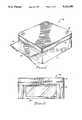
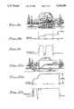
- FIG. 1is a perspective view illustrating a preferred embodiment of an enclosure useful with the sensor of the present invention.
- FIG. 2is a front elevation of the enclosure shown in FIG. 1.
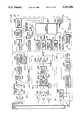
- FIG. 3is a block diagram illustrating the electronic and optics portions of the hardware used with the sensor of the present invention.
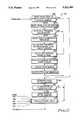
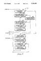
- FIGS. 4, 5 and 6are interrelated flow charts illustrating a preferred embodiment of the software useful with the present invention.
- FIGS. 7 and 8are perspective views illustrating the operation of the sensor of the present invention.
- FIG. 9Ais a side view illustrating an automobile of the type which may be sensed by the present invention
- FIGS. 9B and 9Care graphic representations of outputs actually provided by the sensor of the present invention relative to an automobile like that shown in FIG. 9A.
- FIG. 10Ais a side view illustrating a truck of the type which may be sensed by the present invention
- FIGS. 10B and 10Care graphic representations of outputs actually provided by the sensor of the present invention relative to a truck like that shown in FIG. 10A.
- FIG. 11is a schematic diagram of the time-to-amplitude circuit used in the present invention.
- a sensor in accordance with the present inventionis referred to generally by the reference numeral 10 in FIG. 1, and employs a compact enclosure 12 of light-weight material, such as aluminum.
- the enclosure 12has a cover 14 secured by fastener 16.
- Across one side of the enclosure 12is a transmissive window 20, which is shielded from ambient weather by a hood 18.
- the electrical-optical assemblyincludes a transmitter section 30, a receiver section 32, a range/processor section 34 and a power supply 36, each of which is discussed below.
- the transmitter section 30includes an astable multivibrator 303 generating a laser trigger pulse at a nominal repetition frequency of 3 kilohertz to a laser driver 304 which, by way of example, produces a 20 ampere peak current pulse with a 4 nanosecond rise time, and a ten nanosecond pulse width.
- the output of the laser drivercontrols a laser diode 306, which preferably comprises an indium gallium arsenide injection laser diode array having an output on the order of 180 watts, at the 20 ampere pulse current defined by the driver 304.
- This diodeemits an output at 905 nanometers, which has been found to be an ideal wavelength for the silicon photodiode receiver, discussed below.
- the array of the laser diode 306have a junction characterized by dimensions of about 3.96 millimeters by 0.002 millimeters, in order to emit radiation in a 10 degree by 40 degree solid angle.
- the output of the laser diode array 306is collected by a fast (F/1.6) multi-element optical lens 308 which has an effective focal length of 24 millimeters and which is used to collimate the diode laser emission, the resulting collimated beam passes through a dual-wedge prism 310.
- the two outputs of the dual-wedge prism 310are referred to by reference numerals 22 and 24. Both outputs are passed through the heated transmissive window 20.
- a 200 volt DC-DC converter 312is provided in the transmitter section 30 and preferably is contained within an aluminum enclosure (not shown) to reduce electrical interference.
- the transmitter section 30further includes an optical fiber 314 coupled to receive a simultaneous output from the laser diode 306 with the emission into the lens 308.
- the output passing through the optical fiber 314provides a significant aspect of the present invention, as is discussed in greater detail below with reference to the range/processor section 34.
- the receiver section 32includes lens 322 for receiving reflected returning energy from the two pulsed output beams 22, 24 emitted by the transmitter section 30.
- the energy passing through the lens 322is passed through an optical filter 324, and the single input from the lens 322-filter 324 is fed into two photodetectors 326, 328 each of which provides an input to a respective amplifier 327, 329 both of which provide an input to an analog multiplexer 332. It will thus be understood that the optical energy received in the lens 322 is first converted into an equivalent electronic analog of the input radiation and second into a logic-level signal.
- the outputs of the two photodetectors 326, 328are time-multiplexed by the high-speed analog multiplexer 332, which is controlled by a logic-level control line 333 from the microprocessor 352 contained within the range/processor section 34.
- the output of the multiplexer 332is connected to a threshold detector 336 and an amplifier 334, both of which provide inputs to the range/processor section, as described below.
- the two photodetectors 326, 328are silicon photodiodes which operate as current sources, with the associated amplifiers 327, 329 converting the current pulses of the photo detectors 326, 328 into voltage pulses.
- Each amplifier 327, 329offers a transimpedance of 28 kilohms when operated in a differential mode.
- the optical filter 324preferably has a narrowband (on the order of 40 nanometers) width, which limits the solar irradiance and permits only the 904 nanometer radiation to reach the photodetectors 326, 328.
- the transmission of the narrow-band filter 324is on the order of about 75 percent at 904 nanometers.
- the analog portion of the receiver section 32be contained within a faraday shield which permits the circuit to operate in a "field-free" region where the gain is achieved without additional noise reduction.
- the range/processor section 34includes a detector 342 optically coupled with the fiber 314, an amplifier 343 and a threshold detector 344, the output of which represents a "start" input to a range gate 346.
- the "stop” input for the range gate 346is provided as the output from the threshold detector 336 contained within the receiver section 32.
- the analog techniquehas been chosen in the present invention because of its better resolution, smaller size, simpler circuitry, lower power consumption and lower costs when compared with the digital technique.
- the analog range measurement technique specifically used in the present inventionis known as a "time-to-amplitude converter" and has an accuracy of about one percent of measured range and a resolution of about plus or minus 5 centimeters.
- the specific forms of the range gate 346 and the time-to-amplitude (TAC) converter circuit 348are shown in FIG. and use a constant-current source including transistor Q1 to charge a ramp capacitor C38 to obtain a linear voltage ramp whose instantaneous value is a measure of elapsed time.
- the TAC circuitis designed so that the voltage across the capacitor C38 begins ramping down from the positive power supply when the laser diode 306 fires. The ramp is stopped when either a reflected pulse is received at the detectors 326, 328 or at the end of a measured period of time.
- the output 349 of the TAC converter 348is then converted to a digital format by an 8 bit analog-to-digital converter inside the microprocessor 352 (FIG. 3).
- the start timing pulse for the TAC converter 348is produced utilizing the optical detection of the transmitted laser pulse through the fiber 314, which provides an input to the detector 342 and thence to the amplifier 343.
- the output of the amplifier 334 from the receiver section 32is provided as an input to a peak detector 350 which in turn provides an input to the microprocessor 352.
- a peak detector 350which in turn provides an input to the microprocessor 352.
- the microprocessor 352comprises an Intel 87C196KC into which the software described below is loaded. As noted in range/processor section 34 in FIG. 3, the microprocessor 352 provides various outputs to light emitting diode indicators 353, a presence relay 356 for indicating the presence of an object, an RS 232 computer interface 357 and to a heater relay 366 contained within the power supply 36, described below.
- the microprocessor 352receives additional inputs from a temperature sensor 351 and a real time clock 354.
- the range/processor section 334preferably also includes a battery backup circuit 358.
- the power supply section 36includes an EMI/surge protection circuit 362 for a power supply 364 operated by 110 volt line current.
- the power supply circuitincludes a heater relay 366 controlled by the microprocessor 352, as discussed above, and receiving 110 volts line power.
- the heater relayis coupled to the window 20, to maintain the temperature of the window 20 constant for varying ambient conditions.
- FIGS. 4-6A preferred embodiment of the software useful in connection with the sensor system and method of the present invention is illustrated in flow chart form in FIGS. 4-6, with the portions of the software depicted in each of those figures being arbitrarily designated by reference numerals 40, 42 and 44 respectively.
- the softwareis loaded in an object code format into the microprocessor 352, and is designed to control the electrical-optical assembly 28 of the sensor lo in order to detect the presence of objects and to provide certain desirable outputs representative of the object, including for example, the speed with which the object moves through the area being sensed, the size and shape of the object, its classification and perhaps other characteristics.
- the senor 10has utility as a vehicle sensor for mounting in an overhead configuration in order to detect the presence of vehicles passing through an area--such as a portion of a roadway at an intersection--to identify the presence of a vehicle, classify the vehicle as either an automobile, truck or motorcycle, count the number of vehicles passing through the intersection and calculate the speed of each vehicle and the flow rate of all of the vehicles.
- the software depicted in FIGS. 4-6has been specifically configured for those purposes.
- the softwareinitializes the microprocessor at 401, is subjected to diagnostics at 402 and then operates the electrical-optical assembly 28 to find the range to the road at 403.
- the softwaresets up the receiver to detect return beam 22, and the range and return-signal intensity is read; the range and intensity reading is then toggled between the two beams 22, 24 as controlled by section 433 in FIG. 5 (note input to the right of block of 405 in FIG. 4).
- any necessary offsetis added to the range based on the intensity to correct timing walk as depicted at step 406.
- the change in the rangei.e., the road distance minus the distance to any object detected
- a vehicle pulse counteris tested at 409 to determine if there have been 16 consecutive pulses above the vehicle threshold; if the calculation at step 407 is less than the vehicle threshold, then another sequence of steps is initiated at 421 (FIG. 5) to reset the vehicle pulse counter at 432 and thereby toggle between the beams 22, 24 at step 433.
- various resets and adjustmentsare made at steps 422-429, inclusive, including the calculation of the distance between the two beams at step 425 and the calculation of the average range to the road at 426 and the minimum/maximum range to the road at 427.
- step 409if the output of step 409 indicates that the number of consecutive pulses above the vehicle threshold is greater than 16, then the road pulse counter is reset at step 410. However, if the evaluation at step 409 is negative, then the vehicle pulse counter is incremented at step 448, and the road pulse counter is reset if it has previously incremented less than 16 times as indicated by steps 449 and 450; following this, the toggling between beams 22, 24 occurs at step 433.
- step 410if the road pulse counter is reset at step 410, then an inquiry is made as to whether the vehicle has already been detected; if the answer is affirmative, then an inquiry is made at step 441 to determine if the change in range determined at step 407 is greater than the truck threshold, as depicted at FIG. 6, in order to complete a truck-detection sequence at steps 442-446, inclusive.
- step 411FIG. 4
- the vehicle presence relayis set at step 412, a vehicle pulse counter is incremented at 413 and a velocity timer is started at step 415 for purposes of determining the speed of the vehicle passing through the area being sensed.
- the senor 10is depicted as elevated to a height H above a roadway 26, and is displaced at an angle ⁇ so as to be pointed toward an area on the roadway 26 defined by the beam separation W and the beam length L, and which is located a range distance R between the sensor 10 and the area.
- the sensor 10transmits two separate beams 22, 24 which fall upon the area defined by the length L and the width W. As shown in FIG.
- the microprocessor 352using the software and the various inputs from the electrical-optical assembly first measures the range to the road; if the range falls below a predetermined threshold, the microprocessor signals that a vehicle is present by closing the presence relay 356.
- the thresholdis determined by calculating the minimum, maximum and average range to the road for 100 discrete measurements.
- the maximum erroris then calculated by subtracting the average from the maximum range measurement and the minimum from the average range measurement.
- the thresholdis then set to the maximum error.
- the microprocessor 352utilizing the software classifies the vehicle detected (as, for example, an automobile, a truck or a motorcycle) by examining the amount of range change, it being understood that a truck produces a much larger range change than an automobile, and a motorcycle a much smaller range change.
- the softwarekeeps an accurate count of vehicles by classification for a predetermined period (for example, 24 hours) and in one example maintains a count of vehicle types for each hour of the day in order to provide a user flow rate.
- the microprocessor 352 and the associated softwarealso calculates the vehicle speed in the manner described above, by calculating the time each vehicle takes to pass between the two beams 22, 24. Specifically, the microprocessor 352 utilizes a microsecond time increment, and is reset to zero when the first beam 22 detects the presence of a vehicle, and is read when the vehicle is detected by the second beam. The software then automatically calculates the distance between the two beams 22, 24 by applying the law of cosines to the triangle formed by the two beams and the distance between them at the level of the roadway 26 in FIG. 7. The speed is then calculated by taking the distance between the beams and dividing it by the time the vehicle takes to travel that distance.
- the sensor 10can also be utilized to ascertain the existence of poor highway visibility conditions, which is useful in providing a warning to drivers to slow down because of dangerous visibility conditions.
- the amplitude of the return signal received by the vehicle sensoris proportional to the atmospheric transmittance (visibility). Analysis has shown that the sensor can detect vehicles until heavy fog or rainfall reduces the visibility range to 18 m. Corresponding to the change in visibility from clear day to foggy conditions, the received signal power decreased by a factor of 22. Thus, a measurement of the return-signal amplitude can be used to ascertain the existence of poor highway visibility conditions. If the microprocessor 352 senses a return-signal level from the roadway below a certain preselected threshold, then the software can initiate an output through the interface 357 to an appropriate visibility warning signal.
- a system according to the present inventionwas utilized as an overhead vehicle sensor on a roadway in Orange County, Fla.
- the sensorachieved a detection percentage of 99.4%, and measured speed with an accuracy equal to or greater than that of conventional radar guns used for traffic enforcement purposes.
- the systemalso provided vehicle range and intensity profiles, two examples of which are depicted in FIGS. 9A-C and 10A-C.
- FIG. 9Athe vehicle in question was a station wagon, and the range measurements for which are depicted at FIG. 9B, with the intensity measurements being depicted at FIG. 9C.
- the corresponding results of the range and intensity measurements for a truck shown at FIG. 10Aare depicted at FIGS. 10B and C, respectively.
Landscapes
- Physics & Mathematics (AREA)
- Engineering & Computer Science (AREA)
- Electromagnetism (AREA)
- General Physics & Mathematics (AREA)
- Remote Sensing (AREA)
- Radar, Positioning & Navigation (AREA)
- Computer Networks & Wireless Communication (AREA)
- Life Sciences & Earth Sciences (AREA)
- Insects & Arthropods (AREA)
- Pest Control & Pesticides (AREA)
- Wood Science & Technology (AREA)
- Zoology (AREA)
- Environmental Sciences (AREA)
- Optical Radar Systems And Details Thereof (AREA)
Abstract
Description
Claims (31)
Priority Applications (7)
| Application Number | Priority Date | Filing Date | Title |
|---|---|---|---|
| US07/980,273US5321490A (en) | 1992-11-23 | 1992-11-23 | Active near-field object sensor and method employing object classification techniques |
| AU57285/94AAU5728594A (en) | 1992-11-23 | 1993-11-22 | Active near-field object sensor and method employing object classification techniques |
| PCT/US1993/011366WO1994012851A1 (en) | 1992-11-23 | 1993-11-22 | Active near-field object sensor and method employing object classification techniques |
| US08/179,568US5546188A (en) | 1992-11-23 | 1994-01-10 | Intelligent vehicle highway system sensor and method |
| US08/693,667US5757472A (en) | 1992-11-23 | 1996-08-09 | Intelligent vehicle highway system sensor and method |
| US08/948,228US5896190A (en) | 1992-11-23 | 1997-10-09 | Intelligent vehicle highway system sensor and method |
| US09/479,517US6304321B1 (en) | 1992-11-23 | 2000-01-07 | Vehicle classification and axle counting sensor system and method |
Applications Claiming Priority (1)
| Application Number | Priority Date | Filing Date | Title |
|---|---|---|---|
| US07/980,273US5321490A (en) | 1992-11-23 | 1992-11-23 | Active near-field object sensor and method employing object classification techniques |
Related Parent Applications (1)
| Application Number | Title | Priority Date | Filing Date |
|---|---|---|---|
| US07/997,737Continuation-In-PartUS5278423A (en) | 1992-11-23 | 1992-12-30 | Object sensor and method for use in controlling an agricultural sprayer |
Related Child Applications (2)
| Application Number | Title | Priority Date | Filing Date |
|---|---|---|---|
| US07/997,737ContinuationUS5278423A (en) | 1992-11-23 | 1992-12-30 | Object sensor and method for use in controlling an agricultural sprayer |
| US08/179,568Continuation-In-PartUS5546188A (en) | 1992-11-23 | 1994-01-10 | Intelligent vehicle highway system sensor and method |
Publications (1)
| Publication Number | Publication Date |
|---|---|
| US5321490Atrue US5321490A (en) | 1994-06-14 |
Family
ID=25527458
Family Applications (1)
| Application Number | Title | Priority Date | Filing Date |
|---|---|---|---|
| US07/980,273Expired - LifetimeUS5321490A (en) | 1992-11-23 | 1992-11-23 | Active near-field object sensor and method employing object classification techniques |
Country Status (3)
| Country | Link |
|---|---|
| US (1) | US5321490A (en) |
| AU (1) | AU5728594A (en) |
| WO (1) | WO1994012851A1 (en) |
Cited By (34)
| Publication number | Priority date | Publication date | Assignee | Title |
|---|---|---|---|---|
| US5682229A (en)* | 1995-04-14 | 1997-10-28 | Schwartz Electro-Optics, Inc. | Laser range camera |
| DE19708014A1 (en)* | 1997-02-27 | 1998-09-10 | Ernst Dr Hoerber | Device and method for detecting an object in a predetermined spatial area, in particular vehicles for traffic monitoring |
| US5896190A (en)* | 1992-11-23 | 1999-04-20 | Schwartz Electro-Optics, Inc. | Intelligent vehicle highway system sensor and method |
| EP0823036A4 (en)* | 1995-04-28 | 1999-09-15 | Schwartz Electro Optics Inc | Intelligent vehicle highway system sensor and method |
| US6195157B1 (en)* | 1997-09-19 | 2001-02-27 | Honda Giken Kogyo Kabushiki Kaisha | Process for determining abnormality of detection in a distance sensor for a vehicle |
| US6304321B1 (en)* | 1992-11-23 | 2001-10-16 | Schwartz Electro-Optics, Inc. | Vehicle classification and axle counting sensor system and method |
| US6304096B1 (en)* | 1998-09-30 | 2001-10-16 | Siemens Aktiengesellschaft | Measuring device for measuring the intermediate circuit voltage of gradient amplifiers |
| US6404506B1 (en) | 1998-03-09 | 2002-06-11 | The Regents Of The University Of California | Non-intrusive laser-based system for detecting objects moving across a planar surface |
| US6596983B2 (en) | 2000-05-26 | 2003-07-22 | Mark R. Brent | Perimetric detection system and automated container |
| WO2003036320A3 (en)* | 2001-09-29 | 2003-07-24 | Vitronic Dr Ing Stein Bildvera | Method and device for measuring the speeds of moving objects |
| WO2003056526A3 (en)* | 2001-12-21 | 2003-08-28 | Siemens Ag | Device for monitoring spatial areas |
| US6732030B2 (en) | 2001-08-18 | 2004-05-04 | Snap-On U.K. Holdings Limited | Three-dimensional mapping systems for automotive vehicles and other articles |
| US20050146705A1 (en)* | 2003-12-24 | 2005-07-07 | Lei Jonathan S. | Range accuracy compensation circuit for single-shot laser rangefinders |
| US20050156102A1 (en)* | 2001-07-20 | 2005-07-21 | Walter Hagleitner | Optical sensor arrangement |
| US20050203641A1 (en)* | 2002-03-18 | 2005-09-15 | Sick Ag | Sensor-machine interface and method for operation thereof |
| US20050242306A1 (en)* | 2004-04-29 | 2005-11-03 | Sirota J M | System and method for traffic monitoring, speed determination, and traffic light violation detection and recording |
| US6974948B1 (en) | 2000-05-26 | 2005-12-13 | Brent Mark R | Perimetric detection system |
| US20050285738A1 (en)* | 2004-06-28 | 2005-12-29 | Antonios Seas | Compact single lens laser system for object/vehicle presence and speed determination |
| US20070008176A1 (en)* | 2005-06-13 | 2007-01-11 | Sirota J M | Traffic light status remote sensor system |
| US7181414B1 (en)* | 1998-09-16 | 2007-02-20 | Matsushita Electric Industrial Co., Ltd. | Electronic toll collection system for toll road |
| US20080036187A1 (en)* | 1992-05-05 | 2008-02-14 | Automotive Technologies International, Inc. | Vehicle-Mounted Monitoring Arrangement and Method Using Light-Regulation |
| EP1908275A4 (en)* | 2005-06-02 | 2009-11-18 | Transcore Link Logistics Corp | Optical cargo detection |
| US20110204145A1 (en)* | 2005-06-01 | 2011-08-25 | Bae Systems Information And Electronic Systems Integration Inc. | Method And Apparatus For Protecting Vehicles And Personnel Against Incoming Projectiles |
| US20120326914A1 (en)* | 2011-06-21 | 2012-12-27 | Kapsch Trafficcom Ag | Method and Apparatus for Detecting Vehicle Wheels |
| CN104011561A (en)* | 2011-12-23 | 2014-08-27 | 法雷奥开关和传感器有限责任公司 | Optical distance-measuring device and method for manufacturing a cover plate for a housing of an optical distance-measuring device |
| JP2015147481A (en)* | 2014-02-06 | 2015-08-20 | オムロン株式会社 | Movable body management device |
| CN106719524A (en)* | 2016-03-11 | 2017-05-31 | 深圳市镭神智能系统有限公司 | A kind of Intelligent Laser mosquito killing device and robot |
| CN111879237A (en)* | 2020-07-16 | 2020-11-03 | 广东焊将科技实业有限公司 | Laser scanning measurement and positioning method for carriage |
| US20200348397A1 (en)* | 2018-01-24 | 2020-11-05 | Denso Corporation | Lidar device |
| US20220028180A1 (en)* | 2020-07-27 | 2022-01-27 | Raytheon Company | Shape-based vehicle classification using laser scan and neural network |
| USD1000299S1 (en)* | 2021-06-07 | 2023-10-03 | Hesai Technology Co., Ltd. | Lidar |
| CN117213395A (en)* | 2023-09-16 | 2023-12-12 | 广州市西克传感器有限公司 | Semi-trailer head-hanging separation outline measurement system based on measurement grating and laser radar |
| USD1039406S1 (en)* | 2023-02-14 | 2024-08-20 | Banner Engineering Corp. | Fill sensor |
| USD1082572S1 (en)* | 2022-11-09 | 2025-07-08 | Hesai Technology Co., Ltd. | Detector |
Families Citing this family (1)
| Publication number | Priority date | Publication date | Assignee | Title |
|---|---|---|---|---|
| DE102020205650A1 (en)* | 2020-05-05 | 2021-11-11 | Robert Bosch Gesellschaft mit beschränkter Haftung | Test device for an active optical sensor |
Citations (23)
| Publication number | Priority date | Publication date | Assignee | Title |
|---|---|---|---|---|
| US3167739A (en)* | 1960-05-19 | 1965-01-26 | Honeywell Inc | Electronic object detector |
| US3436540A (en)* | 1966-04-08 | 1969-04-01 | Evr Eclairage Vehicules Rail | Photo-electrical vehicle detecting device for traffic survey |
| US3516056A (en)* | 1966-11-10 | 1970-06-02 | Lear Siegler Inc | Traffic control system |
| US3532886A (en)* | 1967-11-27 | 1970-10-06 | Sperry Rand Corp | Moving object detector using differentially combined optical sensors having intersecting axes |
| US3605082A (en)* | 1969-04-16 | 1971-09-14 | Laser Systems Corp | Intruder detection system |
| US3644917A (en)* | 1969-09-18 | 1972-02-22 | Detection Systems Inc | Single terminal electro-optical intruder detection device |
| US3680047A (en)* | 1970-12-15 | 1972-07-25 | Detection Systems Inc | Parametric integrator for condition-responsive systems |
| US3719938A (en)* | 1970-12-15 | 1973-03-06 | D Perlman | Photoelectric intruder detection device |
| US3852592A (en)* | 1973-06-07 | 1974-12-03 | Stanley Works | Automatic door operator |
| US3972021A (en)* | 1974-05-27 | 1976-07-27 | Ludwig Leitz | System for monitoring spaces by electro-optical means |
| US4317117A (en)* | 1979-07-20 | 1982-02-23 | Chasek Norman E | Cross correlated doppler radar/infra red velocity and presence sensor |
| US4433328A (en)* | 1980-01-16 | 1984-02-21 | Saphir Marc E | Motion sensing energy controller |
| US4569599A (en)* | 1982-04-28 | 1986-02-11 | Ludwig Bolkow | Method of determining the difference between the transit times of measuring pulse signals and reference pulse signals |
| US4699507A (en)* | 1984-03-27 | 1987-10-13 | Nissan Motor Company, Limited | Apparatus and method for measuring the distance to an object |
| US4699508A (en)* | 1981-06-09 | 1987-10-13 | Mtc Messtechnik Und Optelektronik Ag | Method of measuring the distance of a target and apparatus for its performance |
| US4716298A (en)* | 1984-06-01 | 1987-12-29 | Nissan Motor Company, Limited | System for automatically detecting presence or absence of a preceding vehicle and method therefor |
| US4734587A (en)* | 1984-05-23 | 1988-03-29 | Rudolf Schwarte | Optoelectric distance measuring apparatus with a time discriminator for the accurate detection of electric pulse sequence |
| US4888477A (en)* | 1988-11-03 | 1989-12-19 | Ford Aerospace Corporation | Range measurement for active optical recognition devices |
| US4948246A (en)* | 1988-02-22 | 1990-08-14 | Toyota Jidosha Kabushiki Kaisha | Leading-vehicle detection apparatus |
| US5054911A (en)* | 1988-12-30 | 1991-10-08 | Kabushiki Kaisha Topcon | Light wave distance measuring instrument of the pulse type |
| US5110203A (en)* | 1991-08-28 | 1992-05-05 | The United States Of America As Represented By The Secretary Of The Navy | Three dimensional range imaging system |
| US5118180A (en)* | 1990-02-24 | 1992-06-02 | Eltro Gmbh | Method and apparatus for determining the range of vision of a motor vehicle driver upon encountering fog or other obstacle |
| US5192979A (en)* | 1984-09-26 | 1993-03-09 | Siemens Aktiengesellschaft | Method and apparatus for recognizing and identifying targets |
- 1992
- 1992-11-23USUS07/980,273patent/US5321490A/ennot_activeExpired - Lifetime
- 1993
- 1993-11-22WOPCT/US1993/011366patent/WO1994012851A1/enactiveApplication Filing
- 1993-11-22AUAU57285/94Apatent/AU5728594A/ennot_activeAbandoned
Patent Citations (23)
| Publication number | Priority date | Publication date | Assignee | Title |
|---|---|---|---|---|
| US3167739A (en)* | 1960-05-19 | 1965-01-26 | Honeywell Inc | Electronic object detector |
| US3436540A (en)* | 1966-04-08 | 1969-04-01 | Evr Eclairage Vehicules Rail | Photo-electrical vehicle detecting device for traffic survey |
| US3516056A (en)* | 1966-11-10 | 1970-06-02 | Lear Siegler Inc | Traffic control system |
| US3532886A (en)* | 1967-11-27 | 1970-10-06 | Sperry Rand Corp | Moving object detector using differentially combined optical sensors having intersecting axes |
| US3605082A (en)* | 1969-04-16 | 1971-09-14 | Laser Systems Corp | Intruder detection system |
| US3644917A (en)* | 1969-09-18 | 1972-02-22 | Detection Systems Inc | Single terminal electro-optical intruder detection device |
| US3680047A (en)* | 1970-12-15 | 1972-07-25 | Detection Systems Inc | Parametric integrator for condition-responsive systems |
| US3719938A (en)* | 1970-12-15 | 1973-03-06 | D Perlman | Photoelectric intruder detection device |
| US3852592A (en)* | 1973-06-07 | 1974-12-03 | Stanley Works | Automatic door operator |
| US3972021A (en)* | 1974-05-27 | 1976-07-27 | Ludwig Leitz | System for monitoring spaces by electro-optical means |
| US4317117A (en)* | 1979-07-20 | 1982-02-23 | Chasek Norman E | Cross correlated doppler radar/infra red velocity and presence sensor |
| US4433328A (en)* | 1980-01-16 | 1984-02-21 | Saphir Marc E | Motion sensing energy controller |
| US4699508A (en)* | 1981-06-09 | 1987-10-13 | Mtc Messtechnik Und Optelektronik Ag | Method of measuring the distance of a target and apparatus for its performance |
| US4569599A (en)* | 1982-04-28 | 1986-02-11 | Ludwig Bolkow | Method of determining the difference between the transit times of measuring pulse signals and reference pulse signals |
| US4699507A (en)* | 1984-03-27 | 1987-10-13 | Nissan Motor Company, Limited | Apparatus and method for measuring the distance to an object |
| US4734587A (en)* | 1984-05-23 | 1988-03-29 | Rudolf Schwarte | Optoelectric distance measuring apparatus with a time discriminator for the accurate detection of electric pulse sequence |
| US4716298A (en)* | 1984-06-01 | 1987-12-29 | Nissan Motor Company, Limited | System for automatically detecting presence or absence of a preceding vehicle and method therefor |
| US5192979A (en)* | 1984-09-26 | 1993-03-09 | Siemens Aktiengesellschaft | Method and apparatus for recognizing and identifying targets |
| US4948246A (en)* | 1988-02-22 | 1990-08-14 | Toyota Jidosha Kabushiki Kaisha | Leading-vehicle detection apparatus |
| US4888477A (en)* | 1988-11-03 | 1989-12-19 | Ford Aerospace Corporation | Range measurement for active optical recognition devices |
| US5054911A (en)* | 1988-12-30 | 1991-10-08 | Kabushiki Kaisha Topcon | Light wave distance measuring instrument of the pulse type |
| US5118180A (en)* | 1990-02-24 | 1992-06-02 | Eltro Gmbh | Method and apparatus for determining the range of vision of a motor vehicle driver upon encountering fog or other obstacle |
| US5110203A (en)* | 1991-08-28 | 1992-05-05 | The United States Of America As Represented By The Secretary Of The Navy | Three dimensional range imaging system |
Non-Patent Citations (2)
| Title |
|---|
| The Urban Transportation Monitor, Jun. 8, 1990 "Overhead Infrared Vehicle Detection". |
| The Urban Transportation Monitor, Jun. 8, 1990 Overhead Infrared Vehicle Detection .* |
Cited By (52)
| Publication number | Priority date | Publication date | Assignee | Title |
|---|---|---|---|---|
| US20080036187A1 (en)* | 1992-05-05 | 2008-02-14 | Automotive Technologies International, Inc. | Vehicle-Mounted Monitoring Arrangement and Method Using Light-Regulation |
| US7655895B2 (en) | 1992-05-05 | 2010-02-02 | Automotive Technologies International, Inc. | Vehicle-mounted monitoring arrangement and method using light-regulation |
| US5896190A (en)* | 1992-11-23 | 1999-04-20 | Schwartz Electro-Optics, Inc. | Intelligent vehicle highway system sensor and method |
| US6304321B1 (en)* | 1992-11-23 | 2001-10-16 | Schwartz Electro-Optics, Inc. | Vehicle classification and axle counting sensor system and method |
| US5682229A (en)* | 1995-04-14 | 1997-10-28 | Schwartz Electro-Optics, Inc. | Laser range camera |
| EP0823036A4 (en)* | 1995-04-28 | 1999-09-15 | Schwartz Electro Optics Inc | Intelligent vehicle highway system sensor and method |
| DE19708014A1 (en)* | 1997-02-27 | 1998-09-10 | Ernst Dr Hoerber | Device and method for detecting an object in a predetermined spatial area, in particular vehicles for traffic monitoring |
| US6411221B2 (en) | 1997-02-27 | 2002-06-25 | Hoerber Ernst | Device and method to detect an object in a given area, especially vehicles, for the purpose of traffic control |
| US6195157B1 (en)* | 1997-09-19 | 2001-02-27 | Honda Giken Kogyo Kabushiki Kaisha | Process for determining abnormality of detection in a distance sensor for a vehicle |
| US6404506B1 (en) | 1998-03-09 | 2002-06-11 | The Regents Of The University Of California | Non-intrusive laser-based system for detecting objects moving across a planar surface |
| US7181414B1 (en)* | 1998-09-16 | 2007-02-20 | Matsushita Electric Industrial Co., Ltd. | Electronic toll collection system for toll road |
| US6304096B1 (en)* | 1998-09-30 | 2001-10-16 | Siemens Aktiengesellschaft | Measuring device for measuring the intermediate circuit voltage of gradient amplifiers |
| US6974948B1 (en) | 2000-05-26 | 2005-12-13 | Brent Mark R | Perimetric detection system |
| US6596983B2 (en) | 2000-05-26 | 2003-07-22 | Mark R. Brent | Perimetric detection system and automated container |
| US20050156102A1 (en)* | 2001-07-20 | 2005-07-21 | Walter Hagleitner | Optical sensor arrangement |
| US7236234B2 (en)* | 2001-07-20 | 2007-06-26 | Automotive Distance Control Systems Gmbh | Optical sensor arrangement |
| US6732030B2 (en) | 2001-08-18 | 2004-05-04 | Snap-On U.K. Holdings Limited | Three-dimensional mapping systems for automotive vehicles and other articles |
| WO2003036320A3 (en)* | 2001-09-29 | 2003-07-24 | Vitronic Dr Ing Stein Bildvera | Method and device for measuring the speeds of moving objects |
| US20050078297A1 (en)* | 2001-12-21 | 2005-04-14 | Gunter Doemens | Device for monitoring spatial areas |
| WO2003056526A3 (en)* | 2001-12-21 | 2003-08-28 | Siemens Ag | Device for monitoring spatial areas |
| US7274438B2 (en)* | 2001-12-21 | 2007-09-25 | Siemens Aktiengesellschaft | Device for monitoring spatial areas |
| US20050203641A1 (en)* | 2002-03-18 | 2005-09-15 | Sick Ag | Sensor-machine interface and method for operation thereof |
| US8050778B2 (en)* | 2002-03-18 | 2011-11-01 | Sick Ag | Sensor-machine interface and method for operation thereof |
| US20050146705A1 (en)* | 2003-12-24 | 2005-07-07 | Lei Jonathan S. | Range accuracy compensation circuit for single-shot laser rangefinders |
| US7616293B2 (en) | 2004-04-29 | 2009-11-10 | Sigma Space Corporation | System and method for traffic monitoring, speed determination, and traffic light violation detection and recording |
| US20050242306A1 (en)* | 2004-04-29 | 2005-11-03 | Sirota J M | System and method for traffic monitoring, speed determination, and traffic light violation detection and recording |
| US7323987B2 (en) | 2004-06-28 | 2008-01-29 | Sigma Space Corporation | Compact single lens laser system for object/vehicle presence and speed determination |
| US20050285738A1 (en)* | 2004-06-28 | 2005-12-29 | Antonios Seas | Compact single lens laser system for object/vehicle presence and speed determination |
| US20110204145A1 (en)* | 2005-06-01 | 2011-08-25 | Bae Systems Information And Electronic Systems Integration Inc. | Method And Apparatus For Protecting Vehicles And Personnel Against Incoming Projectiles |
| US8371202B2 (en)* | 2005-06-01 | 2013-02-12 | Bae Systems Information And Electronic Systems Integration Inc. | Method and apparatus for protecting vehicles and personnel against incoming projectiles |
| EP1908275A4 (en)* | 2005-06-02 | 2009-11-18 | Transcore Link Logistics Corp | Optical cargo detection |
| US20070008176A1 (en)* | 2005-06-13 | 2007-01-11 | Sirota J M | Traffic light status remote sensor system |
| US7495579B2 (en) | 2005-06-13 | 2009-02-24 | Sirota J Marcos | Traffic light status remote sensor system |
| US20120326914A1 (en)* | 2011-06-21 | 2012-12-27 | Kapsch Trafficcom Ag | Method and Apparatus for Detecting Vehicle Wheels |
| US8884812B2 (en)* | 2011-06-21 | 2014-11-11 | Kapsch Trafficcom Ag | Method and apparatus for detecting vehicle wheels |
| CN104011561B (en)* | 2011-12-23 | 2017-11-28 | 法雷奥开关和传感器有限责任公司 | Optical measuring device and method for producing a cover for a housing of an optical measuring device |
| CN104011561A (en)* | 2011-12-23 | 2014-08-27 | 法雷奥开关和传感器有限责任公司 | Optical distance-measuring device and method for manufacturing a cover plate for a housing of an optical distance-measuring device |
| US20140320845A1 (en)* | 2011-12-23 | 2014-10-30 | Valeo Schalter Und Sensoren Gmbh | Optical measuring device and a method for producing a cover disc for a housing of an optical measuring device |
| US9297901B2 (en)* | 2011-12-23 | 2016-03-29 | Valeo Schalter Und Sensoren Gmbh | Optical measuring device and a method for producing a cover disc for a housing of an optical measuring device |
| JP2015147481A (en)* | 2014-02-06 | 2015-08-20 | オムロン株式会社 | Movable body management device |
| CN106719524A (en)* | 2016-03-11 | 2017-05-31 | 深圳市镭神智能系统有限公司 | A kind of Intelligent Laser mosquito killing device and robot |
| CN106719524B (en)* | 2016-03-11 | 2023-10-31 | 深圳市镭神智能系统有限公司 | Intelligent laser mosquito eradication device and robot |
| US20200348397A1 (en)* | 2018-01-24 | 2020-11-05 | Denso Corporation | Lidar device |
| US11867839B2 (en)* | 2018-01-24 | 2024-01-09 | Denso Corporation | Lidar device heating optical window |
| CN111879237A (en)* | 2020-07-16 | 2020-11-03 | 广东焊将科技实业有限公司 | Laser scanning measurement and positioning method for carriage |
| US20220028180A1 (en)* | 2020-07-27 | 2022-01-27 | Raytheon Company | Shape-based vehicle classification using laser scan and neural network |
| US12039807B2 (en)* | 2020-07-27 | 2024-07-16 | Raytheon Company | Shape-based vehicle classification using laser scan and neural network |
| USD1000299S1 (en)* | 2021-06-07 | 2023-10-03 | Hesai Technology Co., Ltd. | Lidar |
| USD1036283S1 (en)* | 2021-06-07 | 2024-07-23 | Hesai Technology Co., Ltd. | Lidar |
| USD1082572S1 (en)* | 2022-11-09 | 2025-07-08 | Hesai Technology Co., Ltd. | Detector |
| USD1039406S1 (en)* | 2023-02-14 | 2024-08-20 | Banner Engineering Corp. | Fill sensor |
| CN117213395A (en)* | 2023-09-16 | 2023-12-12 | 广州市西克传感器有限公司 | Semi-trailer head-hanging separation outline measurement system based on measurement grating and laser radar |
Also Published As
| Publication number | Publication date |
|---|---|
| AU5728594A (en) | 1994-06-22 |
| WO1994012851A1 (en) | 1994-06-09 |
Similar Documents
| Publication | Publication Date | Title |
|---|---|---|
| US5321490A (en) | Active near-field object sensor and method employing object classification techniques | |
| US6304321B1 (en) | Vehicle classification and axle counting sensor system and method | |
| US5757472A (en) | Intelligent vehicle highway system sensor and method | |
| US5793491A (en) | Intelligent vehicle highway system multi-lane sensor and method | |
| US20020140924A1 (en) | Vehicle classification and axle counting sensor system and method | |
| US5118180A (en) | Method and apparatus for determining the range of vision of a motor vehicle driver upon encountering fog or other obstacle | |
| US5388048A (en) | Vehicle anti-collison device | |
| US4699507A (en) | Apparatus and method for measuring the distance to an object | |
| WO1998016801A1 (en) | Intelligent vehicle highway multi-lane sensor | |
| EP0473866B1 (en) | Collision avoidance system | |
| WO1996034252A1 (en) | Intelligent vehicle highway system sensor and method | |
| WO1996034252A9 (en) | Intelligent vehicle highway system sensor and method | |
| US20050242306A1 (en) | System and method for traffic monitoring, speed determination, and traffic light violation detection and recording | |
| EP0479273A2 (en) | Laser radar for a vehicle lateral guidance system | |
| US5978736A (en) | Vehicle obstruction detection system | |
| US6411221B2 (en) | Device and method to detect an object in a given area, especially vehicles, for the purpose of traffic control | |
| US5555036A (en) | Passive millimeter wave traffic sensor | |
| US6498570B2 (en) | Optical highway line detector | |
| CA2510975A1 (en) | System and method for traffic monitoring, speed determination, and traffic light violation detection and recording | |
| JPH08507371A (en) | Vehicle collision prevention device | |
| US7107144B2 (en) | Non-intrusive traffic monitoring system | |
| US20210110712A1 (en) | Device for detecting road surface water | |
| KR101893501B1 (en) | Integrated weather detector | |
| Ruiz-Llata et al. | LiDAR design for road condition measurement ahead of a moving vehicle | |
| US20040239528A1 (en) | Method and apparatus for measuring speed |
Legal Events
| Date | Code | Title | Description |
|---|---|---|---|
| AS | Assignment | Owner name:SCHWARTZ ELECTRO-OPTICS, INC., FLORIDA Free format text:ASSIGNMENT OF ASSIGNORS INTEREST.;ASSIGNORS:OLSON, ROBERT A.;GUSTAVSON, ROBERT L.;WANGLER, RICHARD J.;AND OTHERS;REEL/FRAME:006446/0402 Effective date:19921117 | |
| CC | Certificate of correction | ||
| FPAY | Fee payment | Year of fee payment:4 | |
| SULP | Surcharge for late payment | ||
| FPAY | Fee payment | Year of fee payment:8 | |
| AS | Assignment | Owner name:OSI DEFENSE SYSTEMS, LLC, FLORIDA Free format text:ASSIGNMENT OF ASSIGNORS INTEREST;ASSIGNOR:SCHWARTZ ELECTRO-OPTICS, INC.;REEL/FRAME:016418/0980 Effective date:20031112 Owner name:BANK OF THE WEST, A CALIFORNIA BANKING CORPORATION Free format text:SECURITY AGREEMENT;ASSIGNOR:OSI DEFENSE SYSTEMS, LLC;REEL/FRAME:016182/0877 Effective date:20050624 | |
| REMI | Maintenance fee reminder mailed | ||
| REIN | Reinstatement after maintenance fee payment confirmed | ||
| FP | Lapsed due to failure to pay maintenance fee | Effective date:20060614 | |
| FEPP | Fee payment procedure | Free format text:PETITION RELATED TO MAINTENANCE FEES FILED (ORIGINAL EVENT CODE: PMFP); ENTITY STATUS OF PATENT OWNER: SMALL ENTITY | |
| FEPP | Fee payment procedure | Free format text:PETITION RELATED TO MAINTENANCE FEES GRANTED (ORIGINAL EVENT CODE: PMFG); ENTITY STATUS OF PATENT OWNER: SMALL ENTITY | |
| PRDP | Patent reinstated due to the acceptance of a late maintenance fee | Effective date:20080207 | |
| STCF | Information on status: patent grant | Free format text:PATENTED CASE | |
| AS | Assignment | Owner name:WELLS FARGO BANK, NATIONAL ASSOCIATION, AS ADMINIS Free format text:NOTICE OF GRANT OF SECURITY INTEREST IN PATENTS;ASSIGNOR:OSI DEFENSE SYSTEMS, LLLC;REEL/FRAME:025150/0977 Effective date:20070727 | |
| AS | Assignment | Owner name:WELLS FARGO BANK, NATIONAL ASSOCIATION, AS ADMINIS Free format text:CORRECTIVE ASSIGNMENT TO CORRECT THE RECORDATION COVERSHEET WHICH INACCURATELY REFLECTS THE ASSIGNOR'S CORPORATE DESIGNATION AS LLLC AS OPPOSED TO THE CORRECT LLC PREVIOUSLY RECORDED ON REEL 025150 FRAME 0977. ASSIGNOR(S) HEREBY CONFIRMS THE COVER SHEET AND NOTICE OF GRANT OF SECURITY INTEREST TO BE A TRUE AND CORRECT COPY;ASSIGNOR:OSI DEFENSE SYSTEMS, LLC;REEL/FRAME:025178/0648 Effective date:20070727 |