US5320591A - Versatile exercise apparatus - Google Patents
Versatile exercise apparatusDownload PDFInfo
- Publication number
- US5320591A US5320591AUS08/041,833US4183393AUS5320591AUS 5320591 AUS5320591 AUS 5320591AUS 4183393 AUS4183393 AUS 4183393AUS 5320591 AUS5320591 AUS 5320591A
- Authority
- US
- United States
- Prior art keywords
- receiving
- body extremity
- user
- supporting
- extremity
- Prior art date
- Legal status (The legal status is an assumption and is not a legal conclusion. Google has not performed a legal analysis and makes no representation as to the accuracy of the status listed.)
- Expired - Lifetime
Links
- 210000003205muscleAnatomy0.000claimsdescription14
- 230000000284resting effectEffects0.000claimsdescription10
- 230000000670limiting effectEffects0.000claimsdescription3
- 239000013013elastic materialSubstances0.000claimsdescription2
- 210000003414extremityAnatomy0.000claims41
- 210000001217buttockAnatomy0.000claims3
- 238000000034methodMethods0.000abstractdescription3
- 230000008901benefitEffects0.000description20
- 230000006870functionEffects0.000description10
- 239000000463materialSubstances0.000description8
- 230000003387muscularEffects0.000description4
- 235000000396ironNutrition0.000description3
- 230000003189isokinetic effectEffects0.000description3
- 230000001747exhibiting effectEffects0.000description2
- 230000036541healthEffects0.000description2
- 239000002184metalSubstances0.000description2
- 230000003068static effectEffects0.000description2
- 238000003466weldingMethods0.000description2
- 208000027418Wounds and injuryDiseases0.000description1
- 230000000712assemblyEffects0.000description1
- 238000000429assemblyMethods0.000description1
- 239000002131composite materialSubstances0.000description1
- 230000006378damageEffects0.000description1
- 239000011152fibreglassSubstances0.000description1
- 208000014674injuryDiseases0.000description1
- 230000007794irritationEffects0.000description1
- 230000007246mechanismEffects0.000description1
- 230000008450motivationEffects0.000description1
- 238000000554physical therapyMethods0.000description1
- 230000009467reductionEffects0.000description1
- 230000002829reductive effectEffects0.000description1
- 230000000717retained effectEffects0.000description1
- 230000008961swellingEffects0.000description1
- 229920002994synthetic fiberPolymers0.000description1
- 238000002560therapeutic procedureMethods0.000description1
Images


Classifications
- A—HUMAN NECESSITIES
- A63—SPORTS; GAMES; AMUSEMENTS
- A63B—APPARATUS FOR PHYSICAL TRAINING, GYMNASTICS, SWIMMING, CLIMBING, OR FENCING; BALL GAMES; TRAINING EQUIPMENT
- A63B71/00—Games or sports accessories not covered in groups A63B1/00 - A63B69/00
- A63B71/0009—Games or sports accessories not covered in groups A63B1/00 - A63B69/00 for handicapped persons
- A—HUMAN NECESSITIES
- A63—SPORTS; GAMES; AMUSEMENTS
- A63B—APPARATUS FOR PHYSICAL TRAINING, GYMNASTICS, SWIMMING, CLIMBING, OR FENCING; BALL GAMES; TRAINING EQUIPMENT
- A63B23/00—Exercising apparatus specially adapted for particular parts of the body
- A—HUMAN NECESSITIES
- A63—SPORTS; GAMES; AMUSEMENTS
- A63B—APPARATUS FOR PHYSICAL TRAINING, GYMNASTICS, SWIMMING, CLIMBING, OR FENCING; BALL GAMES; TRAINING EQUIPMENT
- A63B71/00—Games or sports accessories not covered in groups A63B1/00 - A63B69/00
- A63B71/0009—Games or sports accessories not covered in groups A63B1/00 - A63B69/00 for handicapped persons
- A63B2071/0018—Games or sports accessories not covered in groups A63B1/00 - A63B69/00 for handicapped persons for wheelchair users
- A—HUMAN NECESSITIES
- A63—SPORTS; GAMES; AMUSEMENTS
- A63B—APPARATUS FOR PHYSICAL TRAINING, GYMNASTICS, SWIMMING, CLIMBING, OR FENCING; BALL GAMES; TRAINING EQUIPMENT
- A63B71/00—Games or sports accessories not covered in groups A63B1/00 - A63B69/00
- A63B71/02—Games or sports accessories not covered in groups A63B1/00 - A63B69/00 for large-room or outdoor sporting games
- A63B71/023—Supports, e.g. poles
- A63B2071/025—Supports, e.g. poles on rollers or wheels
- A—HUMAN NECESSITIES
- A63—SPORTS; GAMES; AMUSEMENTS
- A63B—APPARATUS FOR PHYSICAL TRAINING, GYMNASTICS, SWIMMING, CLIMBING, OR FENCING; BALL GAMES; TRAINING EQUIPMENT
- A63B21/00—Exercising apparatus for developing or strengthening the muscles or joints of the body by working against a counterforce, with or without measuring devices
- A63B21/02—Exercising apparatus for developing or strengthening the muscles or joints of the body by working against a counterforce, with or without measuring devices using resilient force-resisters
- A63B21/04—Exercising apparatus for developing or strengthening the muscles or joints of the body by working against a counterforce, with or without measuring devices using resilient force-resisters attached to static foundation, e.g. a user
- A63B21/0407—Anchored at two end points, e.g. installed within an apparatus
- A63B21/0414—Anchored at two end points, e.g. installed within an apparatus with both ends stationary during the actual exercise, i.e. moving only at intermediate locations
- A—HUMAN NECESSITIES
- A63—SPORTS; GAMES; AMUSEMENTS
- A63B—APPARATUS FOR PHYSICAL TRAINING, GYMNASTICS, SWIMMING, CLIMBING, OR FENCING; BALL GAMES; TRAINING EQUIPMENT
- A63B21/00—Exercising apparatus for developing or strengthening the muscles or joints of the body by working against a counterforce, with or without measuring devices
- A63B21/02—Exercising apparatus for developing or strengthening the muscles or joints of the body by working against a counterforce, with or without measuring devices using resilient force-resisters
- A63B21/055—Exercising apparatus for developing or strengthening the muscles or joints of the body by working against a counterforce, with or without measuring devices using resilient force-resisters extension element type
- A63B21/0552—Elastic ropes or bands
- A63B21/0557—Details of attachments, e.g. clips or clamps
- A—HUMAN NECESSITIES
- A63—SPORTS; GAMES; AMUSEMENTS
- A63B—APPARATUS FOR PHYSICAL TRAINING, GYMNASTICS, SWIMMING, CLIMBING, OR FENCING; BALL GAMES; TRAINING EQUIPMENT
- A63B2208/00—Characteristics or parameters related to the user or player
- A63B2208/02—Characteristics or parameters related to the user or player posture
- A63B2208/0228—Sitting on the buttocks
- A—HUMAN NECESSITIES
- A63—SPORTS; GAMES; AMUSEMENTS
- A63B—APPARATUS FOR PHYSICAL TRAINING, GYMNASTICS, SWIMMING, CLIMBING, OR FENCING; BALL GAMES; TRAINING EQUIPMENT
- A63B2208/00—Characteristics or parameters related to the user or player
- A63B2208/02—Characteristics or parameters related to the user or player posture
- A63B2208/0242—Lying down
Definitions
- This inventionrelates generally to exercise apparatus and more specifically to a novel apparatus for exercising which combines the principles of isometrics and isotonics.
- isometricswhich is a static form of exercise wherein the joints are moved at a constant speed (0 degrees per second) against a constant resistance, that is, with no observable joint movement. For example, pushing the palms of the hands against one another is an isometric exercise. Studies indicate that isometric exercise increases strength primarily at the specific angle assumed by the joint when force is applied.
- the second form of resistanceis isotonics and involves movement of a joint throughout a range of motion against a constant resistance.
- the best example of isotonic exerciseis the use of barbells or similar free weights.
- traditional isotonicsthere is no way to accommodate for biomechanical leverage changes that increase and decrease muscular efficiency throughout the range of motion. Therefore, the dynamically contracting muscle is only loaded maximally at its weakest point in the range of motion.
- the third basic type of resistance exerciseis isokinetics and entails exercise performed at a constant speed with totally accommodating resistance throughout the entire range of motion.
- This form of exerciserequires specially designed, complex, and expensive equipment, and usually requires constant supervision. Therefore, exercise apparatus utilizing the principle of isokinetics are generally not well suited to the individual who may wish to exercise within the confines of his own home or who cannot afford the great expense of such apparatus.
- isometric exercisesprovide the following important advantages: less joint irritation since there is no joint motion, increase of static muscular strength, reduction in swelling of joints, and isometric exercises can be performed anywhere in relatively short periods of time.
- an exercise apparatusutilizing both isometrics and isokinetics would obviate the above-mentioned problem associated with isotonic exercise of maximally loading the dynamically contracting muscle at only its weakest point. Instead, the apparatus could be adjusted such that maximal loading could occur at any of the several points along its limited range of motion.
- an exercise apparatuscombining the advantages of both isometric and isotonic exercise would be a great advance in the art. Moreover, such an apparatus would have great benefits as a physical therapy device for use by those who have suffered an injury or who have reduced capacity for exercise.
- a principle object of this inventionis to provide a combined isometric/isotonic resistance exercise apparatus providing the advantages inherent in both of these resistance methods.
- the exercise apparatus of the present inventioncomprises generally means for receiving a body extremity, said means for receiving a body extremity receiving a directional force provided by the body extremity, said force resulting in limited movement of the means for receiving a body extremity; means for maintaining the means for receiving a body extremity in a predefined plane during movement; and means for providing resistance to movement upon application of the force to the means for receiving a body extremity.
- the means for receiving a body extremitycomprises a horizontally disposed bar to be grasped or otherwise contacted by a body extremity, such as a hand.
- a body extremitysuch as a hand.
- one or more slingsis provided into which a body extremity is inserted.
- a preferred means for maintaining the means for receiving a body extremity in a predefined plane during movementcomprises a cylindrical sleeve securely attached to each end of the horizontally disposed bar, each sleeve being slidably mounted on a vertically disposed post.
- the two postscombine to form a plane within which movement of the bar is limited.
- the predefined planecan be either flat or curved.
- each slingis securely attached to one of the sleeves.
- the slingscan be used in cooperation with the horizontally disposed bar, e.g. attached thereto.
- the means for providing resistancepreferably comprises a cord formed of a material exhibiting elastic properties which is securely attached near the bottom and top end of each vertically disposed post.
- each cordIn order to provide the desired resistance, each cord must be maintained in a taut configuration. Further, each cord is securely attached near its midsection to one of the sleeves slidably mounted on the vertically disposed posts. In this manner, the horizontally disposed bar, or, in the alternative, each sling or other body part receiving structure, is secured in place.
- This inventionmay also include a support structure, depending upon the intended use thereof.
- the apparatusmay be self supporting and include a bench or chair upon which the user sits or lays.
- Such free-standing embodiments of the present inventionmay be adapted to provide access to a wheelchair so that person confined to the wheelchair can obtain the advantages of the invention.
- the apparatusmay be adapted for connection to a standard hospital bed so that a person confined thereto can also obtain the advantages of the invention.
- the usergrasps the bar or slings, or otherwise contacts the same, and exerts a force.
- the vertical position of the barcan be varied to accommodate different positions for a body extremity.
- the bar or slingsmay be pushed or pulled upwardly or downwardly by a variety of body extremities or parts, as desired, to work the muscle group to be exercised. Responsive to the force exerted, the bar or sling will move only slightly within the plane defined by the vertically disposed posts. By limiting the movement of the bar or slings to a slight distance, regardless of the force exerted, the benefits of both isometric and isotonic resistance exercises are effectively combined.
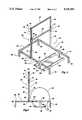
- FIG. 1is a perspective view of a presently preferred embodiment of the present invention intended for general purpose use
- FIG. 2is a side elevational view of the embodiment represented in FIG. 1;
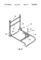
- FIG. 3is a perspective view of another preferred embodiment of the present invention adapted specifically for users confined to a wheelchair;
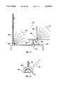
- FIG. 4is a side elevational view of the embodiment represented in FIG. 3 further illustrating the position of a typical wheelchair wheel;
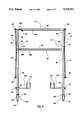
- FIG. 5is a front elevational view of still another preferred embodiment of the present invention specifically adapted for users confined to a bed;
- FIG. 6is an enlarged elevational fragmentary view illustrating attachment of the flexible and elastic cord to a slidable sleeve
- FIG. 7is an enlarged elevational fragmentary view, according to the embodiment represented in FIG. 5, illustrating the attachment of the flexible and elastic cord near the top of a vertical post and further illustrating the securing of telescoping cross members after adjustment thereof;
- FIG. 8is an enlarged elevational fragmentary view of the preferred manner in which the flexible and elastic cord is attached near the top of a vertically disposed post;
- FIG. 9is an enlarged elevational fragmentary view of the structures which can preferably be used to allow the components of the illustrated embodiments to be adjustably positioned.
- FIG. 10is a perspective view of another embodiment of the present invention.
- FIG. 11is a side elevational view of the embodiment illustrated in FIG. 10.
- FIG. 12is a detailed elevational view of a portion of the embodiment illustrated in FIG. 11.
- FIG. 1a first presently preferred embodiment of the present invention, generally designated 20, is illustrated.
- the embodiment of FIG. 1comprises one example of a means for receiving a body extremity of a user 22.
- the structures generally designated at 22function as one presently preferred example of a means for receiving a body extremity of a user.
- the means for receiving a body extremityis subject to a force provided by the user (e.g., by an arm or a leg) and this force results in limited movement of the means for receiving a body extremity 22.
- FIG. 1Also illustrated in FIG. 1 is one preferred structural arrangement of a means, comprising the structures generally designated at 24, for maintaining the means for receiving a body extremity 22 in a predefined plane during movement.
- a meanscomprising the structures generally designated at 24, for maintaining the means for receiving a body extremity 22 in a predefined plane during movement.
- such movementis limited to a flat predefined plane but may also include curved planes or a flat plane oriented at a nonvertical angle.
- the means for receiving a body extremity of a user 22, in its preferred form,is a rigid horizontal bar 28, which is formed of a suitable strong and rigid material. As shown in FIGS. 1 and 3, the bar 28 has two ends, both ends being securely attached to the sleeve 26 which function as part of the means for maintaining the means for receiving a body extremity in a predefined plane during movement.
- the means for receiving the body extremitymay be carried out by at least one sling 30 into which a body extremity can be inserted.
- FIG. 6illustrates the sling 30 as being attached to a sleeve 36 as explained hereafter. Attachment thereof may be made by a bolt 32 in combination with a washer 34, the bolt 32 passing through apertures, not shown, formed in both ends of the sling 30, as well as through the washer 34.
- the sling 30may be slidably attached to the rigid crossbar 28.
- the sling 30may be attached in any of a number of different ways to the means 24, and that the attachment assembly shown in FIG. 6 is merely illustrative.
- the means for receiving a body extremity of a usermay have a different form than the bar 28 or the sling 30, without departing from the scope of this invention.
- a rigid handle attached to a supporting structure on one of its endsmay also be used within the scope of the present invention.
- the means for maintaining the means for receiving a body extremity in a predefined plane during movementfurther limits such movement to one dimension. In other embodiments, it may allow movement in a curved plane.
- the preferred structures for carrying out the means for maintaining the means for receiving a body extremity in a predefined plane during movementis best shown in FIGS. 1 through 6.
- the means for maintainingcomprises two sleeves 36 attached to the rigid bar 28 (which functions as a means for receiving a body extremity) and a post 38 upon which each sleeve 36 is slidably mounted.
- each sleeve 36is preferably cylindrical in shape and includes a hollow central portion 40.
- the post 38 upon which each sleeve 36 is slidably mountedpasses through the central portion 40 of the sleeve 36.
- the posts 38are generally oriented in an upright position, and preferably disposed vertically to provide a vertical range of motion, and parallel, thus defining a flat plane. It is also within the scope of the present invention to dispose the posts 38 at an angle other than vertical.
- Each of the two parallel posts 38is formed of a rigid material, for example a metal, and should have a fairly smooth exterior surface such that the sleeve 36 mounted on each post 38 slides freely thereon.
- the posts 38may be characterized as including top, middle and bottom portions.
- the bottom portions of each post 38are preferably fixedly attached to a base, as detailed hereafter.
- a crossbar 42connects the top portions of the two parallel posts 38 together.
- the crossbar 42has two ends, one end being fixedly attached to the top portion of each of the posts 38. This connection may be made in any manner known in the art. As shown in FIG. 7, the preferred connection is made by a weld joining the post 38 and the crossbar 42.
- Each sleeve 36should be rigid and sized so as to accept one of the posts 38 in the hollow central portion 40 thereof in a snug, but not tight, slidable relationship. It will be apparent to one skilled in the art that the two upright parallel posts 38, in combination with the sleeves 36, define a flat plane within which movement of the attached means for receiving a body extremity, i.e.. rigid bar 28, is limited.
- the preferred component for carrying out this functionis formed from an elongated piece of material exhibiting elastic properties, such as a flexible cord 44. While other materials, such as a sheet of elastic material or even a pneumatic or hydraulic device (either actively power driven passive), are contemplated and fall within the purview of this invention, the preferred structure for providing resistance to movement is the flexible cord 44 which in one form is commonly referred to as "surgical tubing.”
- the resistance to movement provided by the flexible cord 44is determined by the diameter thereof.
- the flexible cord 44is pulled to a desired tautness and the first end of the flexible cord 44 is connected to or near the top portion of a post 38 and the second end of the flexible cord 44 is connected to the bottom portion of a post 38, as shown in FIG. 5.
- the second end of the flexible cord 44is connected to a base, such as shown in FIGS. 1 through 4 and described hereafter.
- some portion of the flexible cord 44is connected to the sleeve 36.
- clamps 45may be arranged so that they releasably grip the flexible cord 44. This will allow the position of the sleeve 36 relative to the length of the flexible cord to be adjusted. In some circumstances, e.g., accommodating differing size users, adjusting the relative position of the sleeve 36 and the flexible cord 44 will be advantageous.
- FIGS. 6 through 8illustrate a preferred flexible cord 44 and the manner in which it is attached to the post 38 and the sleeve 36, as mentioned.
- Both the first and second ends of the cord 44comprise an integrated loop 46 (FIG. 8), although it should be recognized that the loop 46 may be formed in any manner known in the art.
- hooks 48 and 50are securely attached, as by welding, near the top of each post 38, preferably to the crossbar 42, and bottom portion of each post 38, respectively.
- the bottom hook 50may be fixedly attached to a base, described later herein.
- the middle portion of the flexible cord 44is attached to a sleeve 36. See FIG. 6. With the top and bottom end portions of the cord 44 looped about top and bottom hooks 48 and 50, respectively, and the middle portion of the cord 44 attached to a sleeve 36, the rigid bar (28 in FIG. 1) or the sling (30 in FIG. 6), which function as means for receiving a body extremity, is held in place ready to receive a body extremity.
- the flexible cord 44provides resistance to movement upon application of a force to the means for receiving a body extremity.
- the apparatus 20includes structural means such as a base, generally designated at 52, which is self supporting.
- the base 52 of FIGS. 1 and 2is formed of a rigid material and comprises a rectangular frame portion 54, a supporting leg 56 disposed at each corner of the rectangular frame portion 54, and an adjustable positioner assembly, generally designated at 58, for maintaining the user in a proper position relative to the other structures of the embodiment.
- the adjustable positioner assembly 58comprises a cross member 60 which is slidably mounted to opposing members of the frame portion 54, and an adjustable seat, generally designated at 62, upon which the user may sit or lay during operation of the illustrated apparatus.
- the cross member 60includes integrated sleeves 64 through which opposing members of the frame portion 54 pass, similar to the relationship between each sleeve 36 and post 38.
- each integrated sleeve 64may include an aperture 66 which at certain positions corresponds, to one of a series of apertures 68 drilled or otherwise formed in the opposing members of the frame portion 54 to which the cross member 60 is mounted. A pin, or other similar well-known implement, not shown, may then be passed through aligned apertures 66 and 68 to secure the crossbar 60 in place during use.
- the adjustable positioner assembly 58further comprises the adjustable seat, 62, which includes a pair of seat members 70 and 72 which are adjustable relative to each other between a coplanar position and a noncoplanar position, and an adjustable stem 74 by which the height of the adjustable seat 62 is manipulated.
- the adjustable stem 74is shown seated in a collar 76 which is fixedly attached to the cross member 60, near the center thereof.
- the collar 76includes an aperture 78 which may be aligned with one of a series of apertures 80 drilled or otherwise formed in the stem 74.
- a pin, or other similar implement known in the art(not shown) is inserted through aligned apertures 78 and 80 to secure the adjustable seat 62 at the desired height.
- the seat member 70is preferably horizontal in orientation and is securely attached (as by welding) to the top end of the adjustable stem 74.
- the second seat member 72is hingedly attached to the first seat member 70, thereby allowing for adjustment of the two seat members 70 and 72 between a coplanar and a noncoplanar relationship.
- the hinged connectionmay be made by a bolt 82 which passes through aligned apertures, not shown, in both of the seat members 70 and 72 near the edges thereof. A corresponding nut, not shown, would secure the bolt 82 in place.
- the seat members 70 and 72may be padded to ensure the comfort of a user.
- FIGS. 3 and 4An alternative embodiment of the present invention 23, which includes a modified base 52, is illustrated in FIGS. 3 and 4.
- the embodiment illustrated in FIGS. 3 and 4is specifically adapted for operation by a user confined to a wheelchair.
- This embodimentincludes a generally U-shaped frame portion 84, a supporting leg 86 disposed at each corner of the U-shaped frame portion 84 and another adjustable positioner assembly 96.
- the frame portion 84 and the supporting legs 86are nearly identical to the frame portion 54 and supporting legs 56 of the embodiment of FIGS. 1 and 2, except that the frame portion 84 does not form a complete rectangle.
- One of the members of the frame portion 84is absent to allow access to the adjustable positioner assembly, generally indicated at 88, by a wheelchair.
- the adjustable positioner assembly 88comprises a platform 90 which includes angle irons 92 and 94 welded or otherwise attached to the longitudinal edges thereof and T-shaped sleeves 96 by which the platform 90 is slidably mounted to opposing members of the frame portion 84.
- the platform 90is formed of a rigid plate material, for example metal, fiberglass, or a composite or some other synthetic material, and disposed so as to rest on the surface supporting the apparatus 23.
- the angle irons 92 and 94are also preferably formed of a rigid and durable material.
- the sleeves 96are similar to the sleeves 64 of the embodiment shown in FIGS. 1 and 2, except that each is connected to the platform 90 which accommodates a wheelchair, rather than to the crossbar 60 upon which the adjustable seat 62 is mounted. Each sleeve 96 is fixedly attached to the platform 90.
- each sleeve 96function similarly to the sleeves 64 in that each sleeve 96 has an aperture 98, preferably identical to the aperture 66 (FIGS. 1 and 2), and is aligned with one in a series of apertures 100 in the frame portion 84, preferably identical to the series of apertures 68 (FIGS. 1 and 2) in the frame portion 54.
- a wheelchair(not completely illustrated) having a wheel 102, is positioned on the platform 90 and the angle irons 92 and 94 prevent movement thereof during use and the sleeves 96 make the position of the platform 90 adjustable relative to the rigid bar 28.
- FIG. 5another embodiment of the present invention, generally indicated at 21, is shown.
- the embodiment illustrated in FIG. 5is particularly intended for connection to a hospital bed or the like.
- the bar 28 and the crossbar 42each comprise two separate telescoping members (28A-B and 42A-B, respectively), the crossbar 42 including a screw 104 for securing the telescoping members in the desired position.
- the apparatus 21can be adjusted to fit beds having differing widths.
- the parallel posts 38are extended and include at the bottom portions thereof wheel assemblies, generally indicated at 106, to assist in transporting the apparatus 21 to and from the bed.
- Each post 38further includes adjustable clamps, generally designated at 108, by which the apparatus 21 may be temporarily connected to the frame of the bed in which the user is confined.
- the clamps 108include a collar 110 which can be adjustably positioned along the length of the post 38 by a screw 112, and a set of receiving jaws 114.
- the receiving jaws 114have a standard locking mechanism, not shown, by which the jaws 114 are locked into a fixed position about the frame of the bed.
- the wheel assembly 106is common in the art and may include a wheel 116 rotatably mounted between parallel arms 118 and 120, an axle, not shown, passing through both arms 118 and 120, as well as through the center of the wheel 116. It may be desirable to include a pair of wheels or casters in place of wheels 116 so that the apparatus 21 will be free standing for transport and storage.
- the bottom hook 50which secures the bottom portion of the cord 44, is fixedly attached to the bottom portion of the post 38.
- FIGS. 10-12illustrate another preferred embodiment of the present invention.
- the embodiment of FIGS. 10-12shares the essential characteristics of the structures illustrated in FIGS. 1-9 with additional desirable structures added thereto.
- the structures represented in FIGS. 10-12provide the important advantage of allowing the angular orientation of pertinent structures to be varied so that the relationship between the user's body and a rigid horizontal bar assembly, generally designated at 156, can be carefully selected and retained during exercise so that maximum benefit to the use can be obtained. It will be understood that selecting and retaining the proper relationship between the user's body and the bar assembly 156 is important to obtaining maximum benefit for the user by allowing a particular muscle group or groups to be exercised.
- a frame 152is provided.
- a seat support assemblyis generally designated at 154.
- the seat support assembly 154is the presently preferred arrangement for the means for supporting the user's body.
- the seat support assembly 154is shown as a skeleton ready to receive, for example, upholstered pads (not illustrated).
- the seat support assembly 154can be adjustably positioned along the frame 152 in a manner similar to that described earlier herein in connection with cross bar 60 and sleeves 64 (FIGS. 1 and 2).
- the illustrated arrangementis the preferred structure for providing a means for adjusting the distance between the seat and the horizontal bar assembly 156.
- a seat back support 164is also provided with a pivoting structure 16 which allows the angular orientation of the seat back support 164 to be adjusted and held in place. Also, similarly to the function described earlier herein for the adjustable seat 62 (FIGS. 1 and 2), the height of the seat support assembly 154 can be adjusted using the illustrated means for adjusting the height of the seat support assembly. Furthermore, as will be explained more fully shortly, the seat support assembly 154 can also be rotated.
- FIG. 10Also illustrated in FIG. 10 are two posts 166 which function to keep the movement of the horizontal bar assembly 156 in a predefined plane similarly to the earlier described corresponding structures.
- pivoting structures 160are provided to orient the predefined plane in which the horizontal bar assembly 156 moves in any one of a plurality of angular orientations.
- a crossbar 176connects the two posts 166 together and assists with keeping the posts 166 parallel.
- the seat support assembly 154can be adjusted vertically (arrow 168), rotated (arrow 172), and positioned horizontally (arrow 172). These adjustments allow the orientation of the seat support assembly 154 to be altered in three planes in relation to the horizontal bar assembly 156. Moreover, the pivoting structure 162 allows the seat back support 164 to be adjusted to any one of the plurality of angular positions in the plane represented by arrow 174.
- FIG. 11Also represented in FIG. 11 is a pivoting structure 160 which allows the angular orientation of the posts 166 to be altered and held in any of a plurality of positions in the plane represented by arrow 165.
- FIG. 12provides a detailed view of the pivoting structure 160 and the angular orientations provided thereby.
- the pivoting structures 160 and 162are the preferred structures for carrying out the means for pivoting of the present invention. It is preferred that the illustrated pivoting structures 160 and 162 can usefully provide an angular range of anywhere from one-hundred and eighty degrees to fifteen degrees. It is most preferred that the pivoting structures 160 and 162 provide an angular range of ninety about degrees or about forty-five degrees.
- pivoting structures 160 and 162may be inserted into bores 178 (identified in FIG. 12) of the pivoting structures 160 and 162 or some other arrangement can be used.
- FIGS. 10 and 11provide even more flexibility and benefit for the user than if angular adjustment for just one component were provided.
- the orientation of the user's body in relation to the horizontal bar assembly 156can be specifically adjusted and held in place.
- Some embodiments of the present inventionmay have all, or just some, of the adjusting structures represented in FIGS. 10-12. Moreover, the structures represented in FIGS. 10-12 can be combined with those illustrated in FIGS. 1-9 to arrive at additional embodiments falling within the scope of the present invention.
Landscapes
- Health & Medical Sciences (AREA)
- General Health & Medical Sciences (AREA)
- Physical Education & Sports Medicine (AREA)
- Rehabilitation Tools (AREA)
- Invalid Beds And Related Equipment (AREA)
Abstract
Description
Claims (20)
Priority Applications (3)
| Application Number | Priority Date | Filing Date | Title |
|---|---|---|---|
| US08/041,833US5320591A (en) | 1991-05-10 | 1993-04-01 | Versatile exercise apparatus |
| US08/259,037US5478299A (en) | 1991-05-10 | 1994-06-13 | Adaptable exercise apparatus |
| US08/481,807US5913749A (en) | 1991-05-10 | 1995-06-07 | Adaptable range-of-motion exercise apparatus |
Applications Claiming Priority (2)
| Application Number | Priority Date | Filing Date | Title |
|---|---|---|---|
| US69839991A | 1991-05-10 | 1991-05-10 | |
| US08/041,833US5320591A (en) | 1991-05-10 | 1993-04-01 | Versatile exercise apparatus |
Related Parent Applications (1)
| Application Number | Title | Priority Date | Filing Date |
|---|---|---|---|
| US69839991AContinuation-In-Part | 1991-05-10 | 1991-05-10 |
Related Child Applications (1)
| Application Number | Title | Priority Date | Filing Date |
|---|---|---|---|
| US08/259,037Continuation-In-PartUS5478299A (en) | 1991-05-10 | 1994-06-13 | Adaptable exercise apparatus |
Publications (1)
| Publication Number | Publication Date |
|---|---|
| US5320591Atrue US5320591A (en) | 1994-06-14 |
Family
ID=24805077
Family Applications (1)
| Application Number | Title | Priority Date | Filing Date |
|---|---|---|---|
| US08/041,833Expired - LifetimeUS5320591A (en) | 1991-05-10 | 1993-04-01 | Versatile exercise apparatus |
Country Status (3)
| Country | Link |
|---|---|
| US (1) | US5320591A (en) |
| AU (1) | AU2005492A (en) |
| WO (1) | WO1992020409A1 (en) |
Cited By (59)
| Publication number | Priority date | Publication date | Assignee | Title |
|---|---|---|---|---|
| US5478299A (en)* | 1991-05-10 | 1995-12-26 | Harmon; Larry S. | Adaptable exercise apparatus |
| US5518479A (en)* | 1995-03-15 | 1996-05-21 | Young; Darel | Variable resistance leg exercising device |
| US5529560A (en)* | 1993-06-08 | 1996-06-25 | David Dise | Stretch therapy apparatus for physical fitness, rehabilitation and medical treatment |
| US5624360A (en)* | 1992-12-03 | 1997-04-29 | Wilkins; Chester | Total gym |
| US5653670A (en)* | 1992-09-04 | 1997-08-05 | Endelman; Ken | Exercise apparatus |
| US5662564A (en)* | 1996-05-15 | 1997-09-02 | Nelson; Keith A. | Exercise device |
| US5810702A (en)* | 1996-07-30 | 1998-09-22 | Wilkinson; William T. | Portable exercise device |
| US5836859A (en)* | 1997-06-12 | 1998-11-17 | Van Herle; Philippe Johan | Full body exercise machine |
| US5997448A (en)* | 1998-06-11 | 1999-12-07 | Duba; Alex | Physical exercising station |
| US6328679B1 (en)* | 2000-06-19 | 2001-12-11 | Ellen Croft | Wall-mountable exercise device |
| US6416447B1 (en) | 1999-06-21 | 2002-07-09 | Larry Shane Harmon | Adaptable range-of-motion exercise apparatus |
| US6558301B1 (en) | 2000-01-27 | 2003-05-06 | Michael L. Jackson | Exercise apparatus |
| US20030186793A1 (en)* | 2002-03-26 | 2003-10-02 | Philip Chen | Exercise apparatus |
| US20050049121A1 (en)* | 2003-08-25 | 2005-03-03 | Dalebout William T. | Exercise device with centrally mounted resistance rod and automatic weight selector apparatus |
| US20050059536A1 (en)* | 2002-10-07 | 2005-03-17 | Ellen Croft | Collapsible resistance exercise device |
| US20050130814A1 (en)* | 2003-10-07 | 2005-06-16 | Nautilus, Inc. | Exercise apparatus with reconfigurable frame, resistance system, and platform |
| US20060052220A1 (en)* | 2000-01-27 | 2006-03-09 | Michael Jackson | Exercise apparatus |
| US20060160681A1 (en)* | 2005-01-12 | 2006-07-20 | Stamina Products, Inc. | Portable workout apparatus including a plie bar |
| US20060287170A1 (en)* | 2001-01-18 | 2006-12-21 | Stamina Products, Inc. | Storable exercise apparatus for professional and home use |
| US20080020912A1 (en)* | 2002-06-14 | 2008-01-24 | Icon Ip, Inc. | Exercise device with centrally mounted resistance rod |
| US7429236B2 (en) | 2003-08-25 | 2008-09-30 | Icon Ip, Inc. | Exercise device with single resilient elongate rod and weight selector controller |
| US7815556B1 (en) | 2009-02-24 | 2010-10-19 | Bauer Jeremy J | Modular exercise apparatus |
| US7922635B2 (en) | 2000-03-10 | 2011-04-12 | Nautilus, Inc. | Adjustable-load unitary multi-position bench exercise unit |
| US20110092348A1 (en)* | 2007-10-12 | 2011-04-21 | Stamina Products, Inc. | Portable workout apparatus having a pivotally mounted exercise bar |
| US20150251037A1 (en)* | 2014-03-04 | 2015-09-10 | Robert Runyan | Versatile Glute Ham System |
| US9289642B2 (en)* | 2014-01-17 | 2016-03-22 | Wei-Teh Ho | Collapsible pilates exercise machine |
| US10188890B2 (en) | 2013-12-26 | 2019-01-29 | Icon Health & Fitness, Inc. | Magnetic resistance mechanism in a cable machine |
| US10212994B2 (en) | 2015-11-02 | 2019-02-26 | Icon Health & Fitness, Inc. | Smart watch band |
| US10232213B1 (en) | 2016-12-06 | 2019-03-19 | Alfred Sidney Smith, Jr. | Multi-purpose exercise bench |
| US10252109B2 (en) | 2016-05-13 | 2019-04-09 | Icon Health & Fitness, Inc. | Weight platform treadmill |
| US10258828B2 (en) | 2015-01-16 | 2019-04-16 | Icon Health & Fitness, Inc. | Controls for an exercise device |
| US10272317B2 (en) | 2016-03-18 | 2019-04-30 | Icon Health & Fitness, Inc. | Lighted pace feature in a treadmill |
| US10279212B2 (en) | 2013-03-14 | 2019-05-07 | Icon Health & Fitness, Inc. | Strength training apparatus with flywheel and related methods |
| US10293211B2 (en) | 2016-03-18 | 2019-05-21 | Icon Health & Fitness, Inc. | Coordinated weight selection |
| US10343017B2 (en) | 2016-11-01 | 2019-07-09 | Icon Health & Fitness, Inc. | Distance sensor for console positioning |
| US10376736B2 (en) | 2016-10-12 | 2019-08-13 | Icon Health & Fitness, Inc. | Cooling an exercise device during a dive motor runway condition |
| US10426989B2 (en) | 2014-06-09 | 2019-10-01 | Icon Health & Fitness, Inc. | Cable system incorporated into a treadmill |
| US10433612B2 (en) | 2014-03-10 | 2019-10-08 | Icon Health & Fitness, Inc. | Pressure sensor to quantify work |
| US10441844B2 (en) | 2016-07-01 | 2019-10-15 | Icon Health & Fitness, Inc. | Cooling systems and methods for exercise equipment |
| US10441840B2 (en) | 2016-03-18 | 2019-10-15 | Icon Health & Fitness, Inc. | Collapsible strength exercise machine |
| US10449416B2 (en) | 2015-08-26 | 2019-10-22 | Icon Health & Fitness, Inc. | Strength exercise mechanisms |
| US10471299B2 (en) | 2016-07-01 | 2019-11-12 | Icon Health & Fitness, Inc. | Systems and methods for cooling internal exercise equipment components |
| US10493349B2 (en) | 2016-03-18 | 2019-12-03 | Icon Health & Fitness, Inc. | Display on exercise device |
| US10500473B2 (en) | 2016-10-10 | 2019-12-10 | Icon Health & Fitness, Inc. | Console positioning |
| US10543395B2 (en) | 2016-12-05 | 2020-01-28 | Icon Health & Fitness, Inc. | Offsetting treadmill deck weight during operation |
| US10561894B2 (en) | 2016-03-18 | 2020-02-18 | Icon Health & Fitness, Inc. | Treadmill with removable supports |
| US10569121B2 (en) | 2016-12-05 | 2020-02-25 | Icon Health & Fitness, Inc. | Pull cable resistance mechanism in a treadmill |
| US10625137B2 (en) | 2016-03-18 | 2020-04-21 | Icon Health & Fitness, Inc. | Coordinated displays in an exercise device |
| US10661114B2 (en) | 2016-11-01 | 2020-05-26 | Icon Health & Fitness, Inc. | Body weight lift mechanism on treadmill |
| US10668320B2 (en) | 2016-12-05 | 2020-06-02 | Icon Health & Fitness, Inc. | Tread belt locking mechanism |
| US10709927B1 (en) | 2018-10-30 | 2020-07-14 | Alfred Sidney Smith, Jr. | Multi-position horizontal elliptical cycle fitness equipment |
| US10729965B2 (en) | 2017-12-22 | 2020-08-04 | Icon Health & Fitness, Inc. | Audible belt guide in a treadmill |
| US10940360B2 (en) | 2015-08-26 | 2021-03-09 | Icon Health & Fitness, Inc. | Strength exercise mechanisms |
| US10953305B2 (en) | 2015-08-26 | 2021-03-23 | Icon Health & Fitness, Inc. | Strength exercise mechanisms |
| US11451108B2 (en) | 2017-08-16 | 2022-09-20 | Ifit Inc. | Systems and methods for axial impact resistance in electric motors |
| US11511147B2 (en)* | 2019-02-21 | 2022-11-29 | Kathline Lilly | Workout station |
| US11547891B2 (en)* | 2020-11-11 | 2023-01-10 | Angela Powell | Ankle exercise device |
| US20230141103A1 (en)* | 2021-11-08 | 2023-05-11 | Tyler Christiansen | Rehabilitative and corrective system, strength system, recovery system, muscle activation system, and methods of use |
| USD1022081S1 (en) | 2023-05-22 | 2024-04-09 | Dane Hoover | Exercise bench |
Families Citing this family (3)
| Publication number | Priority date | Publication date | Assignee | Title |
|---|---|---|---|---|
| US5536228A (en)* | 1995-09-25 | 1996-07-16 | Tanner, Jr.; Ernest L. | Exercise apparatus for wheelchair bound persons |
| US7393309B2 (en) | 2006-02-28 | 2008-07-01 | Webber Randall T | Dual action weightlifting machine |
| US8328698B1 (en) | 2006-02-28 | 2012-12-11 | Hoist Fitness Systems, Inc. | Exercise bar assembly for dual action weightlifting machine |
Citations (14)
| Publication number | Priority date | Publication date | Assignee | Title |
|---|---|---|---|---|
| US2305548A (en)* | 1942-02-05 | 1942-12-15 | Charles E Nichols | Exercising device |
| US3397884A (en)* | 1965-05-21 | 1968-08-20 | John K. Blasi | Isometric exercising and strengthtesting device |
| US3524644A (en)* | 1968-07-25 | 1970-08-18 | John F Kane | Push-pull spring biased bar-bell type exercising device |
| US3524641A (en)* | 1967-10-02 | 1970-08-18 | American Mach & Foundry | Ski exercising apparatus |
| US3612042A (en)* | 1970-01-13 | 1971-10-12 | Louis R Fry | Hip exerciser |
| US3640529A (en)* | 1970-06-22 | 1972-02-08 | John F Kane | Push-pull spring-type exercising device |
| US3707285A (en)* | 1970-07-23 | 1972-12-26 | Robert M Martin | Horizontal bar exercising device |
| US3985354A (en)* | 1975-05-21 | 1976-10-12 | William Schulkin | Exercise device with spring biased telescoping members |
| US4293127A (en)* | 1978-12-18 | 1981-10-06 | Mono-Kinetics | Mono-kinetic exercise device |
| US4385760A (en)* | 1979-08-30 | 1983-05-31 | Newmark Industries, Inc. | Isokinetic exerciser |
| US4566691A (en)* | 1983-11-09 | 1986-01-28 | Marcy Gymnasium Equipment Co. | Exercise bench |
| US4645197A (en)* | 1984-09-26 | 1987-02-24 | Mcfee Richard | Bounce board exerciser |
| US4966362A (en)* | 1988-04-11 | 1990-10-30 | Ramaekers Donald B | Wheelchair exerciser adapter |
| US5048825A (en)* | 1990-09-14 | 1991-09-17 | Kelly Peggy L | Portable doorway and floor stand excerciser for use by wheelchair occupants. |
Family Cites Families (1)
| Publication number | Priority date | Publication date | Assignee | Title |
|---|---|---|---|---|
| JPS6050494B2 (en)* | 1981-05-22 | 1985-11-08 | 日本原子力発電株式会社 | breaking machine |
- 1992
- 1992-05-08AUAU20054/92Apatent/AU2005492A/ennot_activeAbandoned
- 1992-05-08WOPCT/US1992/003828patent/WO1992020409A1/enactiveApplication Filing
- 1993
- 1993-04-01USUS08/041,833patent/US5320591A/ennot_activeExpired - Lifetime
Patent Citations (14)
| Publication number | Priority date | Publication date | Assignee | Title |
|---|---|---|---|---|
| US2305548A (en)* | 1942-02-05 | 1942-12-15 | Charles E Nichols | Exercising device |
| US3397884A (en)* | 1965-05-21 | 1968-08-20 | John K. Blasi | Isometric exercising and strengthtesting device |
| US3524641A (en)* | 1967-10-02 | 1970-08-18 | American Mach & Foundry | Ski exercising apparatus |
| US3524644A (en)* | 1968-07-25 | 1970-08-18 | John F Kane | Push-pull spring biased bar-bell type exercising device |
| US3612042A (en)* | 1970-01-13 | 1971-10-12 | Louis R Fry | Hip exerciser |
| US3640529A (en)* | 1970-06-22 | 1972-02-08 | John F Kane | Push-pull spring-type exercising device |
| US3707285A (en)* | 1970-07-23 | 1972-12-26 | Robert M Martin | Horizontal bar exercising device |
| US3985354A (en)* | 1975-05-21 | 1976-10-12 | William Schulkin | Exercise device with spring biased telescoping members |
| US4293127A (en)* | 1978-12-18 | 1981-10-06 | Mono-Kinetics | Mono-kinetic exercise device |
| US4385760A (en)* | 1979-08-30 | 1983-05-31 | Newmark Industries, Inc. | Isokinetic exerciser |
| US4566691A (en)* | 1983-11-09 | 1986-01-28 | Marcy Gymnasium Equipment Co. | Exercise bench |
| US4645197A (en)* | 1984-09-26 | 1987-02-24 | Mcfee Richard | Bounce board exerciser |
| US4966362A (en)* | 1988-04-11 | 1990-10-30 | Ramaekers Donald B | Wheelchair exerciser adapter |
| US5048825A (en)* | 1990-09-14 | 1991-09-17 | Kelly Peggy L | Portable doorway and floor stand excerciser for use by wheelchair occupants. |
Cited By (81)
| Publication number | Priority date | Publication date | Assignee | Title |
|---|---|---|---|---|
| US5478299A (en)* | 1991-05-10 | 1995-12-26 | Harmon; Larry S. | Adaptable exercise apparatus |
| US5653670A (en)* | 1992-09-04 | 1997-08-05 | Endelman; Ken | Exercise apparatus |
| US5624360A (en)* | 1992-12-03 | 1997-04-29 | Wilkins; Chester | Total gym |
| US5529560A (en)* | 1993-06-08 | 1996-06-25 | David Dise | Stretch therapy apparatus for physical fitness, rehabilitation and medical treatment |
| US5518479A (en)* | 1995-03-15 | 1996-05-21 | Young; Darel | Variable resistance leg exercising device |
| US5662564A (en)* | 1996-05-15 | 1997-09-02 | Nelson; Keith A. | Exercise device |
| US5810702A (en)* | 1996-07-30 | 1998-09-22 | Wilkinson; William T. | Portable exercise device |
| US5836859A (en)* | 1997-06-12 | 1998-11-17 | Van Herle; Philippe Johan | Full body exercise machine |
| US5997448A (en)* | 1998-06-11 | 1999-12-07 | Duba; Alex | Physical exercising station |
| US6416447B1 (en) | 1999-06-21 | 2002-07-09 | Larry Shane Harmon | Adaptable range-of-motion exercise apparatus |
| US20130109549A1 (en)* | 1999-06-21 | 2013-05-02 | Larry Shane Harmon | Adaptable bi-directional range-of-motion exercise apparatus providing repose configuration |
| US8197393B2 (en) | 1999-06-21 | 2012-06-12 | Isopulse, Inc. | Adaptable bi-directional range-of-motion exercise apparatus providing repose configuration |
| US20100125033A1 (en)* | 1999-06-21 | 2010-05-20 | Isopulse, Inc. | Adaptable bi-directional range-of-motion exercise apparatus providing repose configuration |
| US20060003877A1 (en)* | 1999-06-21 | 2006-01-05 | Harmon Larry S | Adaptable bi-directional range-of-motion exercise apparatus providing repose configuration |
| US7601101B2 (en) | 2000-01-27 | 2009-10-13 | Powerbox Fitness, Llc | Exercise apparatus |
| US6558301B1 (en) | 2000-01-27 | 2003-05-06 | Michael L. Jackson | Exercise apparatus |
| US20040002411A1 (en)* | 2000-01-27 | 2004-01-01 | Jackson Michael L. | Exercise apparatus |
| US6908417B2 (en) | 2000-01-27 | 2005-06-21 | Michael L. Jackson | Exercise apparatus |
| US20060052220A1 (en)* | 2000-01-27 | 2006-03-09 | Michael Jackson | Exercise apparatus |
| US7922635B2 (en) | 2000-03-10 | 2011-04-12 | Nautilus, Inc. | Adjustable-load unitary multi-position bench exercise unit |
| US6328679B1 (en)* | 2000-06-19 | 2001-12-11 | Ellen Croft | Wall-mountable exercise device |
| US8348816B2 (en) | 2001-01-18 | 2013-01-08 | Stamina Products, Inc. | Storable exercise apparatus for professional and home use |
| US20060287170A1 (en)* | 2001-01-18 | 2006-12-21 | Stamina Products, Inc. | Storable exercise apparatus for professional and home use |
| US8475346B2 (en) | 2001-01-18 | 2013-07-02 | Stamina Products, Inc. | Storable exercise apparatus for professional and home use |
| US20030186793A1 (en)* | 2002-03-26 | 2003-10-02 | Philip Chen | Exercise apparatus |
| US6699162B2 (en)* | 2002-03-26 | 2004-03-02 | Philip Chen | Exercise apparatus |
| US7798946B2 (en) | 2002-06-14 | 2010-09-21 | Icon Ip, Inc. | Exercise device with centrally mounted resistance rod |
| US20080020912A1 (en)* | 2002-06-14 | 2008-01-24 | Icon Ip, Inc. | Exercise device with centrally mounted resistance rod |
| US7137937B2 (en)* | 2002-10-07 | 2006-11-21 | Ellen Croft | Collapsible resistance exercise device |
| US20060194680A1 (en)* | 2002-10-07 | 2006-08-31 | Ellen Croft | Collapsible resistance exercise device |
| US7682298B2 (en) | 2002-10-07 | 2010-03-23 | Ellen Croft | Collapsible resistance exercise device |
| US20050059536A1 (en)* | 2002-10-07 | 2005-03-17 | Ellen Croft | Collapsible resistance exercise device |
| US20050049121A1 (en)* | 2003-08-25 | 2005-03-03 | Dalebout William T. | Exercise device with centrally mounted resistance rod and automatic weight selector apparatus |
| US7537552B2 (en) | 2003-08-25 | 2009-05-26 | Icon Ip, Inc. (State Of Delaware) | Exercise device with centrally mounted resistance rod and automatic weight selector apparatus |
| US7429236B2 (en) | 2003-08-25 | 2008-09-30 | Icon Ip, Inc. | Exercise device with single resilient elongate rod and weight selector controller |
| US20050130814A1 (en)* | 2003-10-07 | 2005-06-16 | Nautilus, Inc. | Exercise apparatus with reconfigurable frame, resistance system, and platform |
| US20090054215A1 (en)* | 2005-01-12 | 2009-02-26 | Stamina Products, Inc. | Portable workout apparatus including a plie bar |
| US8057361B2 (en)* | 2005-01-12 | 2011-11-15 | Stamina Products, Inc. | Portable workout apparatus including a plie bar |
| US20060160681A1 (en)* | 2005-01-12 | 2006-07-20 | Stamina Products, Inc. | Portable workout apparatus including a plie bar |
| US8057371B2 (en) | 2005-01-12 | 2011-11-15 | Stamina Products, Inc. | Portable workout apparatus including a plie bar |
| US20110092348A1 (en)* | 2007-10-12 | 2011-04-21 | Stamina Products, Inc. | Portable workout apparatus having a pivotally mounted exercise bar |
| US8632444B2 (en) | 2007-10-12 | 2014-01-21 | Stamina Products, Inc. | Portable workout apparatus having a pivotally mounted exercise bar |
| US7815556B1 (en) | 2009-02-24 | 2010-10-19 | Bauer Jeremy J | Modular exercise apparatus |
| US10279212B2 (en) | 2013-03-14 | 2019-05-07 | Icon Health & Fitness, Inc. | Strength training apparatus with flywheel and related methods |
| US10188890B2 (en) | 2013-12-26 | 2019-01-29 | Icon Health & Fitness, Inc. | Magnetic resistance mechanism in a cable machine |
| US9289642B2 (en)* | 2014-01-17 | 2016-03-22 | Wei-Teh Ho | Collapsible pilates exercise machine |
| US20150251037A1 (en)* | 2014-03-04 | 2015-09-10 | Robert Runyan | Versatile Glute Ham System |
| US9630055B2 (en)* | 2014-03-04 | 2017-04-25 | Robert Runyan | Versatile glute ham system |
| US10433612B2 (en) | 2014-03-10 | 2019-10-08 | Icon Health & Fitness, Inc. | Pressure sensor to quantify work |
| US10426989B2 (en) | 2014-06-09 | 2019-10-01 | Icon Health & Fitness, Inc. | Cable system incorporated into a treadmill |
| US10258828B2 (en) | 2015-01-16 | 2019-04-16 | Icon Health & Fitness, Inc. | Controls for an exercise device |
| US10940360B2 (en) | 2015-08-26 | 2021-03-09 | Icon Health & Fitness, Inc. | Strength exercise mechanisms |
| US10953305B2 (en) | 2015-08-26 | 2021-03-23 | Icon Health & Fitness, Inc. | Strength exercise mechanisms |
| US10449416B2 (en) | 2015-08-26 | 2019-10-22 | Icon Health & Fitness, Inc. | Strength exercise mechanisms |
| US10212994B2 (en) | 2015-11-02 | 2019-02-26 | Icon Health & Fitness, Inc. | Smart watch band |
| US10272317B2 (en) | 2016-03-18 | 2019-04-30 | Icon Health & Fitness, Inc. | Lighted pace feature in a treadmill |
| US10625137B2 (en) | 2016-03-18 | 2020-04-21 | Icon Health & Fitness, Inc. | Coordinated displays in an exercise device |
| US10441840B2 (en) | 2016-03-18 | 2019-10-15 | Icon Health & Fitness, Inc. | Collapsible strength exercise machine |
| US10293211B2 (en) | 2016-03-18 | 2019-05-21 | Icon Health & Fitness, Inc. | Coordinated weight selection |
| US10493349B2 (en) | 2016-03-18 | 2019-12-03 | Icon Health & Fitness, Inc. | Display on exercise device |
| US10561894B2 (en) | 2016-03-18 | 2020-02-18 | Icon Health & Fitness, Inc. | Treadmill with removable supports |
| US10252109B2 (en) | 2016-05-13 | 2019-04-09 | Icon Health & Fitness, Inc. | Weight platform treadmill |
| US10441844B2 (en) | 2016-07-01 | 2019-10-15 | Icon Health & Fitness, Inc. | Cooling systems and methods for exercise equipment |
| US10471299B2 (en) | 2016-07-01 | 2019-11-12 | Icon Health & Fitness, Inc. | Systems and methods for cooling internal exercise equipment components |
| US10500473B2 (en) | 2016-10-10 | 2019-12-10 | Icon Health & Fitness, Inc. | Console positioning |
| US10376736B2 (en) | 2016-10-12 | 2019-08-13 | Icon Health & Fitness, Inc. | Cooling an exercise device during a dive motor runway condition |
| US10661114B2 (en) | 2016-11-01 | 2020-05-26 | Icon Health & Fitness, Inc. | Body weight lift mechanism on treadmill |
| US10343017B2 (en) | 2016-11-01 | 2019-07-09 | Icon Health & Fitness, Inc. | Distance sensor for console positioning |
| US10543395B2 (en) | 2016-12-05 | 2020-01-28 | Icon Health & Fitness, Inc. | Offsetting treadmill deck weight during operation |
| US10668320B2 (en) | 2016-12-05 | 2020-06-02 | Icon Health & Fitness, Inc. | Tread belt locking mechanism |
| US10569121B2 (en) | 2016-12-05 | 2020-02-25 | Icon Health & Fitness, Inc. | Pull cable resistance mechanism in a treadmill |
| US10232213B1 (en) | 2016-12-06 | 2019-03-19 | Alfred Sidney Smith, Jr. | Multi-purpose exercise bench |
| US11451108B2 (en) | 2017-08-16 | 2022-09-20 | Ifit Inc. | Systems and methods for axial impact resistance in electric motors |
| US10729965B2 (en) | 2017-12-22 | 2020-08-04 | Icon Health & Fitness, Inc. | Audible belt guide in a treadmill |
| US10709927B1 (en) | 2018-10-30 | 2020-07-14 | Alfred Sidney Smith, Jr. | Multi-position horizontal elliptical cycle fitness equipment |
| US11511147B2 (en)* | 2019-02-21 | 2022-11-29 | Kathline Lilly | Workout station |
| US11547891B2 (en)* | 2020-11-11 | 2023-01-10 | Angela Powell | Ankle exercise device |
| US20230141103A1 (en)* | 2021-11-08 | 2023-05-11 | Tyler Christiansen | Rehabilitative and corrective system, strength system, recovery system, muscle activation system, and methods of use |
| US12303446B2 (en)* | 2021-11-08 | 2025-05-20 | Tyler Christiansen | Rehabilitative and corrective system, strength system, recovery system, muscle activation system, and methods of use |
| USD1022081S1 (en) | 2023-05-22 | 2024-04-09 | Dane Hoover | Exercise bench |
| USD1022085S1 (en) | 2023-05-22 | 2024-04-09 | Dane Hoover | Exercise bench |
Also Published As
| Publication number | Publication date |
|---|---|
| WO1992020409A1 (en) | 1992-11-26 |
| AU2005492A (en) | 1992-12-30 |
Similar Documents
| Publication | Publication Date | Title |
|---|---|---|
| US5320591A (en) | Versatile exercise apparatus | |
| US8197393B2 (en) | Adaptable bi-directional range-of-motion exercise apparatus providing repose configuration | |
| US5478299A (en) | Adaptable exercise apparatus | |
| US5110122A (en) | Exercising apparatus and method | |
| US5029850A (en) | Exercising apparatus | |
| US6213923B1 (en) | Back exercise device | |
| US5048825A (en) | Portable doorway and floor stand excerciser for use by wheelchair occupants. | |
| US4373716A (en) | Exercising device | |
| US5551937A (en) | Body inversion suspension exercise device | |
| US5913749A (en) | Adaptable range-of-motion exercise apparatus | |
| US4316609A (en) | Bench mounted weight lifting exerciser | |
| US20030100415A1 (en) | Exercise device | |
| US4382596A (en) | Weight lifting type exercising device | |
| US6375601B1 (en) | Physical training and exercise apparatus | |
| US7608031B2 (en) | Abdominal exercise device for inverted abdominal exercises | |
| US20020132710A1 (en) | Exercise apparatus | |
| US7357761B2 (en) | Universal exercise article | |
| US7311645B1 (en) | Abdominal exercise machine | |
| US20050164856A1 (en) | Method and apparatus for performing pilates exercises | |
| US5776039A (en) | Exercise apparatus | |
| WO2005081899A2 (en) | Exercise system using exercise resistance cables | |
| US20060135329A1 (en) | Universal exercise apparatus | |
| US9278252B1 (en) | Abdominal exercise machine | |
| US6755771B2 (en) | Exercise device for exercising of the abdominal muscles | |
| US6843759B2 (en) | Exercise device for exercising of the abdominal muscles |
Legal Events
| Date | Code | Title | Description |
|---|---|---|---|
| STPP | Information on status: patent application and granting procedure in general | Free format text:APPLICATION UNDERGOING PREEXAM PROCESSING | |
| AS | Assignment | Owner name:FRANKLIN THOMAS CHRISTIAN SCHNITKER, UTAH Free format text:SECURITY AGREEMENT;ASSIGNOR:HARMON, LARRY SHANE;REEL/FRAME:007648/0484 Effective date:19950825 | |
| AS | Assignment | Owner name:JOHNSON, HUGH GRANT, UTAH Free format text:NOTICE OF LIEN & JUDGMENT ORDER;ASSIGNOR:JOHNSON, HUGH GRANT;REEL/FRAME:007786/0163 Effective date:19951228 | |
| FPAY | Fee payment | Year of fee payment:4 | |
| SULP | Surcharge for late payment | ||
| AS | Assignment | Owner name:HARMON, LARRY SHANE AKA LARRY S. HARMON, UTAH Free format text:ASSIGNMENT OF ASSIGNORS INTEREST;ASSIGNOR:ESTY, JANET S.;REEL/FRAME:012083/0771 Effective date:20010521 | |
| REMI | Maintenance fee reminder mailed | ||
| AS | Assignment | Owner name:HARMON, LARRY SHANE, CALIFORNIA Free format text:LIEN RELEASE;ASSIGNOR:JOHNSON, HUGH GRANT;REEL/FRAME:012937/0474 Effective date:20020509 Owner name:HARMON,LARRY SHANE, CALIFORNIA Free format text:PATENT SECURITY INTEREST RELEASE;ASSIGNOR:SCHNITKER, FRANKLIN THOMAS CHRISTIAN;REEL/FRAME:012946/0315 Effective date:20020416 | |
| FPAY | Fee payment | Year of fee payment:8 | |
| SULP | Surcharge for late payment | Year of fee payment:7 | |
| AS | Assignment | Owner name:ISOPULSE, INC., CALIFORNIA Free format text:ASSIGNMENT OF ASSIGNORS INTEREST;ASSIGNOR:HARMON, LARRY SHANE, AKA SHANE HARMON AND AKA LARRY S. HARMON;REEL/FRAME:013616/0543 Effective date:20021218 | |
| REMI | Maintenance fee reminder mailed | ||
| FPAY | Fee payment | Year of fee payment:12 | |
| SULP | Surcharge for late payment | Year of fee payment:11 |