US5320463A - Depth stop for a plunge router - Google Patents
Depth stop for a plunge routerDownload PDFInfo
- Publication number
- US5320463A US5320463AUS08/066,483US6648393AUS5320463AUS 5320463 AUS5320463 AUS 5320463AUS 6648393 AUS6648393 AUS 6648393AUS 5320463 AUS5320463 AUS 5320463A
- Authority
- US
- United States
- Prior art keywords
- knob
- cut
- scale
- depth
- scale sleeve
- Prior art date
- Legal status (The legal status is an assumption and is not a legal conclusion. Google has not performed a legal analysis and makes no representation as to the accuracy of the status listed.)
- Expired - Lifetime
Links
- 230000000007visual effectEffects0.000abstractdescription7
- 210000003813thumbAnatomy0.000abstractdescription4
- 230000007246mechanismEffects0.000description11
- 239000011295pitchSubstances0.000description7
- 210000003811fingerAnatomy0.000description2
- 239000000463materialSubstances0.000description2
- 230000003247decreasing effectEffects0.000description1
- 238000004519manufacturing processMethods0.000description1
- 230000000717retained effectEffects0.000description1
Images

Classifications
- B—PERFORMING OPERATIONS; TRANSPORTING
- B23—MACHINE TOOLS; METAL-WORKING NOT OTHERWISE PROVIDED FOR
- B23Q—DETAILS, COMPONENTS, OR ACCESSORIES FOR MACHINE TOOLS, e.g. ARRANGEMENTS FOR COPYING OR CONTROLLING; MACHINE TOOLS IN GENERAL CHARACTERISED BY THE CONSTRUCTION OF PARTICULAR DETAILS OR COMPONENTS; COMBINATIONS OR ASSOCIATIONS OF METAL-WORKING MACHINES, NOT DIRECTED TO A PARTICULAR RESULT
- B23Q16/00—Equipment for precise positioning of tool or work into particular locations not otherwise provided for
- B23Q16/001—Stops, cams, or holders therefor
- B—PERFORMING OPERATIONS; TRANSPORTING
- B27—WORKING OR PRESERVING WOOD OR SIMILAR MATERIAL; NAILING OR STAPLING MACHINES IN GENERAL
- B27C—PLANING, DRILLING, MILLING, TURNING OR UNIVERSAL MACHINES FOR WOOD OR SIMILAR MATERIAL
- B27C5/00—Machines designed for producing special profiles or shaped work, e.g. by rotary cutters; Equipment therefor
- B27C5/10—Portable hand-operated wood-milling machines; Routers
- Y—GENERAL TAGGING OF NEW TECHNOLOGICAL DEVELOPMENTS; GENERAL TAGGING OF CROSS-SECTIONAL TECHNOLOGIES SPANNING OVER SEVERAL SECTIONS OF THE IPC; TECHNICAL SUBJECTS COVERED BY FORMER USPC CROSS-REFERENCE ART COLLECTIONS [XRACs] AND DIGESTS
- Y10—TECHNICAL SUBJECTS COVERED BY FORMER USPC
- Y10T—TECHNICAL SUBJECTS COVERED BY FORMER US CLASSIFICATION
- Y10T409/00—Gear cutting, milling, or planing
- Y10T409/30—Milling
- Y10T409/306216—Randomly manipulated, work supported, or work following device
- Y10T409/306552—Randomly manipulated
- Y10T409/306608—End mill [e.g., router, etc.]
Definitions
- the present inventionrelates to plunge routers and, more particularly, to depth-of-cut mechanisms on plunge routers.
- a plunge routeris typically designed with a separate motor housing and base that are assembled together to form the overall unit.
- the basetypically rests on a router table or the workpiece surface, and has vertical supports or shafts upon which the motor housing may be mounted.
- the motor housingis mounted on these supports in a way that allows it to slide up or down relative to the base. This configuration allows the motor to be activated prior to lowering the motor housing toward the base and causing the rotating cutting blade of the router to engage the workpiece. When the proper depth-of-cut is attained, the motor housing can then be locked in this position relative to the base until the cut is finished.
- Plunge routerstherefore, need some type of mechanism that prevents further travel of the motor housing relative to the base once the cutting blade reaches the desired depth-of-cut.
- depth stopsare known in the art and are either inexpensive, such as a simple thumb screw depth stop, or are very complex, such as the more expensive multi-position turret depth stop.
- One difficulty, in particular, when using a simple thumb screw depth stopis obtaining the desired accuracy needed for the particular depth-of-cut.
- Some prior art designsuse printed scales to measure cutting blade positions, however, when dealing with very fine increments, the operator may have difficulty visually discerning one location on the scale from the next.
- an object of the present inventionto provide a plunge-type router having an improved depth stop mechanism incorporating the cost advantage and simplicity of a thumb screw depth stop with the accuracy and convenience of the more expensive multi-position turret depth stop.
- an apparatus for controlling the depth-of-cut in a plunge-type routerhas a motor housing which slides along support shafts mounted on a base to obtain a preset depth-of-cut.
- the apparatuscomprises a boss fixed to the base, and a stop assembly including a knob and a threaded screw member protruding therefrom for setting the desired depth-of-cut.
- the threaded screw memberhas threads spaced at a predetermined thread pitch threadably engaging the boss.
- the motor housingabuts the stop assembly upon reaching the desired depth-of-cut.
- the depth of stop mechanismalso comprises a scale sleeve disposed within the boss, the scale sleeve being biased against the knob for axial movement therewith.
- the scale sleevecooperates with the boss to prevent relative rotation.
- the mechanismalso comprises a scale for identifying the depth-of-cut of the plunge router.
- the present inventionprovides a depth stop mechanism that is easy to operate and manufacture, while providing both visual and audio indications of the depth-of-cut.
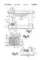
- FIG. 1is a side view of the lower portion of a plunge-type router incorporating the depth stop of the present invention
- FIG. 2is a cross-section of a first embodiment of the depth stop mechanism of the present invention, taken along line 2--2 in FIG. 1;
- FIG. 3is a cross-section of a portion of the plunge-type router of FIG. 1, taken along line 3--3;
- FIG. 4is a perspective view of a second embodiment of the plunge router depth stop mechanism of the present invention.
- FIG. 5is an exploded view of the depth stop mechanism of FIG. 4.
- FIG. 6is a cross-section of the depth stop mechanism of FIG. 4, taken along line 6--6.
- a plunge router 10which includes a motor housing 12 mounted on two column shafts 14 extending from a base 16.
- the motor housing 12is mounted on the columns 14 so as to permit the housing 12 to be raised and lowered with respect to the base 16 as shown by the arrows.
- the travel of the motor housing 12 toward the base 16is limited by a depth stop assembly 18, in that, the motor housing 12 will be prevented from travelling further when the adjustable stop ram 20 of the motor housing 12 abuts the top surface 22 of the depth stop assembly 18.
- the stop assembly 18includes a screw stud 24 pressed into a knob 26 to prevent relative rotation.
- Screw stud 24is threaded to match the internal threads on an inner wall 28 of the boss 30 and is threadably mounted within it.
- the screw stud 24 thread pitchis 1/16 inch for this embodiment, although different thread pitches will also work.
- the boss 30is molded or machined as part of the router base 16.
- a spring 32is disposed around the inner wall 28 of the boss 30.
- a scale sleeve 34surrounds the spring 32 and, when assembled, compresses the spring 32.
- An outer wall 36 of the boss 30is generally concentric with the scale sleeve 34, and is sized to provide a small gap therebetween which allows the scale sleeve 34 to slide freely up and down (i.e. axially) within the outer wall 36.
- the scale sleeve 34is preferably formed from a plastic material and has a cylindrical wall 38 molded to an annular top 40.
- the scale sleeve 34includes a key 35 which protrudes from a portion of cylindrical wall 38 and extends into a complimentary notch in boss 30 in a known manner. This arrangement permits the scale sleeve 34 to slide axially within the bore 30, but prevents the scale sleeve from rotating with respect to the bore.
- the scale sleeve 34is shown to be cylindrical, it could be of a different shape.
- the scale sleeve 34could be formed from a material other than plastic. As best shown in FIG.
- the annular top 40includes an aperture 42 having a diameter that is just large enough for the screw stud 24 to easily slide therethrough.
- a cylindrical lip 44Around the periphery on the underside of aperture 42 is a cylindrical lip 44 which helps to retain the spring 32 beneath the annular top 40.
- a printed scale 46(FIG. 1) approximately one-half inch long, preferably having indicia identifying depth-of-cut increments of 1/16 inch.
- the height of the outer wall 36 of the boss 30is sufficient to retain the scale sleeve 34 throughout its length of travel.
- an opening 56is cut into the outer wall 36 at a depth such that the depth-of-cut indication on the printed scale 46 will line up with the bottom of the opening 56 on the outer wall 36 for the corresponding depth-of-cut of the router 10. This arrangement allows for accurate visual adjustment down to increments of 1/16 inch.
- Knob 26 of stop assembly 18is of a generally cylindrical shape.
- the outer surface of the upper portion 48 of the knob 26is preferably knurled to give the operator a better grip when turning the stop assembly 18 to adjust the depth-of-cut.
- the lower portion of the cylindrical side 48 of the knob 26has four generally V-shaped notches 50 cut into it, spaced approximately 90° apart, with the notches being oriented in the vertical direction. As shown in FIG. 2, these notches 50 engage a tab 52 mounted to or molded as part of key 35 of the scale sleeve 34.
- the tab 52is shaped to include a small flexible finger 54 which rests against the lower portion of the knob 26 and audibly snaps into engagement with a V-shaped notch when so aligned.
- a small flexible finger 54which rests against the lower portion of the knob 26 and audibly snaps into engagement with a V-shaped notch when so aligned.
- This printed scale 46can thus be used visually by the router operator to set the depth-of-cut to the nearest 1/16 inch increment. The router operator may then, if he requires more accuracy, continue rotating the stop assembly 18 and listen for a snapping sound made as the finger 54 engages one of the notches 50. Each snap, which occurs every quarter turn, will thus represent 1/64 inch difference in depth-of-cut, thereby giving the operator greater accuracy than with the visual scale alone.
- a stop assembly 80is comprised of a threaded screw member 82 pressed into or molded to a knob 84 to prevent relative rotation.
- the threaded screw member 82is threaded to match internal threads on an inner wall 86 of a boss 88 and is threadably mounted therewithin.
- Threaded screw member 82has a thread pitch of about 1/16 inch pitch for this particular embodiment, although other pitches could be used.
- the boss 88is machined or molded into the router base 90.
- a scale sleeve 92Positioned around the inner wall 86 of boss 88 and encircling the threaded screw member 82 is a scale sleeve 92.
- Outer wall 94 of boss 88is generally concentric with scale sleeve 92, with a small gap therebetween them to allow scale sleeve 92 to freely slide up and down (i.e. axially) within outer wall 94.
- Scale sleeve 92is made of plastic and is generally cylindrical in shape. Molded into scale sleeve 92 are two retaining lips 96 which protrude radially inward from the inner cylindrical surface 98 near the top end 100 of the scale sleeve 92. As best shown in FIG. 6, retaining lips 96 are generally triangular shaped. Adjacent to either side of a retaining lip 96 are slots 102 cut through cylindrical side 104 of scale sleeve 92. Slots 102 begin at top end 100 and extend about half way down cylindrical side 104, thereby forming flexible sleeves around retaining lips 96. This arrangement allows for some flexing around lips 96 when the depth stop is being assembled.
- a semi-spherical projection 106is molded into the scale sleeve 92.
- Projection 106is located on the inner cylindrical surface 98 half way between the pair of retaining lips 96, a small distance down from top end 100.
- This projection 106is also located adjacent to and between two slots 108, similar to the slots around retaining lips 96, in order to allow projection 106 to flex during operation of the depth stop.
- Scale sleeve 92includes a key 111 which protrudes radially outward from the outer cylindrical surface 110.
- the key 111is opposite the projection 106 and includes a printed scale 112 approximately one-half inch long, having increments down to 1/16 inch, imprinted thereon.
- An opening 114is cut into outer wall 94 of boss 88 and is sized to receive key 111.
- the opening 114has a depth such that the depth-of-cut indication on printed scale 112 will line up with the bottom of opening 114 on outer wall 94 for the proper depth-of-cut of the router.
- This scaleallows for visual adjustment down to increments of 1/16 inch in depth-of-cut.
- a small projection 126is molded into cylindrical side 104 of scale sleeve 92 near the bottom of scale sleeve 92. This projection 126 engages a small ledge (not shown) within boss 88 to insure that scale sleeve 92 does not become disengaged from boss 88 inadvertently.
- Knob 84 of stop assembly 80is generally cylindrical in shape. Upper portion 118 of knob 84 has a larger diameter than the diameter of inner cylindrical surface 98 of scale sleeve 92 sufficient to cover top end 100 of scale sleeve 92. Lower portion 120 of the knob has a diameter that is slightly smaller than the inner cylindrical surface 98 of scale sleeve 92, yet large enough to hold retaining lips 96 when stop assembly 80 is assembled into scale sleeve 92. Slots 102, which allow for lips 96 to flex, allow for ease of assembly. Upper portion 118 and lower portion 120 of knob 84 are spaced apart a small distance to allow for neck 122 to be formed in between.
- Neck 122is shaped in order to allow retaining lips 96 to nest therewithin when stop assembly 80 is assembled into scale sleeve 92. This configuration, then, will cause scale sleeve 92 to be retained by neck 122 of stop assembly 80, holding top end 100 of scale sleeve 92 against the upper portion 118 of knob 84, while still allowing knob 84 to rotate relative to scale sleeve 92.
- This second embodimentoperates similar to the first embodiment.
- threaded screw member 82is screwed into boss 88, simultaneously lowering scale sleeve 92 into boss 88, due to the engagement between retaining lips 96 of scale sleeve 92 and neck 122 of the knob 84.
- More of the printed scale 112is, therefore, covered by outer wall 94 of boss 88 indicating an increased depth-of-cut by the router.
- Each full revolution of the knobi.e. 360° preferably represents a 1/16 inch change in the depth-of-cut.
- Printed scale 112is thus used visually by the router operator to set the depth-of-cut to the nearest 1/16 inch. The router operator may then, if he requires more accuracy, continue rotating the stop assembly 80 and listen for the snapping sound made as the projection 106 engages one of the detents 124. Each snap, which occurs every quarter turn, represents 1/64 inch difference in depth-of-cut, thereby giving the operator greater accuracy than with the visual scale alone.
- the thread pitchcould be varied for a different depth-of-cut adjustment each rotation, or the number of notches usually positioned equiangularly, could be varied, further increasing or decreasing the precision with which changes in depth-of-cut are made.
Landscapes
- Engineering & Computer Science (AREA)
- Mechanical Engineering (AREA)
- Life Sciences & Earth Sciences (AREA)
- Wood Science & Technology (AREA)
- Forests & Forestry (AREA)
- Milling, Drilling, And Turning Of Wood (AREA)
Abstract
Description
Claims (12)
Priority Applications (3)
| Application Number | Priority Date | Filing Date | Title |
|---|---|---|---|
| US08/066,483US5320463A (en) | 1993-05-24 | 1993-05-24 | Depth stop for a plunge router |
| DE4417511ADE4417511A1 (en) | 1993-05-24 | 1994-05-19 | Milling depth limitation device for a router |
| JP6133661AJPH06335901A (en) | 1993-05-24 | 1994-05-24 | Plunge-type router |
Applications Claiming Priority (1)
| Application Number | Priority Date | Filing Date | Title |
|---|---|---|---|
| US08/066,483US5320463A (en) | 1993-05-24 | 1993-05-24 | Depth stop for a plunge router |
Publications (1)
| Publication Number | Publication Date |
|---|---|
| US5320463Atrue US5320463A (en) | 1994-06-14 |
Family
ID=22069782
Family Applications (1)
| Application Number | Title | Priority Date | Filing Date |
|---|---|---|---|
| US08/066,483Expired - LifetimeUS5320463A (en) | 1993-05-24 | 1993-05-24 | Depth stop for a plunge router |
Country Status (3)
| Country | Link |
|---|---|
| US (1) | US5320463A (en) |
| JP (1) | JPH06335901A (en) |
| DE (1) | DE4417511A1 (en) |
Cited By (15)
| Publication number | Priority date | Publication date | Assignee | Title |
|---|---|---|---|---|
| USD416460S (en) | 1998-11-16 | 1999-11-16 | Porter-Cable Corporation | Plunge router |
| US5988241A (en)* | 1998-11-16 | 1999-11-23 | Porter-Cable Corporation | Ergonomic router handles |
| US5998897A (en)* | 1998-11-16 | 1999-12-07 | Porter-Cable Corporation | Router chuck mounting system |
| US6065912A (en)* | 1998-11-16 | 2000-05-23 | Porter-Cable Corporation | Router switching system |
| US6079915A (en)* | 1998-11-16 | 2000-06-27 | Porter-Cable Corporation | Plunge router depth stop system |
| US6113323A (en)* | 1998-11-16 | 2000-09-05 | Porter-Cable Corporation | Plunge router sub-base alignment |
| US6139229A (en)* | 1998-11-16 | 2000-10-31 | Porter-Cable Corporation | Plunge router fine depth adjustment system |
| US6261036B1 (en) | 1998-11-16 | 2001-07-17 | Porter-Cable Corporation | Plunge router locking system |
| US6474378B1 (en) | 2001-05-07 | 2002-11-05 | S-B Power Tool Company | Plunge router having electronic depth adjustment |
| WO2003000473A1 (en)* | 2001-06-20 | 2003-01-03 | Black & Decker Inc | Apparatus for setting of a zero-reference point |
| US20050079025A1 (en)* | 2003-10-14 | 2005-04-14 | Credo Technology Corporation | Depth rod adjustment mechanism for a plunge-type router |
| US20080008551A1 (en)* | 2005-07-07 | 2008-01-10 | Black & Decker Inc. | Router |
| CN105856048A (en)* | 2016-06-13 | 2016-08-17 | 李培培 | Industrial equipment grinding machine |
| US11648704B2 (en) | 2021-06-10 | 2023-05-16 | Black & Decker Inc. | Power tool router |
| US12285881B2 (en) | 2019-05-15 | 2025-04-29 | Milwaukee Electric Tool Corporation | Offset base for router |
Families Citing this family (1)
| Publication number | Priority date | Publication date | Assignee | Title |
|---|---|---|---|---|
| DE102021131074A1 (en) | 2021-11-26 | 2023-06-01 | Jörg Fanta | Setting aid for a router |
Citations (13)
| Publication number | Priority date | Publication date | Assignee | Title |
|---|---|---|---|---|
| CA506073A (en)* | 1954-09-28 | F. Turnbull Roger | Portable track-guided tilt router | |
| US3897166A (en)* | 1971-12-29 | 1975-07-29 | Ralph D Adams | Drill feed control |
| US4566830A (en)* | 1983-04-21 | 1986-01-28 | Peter Maier | Router with quick depth of cut adjustment |
| US4652191A (en)* | 1986-02-04 | 1987-03-24 | Lucien Bernier | Press router |
| US4674548A (en)* | 1985-12-26 | 1987-06-23 | The Boeing Company | Adjustable router |
| US4770573A (en)* | 1986-10-15 | 1988-09-13 | Ryobi Ltd. | Cutting depth adjusting mechanism of a router |
| US4813822A (en)* | 1988-01-05 | 1989-03-21 | Dresser Industries, Inc. | Power drill system with adjustable depth sensing means |
| US4878644A (en)* | 1988-05-20 | 1989-11-07 | Charles Downing | Router bracket |
| US5078557A (en)* | 1991-02-28 | 1992-01-07 | Ryobi Motor Products Corp. | Limit stops for a router depth of cut adjustment mechanism |
| US5088865A (en)* | 1991-02-28 | 1992-02-18 | Ryobi Motor Products Corp. | Depth of cut adjustment mechansm for a router |
| US5143494A (en)* | 1991-10-18 | 1992-09-01 | Ryobi Motor Products Corp. | Depth of cut lock mechanism for a plunge type router |
| US5191921A (en)* | 1991-10-18 | 1993-03-09 | Ryobi Motor Products Corp. | Adjustable depth of cut stop mechanism for a plunge type router |
| US5207253A (en)* | 1992-03-20 | 1993-05-04 | Ryobi Motor Products, Corp | Plunge router |
- 1993
- 1993-05-24USUS08/066,483patent/US5320463A/ennot_activeExpired - Lifetime
- 1994
- 1994-05-19DEDE4417511Apatent/DE4417511A1/ennot_activeWithdrawn
- 1994-05-24JPJP6133661Apatent/JPH06335901A/enactivePending
Patent Citations (13)
| Publication number | Priority date | Publication date | Assignee | Title |
|---|---|---|---|---|
| CA506073A (en)* | 1954-09-28 | F. Turnbull Roger | Portable track-guided tilt router | |
| US3897166A (en)* | 1971-12-29 | 1975-07-29 | Ralph D Adams | Drill feed control |
| US4566830A (en)* | 1983-04-21 | 1986-01-28 | Peter Maier | Router with quick depth of cut adjustment |
| US4674548A (en)* | 1985-12-26 | 1987-06-23 | The Boeing Company | Adjustable router |
| US4652191A (en)* | 1986-02-04 | 1987-03-24 | Lucien Bernier | Press router |
| US4770573A (en)* | 1986-10-15 | 1988-09-13 | Ryobi Ltd. | Cutting depth adjusting mechanism of a router |
| US4813822A (en)* | 1988-01-05 | 1989-03-21 | Dresser Industries, Inc. | Power drill system with adjustable depth sensing means |
| US4878644A (en)* | 1988-05-20 | 1989-11-07 | Charles Downing | Router bracket |
| US5078557A (en)* | 1991-02-28 | 1992-01-07 | Ryobi Motor Products Corp. | Limit stops for a router depth of cut adjustment mechanism |
| US5088865A (en)* | 1991-02-28 | 1992-02-18 | Ryobi Motor Products Corp. | Depth of cut adjustment mechansm for a router |
| US5143494A (en)* | 1991-10-18 | 1992-09-01 | Ryobi Motor Products Corp. | Depth of cut lock mechanism for a plunge type router |
| US5191921A (en)* | 1991-10-18 | 1993-03-09 | Ryobi Motor Products Corp. | Adjustable depth of cut stop mechanism for a plunge type router |
| US5207253A (en)* | 1992-03-20 | 1993-05-04 | Ryobi Motor Products, Corp | Plunge router |
Cited By (19)
| Publication number | Priority date | Publication date | Assignee | Title |
|---|---|---|---|---|
| USD416460S (en) | 1998-11-16 | 1999-11-16 | Porter-Cable Corporation | Plunge router |
| US5988241A (en)* | 1998-11-16 | 1999-11-23 | Porter-Cable Corporation | Ergonomic router handles |
| US5998897A (en)* | 1998-11-16 | 1999-12-07 | Porter-Cable Corporation | Router chuck mounting system |
| US6065912A (en)* | 1998-11-16 | 2000-05-23 | Porter-Cable Corporation | Router switching system |
| US6079915A (en)* | 1998-11-16 | 2000-06-27 | Porter-Cable Corporation | Plunge router depth stop system |
| US6113323A (en)* | 1998-11-16 | 2000-09-05 | Porter-Cable Corporation | Plunge router sub-base alignment |
| US6139229A (en)* | 1998-11-16 | 2000-10-31 | Porter-Cable Corporation | Plunge router fine depth adjustment system |
| US6261036B1 (en) | 1998-11-16 | 2001-07-17 | Porter-Cable Corporation | Plunge router locking system |
| US6474378B1 (en) | 2001-05-07 | 2002-11-05 | S-B Power Tool Company | Plunge router having electronic depth adjustment |
| WO2003000473A1 (en)* | 2001-06-20 | 2003-01-03 | Black & Decker Inc | Apparatus for setting of a zero-reference point |
| US20050079025A1 (en)* | 2003-10-14 | 2005-04-14 | Credo Technology Corporation | Depth rod adjustment mechanism for a plunge-type router |
| US6896451B2 (en)* | 2003-10-14 | 2005-05-24 | Credo Technology Corporation | Depth rod adjustment mechanism for a plunge-type router |
| US20080008551A1 (en)* | 2005-07-07 | 2008-01-10 | Black & Decker Inc. | Router |
| US7484915B2 (en) | 2005-07-07 | 2009-02-03 | Black & Decker Inc. | Router |
| US20090114314A1 (en)* | 2005-07-07 | 2009-05-07 | Black & Decker Inc. | Router |
| US8146629B2 (en) | 2005-07-07 | 2012-04-03 | Black & Decker, Inc. | Router |
| CN105856048A (en)* | 2016-06-13 | 2016-08-17 | 李培培 | Industrial equipment grinding machine |
| US12285881B2 (en) | 2019-05-15 | 2025-04-29 | Milwaukee Electric Tool Corporation | Offset base for router |
| US11648704B2 (en) | 2021-06-10 | 2023-05-16 | Black & Decker Inc. | Power tool router |
Also Published As
| Publication number | Publication date |
|---|---|
| JPH06335901A (en) | 1994-12-06 |
| DE4417511A1 (en) | 1994-12-01 |
Similar Documents
| Publication | Publication Date | Title |
|---|---|---|
| US5320463A (en) | Depth stop for a plunge router | |
| US5862715A (en) | Tactile detent knob | |
| US4787794A (en) | Drill press with quick adjusting stop nut assembly | |
| US4048897A (en) | Laterally engagable and releasable nut assembly | |
| US5613813A (en) | Router adjustment ring | |
| EP0052994A2 (en) | Improvements in or relating to setting mechanisms especially for tools for carrying out routing and like operations | |
| JPS6235041B2 (en) | ||
| US10691158B2 (en) | Locking knob | |
| JPH0584704A (en) | Rooter with cut groove depth adjustment mecaanism | |
| US4335768A (en) | Depth of cut adjustment mechanism | |
| US4528755A (en) | Dial gauge | |
| US2658395A (en) | Differential knob device | |
| US4262419A (en) | Hand-held cutter for cutting mounting board and the like | |
| US7685719B2 (en) | Circle cutting device | |
| US3061869A (en) | Control knobs | |
| US2480914A (en) | Protractor | |
| GB2213750A (en) | Chamfering machine | |
| US20080152450A1 (en) | Router | |
| US5276975A (en) | Audible-visual edge finder | |
| US4920656A (en) | Compass assembly with dial biasing disk | |
| US6025588A (en) | Optical analog potentiometer | |
| US4339877A (en) | Hand-held cutter for cutting mounting board and the like | |
| EP0410058B1 (en) | Machine and method for cutting oval shapes | |
| EP3227073B1 (en) | Portable power tool with a depth adjustment mechanism | |
| US4875512A (en) | Feeder having a speed change mechanism with a graduated threaded-shaft protector |
Legal Events
| Date | Code | Title | Description |
|---|---|---|---|
| AS | Assignment | Owner name:RYOBI MOTOR PRODUCTS CORP., SOUTH CAROLINA Free format text:ASSIGNMENT OF ASSIGNORS INTEREST;ASSIGNORS:MCCURRY, RONALD C.;MCCRACKEN, ROBERT;CHILDS, DALE E.;REEL/FRAME:006574/0252 Effective date:19930520 | |
| STPP | Information on status: patent application and granting procedure in general | Free format text:APPLICATION UNDERGOING PREEXAM PROCESSING | |
| FPAY | Fee payment | Year of fee payment:4 | |
| AS | Assignment | Owner name:RYOBI NORTH AMERICA, INC., SOUTH CAROLINA Free format text:ASSIGNMENT OF ASSIGNORS INTEREST;ASSIGNOR:RYOBI MOTOR PRODUCTS CORPORATION;REEL/FRAME:009764/0780 Effective date:19990222 | |
| AS | Assignment | Owner name:HSBC BANK USA, NEW YORK Free format text:SECURITY INTEREST;ASSIGNORS:ONE WORLD TECHNOLOGIES INC.;RYOBI TECHNOLOGIES, INC.;OWT INDUSTRIES, INC.;REEL/FRAME:011103/0770 Effective date:20000801 | |
| AS | Assignment | Owner name:ONE WORLD TECHNOLOGIES, INC., SOUTH CAROLINA Free format text:ASSIGNMENT OF ASSIGNORS INTEREST;ASSIGNOR:RYOBI NORTH AMERICA, INC.;REEL/FRAME:011149/0407 Effective date:20000731 | |
| REMI | Maintenance fee reminder mailed | ||
| FPAY | Fee payment | Year of fee payment:8 | |
| SULP | Surcharge for late payment | Year of fee payment:7 | |
| AS | Assignment | Owner name:ONE WORLD TECHNOLOGIES LIMITED, BERMUDA Free format text:ASSIGNMENT OF ASSIGNORS INTEREST;ASSIGNOR:ONE WORLD TECHNOLOGIES, INC.;REEL/FRAME:014066/0731 Effective date:20030512 | |
| FPAY | Fee payment | Year of fee payment:12 | |
| FEPP | Fee payment procedure | Free format text:PAYOR NUMBER ASSIGNED (ORIGINAL EVENT CODE: ASPN); ENTITY STATUS OF PATENT OWNER: LARGE ENTITY Free format text:PAYER NUMBER DE-ASSIGNED (ORIGINAL EVENT CODE: RMPN); ENTITY STATUS OF PATENT OWNER: LARGE ENTITY |