US5319943A - Frost/defrost control system for heat pump - Google Patents
Frost/defrost control system for heat pumpDownload PDFInfo
- Publication number
- US5319943A US5319943AUS08/008,765US876593AUS5319943AUS 5319943 AUS5319943 AUS 5319943AUS 876593 AUS876593 AUS 876593AUS 5319943 AUS5319943 AUS 5319943A
- Authority
- US
- United States
- Prior art keywords
- outdoor
- temperature
- frost
- coil
- expansion valve
- Prior art date
- Legal status (The legal status is an assumption and is not a legal conclusion. Google has not performed a legal analysis and makes no representation as to the accuracy of the status listed.)
- Expired - Fee Related
Links
- 238000009825accumulationMethods0.000claimsabstractdescription26
- 230000000977initiatory effectEffects0.000claimsabstractdescription13
- 238000012544monitoring processMethods0.000claimsabstractdescription10
- 230000002349favourable effectEffects0.000claimsabstractdescription5
- 238000005086pumpingMethods0.000claimsabstract15
- 239000003507refrigerantSubstances0.000claimsdescription27
- 238000000034methodMethods0.000claimsdescription24
- 239000003570airSubstances0.000claimsdescription21
- 239000012080ambient airSubstances0.000claimsdescription18
- 238000001816coolingMethods0.000claimsdescription15
- 230000008859changeEffects0.000claimsdescription10
- 238000004378air conditioningMethods0.000claimsdescription7
- 238000011217control strategyMethods0.000claimsdescription7
- 238000011084recoveryMethods0.000claimsdescription3
- 238000012360testing methodMethods0.000claimsdescription3
- 239000012530fluidSubstances0.000claims9
- 230000003247decreasing effectEffects0.000claims1
- 238000010438heat treatmentMethods0.000description28
- 238000004891communicationMethods0.000description22
- 230000006870functionEffects0.000description19
- 238000005057refrigerationMethods0.000description12
- 230000000694effectsEffects0.000description6
- 238000000253optical time-domain reflectometryMethods0.000description6
- 238000012546transferMethods0.000description6
- 230000001276controlling effectEffects0.000description5
- 238000010586diagramMethods0.000description4
- 230000007257malfunctionEffects0.000description4
- 238000001514detection methodMethods0.000description3
- 238000001704evaporationMethods0.000description3
- 230000008020evaporationEffects0.000description3
- 239000007791liquid phaseSubstances0.000description3
- 230000008569processEffects0.000description3
- 238000010257thawingMethods0.000description3
- 230000003044adaptive effectEffects0.000description2
- 230000008901benefitEffects0.000description2
- 230000006872improvementEffects0.000description2
- 238000012886linear functionMethods0.000description2
- 239000007788liquidSubstances0.000description2
- 239000000203mixtureSubstances0.000description2
- 230000009467reductionEffects0.000description2
- 230000001105regulatory effectEffects0.000description2
- ZAKOWWREFLAJOT-CEFNRUSXSA-ND-alpha-tocopherylacetateChemical compoundCC(=O)OC1=C(C)C(C)=C2O[C@@](CCC[C@H](C)CCC[C@H](C)CCCC(C)C)(C)CCC2=C1CZAKOWWREFLAJOT-CEFNRUSXSA-N0.000description1
- 208000009989Posterior Leukoencephalopathy SyndromeDiseases0.000description1
- 101150108015STR6 geneProteins0.000description1
- 101100386054Saccharomyces cerevisiae (strain ATCC 204508 / S288c) CYS3 geneProteins0.000description1
- 230000003213activating effectEffects0.000description1
- 238000009529body temperature measurementMethods0.000description1
- 238000004364calculation methodMethods0.000description1
- 230000000295complement effectEffects0.000description1
- 230000001351cycling effectEffects0.000description1
- 238000013480data collectionMethods0.000description1
- 230000001627detrimental effectEffects0.000description1
- 239000000284extractSubstances0.000description1
- 238000005259measurementMethods0.000description1
- 238000012986modificationMethods0.000description1
- 230000004048modificationEffects0.000description1
- 230000000737periodic effectEffects0.000description1
- 230000001681protective effectEffects0.000description1
- 238000012552reviewMethods0.000description1
- 230000035939shockEffects0.000description1
- 101150035983str1 geneProteins0.000description1
Images


Classifications
- F—MECHANICAL ENGINEERING; LIGHTING; HEATING; WEAPONS; BLASTING
- F25—REFRIGERATION OR COOLING; COMBINED HEATING AND REFRIGERATION SYSTEMS; HEAT PUMP SYSTEMS; MANUFACTURE OR STORAGE OF ICE; LIQUEFACTION SOLIDIFICATION OF GASES
- F25D—REFRIGERATORS; COLD ROOMS; ICE-BOXES; COOLING OR FREEZING APPARATUS NOT OTHERWISE PROVIDED FOR
- F25D21/00—Defrosting; Preventing frosting; Removing condensed or defrost water
- F25D21/002—Defroster control
- F25D21/006—Defroster control with electronic control circuits
- F—MECHANICAL ENGINEERING; LIGHTING; HEATING; WEAPONS; BLASTING
- F24—HEATING; RANGES; VENTILATING
- F24F—AIR-CONDITIONING; AIR-HUMIDIFICATION; VENTILATION; USE OF AIR CURRENTS FOR SCREENING
- F24F1/00—Room units for air-conditioning, e.g. separate or self-contained units or units receiving primary air from a central station
- F24F1/0003—Room units for air-conditioning, e.g. separate or self-contained units or units receiving primary air from a central station characterised by a split arrangement, wherein parts of the air-conditioning system, e.g. evaporator and condenser, are in separately located units
- F—MECHANICAL ENGINEERING; LIGHTING; HEATING; WEAPONS; BLASTING
- F25—REFRIGERATION OR COOLING; COMBINED HEATING AND REFRIGERATION SYSTEMS; HEAT PUMP SYSTEMS; MANUFACTURE OR STORAGE OF ICE; LIQUEFACTION SOLIDIFICATION OF GASES
- F25B—REFRIGERATION MACHINES, PLANTS OR SYSTEMS; COMBINED HEATING AND REFRIGERATION SYSTEMS; HEAT PUMP SYSTEMS
- F25B47/00—Arrangements for preventing or removing deposits or corrosion, not provided for in another subclass
- F25B47/02—Defrosting cycles
- F25B47/022—Defrosting cycles hot gas defrosting
- F25B47/025—Defrosting cycles hot gas defrosting by reversing the cycle
- F—MECHANICAL ENGINEERING; LIGHTING; HEATING; WEAPONS; BLASTING
- F24—HEATING; RANGES; VENTILATING
- F24F—AIR-CONDITIONING; AIR-HUMIDIFICATION; VENTILATION; USE OF AIR CURRENTS FOR SCREENING
- F24F11/00—Control or safety arrangements
- F24F11/30—Control or safety arrangements for purposes related to the operation of the system, e.g. for safety or monitoring
- F24F11/41—Defrosting; Preventing freezing
- F—MECHANICAL ENGINEERING; LIGHTING; HEATING; WEAPONS; BLASTING
- F25—REFRIGERATION OR COOLING; COMBINED HEATING AND REFRIGERATION SYSTEMS; HEAT PUMP SYSTEMS; MANUFACTURE OR STORAGE OF ICE; LIQUEFACTION SOLIDIFICATION OF GASES
- F25B—REFRIGERATION MACHINES, PLANTS OR SYSTEMS; COMBINED HEATING AND REFRIGERATION SYSTEMS; HEAT PUMP SYSTEMS
- F25B2600/00—Control issues
- F25B2600/11—Fan speed control
- F25B2600/111—Fan speed control of condenser fans
- Y—GENERAL TAGGING OF NEW TECHNOLOGICAL DEVELOPMENTS; GENERAL TAGGING OF CROSS-SECTIONAL TECHNOLOGIES SPANNING OVER SEVERAL SECTIONS OF THE IPC; TECHNICAL SUBJECTS COVERED BY FORMER USPC CROSS-REFERENCE ART COLLECTIONS [XRACs] AND DIGESTS
- Y02—TECHNOLOGIES OR APPLICATIONS FOR MITIGATION OR ADAPTATION AGAINST CLIMATE CHANGE
- Y02B—CLIMATE CHANGE MITIGATION TECHNOLOGIES RELATED TO BUILDINGS, e.g. HOUSING, HOUSE APPLIANCES OR RELATED END-USER APPLICATIONS
- Y02B30/00—Energy efficient heating, ventilation or air conditioning [HVAC]
- Y02B30/70—Efficient control or regulation technologies, e.g. for control of refrigerant flow, motor or heating
Definitions
- the present inventionrelates generally to electronic control systems for air conditioners, heat pumps and refrigeration equipment. More particularly, the invention relates to an apparatus and method utilizing digital circuitry to control a heat pump during its normal operating cycle in order to control the accumulation of frost on the outdoor evaporator coil while providing optimum system efficiency and performance during the defrost cycle.
- the basic refrigeration cycleoperates by metering refrigerant through a closed system in a precisely controlled manner.
- the refrigerantcools by evaporation in a heat exchanger commonly called an evaporator coil.
- the refrigerantis metered to the evaporator coil through an orifice sometimes called an expansion valve.
- a refrigeration systemshould meter just enough refrigerant into the evaporator coil so that the refrigerant extracts heat throughout the length of the coil as it evaporates. Due to changing dynamics of the system, changes in thermostat settings and changes in load from sun, wind and so forth, the optimal flow through the expansion valve will need to be varied as the system operates.
- the present inventionaddresses this need through the use of a microprocessor-based control system and digitally controllable expansion valve.
- the present systemutilizes a "demand defrost" scheme wherein the intervals between defrost cycles vary rather than being simply performed on a periodic basis.
- the defrost cycleis initiated only when a predetermined amount of frost has accumulated on the evaporator coil. This saves energy and improves efficiency by eliminating unnecessary defrost cycles.
- time intervals between defrost cyclesare further maximized by making the outdoor coil conditions less favorable to a frost buildup. This is accomplished by monitoring the rate of accumulation of frost buildup in terms of the temperature difference between the ambient air and outdoor coil. If a change in the slope of this temperature difference is sensed, refrigerant flow through the system is increased by modulating the expansion valve setting, thereby raising the outdoor coil temperature.
- the microprocessor-based systemdetermines the proper valve setting, balancing the objective of maintaining an efficient temperature coil with the objective of gradually raising the temperature of the coil (with some efficiency tradeoff) to retard frost accumulation. The system is therefore able to maintain a level of efficient operation for longer periods.
- the present control systemalso modulates the expansion valve setting to open the valve orifice to a greater diameter than normal on the initiation of the defrost cycle. This enables rapid transfer of the refrigerant charge to the outdoor coil and significantly reduces the length of the defrost cycle. In addition, by pre-starting the outdoor fan prior to termination of the defrost cycle, pressure transients are reduced resulting in greater reliability and longevity of the heat pump and its components.
- FIG. 1is a schematic representation of the basic refrigeration cycle
- FIG. 2is a schematic diagram of a preferred embodiment of the refrigeration control system of the invention, illustrated in a heat pump application;
- FIG. 3is a schematic diagram of the control system of the present invention.
- FIGS. 4 and 5are detailed schematics illustrating the communication between the various microprocessors
- FIG. 6is a schematic representation illustrating the sensor arrangement utilized by the invention.
- FIG. 7is a cross-sectional view showing a preferred manner of positioning the ambient outdoor temperature sensor of the invention to reduce the effects of radiant heating;
- FIGS. 8A and 8B(also herein referred collectively to as FIG. 8) is a flowchart illustrating the implementation of the improved defrost cycle of the present invention
- FIG. 9is a graph depicting the performance improvement gained by pre-starting the outdoor fan prior to the termination of the defrost cycle
- FIG. 10is a graph illustrating the performance improvement gained by employing the expansion valve control strategy
- FIGS. 11A and 11B(also herein referred collectively to as FIG. 11) is a flowchart illustrating the control strategy employed by the present invention to monitor and reduce frost buildup on the outdoor coil;
- FIG. 12is a graph depicting air and outdoor coil temperature difference as a function of time
- FIG. 13is a software block diagram illustrating the preferred microprocessor-based control system
- FIG. 14A and 14B(also herein referred collectively to as FIG. 14) is a graph showing indoor coil temperature different over time for two different expansion valve control strategies.
- FIG. 14Adepicting a comparatively longer defrost and
- FIG. 14Bdepicting a comparatively shorter defrost;
- FIG. 15is a graph showing the optimum defrost initiation temperature for different outdoor ambient temperatures.
- the present inventionprovides an apparatus and method for optimizing the refrigeration cycle employed in air conditioners, heat pumps and refrigeration equipment.
- the systememploys a microprocessor based control system and a unique complement of sensors and an electronically controlled expansion valve.
- a heat pump systemcapable of providing both heating and cooling will be described.
- a heat pump system of the type describedmight be suitable for heating and cooling a commercial or residential building, although the principles of the invention are not limited to commercial and residential heating and cooling and are applicable to all pumped heat transfer systems.
- the heat pump cycleuses the cooling effect of evaporation to lower the temperature of the surroundings near one heat exchanger (the evaporator) and it uses the heating effect of high pressure, high temperature gas to raise the temperature of the surroundings hear another heat exchanger (the condenser). This is accomplished by releasing a refrigerant under pressure (usually in the liquid phase) into a low pressure region to cause the refrigerant to expand into a low temperature mixture of gas and liquid.
- this low pressure regioncomprises an evaporator coil, such as evaporator coil 10.
- the refrigerant mixtureonce in the evaporator coil 10 is exposed to the high temperature ambient air of the region desired to be cooled. Evaporation of refrigerant from liquid to gas absorbs heat from the ambient air and thereby cools it.
- refrigerant into the low pressure evaporator coilis usually metered by a restricted orifice or valve commonly called an expansion valve 12.
- a restricted orifice or valvecommonly called an expansion valve 12.
- expansion devicesThere are a wide variety of different types of expansion devices in use today, ranging from simple nonadjustable capillary tubes to electrically adjustable valves such as pulse width modulated valves.
- the refrigerant at the outlet of the evaporator coilis compressed back into a high pressure state by compressor 14 and condensed into a liquid phase by condenser 16 to be used once again.
- the condensing of high pressure gas into a liquid phasesupplies heat to the surroundings.
- FIG. 2wherein a heat pump system is depicted generally at 20.
- the systemincludes an indoor unit 22, a room unit or thermostat unit 23 and an outdoor unit 24.
- the indoor unitincludes an indoor coil or heat exchanger 26 and an indoor fan 28.
- the indoor fanis preferably driven by a variable speed motor 30.
- the indoor fan and coilare situated using suitable duct work so that the fan forces ambient indoor air across the indoor coil at a rate determined by the speed of the variable speed motor.
- the outdoor unitincludes an outdoor coil or heat exchanger 32 and an outdoor fan 34 driven by suitable motor 36.
- this outdoor coilfunctions as the evaporator and it is on outdoor coil 32 that frost typically builds when the temperature thereof falls below 32° F.
- the outdoor unitcomprises a protective housing which encases the outdoor coil and outdoor fan so that the fan will draw ambient outdoor air across the outdoor coil to improve heat transfer.
- the outdoor unitalso typically houses a compressor 38.
- the system illustrated in FIG. 2is a so-called "heat pump” system because it can be used for both cooling and heating, by simply reversing the function of the indoor coil and the outdoor coil. This is done with a four-way reversing valve 40.
- the four-way valvewhen the four-way valve is switched to the COOLING position (shown), the indoor coil functions as the evaporator and the outdoor coil functions as the condenser.
- the HEATING positionthe alternate position
- the indoor coilfunctions as the condenser coil and the outdoor coil functions as the evaporator coil.
- the present systemalso uses an electronically controllable expansion valve (EXV) 42.
- EXVelectronically controllable expansion valve
- the expansion valveis a continuously variable (or incrementally variable) stepper motor valve which can be adjusted electronically to a wide range of orifice sizes or valve openings, ranging from fully open to fully closed.
- pulse width modulated valvesbeing an example
- the present embodimentprefers the stepper motor valve because it provides ripple-free operation and because it is more trouble-free.
- the stepper motor valveonly needs to move or cycle when an orifice size adjustment is made. This may happen several times during a typical operating sequence (e.g., several times per hour). In contrast, the pulse width modulated valve cycles continuously during the entire operating sequence.
- the presently preferred system for controlling frost accumulation on the outdoor evaporator coilis a microprocessor-based system which gathers data from various sensors and which, among other things, determines the proper setting of the expansion valve based on the data gathered. More specifically, the presently preferred embodiment utilizes three interconnected microprocessor-based control units 44, 45 and 46. Control unit 44 is associated with the outdoor unit 24 and control unit 46 is associated with the indoor unit 22. In addition, the room unit or thermostat unit 23 may also include a microprocessor-based control unit 45. Preferably, all three microprocessor-based control units are linked together via a suitable communication link 48 such as a parallel or serial communication link.
- the outdoor control unit 44is in part responsible for data collection while the indoor control unit 46 is responsible for: on/off cycling of system, modulating the indoor fan speed, control of expansion valve, start/termination of demand defrost, malfunction detection and performing system diagnostic functions.
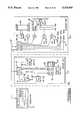
- the microprocessor-based control system used in implementing the refrigeration system of FIG. 2is shown substantially in FIG. 3.
- the indoor unit 22, room unit or thermostat unit 23 and outdoor unit 24are interconnected by communication link 48.
- communication link 48is a four wire bus supplying AC power and ground to all three units and also providing a pair of serial communication data lines.
- the indoor unit 22, room unit 23 and outdoor unit 24each have a microprocessor-based control unit which communicates with the other units over the communication link.
- the microprocessor-based control units 44 and 46have thus been illustrated.
- the room unit 23also includes a microprocessor-based control unit. The details have been omitted from FIG. 3 to simplify the illustration.
- the indoor fan or blower 28which includes an integrated drive and variable speed motor 30.
- the presently preferred embodimentuses a motor which requires 240 VAC.
- Control signals and logic signals sent via communication link 48are at 24 VAC and 5 VDC.
- a step-down transformer 180is provided on the indoor unit for this purpose.
- Motor 30receives its operating control instructions from and supplies status signals to the indoor control unit 46 at 24 VAC line levels over motor communication path 182.
- the presently preferred embodimentuses electric resistance heaters to supply auxiliary heat.
- Indoor control unit 46is responsible for determining when to turn the auxiliary heat on and off. This signal is supplied at 24 VAC logic levels. The indoor control unit 46 also supplies 24 VDC logic signals to control the expansion valve 42.
- the outdoor unitalso supplies and receives a number of different control signals at 24 VAC logic levels via the paths illustrated.
- outdoor control unit 44supplies the ON/OFF signal to compressor relay K1. This relay in turn energizes the compressor contactor 190.
- the outdoor control unit 44similarly supplies ON/OFF control signals to the heat/cool relay K2, which switches the reversing valve 40 as described above to place the system in either the HEATING or COOLING mode.
- the outdoor control unitsupplies logic signals to the fan ON/OFF relay K3 and the fan speed relay K4. These relays in turn control the outdoor fan motor 36.
- the outdoor fan motor 36is a two speed motor.
- Outdoor control unit 44also receives logic level data from the outdoor sensors, such as first temperature sensor 55, which measures the temperature of the outdoor coil, second temperature sensor 56, which measures the ambient or environment air temperature and discharge temperature sensor 54, which measures the discharge temperature of compressor.
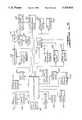
- the microprocessor-based control units 44, 45 and 46are shown in somewhat greater detail to show the types of signals which are communicated between the units during operation.
- the room unit control unit 45is shown together with its associated keypad 192 and display 194.
- the keypadis coupled to the room unit control unit 45 via an eight line parallel data bus.
- the displayis similarly coupled via a 36 line parallel data bus.
- the indoor temperature sensor 60 and indoor humidity sensor 62are also coupled to the room unit control unit 45.
- a humidity sensor 196may also be employed in the outdoor unit (see FIG. 5) so that outdoor humidity can be measured.
- a pressure cutout 198 and a temperature cutout 200are provided.
- FIG. 13is a software block diagram illustrating the functional software elements which comprise the present control system. Because the indoor control unit functions as the master in the presently preferred embodiment, many of the software modules of FIG. 13 reside in and are performed by the indoor control unit 46. Of course, from a system standpoint, any one of the microprocessor-based modules could serve as the master. In addition, the software functions depicted in FIG. 13 could be distributed across or shared by all three control units. Thus the specific allocation of certain functions to certain ones of the control units adopted by the present embodiment should not be viewed as a limitation upon the scope of the claims.
- the mainline control block 202This block or module interfaces, either directly or indirectly, with each of the remaining blocks or modules.
- the mainline block 202is supervised by the main control system block 201, which supplies the global system performance requirements.
- the mainline control blockis responsible for effectuating the instructions of the main control system by interfacing with the other modules. For example, the power up initialization and power up diagnostics blocks are called by the mainline control block during initial power up.
- the mainline control blockhas access to a math routines block 208 which is called upon anytime math calculations take place.
- mainline control block 202has access to the clock support and triac drive block 210 and the timer update/miscellaneous control block 212, which are used anywhere timing of events is involved.
- the systemis adaptive, in that it is capable of continuously updating parameters during normal operation. At initial power up, however, the system uses preset starting parameters which are stored in a nonvolatile RAM or NOVRAM memory that is accessed via the NOVRAM control/interface block 214.
- the nonvolatile RAMmay also store other numerical values such as constants which are not ordinarily altered during system operation.
- the use of nonvolatile RAM for this purposeis quite advantageous, since it allows a standardized hardware system to be custom programmed in the factory before shipment. This allows a more or less standard control module package to be used for a wide range of different heating and cooling systems by simple in factory programming. This results in a considerable cost savings.
- Communications and message handlingis provided by the communications block 216 and the control support messages block 218. These blocks implement the communication protocol described in Tables I-III. The actual details regarding the manner in which messages are placed on the communication link are handled by the bus block 220.
- System diagnosticsare performed by block 222. If desired, the system may be programmed to perform self-tests and self-configuration. This is performed by block 224.
- any miscellaneous support functionswhich do not fit the other described categories may be called by the mainline control block. For illustration purposes, the miscellaneous support block 226 is thus shown.
- Mainline control block 202is further responsible for the important functions of controlling the refrigeration system components, the indoor fan and any auxiliary heating equipment.
- an electronic expansion valve control block 228is provided. This block is responsible for determining and effecting the setting of the expansion valve.
- the compressor control block 230is provided for turning the compressor on and off via relay K1.
- a PID algorithm or other suitable control algorithm implemented in block 232provides the adaptive control by which the system updates its parameters during operation.
- the blower control block 234receives instructions from blower feedback detection block 236, pulse width modulation output control block 238 and blower ON/OFF delay block 240.
- the presently preferred indoor fan motoris driven by a pulse width modulation system by which the pulse width of the motor drive signal is varied to modulate the speed.
- the pulse width modulation output control bloc 238 and blower feedback detection block 236provide the pulse width modulated closed-loop system function.
- the blower ON/OFF delay block 240alters the ON/OFF sequence of the indoor fan to optimize airflow in relation to the temperature of the heat exchanging elements.
- the strip heat control block 242 and stage control block 244are provided.
- the strip heat control blockis responsible essentially for activating one or more relays to turn on the auxiliary heating elements.
- the stage control blockcauses the strip heat control block to do so in stages based on the desired temperature and how much heat is required.
- the presently preferred embodimentuses a demand defrost cycle to periodically melt accumulated frost on the coil. This is handled by the defrost control block 246.
- This block 246is described in more detail in the flowcharts on FIGS. 8 and 11. Interface between the defrost control block 246 and the outdoor unit 24 takes place through the mainline control block 202, the communications block 216 and the bus block 220.
- fan speedmay be regulated to control humidity or to maintain system operation within the ASHRAE comfort zone. This is handled by the humidity control block 248.
- serial communication link 48It is the nature of serial communication that the communication line is shared by all units and thus only one message is communicated at a time.
- the itemized data flow between room unit control unit 45 and indoor control unit 46 and between outdoor control unit 44 and indoor control unit 46are shown to illustrate the type of information which is passed back and forth during system operation. Although this transfer of data is illustrated as a parallel operation, and it could be implemented in a parallel communication link, the present embodiment prefers a serial link.
- the microprocessor-based systemssend and acknowledge messages in a serial fashion according to a predefined protocol.
- Each of the three unitshas sufficient random access memory, and in some cases nonvolatile memory, in which to store the various parameters which comprise the information communicated between them.
- the outdoor temperature measured by sensor 56is stored in the random access memory of outdoor control unit 44, to be thereafter communicated to indoor control unit 46 where it is stored in the random access memory of control unit 46. Thereafter, the same outdoor temperature data may be communicated to the room unit where it is stored in the room unit control unit's random access memory.
- each moduleis able to handle its own system critical tasks with high priority, attending to the noncritical tasks only when there is time.
- the building occupant requesting a display of outdoor temperaturewould not cause the outdoor module to neglect its task of controlling the compressor and likewise would not cause the indoor unit to neglect its task of regulating the fan speed.
- the building occupant requesting and outdoor temperature displaywould see a temperature value displayed instantly, although the value displayed would be the value obtained during the most recent data refresh sequence.
- temperature sensor 55is positioned within the refrigeration system 50, but temperature sensor 56 is positioned in the outside environment 52.
- temperature sensor 54measures the compressor discharge temperature used to control the expansion valve setting for steady state operation.
- Temperature sensor 55is preferably positioned adjacent to the outdoor coil 16 and accurately measures the temperature of the coil surface.
- Temperature sensor 56is preferably positioned in an airflow path which will measure the temperature of the ambient air surrounding or forced across the outdoor coil 16 Placement of this ambient air temperature sensor can be important. In the HEATING mode, with the evaporator coil located outdoors, the ambient temperature sensor should be positioned so that it will not receive direct sunlight. This may be accomplished by placing the ambient temperature sensor in a tube or enclosure which is open to airflow but shielded from the direct rays of the sun.
- FIG. 7illustrates one manner of shielding the ambient outdoor air temperature sensor 56.
- sensor 56is positioned within a tube 58 which is mounted in the housing sidewall of the outdoor unit 24.
- the tubeshields sensor 56 from the direct rays of the sun, as shown, but is open to the atmosphere and to the interior of the housing so that ambient air will flow across sensor 56 under force of outdoor fan 34.
- the moving airflow produced by fan 34virtually negates any radiant and conductive heating effects caused by heating of the housing by the sun's radiant energy. The result is an accurate measurement of the ambient air temperature which will be drawn by fan 34 across outdoor coil 32.
- Frost buildupcan be monitored and controlled using the control system of the present invention along with the temperature data provided by sensors 55 and 56.
- Microprocessors 44, 45 and 46preferably cooperate to receive data input by those sensors as well as thermostat 23 and other system components. These microprocessors also preferably cooperate as set forth above to provide control signals to the various other heat pump components including EXV 42, fans 28 and 34, four-way reversing valve 40 and so forth.
- the temperature measurements obtained from sensors 55 and 56, along with microprocessors 44, 45 and 46 according to the teachings of the present inventionfacilitate implementation of a demand defrost scheme which optimizes the time interval between the defrosting operations.
- the defrost cycleis initiated according to need, only when an optimal maximum amount of accumulation of frost has been built up on the evaporator coil.
- the sequence of steps performed by the control system of the present invention to provide this type of defrost systemis shown in detail in the flowchart of FIG. 8.
- step 100the difference between the outdoor air ambient temperature and the temperature of the outdoor coil, represented as ⁇ t , as measured by sensors 56 and 55, respectively, is calculated.
- the outdoor coil temperatureis then compared to a predetermined permitted level above which the defrost cycle will not be initiated, preferably about 32° F., in step 102.
- Temperature difference ⁇ tis then compared to a built-in difference indicative of an optimal maximum amount of frost necessary to initiate the defrost cycle.
- the built in differenceis preferably calculated based on a linear function of outdoor ambient air temperature.
- FIG. 15shows the relationship between the optimum defrost initiation temperature as a function of the outdoor air temperature.
- step 104is performed wherein the compressor discharge temperature control routine for heating operations is begun and the temperature monitoring process begins again at step 100.
- step 110the size of the current EXV 42 orifice, "Y" is recorded in memory for later use (step 110) and the defrost cycle of step 112 is initiated.
- the four-way valve 40is reversed and the outdoor fan 34 is shut off.
- the EXV 42is modulated by the control system to open the valve orifice to a maximum sized opening, that opening preferably being larger than the opening typically used in the cooling mode. By controlling this EXV opening such that it is larger than that typically used for normal cooling mode operations, rapid transfer of the refrigerant charge to the outdoor coil is achieved o the initiation of defrost.
- This defrost cycle or modeis continued until either a maximum amount of time has expired (such as 12 minutes), or until the outdoor coil 32 has reached a sufficiently high temperature to warrant defrost cycle termination (steps 114 and 116), preferably about 65° F.
- the elapsed timeis preferably kept by an internal clock in one of the microprocessors and the temperature is provided by sensor 55.
- steps 118 and 120are performed prior to terminating the defrost cycle in step 122.
- the controlsenses that the outdoor coil temperature has reached the preset built in defrost termination temperature, it turns on the outdoor fan in order to reduce pressure transients.
- the high pressure refrigerant in the outdoor heat exchangeris exposed to the low pressure suction line of the compressor and the low-pressure refrigerant line in the indoor heat exchanger is exposed to the high pressure discharge line of the compressor.
- a sudden rise and fall of pressureis experienced in the compressor discharge line.
- Such pressure transientssubject the compressor and the refrigerant lines to mechanical shock which are detrimental to the reliability and longevity of the heat pump.
- the present control systemBy starting the outdoor fan prior to the termination of the defrost cycle, the present control system allows the outdoor coil to be cooled and pressure transients to be reduced at defrost termination.
- the outdoor fanis turned on a predetermined amount of time prior to defrost termination, preferably for about twenty seconds. This substantially reduces pressure transients in the heating mode cycle. As shown by the graph of FIG. 9 wherein discharge pressure is plotted versus time, prestarting the outdoor fan prior to the termination of defrost reduces pressure transients in the system considerably.
- the defrost cycleis terminated in accordance with step 122.
- the four way valveis reversed and refrigerant gas again flows from the compressor to the condenser (indoor coil) to resume the heating operation.
- the EXV 42is left at its wide open position. This speeds the flow of refrigerant gas through the system in order to enhance the recovery of heating capacity. See FIG. 10 which shows in the shaded region the benefit gained by the improved strategy following termination of defrost.
- step 124the EXV opening is reduced.
- the EXV openingis reduced to an amount equal to Y+ ⁇ Y.
- step 128the compressor discharge temperature control routine of step 104 is performed wherein the control of the EXV 42 opening is based on the temperature of the compressor discharge.
- the control system of the present inventionenables the time between defrost cycles to be optimized.
- frostbuilds on the outdoor coil surfaces whenever the outdoor coil temperature is below 32° F. This reduces the heating capacity of the heat pump requiring a defrost for clearing the frost from the outdoor coil.
- the frost buildupcan be reduced by detecting its accumulation rate thereby allowing the heat pump to operate for a longer period before a defrost is needed.
- the controllermonitors the change in slope of the ⁇ t (refer to FIG. 12) and responds by raising the refrigerant flow by modulating the EXV, if it senses a change in the slope, thereby raising the outdoor coil temperature and making the outdoor coil conditions less favorable to a frost buildup.
- the control logic for reducing the frost accumulationis shown in FIG. 11. This strategy is not followed when it would cause excessive compressor flood back which could damage the compressor. Therefore the presently preferred embodiment is configured so compressor discharge is not allowed to fall below a preset level (e.g., 150° F.).
- steps 130-136ensure optimum heating mode operation based upon the compressor discharge temperature.
- steps 138-150are performed wherein the difference between the outdoor ambient air temperature and the outdoor coil temperature is calculated and monitored. If the rate of accumulation is increasing, as determined by steps 152-156, the frost reduction routine is performed unless the discharge temperature of the compressor is such that flooding of the compressor and reducing system reliability would result (steps 160-162).
- EXV 42is modulated so as to raise the refrigerant flow through the system and making the outdoor coil conditions less favorable to a frost buildup. Upon doing so, the system is returned to a control mode based on the temperature of the compressor discharge.
- the present inventionrepresents a significant departure from conventional defrost cycle control techniques which allows the system to be operated at higher efficiency than previously achieved.
- the time intervals between inefficient defrost operationsare maximized and defrost is performed more quickly.
Landscapes
- Engineering & Computer Science (AREA)
- Mechanical Engineering (AREA)
- General Engineering & Computer Science (AREA)
- Chemical & Material Sciences (AREA)
- Combustion & Propulsion (AREA)
- Physics & Mathematics (AREA)
- Thermal Sciences (AREA)
- Air Conditioning Control Device (AREA)
Abstract
Description
TABLE I ______________________________________ Room Control Unit Indoor Control Unit Outdoor Control Unit ______________________________________ ##STR1## ##STR2## ##STR3## REPEAT ______________________________________
TABLE II Enhanced Single Speed Message Format For Versions COPE1-27 And Above KEY ##STR4## BLWRMANUAL ##STR5## From Indoor2166807013576176766470009847 To IndoorHUMHUM %HRMINTEMPTEMPSE TPTNXTPRGNXTPRGBLWRDIAGFLAGNORMAL ##STR6## ##STR7## ##STR8## FromOutdoor19767000000115149142000 158 To IndoorMODEINVMALFSUCTDSCHOTDRO TDROTDRCRNTOTDR FRQTEMPTEMP +55AMB -77COIL 1-77COIL 2% HUM ##STR9## From Indoor811300000000001490104 To ThermostatSETPTFLAGDIAGCOMPOTDROTDR O VRIDESPDAMB% HUM ##STR10## ##STR11## From Indoor8012900000053155 0255025 EEVBLWRSTRPOUTPWM OFFPWM ONPID DERFLAG ##STR12##
______________________________________ HUM SET PT Humidity Set Point HUM % Measured Indoor Relative Humidity (times 2) INV SPD Inverter Speed (0=off; 200=on) OUT FAN Outdoor Fan Speed (0=off; 100=low; 200=high) STP HT Number of Levels of Resistance Heat On EEV POS Electronic Expansion Valve Open Position BLWR SPD Indoor Blower Speed CHECK SUM Sum (modulo 256) of Numbers in Message HR Hour of Day MIN Minute of Day TEMP WHOLE Measured Room Temperature Whole Number TEMP FRACT Measured Room Temperature Fractional Part SET PT Thermostat Set Point NXT PRG TIME Next Programmed Set Point Change Time NXT PRG ST PT Next Programmed Set Point BLWR SPD Indoor Blower Speed in Fan ON Mode DIAG MODE Diagnostic Mode Number MNUL MODE Manual Mode NORM Normal Running Mode PWR UP Power Up KEY PRES Key Pressed CMFT Comfort Mode ECON Economy Mode PARAMETER SETUP Parameter Setup Mode BLOWER ON Blower in Fan ON Mode LOCKOUT OVRIDE Compressor Lockout Time Override MODE Off Cool Heat or Emer Operating Mode CONFIG Outdoor Configuration MODE Operating Mode of Outdoor Unit INV FRQ Inverter Frequency (Compressor ON or OFF) MALF Outdoor Malfunction Codes SUCT TEMP Suction Temperature DSCH TEMP Discharge Temperature OTDR AMB Outdoor Ambient Temperature OTDR COILl Outdoor Coil Temperature #1 OTDR COIL2 Outdoor Coil Temperature #2 CRNT Compressor Current OTDR % HUM Outdoor Percent Relative Humidity ST PT OVRIDE Set Point Override DIAG Diagnostic Mode Number COMP SPD Compressor Speed (ON/OFF) OTDR AMB Outdoor Ambient Temperature OTDR % HUM Outdoor Percent Relative Humidity MALFUNCTION System Operating Under a Malfunction MODE ECHO System Mode (Heat, etc.) Echoed to Thermostat AUX HT Resistance Strip Heat ON/OFF DEFROST Running Defrost Routine LOCKOUT Compressor in Lockout Time EEV POS Electronic Expansion Valve Open Position BLWR SPD Indoor Blower Speed STRP HT Number of Strip Heat Levels ON OUT PID PID Control Value PWM OFF TIME Minutes Strip Heat or Compressor OFF in Cycle PWM ON TIME Minutes Strip Heat or Compressor ON in Cycle PID DER TERM Value of Derivative Term of PID Value DIAGNOSTICS System in Diagnostics Mode DEFROST System in Defrost Mode RU COMM ERROR Communication Fault Between Indoor & Thermostat OD COMM ERROR Communication Fault Between Indoor & Outdoor ______________________________________ Note: Inmessage 2 the top set of abbreviations describe the numbers shown when the system is in manual mode. The lower set of abbreviations describe the numbers in normal running mode.
Claims (36)
Priority Applications (4)
| Application Number | Priority Date | Filing Date | Title |
|---|---|---|---|
| US08/008,765US5319943A (en) | 1993-01-25 | 1993-01-25 | Frost/defrost control system for heat pump |
| IL10821393AIL108213A (en) | 1993-01-25 | 1993-12-28 | Frost/defrost control system for heat pump |
| JP6023306AJPH07305925A (en) | 1993-01-25 | 1994-01-24 | Method and equipment for controlling defrosting of heat pumpsystem |
| CN94100572ACN1095153A (en) | 1993-01-25 | 1994-01-24 | Modified frosting/defrosting the control system of heat pump |
Applications Claiming Priority (1)
| Application Number | Priority Date | Filing Date | Title |
|---|---|---|---|
| US08/008,765US5319943A (en) | 1993-01-25 | 1993-01-25 | Frost/defrost control system for heat pump |
Publications (1)
| Publication Number | Publication Date |
|---|---|
| US5319943Atrue US5319943A (en) | 1994-06-14 |
Family
ID=21733541
Family Applications (1)
| Application Number | Title | Priority Date | Filing Date |
|---|---|---|---|
| US08/008,765Expired - Fee RelatedUS5319943A (en) | 1993-01-25 | 1993-01-25 | Frost/defrost control system for heat pump |
Country Status (4)
| Country | Link |
|---|---|
| US (1) | US5319943A (en) |
| JP (1) | JPH07305925A (en) |
| CN (1) | CN1095153A (en) |
| IL (1) | IL108213A (en) |
Cited By (57)
| Publication number | Priority date | Publication date | Assignee | Title |
|---|---|---|---|---|
| US5436547A (en)* | 1992-12-18 | 1995-07-25 | Kabushiki Kaisha Toshiba | Inverter and air conditioner controlled by normal and defrost energization patterns |
| US5440895A (en)* | 1994-01-24 | 1995-08-15 | Copeland Corporation | Heat pump motor optimization and sensor fault detection |
| US5440890A (en)* | 1993-12-10 | 1995-08-15 | Copeland Corporation | Blocked fan detection system for heat pump |
| US5507154A (en)* | 1994-07-01 | 1996-04-16 | Ranco Incorporated Of Delaware | Self-calibrating defrost controller |
| US5623834A (en)* | 1995-05-03 | 1997-04-29 | Copeland Corporation | Diagnostics for a heating and cooling system |
| EP0816783A2 (en) | 1996-07-05 | 1998-01-07 | J T L Systems Ltd. | Defrost control method and apparatus |
| US5809789A (en)* | 1997-05-07 | 1998-09-22 | Baker; Philip L. | Refrigeration module |
| EP1134519A3 (en)* | 2000-03-15 | 2002-04-10 | Carrier Corporation | Method and system for defrost control on reversible heat pumps |
| US6467282B1 (en) | 2000-09-27 | 2002-10-22 | Patrick D. French | Frost sensor for use in defrost controls for refrigeration |
| EP1025403A4 (en)* | 1997-09-29 | 2002-10-24 | Copeland Corp | An adaptive control for a refrigeration system using pulse width modulated duty cycle scroll compressor |
| USRE38406E1 (en)* | 1998-01-15 | 2004-01-27 | Nailor Industries Of Texas Inc. | HVAC fan-powered terminal unit having preset fan CFM |
| US20040206098A1 (en)* | 2002-02-27 | 2004-10-21 | Yoshiaki Takano | Air conditioner |
| US20050172648A1 (en)* | 2004-02-11 | 2005-08-11 | Julio Concha | Defrost mode for HVAC heat pump systems |
| US20050204757A1 (en)* | 2004-03-18 | 2005-09-22 | Michael Micak | Refrigerated compartment with controller to place refrigeration system in sleep-mode |
| EP1591736A1 (en)* | 2004-04-30 | 2005-11-02 | Lg Electronics Inc. | Defrosting method for an air conditioner |
| US20070209380A1 (en)* | 2006-01-03 | 2007-09-13 | Lynn Mueller | Thermal superconductor refrigeration system |
| US20080196418A1 (en)* | 2005-06-06 | 2008-08-21 | Alexander Lifson | Method and Control for Preventing Flooded Starts in a Heat Pump |
| EP2299206A1 (en)* | 2009-09-11 | 2011-03-23 | LG ELectronics INC. | Air conditioner and method for controlling the same |
| US20110302937A1 (en)* | 2009-03-17 | 2011-12-15 | Bujak Jr Walter E | Demand defrost for heat pumps |
| US20110314841A1 (en)* | 2009-03-13 | 2011-12-29 | Carrier Corporation | Heat pump and method of operation |
| US8091372B1 (en)* | 2009-03-11 | 2012-01-10 | Mark Ekern | Heat pump defrost system |
| US8157538B2 (en) | 2007-07-23 | 2012-04-17 | Emerson Climate Technologies, Inc. | Capacity modulation system for compressor and method |
| US8308455B2 (en) | 2009-01-27 | 2012-11-13 | Emerson Climate Technologies, Inc. | Unloader system and method for a compressor |
| US20130205823A1 (en)* | 2010-10-27 | 2013-08-15 | Takayuki Yagyu | Air conditioner |
| USRE44636E1 (en) | 1997-09-29 | 2013-12-10 | Emerson Climate Technologies, Inc. | Compressor capacity modulation |
| DE102012109198A1 (en)* | 2012-09-27 | 2014-03-27 | Alpha-Innotec Gmbh | Method for controlling defrosting of evaporator of refrigerant circuit for heating systems, involves starting/terminating defrosting of evaporator when difference between evaporation temperatures/pressures exceeds threshold value |
| WO2014085492A1 (en)* | 2012-11-30 | 2014-06-05 | Lennox International Inc. | Secondary defrost for heat pumps |
| US20140165635A1 (en)* | 2011-11-07 | 2014-06-19 | Mitsubishi Electric Corporation | Air-conditioning apparatus |
| EP2705311A4 (en)* | 2011-05-05 | 2014-10-22 | Emerson Electric Co | Heat pump control |
| EP2833075A3 (en)* | 2013-07-29 | 2015-02-11 | Samsung Electronics Co., Ltd | Air conditioner and control method thereof |
| US20150089966A1 (en)* | 2013-09-27 | 2015-04-02 | Lennox Industries Inc. | Using weather data in heat pump defrost control |
| US20150128638A1 (en)* | 2013-11-13 | 2015-05-14 | MAHLE Behr GmbH & Co. KG | Thermally driven condenser unit and adsorption heat or refrigeration plant |
| US20150354879A1 (en)* | 2012-12-27 | 2015-12-10 | Thermo King Corporation | Method of reducing liquid flooding in a transport refrigeration unit |
| US9239183B2 (en) | 2012-05-03 | 2016-01-19 | Carrier Corporation | Method for reducing transient defrost noise on an outdoor split system heat pump |
| US20160258661A1 (en)* | 2015-03-04 | 2016-09-08 | Fujitsu General Limited | Air conditioner |
| US20170176072A1 (en)* | 2015-12-21 | 2017-06-22 | Lennox Industries Inc. | Intelligent defrost control method |
| CN106931693A (en)* | 2017-03-10 | 2017-07-07 | 中山市爱美泰电器有限公司 | The defrosting control system and control method of air source heat pump or air-to-water heat pump |
| CN107179205A (en)* | 2017-06-07 | 2017-09-19 | 广东工业大学 | A kind of frosting cloud test method and system |
| US20170321939A1 (en)* | 2014-12-26 | 2017-11-09 | Daikin Industries, Ltd. | Air conditioner |
| US20180031289A1 (en)* | 2016-07-27 | 2018-02-01 | Johnson Controls Technology Company | Systems and methods for defrost control |
| US10041713B1 (en) | 1999-08-20 | 2018-08-07 | Hudson Technologies, Inc. | Method and apparatus for measuring and improving efficiency in refrigeration systems |
| US20180274832A1 (en)* | 2015-09-18 | 2018-09-27 | Carrier Corporation | System and method of freeze protection for a chiller |
| CN109442792A (en)* | 2018-11-06 | 2019-03-08 | 奥克斯空调股份有限公司 | A kind of air conditioner except defrosting system and defrosting control method and air conditioner |
| US10378802B2 (en) | 2013-08-30 | 2019-08-13 | Thermo King Corporation | System and method of transferring refrigerant with a discharge pressure |
| CN113252374A (en)* | 2021-05-10 | 2021-08-13 | 南京协众汽车空调集团有限公司 | Thermal management system defrosting calibration test method and system based on Labview |
| US11131497B2 (en)* | 2019-06-18 | 2021-09-28 | Honeywell International Inc. | Method and system for controlling the defrost cycle of a vapor compression system for increased energy efficiency |
| US11371762B2 (en)* | 2020-05-22 | 2022-06-28 | Lennox Industries Inc. | Demand defrost with frost accumulation failsafe |
| US11371761B2 (en)* | 2020-04-13 | 2022-06-28 | Haier Us Appliance Solutions, Inc. | Method of operating an air conditioner unit based on airflow |
| US20220307713A1 (en)* | 2019-09-17 | 2022-09-29 | Qingdao Haier Air-Conditioning Electronic Co., Ltd | Method for controlling balanced frosting of outdoor units in multi-split air-conditioning system |
| US11466910B2 (en)* | 2020-05-11 | 2022-10-11 | Rheem Manufacturing Company | Systems and methods for reducing frost accumulation on heat pump evaporator coils |
| US20220357063A1 (en)* | 2019-12-04 | 2022-11-10 | Johnson Controls Tyco IP Holdings LLP | Systems and methods for freeze protection of a coil in an hvac system |
| US20230288086A1 (en)* | 2022-03-14 | 2023-09-14 | Carrier Corporation | Systems and methods for defrost control in heat pumps |
| CN116772443A (en)* | 2023-02-23 | 2023-09-19 | 青岛海尔空调电子有限公司 | Cascade heat pump system and defrosting control method thereof |
| US20240011655A1 (en)* | 2022-07-11 | 2024-01-11 | Rheem Manufacturing Company | Enhanced heat pump defrost without use of auxiliary heat |
| US11927353B2 (en) | 2016-07-27 | 2024-03-12 | Johnson Controls Tyco IP Holdings LLP | Building equipment with interactive outdoor display |
| EP4450899A1 (en)* | 2023-04-07 | 2024-10-23 | Carrier Corporation | Method and system for triggering defrost |
| EP4484858A1 (en)* | 2023-06-28 | 2025-01-01 | Fenagy A/S | Method for defrosting a heat pump and heat pump comprising a defrost system |
Families Citing this family (9)
| Publication number | Priority date | Publication date | Assignee | Title |
|---|---|---|---|---|
| US20080307819A1 (en)* | 2007-06-12 | 2008-12-18 | Pham Hung M | Refrigeration monitoring system and method |
| KR101387541B1 (en) | 2011-10-12 | 2014-04-21 | 엘지전자 주식회사 | Air conditioner and Defrosting driving method of the same |
| US20150211779A1 (en)* | 2014-01-30 | 2015-07-30 | Trane International Inc. | System and Method of Protecting an HVAC System |
| CN103868297B (en)* | 2014-04-01 | 2016-06-08 | 深圳麦克维尔空调有限公司 | A kind of pump type heat unit |
| CN104019531B (en)* | 2014-05-30 | 2016-06-22 | 广东美的制冷设备有限公司 | The Defrost method of air-conditioner and air-conditioner |
| CN104879925A (en)* | 2015-06-10 | 2015-09-02 | 江苏天舒电器有限公司 | Control device for direct-heating heat pump water heater and control method of control device |
| CN107339829A (en)* | 2016-05-03 | 2017-11-10 | 青岛海尔新能源电器有限公司 | A kind of control method using electric heated defrosting |
| CN106196373B (en)* | 2016-08-19 | 2021-10-29 | 北京丰联奥睿科技有限公司 | Accurate liquid supply type heat pipe all-in-one air conditioning system |
| CN111237885B (en)* | 2020-01-16 | 2021-02-05 | 珠海格力电器股份有限公司 | Window type air conditioner and control method thereof |
Citations (35)
| Publication number | Priority date | Publication date | Assignee | Title |
|---|---|---|---|---|
| US3731498A (en)* | 1971-07-19 | 1973-05-08 | Gen Motors Corp | Automatic expansion valve, pad mounted, non-piloted |
| US3950962A (en)* | 1973-05-01 | 1976-04-20 | Kabushiki Kaisha Saginomiya Seisakusho | System for defrosting in a heat pump |
| US4104888A (en)* | 1977-01-31 | 1978-08-08 | Carrier Corporation | Defrost control for heat pumps |
| US4137725A (en)* | 1977-08-29 | 1979-02-06 | Fedders Corporation | Compressor control for a reversible heat pump |
| US4156350A (en)* | 1977-12-27 | 1979-05-29 | General Electric Company | Refrigeration apparatus demand defrost control system and method |
| US4171622A (en)* | 1976-07-29 | 1979-10-23 | Matsushita Electric Industrial Co., Limited | Heat pump including auxiliary outdoor heat exchanger acting as defroster and sub-cooler |
| US4173871A (en)* | 1977-12-27 | 1979-11-13 | General Electric Company | Refrigeration apparatus demand defrost control system and method |
| US4178767A (en)* | 1978-06-19 | 1979-12-18 | Dunham-Bush, Inc. | Reverse fan heat pump defrost control system |
| US4209994A (en)* | 1978-10-24 | 1980-07-01 | Honeywell Inc. | Heat pump system defrost control |
| US4211089A (en)* | 1978-11-27 | 1980-07-08 | Honeywell Inc. | Heat pump wrong operational mode detector and control system |
| US4215554A (en)* | 1978-05-30 | 1980-08-05 | General Electric Company | Frost control system |
| US4251988A (en)* | 1978-12-08 | 1981-02-24 | Amf Incorporated | Defrosting system using actual defrosting time as a controlling parameter |
| US4328680A (en)* | 1980-10-14 | 1982-05-11 | General Electric Company | Heat pump defrost control apparatus |
| US4338790A (en)* | 1980-02-21 | 1982-07-13 | The Trane Company | Control and method for defrosting a heat pump outdoor heat exchanger |
| US4365983A (en)* | 1979-07-13 | 1982-12-28 | Tyler Refrigeration Corporation | Energy saving refrigeration system |
| US4395887A (en)* | 1981-12-14 | 1983-08-02 | Amf Incorporated | Defrost control system |
| US4406133A (en)* | 1980-02-21 | 1983-09-27 | The Trane Company | Control and method for defrosting a heat pump outdoor heat exchanger |
| US4407138A (en)* | 1981-06-30 | 1983-10-04 | Honeywell Inc. | Heat pump system defrost control system with override |
| US4474024A (en)* | 1983-01-20 | 1984-10-02 | Carrier Corporation | Defrost control apparatus and method |
| US4499739A (en)* | 1982-11-22 | 1985-02-19 | Mitsubishi Denki Kabushiki Kaisha | Control device for refrigeration cycle |
| US4538420A (en)* | 1983-12-27 | 1985-09-03 | Honeywell Inc. | Defrost control system for a refrigeration heat pump apparatus |
| US4549403A (en)* | 1984-04-06 | 1985-10-29 | Carrier Corporation | Method and control system for protecting an evaporator in a refrigeration system against freezeups |
| US4563877A (en)* | 1984-06-12 | 1986-01-14 | Borg-Warner Corporation | Control system and method for defrosting the outdoor coil of a heat pump |
| US4627245A (en)* | 1985-02-08 | 1986-12-09 | Honeywell Inc. | De-icing thermostat for air conditioners |
| US4627484A (en)* | 1984-01-09 | 1986-12-09 | Visual Information Institute, Inc. | Heat pump control system with defrost cycle monitoring |
| US4662184A (en)* | 1986-01-06 | 1987-05-05 | General Electric Company | Single-sensor head pump defrost control system |
| US4680940A (en)* | 1979-06-20 | 1987-07-21 | Vaughn Eldon D | Adaptive defrost control and method |
| US4698981A (en)* | 1985-09-20 | 1987-10-13 | Hitachi, Ltd. | Air conditioner having a temperature dependent control device |
| US4745766A (en)* | 1987-03-27 | 1988-05-24 | Kohler Co. | Dehumidifier control system |
| US4750332A (en)* | 1986-03-05 | 1988-06-14 | Eaton Corporation | Refrigeration control system with self-adjusting defrost interval |
| US4751825A (en)* | 1986-12-04 | 1988-06-21 | Carrier Corporation | Defrost control for variable speed heat pumps |
| US4850204A (en)* | 1987-08-26 | 1989-07-25 | Paragon Electric Company, Inc. | Adaptive defrost system with ambient condition change detector |
| US4882908A (en)* | 1987-07-17 | 1989-11-28 | Ranco Incorporated | Demand defrost control method and apparatus |
| US4903500A (en)* | 1989-06-12 | 1990-02-27 | Thermo King Corporation | Methods and apparatus for detecting the need to defrost an evaporator coil |
| US4916912A (en)* | 1988-10-12 | 1990-04-17 | Honeywell, Inc. | Heat pump with adaptive frost determination function |
- 1993
- 1993-01-25USUS08/008,765patent/US5319943A/ennot_activeExpired - Fee Related
- 1993-12-28ILIL10821393Apatent/IL108213A/ennot_activeIP Right Cessation
- 1994
- 1994-01-24JPJP6023306Apatent/JPH07305925A/enactivePending
- 1994-01-24CNCN94100572Apatent/CN1095153A/enactivePending
Patent Citations (35)
| Publication number | Priority date | Publication date | Assignee | Title |
|---|---|---|---|---|
| US3731498A (en)* | 1971-07-19 | 1973-05-08 | Gen Motors Corp | Automatic expansion valve, pad mounted, non-piloted |
| US3950962A (en)* | 1973-05-01 | 1976-04-20 | Kabushiki Kaisha Saginomiya Seisakusho | System for defrosting in a heat pump |
| US4171622A (en)* | 1976-07-29 | 1979-10-23 | Matsushita Electric Industrial Co., Limited | Heat pump including auxiliary outdoor heat exchanger acting as defroster and sub-cooler |
| US4104888A (en)* | 1977-01-31 | 1978-08-08 | Carrier Corporation | Defrost control for heat pumps |
| US4137725A (en)* | 1977-08-29 | 1979-02-06 | Fedders Corporation | Compressor control for a reversible heat pump |
| US4173871A (en)* | 1977-12-27 | 1979-11-13 | General Electric Company | Refrigeration apparatus demand defrost control system and method |
| US4156350A (en)* | 1977-12-27 | 1979-05-29 | General Electric Company | Refrigeration apparatus demand defrost control system and method |
| US4215554A (en)* | 1978-05-30 | 1980-08-05 | General Electric Company | Frost control system |
| US4178767A (en)* | 1978-06-19 | 1979-12-18 | Dunham-Bush, Inc. | Reverse fan heat pump defrost control system |
| US4209994A (en)* | 1978-10-24 | 1980-07-01 | Honeywell Inc. | Heat pump system defrost control |
| US4211089A (en)* | 1978-11-27 | 1980-07-08 | Honeywell Inc. | Heat pump wrong operational mode detector and control system |
| US4251988A (en)* | 1978-12-08 | 1981-02-24 | Amf Incorporated | Defrosting system using actual defrosting time as a controlling parameter |
| US4680940A (en)* | 1979-06-20 | 1987-07-21 | Vaughn Eldon D | Adaptive defrost control and method |
| US4365983A (en)* | 1979-07-13 | 1982-12-28 | Tyler Refrigeration Corporation | Energy saving refrigeration system |
| US4406133A (en)* | 1980-02-21 | 1983-09-27 | The Trane Company | Control and method for defrosting a heat pump outdoor heat exchanger |
| US4338790A (en)* | 1980-02-21 | 1982-07-13 | The Trane Company | Control and method for defrosting a heat pump outdoor heat exchanger |
| US4328680A (en)* | 1980-10-14 | 1982-05-11 | General Electric Company | Heat pump defrost control apparatus |
| US4407138A (en)* | 1981-06-30 | 1983-10-04 | Honeywell Inc. | Heat pump system defrost control system with override |
| US4395887A (en)* | 1981-12-14 | 1983-08-02 | Amf Incorporated | Defrost control system |
| US4499739A (en)* | 1982-11-22 | 1985-02-19 | Mitsubishi Denki Kabushiki Kaisha | Control device for refrigeration cycle |
| US4474024A (en)* | 1983-01-20 | 1984-10-02 | Carrier Corporation | Defrost control apparatus and method |
| US4538420A (en)* | 1983-12-27 | 1985-09-03 | Honeywell Inc. | Defrost control system for a refrigeration heat pump apparatus |
| US4627484A (en)* | 1984-01-09 | 1986-12-09 | Visual Information Institute, Inc. | Heat pump control system with defrost cycle monitoring |
| US4549403A (en)* | 1984-04-06 | 1985-10-29 | Carrier Corporation | Method and control system for protecting an evaporator in a refrigeration system against freezeups |
| US4563877A (en)* | 1984-06-12 | 1986-01-14 | Borg-Warner Corporation | Control system and method for defrosting the outdoor coil of a heat pump |
| US4627245A (en)* | 1985-02-08 | 1986-12-09 | Honeywell Inc. | De-icing thermostat for air conditioners |
| US4698981A (en)* | 1985-09-20 | 1987-10-13 | Hitachi, Ltd. | Air conditioner having a temperature dependent control device |
| US4662184A (en)* | 1986-01-06 | 1987-05-05 | General Electric Company | Single-sensor head pump defrost control system |
| US4750332A (en)* | 1986-03-05 | 1988-06-14 | Eaton Corporation | Refrigeration control system with self-adjusting defrost interval |
| US4751825A (en)* | 1986-12-04 | 1988-06-21 | Carrier Corporation | Defrost control for variable speed heat pumps |
| US4745766A (en)* | 1987-03-27 | 1988-05-24 | Kohler Co. | Dehumidifier control system |
| US4882908A (en)* | 1987-07-17 | 1989-11-28 | Ranco Incorporated | Demand defrost control method and apparatus |
| US4850204A (en)* | 1987-08-26 | 1989-07-25 | Paragon Electric Company, Inc. | Adaptive defrost system with ambient condition change detector |
| US4916912A (en)* | 1988-10-12 | 1990-04-17 | Honeywell, Inc. | Heat pump with adaptive frost determination function |
| US4903500A (en)* | 1989-06-12 | 1990-02-27 | Thermo King Corporation | Methods and apparatus for detecting the need to defrost an evaporator coil |
Cited By (97)
| Publication number | Priority date | Publication date | Assignee | Title |
|---|---|---|---|---|
| US5436547A (en)* | 1992-12-18 | 1995-07-25 | Kabushiki Kaisha Toshiba | Inverter and air conditioner controlled by normal and defrost energization patterns |
| US5440890A (en)* | 1993-12-10 | 1995-08-15 | Copeland Corporation | Blocked fan detection system for heat pump |
| US5528908A (en)* | 1993-12-10 | 1996-06-25 | Copeland Corporation | Blocked fan detection system for heat pump |
| US5440895A (en)* | 1994-01-24 | 1995-08-15 | Copeland Corporation | Heat pump motor optimization and sensor fault detection |
| US5630325A (en)* | 1994-01-24 | 1997-05-20 | Copeland Corporation | Heat pump motor optimization and sensor fault detection |
| US5507154A (en)* | 1994-07-01 | 1996-04-16 | Ranco Incorporated Of Delaware | Self-calibrating defrost controller |
| US5623834A (en)* | 1995-05-03 | 1997-04-29 | Copeland Corporation | Diagnostics for a heating and cooling system |
| US5689963A (en)* | 1995-05-03 | 1997-11-25 | Copeland Corporation | Diagnostics for a heating and cooling system |
| US7389649B2 (en) | 1995-06-07 | 2008-06-24 | Emerson Climate Technologies, Inc. | Cooling system with variable duty cycle capacity control |
| US20070022771A1 (en)* | 1995-06-07 | 2007-02-01 | Pham Hung M | Cooling system with variable capacity control |
| US7419365B2 (en) | 1995-06-07 | 2008-09-02 | Emerson Climate Technologies, Inc. | Compressor with capacity control |
| US6662583B2 (en) | 1995-06-07 | 2003-12-16 | Copeland Corporation | Adaptive control for a cooling system |
| US6662578B2 (en) | 1995-06-07 | 2003-12-16 | Copeland Corporation | Refrigeration system and method for controlling defrost |
| US6679072B2 (en) | 1995-06-07 | 2004-01-20 | Copeland Corporation | Diagnostic system and method for a cooling system |
| US7654098B2 (en) | 1995-06-07 | 2010-02-02 | Emerson Climate Technologies, Inc. | Cooling system with variable capacity control |
| US20040123612A1 (en)* | 1995-06-07 | 2004-07-01 | Pham Hung M. | Cooling system with variable duty cycle capacity control |
| USRE42006E1 (en) | 1995-06-07 | 2010-12-28 | Emerson Climate Technologies, Inc. | Adaptive control for a refrigeration system using pulse width modulated duty cycle scroll compressor |
| EP0816783A2 (en) | 1996-07-05 | 1998-01-07 | J T L Systems Ltd. | Defrost control method and apparatus |
| US5809789A (en)* | 1997-05-07 | 1998-09-22 | Baker; Philip L. | Refrigeration module |
| EP1025403A4 (en)* | 1997-09-29 | 2002-10-24 | Copeland Corp | An adaptive control for a refrigeration system using pulse width modulated duty cycle scroll compressor |
| USRE44636E1 (en) | 1997-09-29 | 2013-12-10 | Emerson Climate Technologies, Inc. | Compressor capacity modulation |
| USRE38406E1 (en)* | 1998-01-15 | 2004-01-27 | Nailor Industries Of Texas Inc. | HVAC fan-powered terminal unit having preset fan CFM |
| US10041713B1 (en) | 1999-08-20 | 2018-08-07 | Hudson Technologies, Inc. | Method and apparatus for measuring and improving efficiency in refrigeration systems |
| EP1134519A3 (en)* | 2000-03-15 | 2002-04-10 | Carrier Corporation | Method and system for defrost control on reversible heat pumps |
| US6467282B1 (en) | 2000-09-27 | 2002-10-22 | Patrick D. French | Frost sensor for use in defrost controls for refrigeration |
| US6898944B2 (en)* | 2002-02-27 | 2005-05-31 | Denso Corporation | Air conditioner |
| US20040206098A1 (en)* | 2002-02-27 | 2004-10-21 | Yoshiaki Takano | Air conditioner |
| US7228692B2 (en) | 2004-02-11 | 2007-06-12 | Carrier Corporation | Defrost mode for HVAC heat pump systems |
| US7707842B2 (en)* | 2004-02-11 | 2010-05-04 | Carrier Corporation | Defrost mode for HVAC heat pump systems |
| US20050172648A1 (en)* | 2004-02-11 | 2005-08-11 | Julio Concha | Defrost mode for HVAC heat pump systems |
| US20070204636A1 (en)* | 2004-02-11 | 2007-09-06 | Julio Concha | Defrost mode for hvac heat pump systems |
| EP1714091A4 (en)* | 2004-02-11 | 2009-10-28 | Carrier Corp | DEFROSTING PROCEDURE FOR HVAC HEAT PUMP SYSTEMS |
| WO2005077015A3 (en)* | 2004-02-11 | 2006-04-20 | Carrier Corp | Defrost mode for hvac heat pump systems |
| US20050204757A1 (en)* | 2004-03-18 | 2005-09-22 | Michael Micak | Refrigerated compartment with controller to place refrigeration system in sleep-mode |
| US7152415B2 (en) | 2004-03-18 | 2006-12-26 | Carrier Commercial Refrigeration, Inc. | Refrigerated compartment with controller to place refrigeration system in sleep-mode |
| EP1591736A1 (en)* | 2004-04-30 | 2005-11-02 | Lg Electronics Inc. | Defrosting method for an air conditioner |
| US20050241324A1 (en)* | 2004-04-30 | 2005-11-03 | Lg Electronics Inc. | Defrosting method for air conditioner |
| US7958737B2 (en)* | 2005-06-06 | 2011-06-14 | Carrier Corporation | Method and control for preventing flooded starts in a heat pump |
| US20080196418A1 (en)* | 2005-06-06 | 2008-08-21 | Alexander Lifson | Method and Control for Preventing Flooded Starts in a Heat Pump |
| US20070209380A1 (en)* | 2006-01-03 | 2007-09-13 | Lynn Mueller | Thermal superconductor refrigeration system |
| US8807961B2 (en) | 2007-07-23 | 2014-08-19 | Emerson Climate Technologies, Inc. | Capacity modulation system for compressor and method |
| US8157538B2 (en) | 2007-07-23 | 2012-04-17 | Emerson Climate Technologies, Inc. | Capacity modulation system for compressor and method |
| US8308455B2 (en) | 2009-01-27 | 2012-11-13 | Emerson Climate Technologies, Inc. | Unloader system and method for a compressor |
| US8091372B1 (en)* | 2009-03-11 | 2012-01-10 | Mark Ekern | Heat pump defrost system |
| US20110314841A1 (en)* | 2009-03-13 | 2011-12-29 | Carrier Corporation | Heat pump and method of operation |
| US8578724B2 (en)* | 2009-03-13 | 2013-11-12 | Carrier Corporation | Heat pump and method of operation |
| US20110302937A1 (en)* | 2009-03-17 | 2011-12-15 | Bujak Jr Walter E | Demand defrost for heat pumps |
| EP2299206A1 (en)* | 2009-09-11 | 2011-03-23 | LG ELectronics INC. | Air conditioner and method for controlling the same |
| US20130205823A1 (en)* | 2010-10-27 | 2013-08-15 | Takayuki Yagyu | Air conditioner |
| EP2705311A4 (en)* | 2011-05-05 | 2014-10-22 | Emerson Electric Co | Heat pump control |
| US20140165635A1 (en)* | 2011-11-07 | 2014-06-19 | Mitsubishi Electric Corporation | Air-conditioning apparatus |
| US9759460B2 (en)* | 2011-11-07 | 2017-09-12 | Mitsubishi Electric Corporation | Air-conditioning apparatus |
| US9239183B2 (en) | 2012-05-03 | 2016-01-19 | Carrier Corporation | Method for reducing transient defrost noise on an outdoor split system heat pump |
| DE102012109198B4 (en)* | 2012-09-27 | 2020-03-26 | ait-deutschland GmbH | Process for controlling the defrosting of a refrigerant evaporator |
| DE102012109198A1 (en)* | 2012-09-27 | 2014-03-27 | Alpha-Innotec Gmbh | Method for controlling defrosting of evaporator of refrigerant circuit for heating systems, involves starting/terminating defrosting of evaporator when difference between evaporation temperatures/pressures exceeds threshold value |
| WO2014085492A1 (en)* | 2012-11-30 | 2014-06-05 | Lennox International Inc. | Secondary defrost for heat pumps |
| US20140150479A1 (en)* | 2012-11-30 | 2014-06-05 | Yi Qu | Secondary Defrost for Heat Pumps |
| US10041721B2 (en)* | 2012-11-30 | 2018-08-07 | Lennox Industries Inc. | Heat pump comprising primary defrost operation and secondary defrost operation and method of operating heat pump |
| US20150354879A1 (en)* | 2012-12-27 | 2015-12-10 | Thermo King Corporation | Method of reducing liquid flooding in a transport refrigeration unit |
| US9945599B2 (en) | 2013-07-29 | 2018-04-17 | Samsung Electronics Co., Ltd. | Air conditioner and control method thereof |
| EP2833075A3 (en)* | 2013-07-29 | 2015-02-11 | Samsung Electronics Co., Ltd | Air conditioner and control method thereof |
| US10378802B2 (en) | 2013-08-30 | 2019-08-13 | Thermo King Corporation | System and method of transferring refrigerant with a discharge pressure |
| US9719715B2 (en)* | 2013-09-27 | 2017-08-01 | Lennox Industries Inc. | Using weather data in heat pump defrost control |
| US20150089966A1 (en)* | 2013-09-27 | 2015-04-02 | Lennox Industries Inc. | Using weather data in heat pump defrost control |
| US9574807B2 (en)* | 2013-11-13 | 2017-02-21 | Mahle International Gmbh | Thermally driven condenser unit and adsorption heat or refrigeration plant |
| US20150128638A1 (en)* | 2013-11-13 | 2015-05-14 | MAHLE Behr GmbH & Co. KG | Thermally driven condenser unit and adsorption heat or refrigeration plant |
| US20170321939A1 (en)* | 2014-12-26 | 2017-11-09 | Daikin Industries, Ltd. | Air conditioner |
| US10544958B2 (en)* | 2014-12-26 | 2020-01-28 | Daikin Industries, Ltd. | Air conditioner with defrost control |
| US20160258661A1 (en)* | 2015-03-04 | 2016-09-08 | Fujitsu General Limited | Air conditioner |
| US10024589B2 (en)* | 2015-03-04 | 2018-07-17 | Fujitsu General Limited | Air conditioner having defrosting operation |
| US11365921B2 (en)* | 2015-09-18 | 2022-06-21 | Carrier Corporation | System and method of freeze protection for a chiller |
| US20180274832A1 (en)* | 2015-09-18 | 2018-09-27 | Carrier Corporation | System and method of freeze protection for a chiller |
| US10746446B2 (en)* | 2015-12-21 | 2020-08-18 | Lennox Industries Inc. | Intelligent defrost control method |
| US11384971B2 (en) | 2015-12-21 | 2022-07-12 | Lennox Industries Inc. | Intelligent defrost control method |
| US20170176072A1 (en)* | 2015-12-21 | 2017-06-22 | Lennox Industries Inc. | Intelligent defrost control method |
| US10571174B2 (en)* | 2016-07-27 | 2020-02-25 | Johnson Controls Technology Company | Systems and methods for defrost control |
| US11927353B2 (en) | 2016-07-27 | 2024-03-12 | Johnson Controls Tyco IP Holdings LLP | Building equipment with interactive outdoor display |
| US20180031289A1 (en)* | 2016-07-27 | 2018-02-01 | Johnson Controls Technology Company | Systems and methods for defrost control |
| CN106931693A (en)* | 2017-03-10 | 2017-07-07 | 中山市爱美泰电器有限公司 | The defrosting control system and control method of air source heat pump or air-to-water heat pump |
| CN106931693B (en)* | 2017-03-10 | 2019-06-14 | 中山市爱美泰电器有限公司 | The defrosting control system and control method of air source heat pump or air-to-water heat pump |
| CN107179205A (en)* | 2017-06-07 | 2017-09-19 | 广东工业大学 | A kind of frosting cloud test method and system |
| CN109442792A (en)* | 2018-11-06 | 2019-03-08 | 奥克斯空调股份有限公司 | A kind of air conditioner except defrosting system and defrosting control method and air conditioner |
| US11131497B2 (en)* | 2019-06-18 | 2021-09-28 | Honeywell International Inc. | Method and system for controlling the defrost cycle of a vapor compression system for increased energy efficiency |
| US12000605B2 (en)* | 2019-09-17 | 2024-06-04 | Qingdao Haier Air-Conditioning Electronic Co., Ltd | Method for controlling balanced frosting of outdoor units in multi-split air-conditioning system |
| US20220307713A1 (en)* | 2019-09-17 | 2022-09-29 | Qingdao Haier Air-Conditioning Electronic Co., Ltd | Method for controlling balanced frosting of outdoor units in multi-split air-conditioning system |
| US12055309B2 (en)* | 2019-12-04 | 2024-08-06 | Tyco Fire & Security Gmbh | Systems and methods for freeze protection of a coil in an HVAC system |
| US20220357063A1 (en)* | 2019-12-04 | 2022-11-10 | Johnson Controls Tyco IP Holdings LLP | Systems and methods for freeze protection of a coil in an hvac system |
| US11371761B2 (en)* | 2020-04-13 | 2022-06-28 | Haier Us Appliance Solutions, Inc. | Method of operating an air conditioner unit based on airflow |
| US11466910B2 (en)* | 2020-05-11 | 2022-10-11 | Rheem Manufacturing Company | Systems and methods for reducing frost accumulation on heat pump evaporator coils |
| US11629900B2 (en) | 2020-05-22 | 2023-04-18 | Lennox Industries Inc. | Demand defrost with frost accumulation failsafe |
| US11371762B2 (en)* | 2020-05-22 | 2022-06-28 | Lennox Industries Inc. | Demand defrost with frost accumulation failsafe |
| CN113252374A (en)* | 2021-05-10 | 2021-08-13 | 南京协众汽车空调集团有限公司 | Thermal management system defrosting calibration test method and system based on Labview |
| US20230288086A1 (en)* | 2022-03-14 | 2023-09-14 | Carrier Corporation | Systems and methods for defrost control in heat pumps |
| US20240011655A1 (en)* | 2022-07-11 | 2024-01-11 | Rheem Manufacturing Company | Enhanced heat pump defrost without use of auxiliary heat |
| CN116772443A (en)* | 2023-02-23 | 2023-09-19 | 青岛海尔空调电子有限公司 | Cascade heat pump system and defrosting control method thereof |
| EP4450899A1 (en)* | 2023-04-07 | 2024-10-23 | Carrier Corporation | Method and system for triggering defrost |
| EP4484858A1 (en)* | 2023-06-28 | 2025-01-01 | Fenagy A/S | Method for defrosting a heat pump and heat pump comprising a defrost system |
Also Published As
| Publication number | Publication date |
|---|---|
| JPH07305925A (en) | 1995-11-21 |
| CN1095153A (en) | 1994-11-16 |
| IL108213A0 (en) | 1994-04-12 |
| IL108213A (en) | 1996-06-18 |
Similar Documents
| Publication | Publication Date | Title |
|---|---|---|
| US5319943A (en) | Frost/defrost control system for heat pump | |
| US5303562A (en) | Control system for heat pump/air-conditioning system for improved cyclic performance | |
| US5381669A (en) | Overcharge-undercharge diagnostic system for air conditioner controller | |
| US5303561A (en) | Control system for heat pump having humidity responsive variable speed fan | |
| US5475986A (en) | Microprocessor-based control system for heat pump having distributed architecture | |
| US5630325A (en) | Heat pump motor optimization and sensor fault detection | |
| US5065593A (en) | Method for controlling indoor coil freeze-up of heat pumps and air conditioners | |
| CA1211815A (en) | Control for a variable capacity temperature conditioning system | |
| US4484452A (en) | Heat pump refrigerant charge control system | |
| US4364237A (en) | Microcomputer control for inverter-driven heat pump | |
| US5568732A (en) | Air conditioning apparatus and method of controlling same | |
| EP1134518B1 (en) | Method for controlling an electronic expansion valve based on cooler pinch and discharge superheat | |
| US5628201A (en) | Heating and cooling system with variable capacity compressor | |
| US8091375B2 (en) | Humidity control for air conditioning system | |
| US6109533A (en) | Air conditioner and refrigerant heater outlet temperature control method | |
| US5822997A (en) | Thermostat setback recovery method and apparatus | |
| US5074120A (en) | Multi-type air-conditioning system with fast hot starting for heating operation | |
| US4498310A (en) | Heat pump system | |
| JPH04244546A (en) | Method for controlling compressor for air conditioning system | |
| US6138464A (en) | Defrost control for space cooling system | |
| EP3686519B1 (en) | A system having an optimised subcooler and a method of operating the system | |
| JP5677198B2 (en) | Air cooling heat pump chiller | |
| JP3377632B2 (en) | Air conditioner | |
| EP0278701B1 (en) | Improvements in or relating to defrosting of heat exchangers | |
| JPS611963A (en) | Method of controlling refrigerant for heat pump type air conditioner |
Legal Events
| Date | Code | Title | Description |
|---|---|---|---|
| AS | Assignment | Owner name:COPELAND CORPORATION, A DE CORP., OHIO Free format text:ASSIGNMENT OF ASSIGNORS INTEREST.;ASSIGNORS:BAHEL, VIJAY;MILLET, HANK;HICKEY, MICKEY;AND OTHERS;REEL/FRAME:006395/0766 Effective date:19930115 | |
| CC | Certificate of correction | ||
| FEPP | Fee payment procedure | Free format text:PAYOR NUMBER ASSIGNED (ORIGINAL EVENT CODE: ASPN); ENTITY STATUS OF PATENT OWNER: LARGE ENTITY | |
| FPAY | Fee payment | Year of fee payment:4 | |
| REMI | Maintenance fee reminder mailed | ||
| FPAY | Fee payment | Year of fee payment:8 | |
| SULP | Surcharge for late payment | Year of fee payment:7 | |
| REMI | Maintenance fee reminder mailed | ||
| LAPS | Lapse for failure to pay maintenance fees | ||
| STCH | Information on status: patent discontinuation | Free format text:PATENT EXPIRED DUE TO NONPAYMENT OF MAINTENANCE FEES UNDER 37 CFR 1.362 | |
| FP | Lapsed due to failure to pay maintenance fee | Effective date:20060614 | |
| AS | Assignment | Owner name:EMERSON CLIMATE TECHNOLOGIES, INC.,OHIO Free format text:CERTIFICATE OF CONVERSION, ARTICLES OF FORMATION AND ASSIGNMENT;ASSIGNOR:COPELAND CORPORATION;REEL/FRAME:019215/0273 Effective date:20060927 Owner name:EMERSON CLIMATE TECHNOLOGIES, INC., OHIO Free format text:CERTIFICATE OF CONVERSION, ARTICLES OF FORMATION AND ASSIGNMENT;ASSIGNOR:COPELAND CORPORATION;REEL/FRAME:019215/0273 Effective date:20060927 |