US5319634A - Multiple access telephone extension systems and methods - Google Patents
Multiple access telephone extension systems and methodsDownload PDFInfo
- Publication number
- US5319634A US5319634AUS07/773,009US77300991AUS5319634AUS 5319634 AUS5319634 AUS 5319634AUS 77300991 AUS77300991 AUS 77300991AUS 5319634 AUS5319634 AUS 5319634A
- Authority
- US
- United States
- Prior art keywords
- multiple access
- division multiple
- telephone
- unit
- code division
- Prior art date
- Legal status (The legal status is an assumption and is not a legal conclusion. Google has not performed a legal analysis and makes no representation as to the accuracy of the status listed.)
- Expired - Lifetime
Links
- 238000000034methodMethods0.000titleclaimsabstractdescription48
- 238000004891communicationMethods0.000claimsabstractdescription69
- 230000005540biological transmissionEffects0.000claimsabstractdescription50
- 230000005236sound signalEffects0.000claimsdescription3
- 230000008878couplingEffects0.000claims9
- 238000010168coupling processMethods0.000claims9
- 238000005859coupling reactionMethods0.000claims9
- 238000012545processingMethods0.000abstractdescription9
- 238000010586diagramMethods0.000description18
- 230000000875corresponding effectEffects0.000description8
- 238000001228spectrumMethods0.000description7
- 230000008901benefitEffects0.000description5
- 230000002457bidirectional effectEffects0.000description4
- 230000002596correlated effectEffects0.000description3
- 239000000969carrierSubstances0.000description2
- 238000006243chemical reactionMethods0.000description2
- 238000007906compressionMethods0.000description2
- 230000006835compressionEffects0.000description2
- 230000003111delayed effectEffects0.000description2
- 238000009434installationMethods0.000description2
- 230000004048modificationEffects0.000description2
- 238000012986modificationMethods0.000description2
- RGCLLPNLLBQHPF-HJWRWDBZSA-NphosphamidonChemical compoundCCN(CC)C(=O)C(\Cl)=C(/C)OP(=O)(OC)OCRGCLLPNLLBQHPF-HJWRWDBZSA-N0.000description2
- 230000000979retarding effectEffects0.000description2
- 230000001360synchronised effectEffects0.000description2
- 230000002146bilateral effectEffects0.000description1
- 238000013480data collectionMethods0.000description1
- 238000013144data compressionMethods0.000description1
- 230000006837decompressionEffects0.000description1
- 230000001934delayEffects0.000description1
- 230000003292diminished effectEffects0.000description1
- 230000009977dual effectEffects0.000description1
- 238000005516engineering processMethods0.000description1
- PCHJSUWPFVWCPO-UHFFFAOYSA-NgoldChemical compound[Au]PCHJSUWPFVWCPO-UHFFFAOYSA-N0.000description1
- 239000010931goldSubstances0.000description1
- 229910052737goldInorganic materials0.000description1
- 230000000977initiatory effectEffects0.000description1
- 238000011900installation processMethods0.000description1
- 230000010354integrationEffects0.000description1
- 230000002452interceptive effectEffects0.000description1
- 230000005855radiationEffects0.000description1
- 238000011084recoveryMethods0.000description1
- 230000008672reprogrammingEffects0.000description1
- 230000007480spreadingEffects0.000description1
- 238000012546transferMethods0.000description1
Images


Classifications
- H—ELECTRICITY
- H04—ELECTRIC COMMUNICATION TECHNIQUE
- H04J—MULTIPLEX COMMUNICATION
- H04J13/00—Code division multiplex systems
- H—ELECTRICITY
- H04—ELECTRIC COMMUNICATION TECHNIQUE
- H04B—TRANSMISSION
- H04B3/00—Line transmission systems
- H04B3/54—Systems for transmission via power distribution lines
- H04B3/542—Systems for transmission via power distribution lines the information being in digital form
- H—ELECTRICITY
- H04—ELECTRIC COMMUNICATION TECHNIQUE
- H04M—TELEPHONIC COMMUNICATION
- H04M1/00—Substation equipment, e.g. for use by subscribers
- H04M1/71—Substation extension arrangements
- H—ELECTRICITY
- H04—ELECTRIC COMMUNICATION TECHNIQUE
- H04M—TELEPHONIC COMMUNICATION
- H04M1/00—Substation equipment, e.g. for use by subscribers
- H04M1/72—Mobile telephones; Cordless telephones, i.e. devices for establishing wireless links to base stations without route selection
- H04M1/725—Cordless telephones
- H04M1/733—Cordless telephones with a plurality of base stations connected to a plurality of lines
- H—ELECTRICITY
- H04—ELECTRIC COMMUNICATION TECHNIQUE
- H04B—TRANSMISSION
- H04B2203/00—Indexing scheme relating to line transmission systems
- H04B2203/54—Aspects of powerline communications not already covered by H04B3/54 and its subgroups
- H04B2203/5404—Methods of transmitting or receiving signals via power distribution lines
- H04B2203/5408—Methods of transmitting or receiving signals via power distribution lines using protocols
- H—ELECTRICITY
- H04—ELECTRIC COMMUNICATION TECHNIQUE
- H04B—TRANSMISSION
- H04B2203/00—Indexing scheme relating to line transmission systems
- H04B2203/54—Aspects of powerline communications not already covered by H04B3/54 and its subgroups
- H04B2203/5404—Methods of transmitting or receiving signals via power distribution lines
- H04B2203/5425—Methods of transmitting or receiving signals via power distribution lines improving S/N by matching impedance, noise reduction, gain control
- H—ELECTRICITY
- H04—ELECTRIC COMMUNICATION TECHNIQUE
- H04B—TRANSMISSION
- H04B2203/00—Indexing scheme relating to line transmission systems
- H04B2203/54—Aspects of powerline communications not already covered by H04B3/54 and its subgroups
- H04B2203/5429—Applications for powerline communications
- H04B2203/5437—Wired telephone
- H—ELECTRICITY
- H04—ELECTRIC COMMUNICATION TECHNIQUE
- H04B—TRANSMISSION
- H04B2203/00—Indexing scheme relating to line transmission systems
- H04B2203/54—Aspects of powerline communications not already covered by H04B3/54 and its subgroups
- H04B2203/5429—Applications for powerline communications
- H04B2203/5441—Wireless systems or telephone
- H—ELECTRICITY
- H04—ELECTRIC COMMUNICATION TECHNIQUE
- H04B—TRANSMISSION
- H04B2203/00—Indexing scheme relating to line transmission systems
- H04B2203/54—Aspects of powerline communications not already covered by H04B3/54 and its subgroups
- H04B2203/5429—Applications for powerline communications
- H04B2203/5445—Local network
- H—ELECTRICITY
- H04—ELECTRIC COMMUNICATION TECHNIQUE
- H04B—TRANSMISSION
- H04B2203/00—Indexing scheme relating to line transmission systems
- H04B2203/54—Aspects of powerline communications not already covered by H04B3/54 and its subgroups
- H04B2203/5429—Applications for powerline communications
- H04B2203/545—Audio/video application, e.g. interphone
- H—ELECTRICITY
- H04—ELECTRIC COMMUNICATION TECHNIQUE
- H04B—TRANSMISSION
- H04B2203/00—Indexing scheme relating to line transmission systems
- H04B2203/54—Aspects of powerline communications not already covered by H04B3/54 and its subgroups
- H04B2203/5462—Systems for power line communications
- H04B2203/5483—Systems for power line communications using coupling circuits
- H—ELECTRICITY
- H04—ELECTRIC COMMUNICATION TECHNIQUE
- H04B—TRANSMISSION
- H04B2203/00—Indexing scheme relating to line transmission systems
- H04B2203/54—Aspects of powerline communications not already covered by H04B3/54 and its subgroups
- H04B2203/5462—Systems for power line communications
- H04B2203/5491—Systems for power line communications using filtering and bypassing
Definitions
- This inventionrelates generally to digital communication systems and, particularly, to such systems which provide for multiple access to a plurality of signals carried on a single communications medium. More specifically, this invention relates to telephone extension systems, by which signals are transferred simultaneously between a plurality of telephone lines and telephone extensions by means of the AC power lines of a building or an RF (radio frequency) transmission medium.
- RFradio frequency
- Wireless telephone systemstypically include a base unit which receives the telephone signal from a conventional telephone line. The signal is then transmitted between the base unit and one or more extension locations in some manner. Most commonly, the telephone signal is transmitted between the base unit and the extensions using conventional radio frequency (RF) transmission signals and techniques. More recently, however, attempts have been made to transmit the telephone signal using the existing power lines of the building. These prior efforts have had varying degrees of success.
- RFradio frequency
- one of the major deterrents in transmitting telephone signals over existing power linesis the nature of the power line medium itself, which presents a low and variable impedance to carrier signals as well as an extremely noisy communications environment.
- the optimum carrier frequency rangelies between 3 and 15 MHz.
- Most prior art attempts to operate below 2 MHzhave failed commercially because of noise or interference problems from other equipment operating on the electrical system.
- TDMAtime division multiple access
- CDMAcode division multiple access
- CDMAcode division multiple access
- An additional object of the present inventionis to provide a method and system of line carrier telephone communications which utilizes FDMA (frequency division multiple access) in combination with CDMA (code division multiple access) to prevent interference between relatively close neighboring transmission systems or partner transmissions in the same system and to provide for multiple access (simultaneous transmission) of duplex signals for at least one telephone line.
- FDMAfrequency division multiple access
- CDMAcode division multiple access
- a telephone communications system and methodfor conducting multiple access simultaneous telephone communications in full duplex either over the power lines of a building or over a common RF transmission means.
- the methodemploys a combination of multiple access techniques selected from among the following: time division, code division, and frequency division.
- the following featuresresult: a) security coding to prevent unauthorized access and eavesdropping, b) multiple simultaneous conversations through identical and closely coupled transmission media, c) non-interference to other communications systems and users, and d) processing gain for operating in noisy environments.
- the methodalso relates to improvements in cordless telephone communication.
- FIG. 1is a block diagram of a line carrier telephone extension system in accordance with one presently preferred embodiment of the present invention, the system servicing a plurality of subscriber lines and corresponding extension phone sets;
- FIG. 2is a block diagram of a line carrier PABX telephone extension system in accordance with one presently preferred embodiment of the present invention, the system servicing a plurality of line carrier extension phones and conventional extension phones;
- FIG. 3 ais multiple access signal coverage diagram illustrating the deployment and combination of multiple access techniques for solving near-far problems and simultaneous use of a transmission medium in accordance with one presently preferred embodiment of the present invention
- FIG. 4is an electrical block diagram of a base unit of a multiple access line carrier telephone extension system in accordance with one presently preferred embodiment of the present invention, said base unit interfacing a plurality of subscriber lines to the power line distribution system of a building;
- FIG. 5is an electrical block diagram of an extension unit of a multiple access line carrier telephone extension system in accordance with one presently preferred embodiment of the present invention, the extension unit interfacing an extension phone to the power line distribution system of a building;
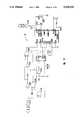
- FIG. 6is a schematic and block diagram illustrating one presently preferred embodiment of the base unit system diagram of FIG. 4, including the associated transmitter and receiver subsystems.
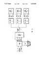
- FIG. 7(i.e. FIGS. 7A, 7B, 7C, 7D and 7E) is a schematic diagram of base unit subsystems described in FIG. 6.
- FIG. 8is a block diagram of an extension unit system controller and digital data multiplexer, including the associated transmitter and receiver subsystems.
- FIG. 9A and 9Bare a complete schematic diagram of the PN generator employed in FIGS. 6 through 8.
- the present inventionis adapted for use in a wide variety of specific communications applications, including telephone communications.
- the present inventionmay likewise be used with virtually any communications medium, such as, for example, RF signals or line carriers such as the power lines in a building. Nevertheless, in order to simplify the following discussion, the presently preferred embodiments of the present invention will be described below with specific reference to a telephone communications system which employs line carriers as the communications medium.
- MAmultiple access
- Time Division Multiple Access(TDMA), and two spread spectrum techniques, namely:
- CDMACode Division Multiple Access
- direct spreadwhich can include subcarrier CDMA
- FDMAFrequency Division Multiple Access
- TDMAtime division multiple access
- a single base unitinterfaces with the subscriber lines and transmission medium (AC power line) and controls the transmission of bidirection 1 voice data by breaking the transmissions into time frames and windows, in which each communications channel is assigned a specific transmit and receive time window.
- the system controllercan guarantee that only one transmission will occupy the medium at one time.
- the frequency with which each frame of windows is repeated (20-40 KHz)is high enough to transfer high speed voice data.
- CDMAcode division multiple access
- securityprivacy
- low interferencelow interference
- antijamming marginfrom interference and competing users.
- CDMAalso spreads the radiation spectrum of the transmission energy over a very wide bandwidth (2-10 MHz) so that the energy content of any licensed or unlicensed narrow band is too small to interfere with FCC licensed users.
- CDMAalso rejects many types of power line interference due to inherent "processing gain”; and the multiple access feature of using mutually orthogonal codes prevents jamming interference between users of similar telephone extension systems if their signals are below the "jamming margin". A discussion of these terms follows.
- Processing gainis acquired by using more bandwidth than the data requires. Processing gain is defined by the following equation: ##EQU1##
- Mjthe jamming margin
- a 10 dB Mjwould provide that ten jamming sources of equal strength or distance to the "friendly" signals could be rejected, or one "unfriendly" source of equal strength ten times closer, or one unfriendly source ten times greater in strength and equal in distance. For this reason, CDMA cannot be relied upon to carry the burden of jamming margin for near jamming sources.
- the CDMA jamming marginis also related to code length which is the number of code generator clock cycles ("chips") a code generator will cycle through before the code pattern repeats; but as long as the code length exceeds the processing gain, the main advantage gained by using long codes is privacy and security related.
- FDMAfrequency division multiple access
- FIG. 1illustrates one presently preferred embodiment of a line carrier telephone extension system in accordance with the present invention.
- the line carrier telephone extension system in FIG. 1services a plurality of subscriber lines 1-2 and corresponding extension phone sets 7, 10 and 13.
- Subscriber lines 1 and 2plug into base unit 3 which provides the interface circuitry and protocols for the subscriber line signals (including ring, off hook and duplex audio signals), and for multiple access power line carrier signals, which are carried through a building via AC power lines 4 to extension interface units 5, 8 and 11.
- the extension units 5 and 8are single line extensions and provide means to interface the multiple access line carrier signals to single line phone sets 7 and 10 via lines 6 and 9, respectively.
- Extension unit 11provides means to interface the multiple access line carrier signals to a multiline phone set 13 via lines 12.
- a line carrier system as illustrated in FIG. 1must operate in a manner which is transparent to the extension phone set user.
- base unit 3AC power lines 4 and extension unit 5
- an incoming ring signalis detected in the base unit, encoded into multiple access line carrier signals, transferred to the power lines 4, decoded in the extension unit 5 and converted to a ring signal for extension phone set 7.
- voice signalsare encoded into multiple access line carrier signals by converting the analog voice signals to digital representations using a analog-to-digital converters or CODECs
- an alternative embodiment of the inventioncould use a frequency-modulation encoding or modulation technique.
- Such encoding techniquesare well-known in the art.
- the preferred embodimentcan directly transmit digital data by eliminating the analog-to-digital converters and directly connecting a digital input in place of the output of the analog-to-digital converter.
- the preferred embodimentcan also directly produce digital output by eliminating the digital-to-analog converter in the receiving subsystem and using the digital signal previously connected to the digital-to-analog converter as the digital output.
- FIG. 2Another embodiment of a multiple access line carrier system in accordance with the present invention is illustrated in FIG. 2 and involves replacing conventional PAB extension lines 22 with multiple access line carrier systems, which can be easily installed and moved.
- subscriber lines 1-2connect to PABX unit 14 which provides a plurality of extension phone lines 22 and 15.
- Extension lines 15connect to multiple access base units 3 while some of the extension lines 22 connect in a conventional manner to other phone sets.
- Bas units 3interface the PABX signals to the AC power lines 4 of a building, as previously described.
- Multiple access extension units 5, 8 and 16interface the line carrier signals to phone sets 7, 10 and 18 via voice and data lines 6, 9, 17, and 19-21, said data lines 19-21 providing PABX control signals to phone sets 7, 10, and 18, or, alternatively, digital data for digital communications equipment, such as, for example, computers and fax machines.
- FIG. 3The relative advantages of using various multiple access techniques are depicted in FIG. 3.
- apartment #1 71has two phone lines 75 which are connected to a base unit 3 (FIG. 4) of the instant invention, not shown.
- Apartment #2 72adjoins apartment #1 71 and has one line 76 connected to a base unit 3.
- Apartment #3 73separates apartment #4 74 from apartment #2 72 and, while apartment #3 73 may have a phone line, it is not connected to a base unit.
- Apartment #4 74has a phone line 77 connected to a base unit.
- TDMAtime division multiple access
- the other two apartments 72 and 74have independent base units which use the same transmission medium as apartment 71, that is, the power lines of the same apartment building.
- FDMA techniquesare used to separate apartment #2 72 from the other two competitors (71 and 74), since the IF (intermediate frequency) filters of the units are sufficient to block strong local competitors of different frequencies, as will be described in further detail below. There is not sufficient bandwidth in the medium to provide more than a few alternate frequencies. Therefore, FDMA is used to avoid interference from competitors which are relatively "near" and, inevitably, relatively few.
- a multiple access base unit 3is functionally diagramed in FIG. 4 which illustrates subsystems selected from and providing a combination of two or more multiple access techniques: CDMA, FDMA and TDMA.
- the subscriber lines 1 and 2each connect to respective subscriber line interfaces 30 and 40, which each contain ring detect circuit 31, off hook circuit 32, and duplex audio circuit 33.
- the ring detect circuit 31converts an incoming subscriber line ring signal to a control signal for the system controller 42.
- Off hook circuit 32accepts an off hook command from system controller 42 and captures the subscriber line 1.
- Duplex audio circuit 33connects bidirectional audio signals between line 1 and digital signal processing (DSP) blocks 34 and 35 which interface with digital data MUX (multiplexer) 43 and system controller 42.
- the DSP blocksinclude analog-to-digital and digital-to-analog converters called codecs 34 and digital data compression/expansion circuits 35.
- the preferred embodimentcan directly transmit digital data by eliminating the analog-to-digital converters 34 and directly connecting a digital input in place of the output of the analog-to-digital converter 34.
- the preferred embodimentcan also directly produce digital output by eliminating the digital-to-analog converter 34 in the receiving subsystem and using the digital signal previously connected to the digital-to-analog converter 34 as the digital output. This could be used to provide a direct interface to an ISDN data or facsimile device.
- the TDMA (time division multiple access) subsystem 41between the system controller 42 and data MUX 43, multiplexes the transmit and receive functions performed in the CDMA/FDMA (code and frequency division multiple access) circuits with the incoming and outgoing voice data streams and control signals for ring and off hook/busy.
- the system controller 42divides the total system time into blocks of 10 microsecond duration. During the first half of the block the base unit 3 transmitter is enabled, and transmits data from subscriber lines 1 and 2 in two 2.5 microsecond windows to the extension units 5, 8 and 11 (see FIG. 1).
- the base unit 3 receiveris enabled and data is received from two extension units in two 2.5 microsecond windows and transferred t subscriber lines 1 and 2 via subscriber line interfaces 30 and 40. Short time spaces between transmit and receive windows and modes allows for signal propagation delays between the base and extension units.
- FIG. 4illustrates the use of CDMA and FDMA in the line carrier transceiver section.
- a pseudonoise (PN) code generator 44 and carrier frequency oscillator 56by means of a modulator 48, produces a spread spectrum line carrier.
- the oscillator 56runs at 10 MHz and the PN code rate is 5 MHz, producing a spread spectrum main lobe bandwidth from 5 to 15 MHz.
- Use of 4095+ bit (chip) code lengthensures reasonable privacy and security and minimizes interference with other types of equipment.
- An FSK (frequency shift key) modulator 49modulates the carrier with the data to be transmitted.
- Some other forms of data modulationcan also work with spread spectrum modulation, such as BPSK (biphase shift key), QPSK (quadriphase shift key), MSK (minimum shift key) and FM (frequency modulation).
- Code selection switches and oscillator/carrier frequency switchescan provide user changeability of CDMA and FDMA parameters to minimize collision potentials between physically proximate systems.
- the base receivercomprises a plurality of PN (pseudonoise) generators 45 an 46 which are delayed in time from the transmitter PN generator 44 as selected by the system controller via PN MUX (multiplexer) 47 to provide the correct PN phase to the CDMA correlator 52 permitting correlation of extension CDMA signals coming from the AC lines 4 through coupler 55 and filter 51 to said correlator/demodulator 52.
- the correlated receiver signalsare amplified and filtered by IF 53 prior to demodulation by data demodulator 54.
- the digital data MUX 43insures that the right data is transferred to the right subscriber line interface during its assigned TDMA window.
- TDMAtime division multiple access for transmit and receive modes as well as for the duplex data for each subscriber line allows the transmitters and receivers of both the base 3 and extension units 5, 8, and 11 (see FIG. 1) to operate at the same carrier and IF frequencies. Frequency division multiple access is not required if no near neighbors are using the transmission medium.
- Another embodiment of the present inventiondoes not require the use of TDMA (time division multiple access) if FDMA (frequency division multiple access) is employed for each data channel.
- the transmitters in the base 3 and extension units 5, 8, and 11send data on two or more carrier frequencies simultaneously, and the receivers have corresponding correlators 52 for each transmitted data channel.
- Carrier frequencies and corresponding heterodyne correlator frequenciescan be synthesized so that single or multiple IF's (intermediate frequencies) can be employed to reduce mutual interference between subsystems in a unit.
- Differing CDMA codescan also be used in each data channel to reduce mutual interference with other data channels. Care must also be taken to avoid collisions between carrier and code rate harmonics.
- FIG. 5illustrates one presently preferred embodiment of a multiple access extension unit in accordance with the present invention.
- the extension unit diagramed in FIG. 5contains most of the same subsystems as the base unit of FIG. 4, and the same reference numerals are accordingly employed. There is, however, one notable exception: the additional PN (pseudonoise) generators 45 and 46 of the base unit are omitted in the extension unit.
- the same type of PN code generator 44which is used to correlate the received spread spectrum carrier signal in the base unit is used in the extension unit to CDMA modulate the transmitter data returning to the base unit.
- multiple access carrier signals from the base unit 3are carried by power lines 4 to extension units 5, 8 and 11 and coupled via AC line coupler 55 and filter 51 into the CDMA correlator 52.
- the recovered data modulated carrieris amplified and filtered by IF (intermediate frequency) amplifier 53 and sent to data demodulator 54 where the data is recovered and multiplexed 43 to the extension phone interface 60 where digital decompression (expansion) 65 and digital to analog converter 64 provide duplex audio to the extension phone line 6 and set 7.
- IFintermediate frequency
- audio returning from the extension line 7 to the subscriber line 1passes through duplex conversion 63, A/D conversion 64 and DSP compression 65 to TDMA controller 57 where data MUX 43 sends the signal in its appropriate time window to data modulator 49, CDMA modulator 48, power amp 50 and AC line coupler 55 into power lines 4 and on its way to the base unit 3.
- the system controller 58 of the extension unit of FIG. 5can differ from the system controller 42 of the base unit 3 in that the former contains multiple extension arbitration logic. For example, in one embodiment, only one extension phone set is permitted to use one subscriber line at a time. If several extension sets are assigned to one subscriber line and a first extension is using that line, then when a second extension set is taken off hook, the second extension unit will check the base unit transmissions to determine that the assigned subscriber channel is already in use by an other extension unit and will emit a busy tone to the second extension phone set. Desired protocols may be installed in the system control logic to handle various requirements. A programable logic device can be used to implement this function and provides for reprogramming the desired protocols.
- FIG. 6 and 7illustrate in more detail a block diagram and schematic diagram of one preferred embodiment derived from the functional block diagram of FIG. 4.
- FIG. 6 and 7illustrate in more detail a block diagram and schematic diagram of one preferred embodiment derived from the functional block diagram of FIG. 4.
- FIGS. 6 and 7illustrate a specific embodiment of the system controller 41 for a base unit 3 in which three multiple access techniques are employed to provide a two line extension system, which requires four data channels, two for each line.
- FDMAfrequency division multiple access
- FIGS. 6 and 7illustrate a specific embodiment of the system controller 41 for a base unit 3 in which three multiple access techniques are employed to provide a two line extension system, which requires four data channels, two for each line.
- FDMAfrequency division multiple access
- CDMAcode division multiple access
- PNpseudodonoise code generators 44-3, 45-4 and 46-4 to reduce mutual interference between the stronger local transmitter signals and the weaker extension unit signals.
- thisis accomplished by offsetting the phase relationships of the similar code sequences of the three PN generators relative to one another. This code phase offset is partly accomplished as a natural consequence of the differing distances of the extension units 5, 8 and 11 from the base unit 3 (see FIG. 1).
- TDMAtime division multiple access
- the divide by 64 line select counter 42-1is reset, and the 4.28 MHz chip clock from 44-2 clocks both the PN generator 44-3 and the TDMA line selector 42-1, which alternately selects data at the rate of 67 KHz, providing a bit rate for each channel of 33.5 KHz or 67 KBs.
- Power line interface or AC line coupler 55connects bidirectional carrier signals from AC power lines 4 to the transmitter 50 and receiver 51.
- the output of transmitter oscillator 56is doubled by a conventional pulse edge detector frequency doubler 44-1 and subsequently divided by five with counter 44-2, producing a 4.28 MHz chip clock for clocking PN generator 44-3, said PN generator having 13 stages and producing an 8191 chip long code sequence and a sync out pulse at the start of each new sequence for resetting line select counter 42-1.
- the 4.28 MHz chip clockalso clocks the line select counter 42-1, which clocks line 1 and line 2 data multiplexers 43-1,2,3,4 as well as seek multiplexer 43-1 and PN multiplexer 47.
- line 1 and line 2transmit data from the subscriber line interfaces enter transmit data MUX 43-1, where the data modulates the 10.7 MHz carrier at 49 and which is further code division multiple access modulated at 48 and via transmitter output 50 sent to the power line coupler 55.
- the receiver data for sending back to the subscriber line interfaceis received from the power line 4 via interface 55 and filter 51 and presented to CDMA correlator 52 which recovers the data modulated 6 MHz carrier 53.
- Separate PN generators 45 and 46are provided because the distance from the base unit and resulting propagation delay for each extension unit may differ, which causes the PN phase relationships between the transmitter PN[0] generator 44-3 and the receivers' PN[1] 45-4 and PN[2] 46-4 to be delayed in time.
- each receiver PN generatorsynchronizes with that of the extension unit transmitter. This is achieved by providing a PN code seek and lock circuit consisting of 90 degree lag circuit 43-6 in combination with phase multiplexers 45-1 and 46-1, seek multiplexer 43-5 and the correlation output of data demodulator 54.
- the seek functionis provided at all times when correlation is not detected, and is effected by individually retarding the phase of the clock signal (10.7 MHz) input to each uncorrelated receiver PN generator (PN[1] 45-2,3,4 and PN[2] 46-2,3,4) at the line select rate by means of 90 degree lag circuit 43-6 and phase multiplexers 1 and 2 45-1 and 46-1.
- the 90 degree lag circuit 43-6supplies all four phases of the clock to the phase multiplexers, which select in a retarding order one of the phases by means of a two bit binary counter which is clocked by each line select pulse.
- the seek mode of operationcontinuously and progressively retards each receiver PN code phase by 90 degrees every 64 chips until the data demodulator detects correlation of an incoming signal from one of the extension units assigned to a specific line, whereupon the seek mode for that line is converted to the operating mode for said line and the phase multiplexer and PN generator hold the correlating phase relationship and the transmit and receive data channels for said line are activated.
- the seek multiplexer 43-5insures that the uncorrelated channel for the unused line continues in the seek mode until correlation for said unused line is detected.
- ring detect 31, off hook circuit 32 and duplex audio circuit 33are elements of a subscriber loop interface circuit ("SLCI").
- the codec 34 and compression function 35can be constructed with industry standard 2913-2917 devices.
- the codeccan also be a newer oversampled sigma-delta coder with DSP decimation and companding, as described in several articles such as that by Freedman et al., "IEEE Journal of Solid-State Circuits", Vol. 24, No. 2 (U.S.A., April 1989), pp. 274-280, and manufactured by AT&T as a T7510.
- the PN (pseudo noise) code generatorcan be a 13 stage modular shift register generator (MSRG) or a Gold code sequence generator as described by Dixon at pp. 65-81 and implemented with MC8504's (or equivalent shift register chips) and exclusive-or gates.
- the CDMA modulator 48can be as simple as an exclusive-or gate with the carrier frequency and the PN code as its inputs or a balanced modulator such as a Signetics NE602 or older circuits described by Dixon at pp. 109-113.
- the CDMA correlator/demodulator 52can be an NE602.
- the IF (intermediate frequency) amplifier and filter 53 and demodulator 54can consist of an NE604 or a CA3089.
- the digital data MUX 43consists of digital gates or bilateral switches (CD4066).
- the TDMA (time division multiple access) system controller 42is a unique sequential and state logic machine, an embodiment of which is described in detail above in connection with FIG. 6.
- cost and size limitationsapply to discrete implementation of complex circuit embodiments, which motivates the integration of most functions of the present invention into a single low-cost application specific integrated circuit (ASIC).
- ASICapplication specific integrated circuit
- Power line interface 55connects the power line 4 with the transmitter 50 and receiver 51.
- the transmitteroperates at a carrier frequency of 6 MHz which is substantially different from that of the receiver's 10.7 MHz 56-1.
- a sufficient difference in carrier frequencyallows for simultaneous operation of both the receiver 51 and transmitter 50 with support from other subsystems including filters and hybrid circuitry in power line interface 55 and a phase offset in receive and transmit pseudonoise (PN) codes at PN code generator 44-3, said code offset providing a spreading instead of a correlation of the transmitter signal 50 which may bleed over into the receiver 51.
- PNpseudonoise
- the base carrier signalenters the filter 51 and is correlated and mixed with the PN code at correlator 52 recovering the data modulated intermediate frequency signal at 53, which signal is demodulated at 54 and the data sent to data demultiplexer 43-3 and 43-4, which demultiplexer sends the correct data to line 1 and line 2 extension phone interfaces.
- Multiple extension arbitration logic 58-1continuously monitors the data and operating state of each line to provide a busy tone indicator to a user of one extension unit attempting to use a line which is being used by another extension unit. This is possible because all extension units 5 receive data from the base unit 3 but do not transmit data back to said base unit unless a user takes the particular extension unit off hook and the line is not already in use by another extension unit.
- the arbitration logic controlleris composed of several gates and flip-flops.
- PN code correlationis provided by a seek circuit composed of 10.7 MHz oscillator 56-1, 90 degree lag 56-2 and phase multiplexer 43-6, which multiplexer clocks the PN generator 44-1,2,3 and periodically selects the next 90 degree retarded phase of the oscillator during correlation seeking state of the receiver, until the data demodulator detects a strong and correlated intermediate frequency signal at receiver IF 53, whereupon seeking is terminated and the base and extension PN codes are synchronized.
- the sync output of the PN generator 44-3resets the time division multiple access line select counter 42-1, which divides the chip (PN clock) rate by 64 or another suitable number depending on clock rates and data rates.
- the line select output of counter 42-1drives the received data demultiplexer 43-3 as well as the transmit data multiplexer 43-1, which selects which data modulates the 6 MHz carrier oscillator 54-1 at transmitter 49 and is mixed with PN code at mixer 48 for transmission back to the base unit by output 50.
- FIG. 3applies to a cordless telephone system as well as to a line carrier system.
- the present inventionprovides an effective method of multiple access communication which provides for multiple access of a plurality of signals on a single communications medium.
- the system and method of the present inventionalso utilizes both TDMA (time division multiple access) and CDMA (code division multiple access) to permit high data rates and multiple access by two or more telephone lines.
- CDMAcode division multiple access
- CDMAis also utilized to provide a high degree of security for preventing unauthorized access to the subscriber's line, and which provides privacy with respect to the conversation from third parties.
- the present inventionprovides a method and system of code synchronization to provide multiple extensions for the same subscriber line which do not interfere with each other.
- the system and method of the present inventionutilizes FDMA (frequency division multiple access) in combination with CDMA (code division multiple access) to prevent interference between relatively close neighboring transmission systems or partner transmissions in the same system and to provide for multiple access (simultaneous transmission) of duplex signals for at least one telephone line.
- FDMAfrequency division multiple access
- CDMAcode division multiple access
- the present inventionprovides a method and system of multiple access telephone extension communications which applies equally well to both cordless and line carrier telephone extension systems and methods.
Landscapes
- Engineering & Computer Science (AREA)
- Signal Processing (AREA)
- Computer Networks & Wireless Communication (AREA)
- Power Engineering (AREA)
- Mobile Radio Communication Systems (AREA)
Abstract
Description
TABLE I ______________________________________ Specific Electrical Components Comprising the Embodiment of FIGS. 4-6 Reference No. Part No. Manufacturer ______________________________________ 31MC33120 Motorola 32MC33120 Motorola 33MC33120 Motorola 34 2913 {Texas Instruments 35 2917 {Intel Lattice 42 42-1 74393 National,Motorola,Etc. 43 43-1 74157 43-2 7404 43-3 7474 43-4 7474 43-5 75157 43-6 7474 44 44-1 7408,-14,-32 44-2 7490 44-3 74194, 7474, 7486 45 45-1 74157 45-2 7414, 7408 45-3 7490 45-4 74194, 7474, 7486 46 46-1 74157 46-2 7414, 7408 46-3 7490 46-4 74194, 7474, 7486 47 74157 48 NE602, 7486Signetics 49 7486 50 7404 51 RC, LCLow Pass Filter 52 NE602Signetics 53NE604 Signetics 54 NE604 Signetics 54-1 55 56 57 58 61 62 63 64 65 ______________________________________
Claims (19)
Priority Applications (8)
| Application Number | Priority Date | Filing Date | Title |
|---|---|---|---|
| US07/773,009US5319634A (en) | 1991-10-07 | 1991-10-07 | Multiple access telephone extension systems and methods |
| BR9206605ABR9206605A (en) | 1991-10-07 | 1992-10-06 | Telephone extension multiple access methods and systems |
| JP5507147AJP2572940B2 (en) | 1991-10-07 | 1992-10-06 | Multiple access extension telephone system and method |
| DE69233034TDE69233034D1 (en) | 1991-10-07 | 1992-10-06 | METHOD AND SYSTEM FOR TELEPHONE EXTENSIONS WITH MULTIPLE ACCESS |
| CA002119378ACA2119378C (en) | 1991-10-07 | 1992-10-06 | Multiple access telephone extension systems and methods |
| AU28613/92AAU2861392A (en) | 1991-10-07 | 1992-10-06 | Multiple access telephone extension systems and methods |
| EP92921830AEP0607304B1 (en) | 1991-10-07 | 1992-10-06 | Multiple access telephone extension systems and methods |
| PCT/US1992/008510WO1993007693A1 (en) | 1991-10-07 | 1992-10-06 | Multiple access telephone extension systems and methods |
Applications Claiming Priority (1)
| Application Number | Priority Date | Filing Date | Title |
|---|---|---|---|
| US07/773,009US5319634A (en) | 1991-10-07 | 1991-10-07 | Multiple access telephone extension systems and methods |
Publications (1)
| Publication Number | Publication Date |
|---|---|
| US5319634Atrue US5319634A (en) | 1994-06-07 |
Family
ID=25096902
Family Applications (1)
| Application Number | Title | Priority Date | Filing Date |
|---|---|---|---|
| US07/773,009Expired - LifetimeUS5319634A (en) | 1991-10-07 | 1991-10-07 | Multiple access telephone extension systems and methods |
Country Status (8)
| Country | Link |
|---|---|
| US (1) | US5319634A (en) |
| EP (1) | EP0607304B1 (en) |
| JP (1) | JP2572940B2 (en) |
| AU (1) | AU2861392A (en) |
| BR (1) | BR9206605A (en) |
| CA (1) | CA2119378C (en) |
| DE (1) | DE69233034D1 (en) |
| WO (1) | WO1993007693A1 (en) |
Cited By (148)
| Publication number | Priority date | Publication date | Assignee | Title |
|---|---|---|---|---|
| US5434905A (en)* | 1993-11-30 | 1995-07-18 | Uniden Corporation | Digital cordless telephone set operated under burst synchronization |
| US5465256A (en)* | 1993-12-23 | 1995-11-07 | Krone Ag | Telephone cross connect status signal pre-processor |
| US5481533A (en)* | 1994-05-12 | 1996-01-02 | Bell Communications Research, Inc. | Hybrid intra-cell TDMA/inter-cell CDMA for wireless networks |
| US5517552A (en)* | 1995-04-05 | 1996-05-14 | Matsushita Electric Industrial Co., Ltd. | Facsimile apparatus with cordless phone, a ring signal detection, an interface portion, a facsimile communication start signal detection and a first and second modes of operation |
| WO1996017431A1 (en)* | 1994-11-30 | 1996-06-06 | Pacific Communication Sciences, Inc. | Universal radio architecture for low-tier personal communication system |
| US5530697A (en)* | 1994-02-07 | 1996-06-25 | Fujitsu Limited | Code-division multiplex communication apparatus |
| US5579321A (en)* | 1993-03-15 | 1996-11-26 | U.S. Philips Corporation | Telecommunication system and a main station and a substation for use in such a system |
| FR2734680A1 (en)* | 1995-05-22 | 1996-11-29 | Nec Corp | TDMA communication system for images and speech |
| US5640674A (en) | 1991-04-08 | 1997-06-17 | Omnipoint Corporation | Three-cell wireless communication system |
| US5640413A (en)* | 1993-01-21 | 1997-06-17 | Nec Corporation | Digital mobile radio communication system |
| US5648955A (en) | 1993-11-01 | 1997-07-15 | Omnipoint Corporation | Method for power control in a TDMA spread spectrum communication system |
| US5648982A (en) | 1994-09-09 | 1997-07-15 | Omnipoint Corporation | Spread spectrum transmitter |
| US5680414A (en) | 1994-09-09 | 1997-10-21 | Omnipoint Corporation | Synchronization apparatus and method for spread spectrum receiver |
| WO1997043836A1 (en)* | 1996-05-16 | 1997-11-20 | Northern Telecom Limited | Power line communication employing cordless telephone standard |
| US5694414A (en) | 1991-05-13 | 1997-12-02 | Omnipoint Corporation | Multi-band, multi-mode spread-spectrum communication system |
| US5724610A (en)* | 1994-06-30 | 1998-03-03 | Hyundai Electronics Industries Co., Ltd. | Selector bank subsystem of CDMA system using a pair of first processors for selecting channels between CDMA interconnect subsystem and mobile service switch center |
| US5742638A (en) | 1991-12-16 | 1998-04-21 | Omnipoint Corporation | Spread-spectrum data publishing system |
| US5745837A (en)* | 1995-08-25 | 1998-04-28 | Terayon Corporation | Apparatus and method for digital data transmission over a CATV system using an ATM transport protocol and SCDMA |
| US5754585A (en) | 1994-09-09 | 1998-05-19 | Omnipoint Corporation | Method and apparatus for serial noncoherent correlation of a spread spectrum signal |
| US5754584A (en) | 1994-09-09 | 1998-05-19 | Omnipoint Corporation | Non-coherent spread-spectrum continuous-phase modulation communication system |
| US5757847A (en) | 1994-09-09 | 1998-05-26 | Omnipoint Corporation | Method and apparatus for decoding a phase encoded signal |
| US5764685A (en)* | 1994-04-26 | 1998-06-09 | Uniden Corporation | Method of setting spread code series and communication apparatus using spread spectrum communication method |
| US5768269A (en)* | 1995-08-25 | 1998-06-16 | Terayon Corporation | Apparatus and method for establishing frame synchronization in distributed digital data communication systems |
| US5787076A (en) | 1993-11-01 | 1998-07-28 | Omnipoint Corporation | Multi-mode TDMA spread spectrum communication system |
| US5790527A (en)* | 1994-12-20 | 1998-08-04 | Research Triangle Park | Trunked radio frequency communication system for accommodating both frequency and time division based RF communications |
| US5790587A (en) | 1991-05-13 | 1998-08-04 | Omnipoint Corporation | Multi-band, multi-mode spread-spectrum communication system |
| US5793759A (en)* | 1995-08-25 | 1998-08-11 | Terayon Corporation | Apparatus and method for digital data transmission over video cable using orthogonal cyclic codes |
| US5796772A (en) | 1991-05-13 | 1998-08-18 | Omnipoint Corporation | Multi-band, multi-mode spread-spectrum communication system |
| US5805583A (en)* | 1995-08-25 | 1998-09-08 | Terayon Communication Systems | Process for communicating multiple channels of digital data in distributed systems using synchronous code division multiple access |
| US5805581A (en)* | 1994-09-09 | 1998-09-08 | Mitsubishi Denki Kabushiki Kaisha | Mobile communication system using various multiple access methods |
| US5815525A (en) | 1991-05-13 | 1998-09-29 | Omnipoint Corporation | Multi-band, multi-mode spread-spectrum communication system |
| US5818821A (en) | 1994-12-30 | 1998-10-06 | Intelogis, Inc. | Universal lan power line carrier repeater system and method |
| US5832364A (en)* | 1995-10-06 | 1998-11-03 | Airnet Communications Corp. | Distributing wireless system carrier signals within a building using existing power line wiring |
| US5852785A (en) | 1993-03-22 | 1998-12-22 | Bartholomew; David B. | Secure access telephone extension system and method in a cordless telephone system |
| US5881100A (en) | 1994-09-09 | 1999-03-09 | Omnipoint Corporation | Method and apparatus for coherent correlation of a spread spectrum signal |
| US5884148A (en)* | 1996-07-08 | 1999-03-16 | Omnipoint Corporation | Wireless local loop system and method |
| US5887020A (en) | 1991-05-13 | 1999-03-23 | Omnipoint Corporation | Multi-band, multi-mode spread-spectrum communication system |
| WO1999000906A3 (en)* | 1997-06-27 | 1999-04-15 | Adc Telecommunications Inc | System and method for distributing rf signals |
| US5911119A (en)* | 1993-03-22 | 1999-06-08 | Phonex Corporation | Secure cordless telephone extension system and method |
| US5915217A (en)* | 1991-10-10 | 1999-06-22 | Space Systems/Loral, Inc. | Worldwide telecommunications system using satellites |
| US5926755A (en)* | 1996-08-07 | 1999-07-20 | Telefonaktiebolaget Lm Ericsson | Method and an arrangement for conducting multiple calls simultaneously |
| US5929750A (en)* | 1992-10-22 | 1999-07-27 | Norweb Plc | Transmission network and filter therefor |
| US5949327A (en)* | 1994-08-26 | 1999-09-07 | Norweb Plc | Coupling of telecommunications signals to a balanced power distribution network |
| US5953370A (en) | 1994-09-09 | 1999-09-14 | Omnipoint Corporation | Apparatus for receiving and correlating a spread spectrum signal |
| US5963586A (en) | 1994-09-09 | 1999-10-05 | Omnipoint Corporation | Method and apparatus for parallel noncoherent correlation of a spread spectrum signal |
| WO1999052220A1 (en)* | 1998-04-08 | 1999-10-14 | Phonex Corporation | Distribution system for external communication signals and data |
| US5970127A (en) | 1997-10-16 | 1999-10-19 | Phonex Corporation | Caller identification system for wireless phone jacks and wireless modem jacks |
| US5991308A (en)* | 1995-08-25 | 1999-11-23 | Terayon Communication Systems, Inc. | Lower overhead method for data transmission using ATM and SCDMA over hybrid fiber coax cable plant |
| US5991625A (en) | 1991-06-03 | 1999-11-23 | Omnipoint Corporation | Spread spectrum wireless telephone system |
| US6021137A (en)* | 1996-08-27 | 2000-02-01 | Uniden Corporation | Data collection system |
| WO2000010264A1 (en)* | 1998-08-14 | 2000-02-24 | Phonex Corporation | Conversion and distribution of incoming wireless telephone signals using the power line |
| US6038223A (en)* | 1997-10-22 | 2000-03-14 | Telefonaktiebolaget Lm Ericsson (Publ) | Access scheme for packet data in a digital cellular communication system |
| US6055435A (en) | 1997-10-16 | 2000-04-25 | Phonex Corporation | Wireless telephone connection surge suppressor |
| WO2000038346A1 (en)* | 1998-12-22 | 2000-06-29 | Siemens Aktiengesellschaft | Method for transmitting communications information and corresponding communications unit and communications system |
| US6097817A (en)* | 1997-12-10 | 2000-08-01 | Omnipoint Corporation | Encryption and decryption in communication system with wireless trunk |
| US6107912A (en) | 1997-12-08 | 2000-08-22 | Phonex Corporation | Wireless modem jack |
| WO2000049796A1 (en)* | 1999-02-22 | 2000-08-24 | Phonex Corporation | Digital telephony carrier current system |
| US6144292A (en)* | 1992-10-22 | 2000-11-07 | Norweb Plc | Powerline communications network employing TDMA, FDMA and/or CDMA |
| EP0714193A3 (en)* | 1994-11-24 | 2000-11-22 | Marconi Communications Limited | Improved telecommunication system through mains electricity conductors |
| US6167278A (en)* | 1986-10-22 | 2000-12-26 | Nilssen; Ole K. | Combination cordless-cellular telephone system |
| WO2000079697A1 (en)* | 1999-06-18 | 2000-12-28 | Dynamic Telecommunications, Inc. | Wireless local distribution system using standard power lines |
| US6208627B1 (en) | 1997-12-10 | 2001-03-27 | Xircom, Inc. | Signaling and protocol for communication system with wireless trunk |
| US6212204B1 (en)* | 1995-11-22 | 2001-04-03 | Clayton S. Depue | Subscriber line multiplexer |
| US6243571B1 (en) | 1998-09-21 | 2001-06-05 | Phonex Corporation | Method and system for distribution of wireless signals for increased wireless coverage using power lines |
| EP0839428A4 (en)* | 1995-07-18 | 2001-07-18 | Adaptive Networks Inc | Reconfigurable on-demand telephone and data line system |
| US6272395B1 (en)* | 1997-11-03 | 2001-08-07 | Ident, Inc. | System and method for reporting vending status |
| US6282228B1 (en) | 1997-03-20 | 2001-08-28 | Xircom, Inc. | Spread spectrum codes for use in communication |
| US6282405B1 (en) | 1992-10-22 | 2001-08-28 | Norweb Plc | Hybrid electricity and telecommunications distribution network |
| EP0822721A3 (en)* | 1996-08-02 | 2001-09-12 | Siemens Aktiengesellschaft | Subscriber terminal connecting system for interactive telecommunication services |
| US6307868B1 (en) | 1995-08-25 | 2001-10-23 | Terayon Communication Systems, Inc. | Apparatus and method for SCDMA digital data transmission using orthogonal codes and a head end modem with no tracking loops |
| US6320867B1 (en)* | 1998-05-27 | 2001-11-20 | 3Com Corporation | Method and apparatus for hierarchical management of subscriber link traffic on digital networks |
| US20020002040A1 (en)* | 2000-04-19 | 2002-01-03 | Kline Paul A. | Method and apparatus for interfacing RF signals to medium voltage power lines |
| WO2001050625A3 (en)* | 1999-12-30 | 2002-01-24 | Siemens Ag | Conversion of a two-directional so data stream for transmission via a low voltage power network |
| US6356555B1 (en) | 1995-08-25 | 2002-03-12 | Terayon Communications Systems, Inc. | Apparatus and method for digital data transmission using orthogonal codes |
| US6359923B1 (en) | 1997-12-18 | 2002-03-19 | At&T Wireless Services, Inc. | Highly bandwidth efficient communications |
| WO2001047294A3 (en)* | 1999-12-20 | 2002-03-21 | Tantivy Comm Inc | Method and apparatus for a spectrally compliant cellular communication system |
| US20020034217A1 (en)* | 1997-02-24 | 2002-03-21 | At&T Wireless Services, Inc. | Adaptive weight update method and system for a discrete multitone spread spectrum communications system |
| US20020118101A1 (en)* | 2001-02-14 | 2002-08-29 | Kline Paul A. | Data communication over a power line |
| WO2002069533A3 (en)* | 2000-10-27 | 2002-10-31 | L 3 Comm Corp | Two-dimensional channel bonding in a hybrid cdma/fdma fixed wireless access system to provide finely variable rate channels |
| US20020167928A1 (en)* | 2001-05-14 | 2002-11-14 | Interdigital Technology Corporation | Physical channel configuration signaling procedures |
| WO2002093878A1 (en)* | 2001-05-17 | 2002-11-21 | Gemini Industries, Inc. | Telephone line extension |
| US20020176581A1 (en)* | 1997-12-10 | 2002-11-28 | Bilgic Izzet M. | Authentication and security in wireless communication system |
| US6496104B2 (en) | 2000-03-15 | 2002-12-17 | Current Technologies, L.L.C. | System and method for communication via power lines using ultra-short pulses |
| US20020191579A1 (en)* | 2001-05-14 | 2002-12-19 | Interdigital Technology Corporation | Physical channel configuration signaling procedures |
| US6526026B1 (en) | 1997-12-10 | 2003-02-25 | Intel Corporation | Digit transmission over wireless communication link |
| US6535499B1 (en)* | 1998-02-27 | 2003-03-18 | Fujitsu Limited | Multi-mode communication device |
| US6546245B1 (en)* | 1999-10-05 | 2003-04-08 | Agere Systems Inc. | Inverted code sequence cordless signaling |
| US6556167B1 (en)* | 1999-05-28 | 2003-04-29 | Rockwell Collins, Inc. | Direct acquisition of very large PN sequences in GPS systems |
| US6560209B1 (en) | 1997-02-06 | 2003-05-06 | At&T Wireless Services, Inc. | Method for frequency division duplex communications |
| US6567474B1 (en) | 1999-03-02 | 2003-05-20 | Phonex Corporation | Digital wireless phone/modem jack capable of communications over the power lines using differential binary phase shift keying (DBPSK) |
| US20030100288A1 (en)* | 2001-11-29 | 2003-05-29 | General Electric Company One Research Circle | Universal PLC radio frequency enhanced bridge |
| EP1043866A3 (en)* | 1999-04-08 | 2003-07-23 | Siemens Aktiengesellschaft | Arrangement for home area data transmission |
| US6665308B1 (en) | 1995-08-25 | 2003-12-16 | Terayon Communication Systems, Inc. | Apparatus and method for equalization in distributed digital data transmission systems |
| US6697618B1 (en)* | 2000-04-19 | 2004-02-24 | Phonex Broadband Corporation | System and method for detecting failures in a wireless phone/modem jack to prevent telephone line seizures |
| US20040043751A1 (en)* | 1999-12-20 | 2004-03-04 | Tantivy Communications, Inc. | Method and apparatus for a spectrally compliant cellular communication system |
| US20040067745A1 (en)* | 2002-10-02 | 2004-04-08 | Amperion, Inc. | Method and system for signal repeating in powerline communications |
| US20040135676A1 (en)* | 2002-12-10 | 2004-07-15 | Berkman William H. | Power line communication system and method of operating the same |
| US6775297B1 (en) | 1992-12-31 | 2004-08-10 | James C. Shelby | Computer-based conversion of digital signals |
| US6778817B1 (en) | 1998-12-01 | 2004-08-17 | Phonex Corporation | Method and system for combining wireless phone jack and RF wireless communications |
| US6782039B2 (en) | 1997-02-24 | 2004-08-24 | At&T Wireless Services, Inc. | Vertical adaptive antenna array for a discrete multitone spread spectrum communications system |
| US6785300B2 (en) | 1997-02-06 | 2004-08-31 | At&T Wireless Services, Inc. | Delay compensation |
| WO2004091113A1 (en)* | 2003-04-08 | 2004-10-21 | Acn Advanced Communications Networks Sa | System and method for data communication over power lines |
| US20040218576A1 (en)* | 2001-07-27 | 2004-11-04 | Yasumi Imagawa | Receiver and communication terminal |
| US20050007241A1 (en)* | 2000-01-20 | 2005-01-13 | Kline Paul A. | Method of isolating data in a power line communications network |
| US20050129069A1 (en)* | 2003-03-13 | 2005-06-16 | Yehuda Binder | Private telephone network connected to more than one public network |
| US6947469B2 (en) | 1999-05-07 | 2005-09-20 | Intel Corporation | Method and Apparatus for wireless spread spectrum communication with preamble processing period |
| US6950567B2 (en) | 2001-02-14 | 2005-09-27 | Current Technologies, Llc | Method and apparatus for providing inductive coupling and decoupling of high-frequency, high-bandwidth data signals directly on and off of a high voltage power line |
| US6965302B2 (en) | 2000-04-14 | 2005-11-15 | Current Technologies, Llc | Power line communication system and method of using the same |
| US6965303B2 (en) | 2002-12-10 | 2005-11-15 | Current Technologies, Llc | Power line communication system and method |
| US6977578B2 (en) | 2000-01-20 | 2005-12-20 | Current Technologies, Llc | Method of isolating data in a power line communications network |
| US6980091B2 (en) | 2002-12-10 | 2005-12-27 | Current Technologies, Llc | Power line communication system and method of operating the same |
| US6980089B1 (en) | 2000-08-09 | 2005-12-27 | Current Technologies, Llc | Non-intrusive coupling to shielded power cable |
| US6980090B2 (en) | 2002-12-10 | 2005-12-27 | Current Technologies, Llc | Device and method for coupling with electrical distribution network infrastructure to provide communications |
| US6982611B2 (en) | 2002-06-24 | 2006-01-03 | Current Technologies, Llc | Power line coupling device and method of using the same |
| US6998962B2 (en) | 2000-04-14 | 2006-02-14 | Current Technologies, Llc | Power line communication apparatus and method of using the same |
| US7009958B1 (en)* | 2000-05-19 | 2006-03-07 | At&T Corp. | Unified encoding process for generalized multiple access |
| US7046124B2 (en) | 2003-01-21 | 2006-05-16 | Current Technologies, Llc | Power line coupling device and method of using the same |
| US7053756B2 (en) | 2001-12-21 | 2006-05-30 | Current Technologies, Llc | Facilitating communication of data signals on electric power systems |
| US7075414B2 (en) | 2003-05-13 | 2006-07-11 | Current Technologies, Llc | Device and method for communicating data signals through multiple power line conductors |
| US7076378B1 (en) | 2002-11-13 | 2006-07-11 | Current Technologies, Llc | Device and method for providing power line characteristics and diagnostics |
| US7102478B2 (en) | 2002-06-21 | 2006-09-05 | Current Technologies, Llc | Power line coupling device and method of using the same |
| US20060197428A1 (en)* | 2005-02-21 | 2006-09-07 | Takeshi Tonegawa | Electron devices with non-evaporation-type getters and method for manufacturing the same |
| US7113134B1 (en) | 2004-03-12 | 2006-09-26 | Current Technologies, Llc | Transformer antenna device and method of using the same |
| US20060221995A1 (en)* | 2005-04-04 | 2006-10-05 | Berkman William H | Multi-function modem device |
| US7132819B1 (en) | 2002-11-12 | 2006-11-07 | Current Technologies, Llc | Floating power supply and method of using the same |
| US20070053352A1 (en)* | 2005-09-06 | 2007-03-08 | Corcoran Kevin F | Power line communications system with differentiated data services |
| US7190683B2 (en) | 2000-10-27 | 2007-03-13 | L-3 Communications Corporation | Two-dimensional channel bonding in a hybrid CDMA/FDMA fixed wireless access system to provide finely variable rate channels |
| US7199699B1 (en) | 2002-02-19 | 2007-04-03 | Current Technologies, Llc | Facilitating communication with power line communication devices |
| US20070091800A1 (en)* | 2005-10-21 | 2007-04-26 | Corcoran Kevin F | Power line communication voice over IP system and method |
| US20070189182A1 (en)* | 2006-02-14 | 2007-08-16 | Berkman William H | Method for establishing power line communication link |
| US7274688B2 (en) | 2000-04-18 | 2007-09-25 | Serconet Ltd. | Telephone communication system over a single telephone line |
| US7292626B1 (en)* | 2001-06-04 | 2007-11-06 | National Semiconductor Corporation | Method and system for efficient quantization in DAC and ADC for discrete multitone systems |
| US20070280201A1 (en)* | 2006-05-31 | 2007-12-06 | Berkman William H | System and Method for Communicating in a Multi-Unit Structure |
| US20070280246A1 (en)* | 2006-05-31 | 2007-12-06 | Berkman William H | System and Method for Communicating in a Multi-Unit Structure |
| US7308103B2 (en) | 2003-05-08 | 2007-12-11 | Current Technologies, Llc | Power line communication device and method of using the same |
| US20070291907A1 (en)* | 2003-07-23 | 2007-12-20 | Corcoran Kevin F | Voice over internet protocol network test device and method |
| US20080056338A1 (en)* | 2006-08-28 | 2008-03-06 | David Stanley Yaney | Power Line Communication Device and Method with Frequency Shifted Modem |
| US7359364B2 (en) | 1997-12-10 | 2008-04-15 | Intel Corporation | Monitoring in communication system with wireless trunk |
| US7424031B2 (en) | 1998-07-28 | 2008-09-09 | Serconet, Ltd. | Local area network of serial intelligent cells |
| US7436842B2 (en) | 2001-10-11 | 2008-10-14 | Serconet Ltd. | Outlet with analog signal adapter, a method for use thereof and a network using said outlet |
| US7522714B2 (en) | 2000-03-20 | 2009-04-21 | Serconet Ltd. | Telephone outlet for implementing a local area network over telephone lines and a local area network using such outlets |
| US7542554B2 (en) | 2001-07-05 | 2009-06-02 | Serconet, Ltd | Telephone outlet with packet telephony adapter, and a network using same |
| US20090274059A1 (en)* | 2004-12-07 | 2009-11-05 | Adaptix, Inc. | Method and system for switching antenna and channel assignments in broadband wireless networks |
| US7873058B2 (en) | 2004-11-08 | 2011-01-18 | Mosaid Technologies Incorporated | Outlet with analog signal adapter, a method for use thereof and a network using said outlet |
| US7876767B2 (en) | 2000-04-19 | 2011-01-25 | Mosaid Technologies Incorporated | Network combining wired and non-wired segments |
| US20110222495A1 (en)* | 2000-12-15 | 2011-09-15 | Adaptix, Inc. | Multi-Carrier Communications With Adaptive Cluster Configuration and Switching |
| US10986164B2 (en) | 2004-01-13 | 2021-04-20 | May Patents Ltd. | Information device |
| US20220393704A1 (en)* | 2019-03-07 | 2022-12-08 | Mediatek Inc. | Method for transferring signals via transmission interface and communications apparatus utilizing the same |
Families Citing this family (10)
| Publication number | Priority date | Publication date | Assignee | Title |
|---|---|---|---|---|
| GB9407935D0 (en)* | 1994-04-21 | 1994-06-15 | Norweb Plc | Hybrid electricity and telecommunications distribution network |
| GB9407934D0 (en)* | 1994-04-21 | 1994-06-15 | Norweb Plc | Transmission network and filter therefor |
| FI925472L (en)* | 1992-12-01 | 1994-06-02 | Nokia Mobile Phones Ltd | Data transfer method and system |
| FI94819C (en)* | 1993-06-10 | 1995-10-25 | Nokia Telecommunications Oy | Data transmission method and CDMA / FDMA radio system |
| FI933129A0 (en)* | 1993-07-08 | 1993-07-08 | Nokia Mobile Phones Ltd | DATAOEVERFOERINGSFOERFARANDE FOER ETT DIGITALT CELLULAERT MOBILTELEFONSYSTEM OCH ETT DIGITALT CELLULAERT MOBILTELEFONSYSTEM |
| KR100217715B1 (en)* | 1993-12-31 | 1999-09-01 | 윤종용 | Up-link system in ds/cdma |
| GB2330049B (en)* | 1994-04-21 | 1999-07-21 | Norweb Plc | Transmission network and filter therefor |
| AU726313C (en)* | 1994-04-21 | 2006-09-21 | Amperion, Inc. | Transmission network and filter therefor |
| US6018528A (en)* | 1994-04-28 | 2000-01-25 | At&T Corp | System and method for optimizing spectral efficiency using time-frequency-code slicing |
| JP2007116252A (en)* | 2005-10-18 | 2007-05-10 | Seiko Epson Corp | Wireless communication device |
Citations (20)
| Publication number | Priority date | Publication date | Assignee | Title |
|---|---|---|---|---|
| US4218655A (en)* | 1974-07-17 | 1980-08-19 | New England Power Service Company | Method and apparatus for transmitting intelligence over a carrier wave |
| US4222035A (en)* | 1978-05-25 | 1980-09-09 | Lohoff Warren G | Multiplex system having digital coded power line signals |
| US4254403A (en)* | 1974-07-18 | 1981-03-03 | The General Electric Company Limited | Systems for transmitting information in an alternating current electricity supply system |
| US4455651A (en)* | 1980-10-20 | 1984-06-19 | Equatorial Communications Company | Satellite communications system and apparatus |
| US4475193A (en)* | 1982-09-30 | 1984-10-02 | Astech, Inc. | Power line carrier multi telephone extension system for full duplex conferencing between telephones |
| US4479033A (en)* | 1982-03-29 | 1984-10-23 | Astech, Inc. | Telephone extension system utilizing power line carrier signals |
| US4523307A (en)* | 1982-11-30 | 1985-06-11 | Astech, Inc. | Power line carrier multi telephone extension system for full duplex conferencing and intercom between telephones |
| US4559520A (en)* | 1982-06-23 | 1985-12-17 | New England Power Service Company | Method for communication utilizing multi-mode reception |
| US4641322A (en)* | 1983-10-18 | 1987-02-03 | Nec Corporation | System for carrying out spread spectrum communication through an electric power line |
| US4641126A (en)* | 1984-12-07 | 1987-02-03 | Ferranti-Subsea Systems, Ltd. | Multiple-mode electrical power and communications interface |
| US4688210A (en)* | 1985-03-29 | 1987-08-18 | U.S. Philips Corporation | Method of and arrangement for synchronizing the receiver arrangements in a digital multiplex transmission system |
| US4701945A (en)* | 1984-10-09 | 1987-10-20 | Pedigo Michael K | Carrier current transceiver |
| US4759016A (en)* | 1986-05-09 | 1988-07-19 | Nec Corporation | TDMA communication system having common local path medium and local time slot for intraoffice calls |
| US4783780A (en)* | 1985-07-09 | 1988-11-08 | U.S. Philips Corp. | Method and apparatus for selecting a free channel in a mobile radio system |
| US4864589A (en)* | 1985-07-24 | 1989-09-05 | Nec Home Electronics Ltd. | Spread spectrum power line communications |
| US4901307A (en)* | 1986-10-17 | 1990-02-13 | Qualcomm, Inc. | Spread spectrum multiple access communication system using satellite or terrestrial repeaters |
| US4963853A (en)* | 1989-10-16 | 1990-10-16 | Emerson Electric Co. | Simultaneous inbound multi-channel communication system using electricity distribution network |
| US4968970A (en)* | 1989-04-26 | 1990-11-06 | Schlumberger Industries, Inc. | Method of and system for power line carrier communications |
| US5101501A (en)* | 1989-11-07 | 1992-03-31 | Qualcomm Incorporated | Method and system for providing a soft handoff in communications in a cdma cellular telephone system |
| US5136612A (en)* | 1990-12-31 | 1992-08-04 | At&T Bell Laboratories | Method and apparatus for reducing effects of multiple access interference in a radio receiver in a code division multiple access communication system |
Family Cites Families (5)
| Publication number | Priority date | Publication date | Assignee | Title |
|---|---|---|---|---|
| CH604409A5 (en)* | 1977-05-17 | 1978-09-15 | Landis & Gyr Ag | |
| GB2094598B (en)* | 1981-02-26 | 1985-03-27 | Sangamo Weston | Transmission systems for transmitting signals over power distribution networks and transmitters for use therein |
| JPS5838039A (en)* | 1981-08-28 | 1983-03-05 | Nippon Telegr & Teleph Corp <Ntt> | Button telephone set |
| JPS61227493A (en)* | 1985-04-01 | 1986-10-09 | Hitachi Denshi Ltd | System for superimposing picture of color camera |
| US5127045A (en)* | 1989-11-16 | 1992-06-30 | Cragun David R | Identifying telephone controller system |
- 1991
- 1991-10-07USUS07/773,009patent/US5319634A/ennot_activeExpired - Lifetime
- 1992
- 1992-10-06WOPCT/US1992/008510patent/WO1993007693A1/enactiveIP Right Grant
- 1992-10-06AUAU28613/92Apatent/AU2861392A/ennot_activeAbandoned
- 1992-10-06JPJP5507147Apatent/JP2572940B2/ennot_activeExpired - Fee Related
- 1992-10-06EPEP92921830Apatent/EP0607304B1/ennot_activeExpired - Lifetime
- 1992-10-06BRBR9206605Apatent/BR9206605A/ennot_activeIP Right Cessation
- 1992-10-06DEDE69233034Tpatent/DE69233034D1/ennot_activeExpired - Lifetime
- 1992-10-06CACA002119378Apatent/CA2119378C/ennot_activeExpired - Fee Related
Patent Citations (21)
| Publication number | Priority date | Publication date | Assignee | Title |
|---|---|---|---|---|
| US4218655A (en)* | 1974-07-17 | 1980-08-19 | New England Power Service Company | Method and apparatus for transmitting intelligence over a carrier wave |
| US4254403B1 (en)* | 1974-07-18 | 1994-05-31 | Gen Electric Co Ltd | System for transmitting information in an alternating current electricity supply system |
| US4254403A (en)* | 1974-07-18 | 1981-03-03 | The General Electric Company Limited | Systems for transmitting information in an alternating current electricity supply system |
| US4222035A (en)* | 1978-05-25 | 1980-09-09 | Lohoff Warren G | Multiplex system having digital coded power line signals |
| US4455651A (en)* | 1980-10-20 | 1984-06-19 | Equatorial Communications Company | Satellite communications system and apparatus |
| US4479033A (en)* | 1982-03-29 | 1984-10-23 | Astech, Inc. | Telephone extension system utilizing power line carrier signals |
| US4559520A (en)* | 1982-06-23 | 1985-12-17 | New England Power Service Company | Method for communication utilizing multi-mode reception |
| US4475193A (en)* | 1982-09-30 | 1984-10-02 | Astech, Inc. | Power line carrier multi telephone extension system for full duplex conferencing between telephones |
| US4523307A (en)* | 1982-11-30 | 1985-06-11 | Astech, Inc. | Power line carrier multi telephone extension system for full duplex conferencing and intercom between telephones |
| US4641322A (en)* | 1983-10-18 | 1987-02-03 | Nec Corporation | System for carrying out spread spectrum communication through an electric power line |
| US4701945A (en)* | 1984-10-09 | 1987-10-20 | Pedigo Michael K | Carrier current transceiver |
| US4641126A (en)* | 1984-12-07 | 1987-02-03 | Ferranti-Subsea Systems, Ltd. | Multiple-mode electrical power and communications interface |
| US4688210A (en)* | 1985-03-29 | 1987-08-18 | U.S. Philips Corporation | Method of and arrangement for synchronizing the receiver arrangements in a digital multiplex transmission system |
| US4783780A (en)* | 1985-07-09 | 1988-11-08 | U.S. Philips Corp. | Method and apparatus for selecting a free channel in a mobile radio system |
| US4864589A (en)* | 1985-07-24 | 1989-09-05 | Nec Home Electronics Ltd. | Spread spectrum power line communications |
| US4759016A (en)* | 1986-05-09 | 1988-07-19 | Nec Corporation | TDMA communication system having common local path medium and local time slot for intraoffice calls |
| US4901307A (en)* | 1986-10-17 | 1990-02-13 | Qualcomm, Inc. | Spread spectrum multiple access communication system using satellite or terrestrial repeaters |
| US4968970A (en)* | 1989-04-26 | 1990-11-06 | Schlumberger Industries, Inc. | Method of and system for power line carrier communications |
| US4963853A (en)* | 1989-10-16 | 1990-10-16 | Emerson Electric Co. | Simultaneous inbound multi-channel communication system using electricity distribution network |
| US5101501A (en)* | 1989-11-07 | 1992-03-31 | Qualcomm Incorporated | Method and system for providing a soft handoff in communications in a cdma cellular telephone system |
| US5136612A (en)* | 1990-12-31 | 1992-08-04 | At&T Bell Laboratories | Method and apparatus for reducing effects of multiple access interference in a radio receiver in a code division multiple access communication system |
Cited By (321)
| Publication number | Priority date | Publication date | Assignee | Title |
|---|---|---|---|---|
| US6167278A (en)* | 1986-10-22 | 2000-12-26 | Nilssen; Ole K. | Combination cordless-cellular telephone system |
| US20030125030A1 (en)* | 1991-04-08 | 2003-07-03 | Robert C. Dixon | Wireless cellular communication system |
| US6983150B2 (en) | 1991-04-08 | 2006-01-03 | Intel Corporation | Wireless cellular communication system |
| US5850600A (en) | 1991-04-08 | 1998-12-15 | Omnipoint Corporation | Three cell wireless communication system |
| US5640674A (en) | 1991-04-08 | 1997-06-17 | Omnipoint Corporation | Three-cell wireless communication system |
| US5694414A (en) | 1991-05-13 | 1997-12-02 | Omnipoint Corporation | Multi-band, multi-mode spread-spectrum communication system |
| US5887020A (en) | 1991-05-13 | 1999-03-23 | Omnipoint Corporation | Multi-band, multi-mode spread-spectrum communication system |
| US5815525A (en) | 1991-05-13 | 1998-09-29 | Omnipoint Corporation | Multi-band, multi-mode spread-spectrum communication system |
| US5796772A (en) | 1991-05-13 | 1998-08-18 | Omnipoint Corporation | Multi-band, multi-mode spread-spectrum communication system |
| US5790587A (en) | 1991-05-13 | 1998-08-04 | Omnipoint Corporation | Multi-band, multi-mode spread-spectrum communication system |
| US6621852B2 (en) | 1991-06-03 | 2003-09-16 | Intel Corporation | Spread spectrum wireless communication system |
| US6421368B1 (en) | 1991-06-03 | 2002-07-16 | Xircom Wireless, Inc. | Spread spectrum wireless communication system |
| US5991625A (en) | 1991-06-03 | 1999-11-23 | Omnipoint Corporation | Spread spectrum wireless telephone system |
| US20030219063A1 (en)* | 1991-06-03 | 2003-11-27 | Vanderpool Jeffrey S. | Spread spectrum wireless communication system |
| US7120187B2 (en) | 1991-06-03 | 2006-10-10 | Intel Corporation | Spread spectrum wireless communication system |
| US6115412A (en) | 1991-06-03 | 2000-09-05 | Omnipoint Corporation | Spread spectrum wireless telephone system |
| US5915217A (en)* | 1991-10-10 | 1999-06-22 | Space Systems/Loral, Inc. | Worldwide telecommunications system using satellites |
| US6118824A (en) | 1991-12-16 | 2000-09-12 | Omnipoint Corporation | Spread-spectrum data publishing system |
| US5742638A (en) | 1991-12-16 | 1998-04-21 | Omnipoint Corporation | Spread-spectrum data publishing system |
| US6144292A (en)* | 1992-10-22 | 2000-11-07 | Norweb Plc | Powerline communications network employing TDMA, FDMA and/or CDMA |
| US6172597B1 (en) | 1992-10-22 | 2001-01-09 | Norweb Plc | Electricity distribution and/or power transmission network and filter for telecommunication over power lines |
| US5933071A (en)* | 1992-10-22 | 1999-08-03 | Norweb Plc | Electricity distribution and/or power transmission network and filter for telecommunication over power lines |
| US5929750A (en)* | 1992-10-22 | 1999-07-27 | Norweb Plc | Transmission network and filter therefor |
| US6282405B1 (en) | 1992-10-22 | 2001-08-28 | Norweb Plc | Hybrid electricity and telecommunications distribution network |
| US6775297B1 (en) | 1992-12-31 | 2004-08-10 | James C. Shelby | Computer-based conversion of digital signals |
| US5640413A (en)* | 1993-01-21 | 1997-06-17 | Nec Corporation | Digital mobile radio communication system |
| US5579321A (en)* | 1993-03-15 | 1996-11-26 | U.S. Philips Corporation | Telecommunication system and a main station and a substation for use in such a system |
| US5911119A (en)* | 1993-03-22 | 1999-06-08 | Phonex Corporation | Secure cordless telephone extension system and method |
| US5852785A (en) | 1993-03-22 | 1998-12-22 | Bartholomew; David B. | Secure access telephone extension system and method in a cordless telephone system |
| US6088590A (en) | 1993-11-01 | 2000-07-11 | Omnipoint Corporation | Method and system for mobile controlled handoff and link maintenance in spread spectrum communication |
| US6532365B1 (en) | 1993-11-01 | 2003-03-11 | Intel Corporation | PCS pocket phone/microcell communication over-air protocol |
| US5671219A (en) | 1993-11-01 | 1997-09-23 | Omnipoint Corporation | Communication protocol for spread spectrum communication |
| US6229792B1 (en) | 1993-11-01 | 2001-05-08 | Xircom, Inc. | Spread spectrum communication system |
| US5818820A (en) | 1993-11-01 | 1998-10-06 | Omnipoint Corporation | Method and system for data link expansion or contraction using spread spectrum TDMA communication |
| US5768264A (en) | 1993-11-01 | 1998-06-16 | Omnipoint Corporation | Time division multiple access base station supporting ISDN messages |
| US6161013A (en) | 1993-11-01 | 2000-12-12 | Omnipoint Corporation | Wireless communication system and method |
| US6005856A (en)* | 1993-11-01 | 1999-12-21 | Omnipoint Corporation | Communication protocol for spread spectrum wireless communication system |
| US5648955A (en) | 1993-11-01 | 1997-07-15 | Omnipoint Corporation | Method for power control in a TDMA spread spectrum communication system |
| US5787076A (en) | 1993-11-01 | 1998-07-28 | Omnipoint Corporation | Multi-mode TDMA spread spectrum communication system |
| US6112080A (en) | 1993-11-01 | 2000-08-29 | Omnipoint Corporation | Wireless communication method and system |
| US5434905A (en)* | 1993-11-30 | 1995-07-18 | Uniden Corporation | Digital cordless telephone set operated under burst synchronization |
| US5465256A (en)* | 1993-12-23 | 1995-11-07 | Krone Ag | Telephone cross connect status signal pre-processor |
| US5530697A (en)* | 1994-02-07 | 1996-06-25 | Fujitsu Limited | Code-division multiplex communication apparatus |
| US5764685A (en)* | 1994-04-26 | 1998-06-09 | Uniden Corporation | Method of setting spread code series and communication apparatus using spread spectrum communication method |
| US5481533A (en)* | 1994-05-12 | 1996-01-02 | Bell Communications Research, Inc. | Hybrid intra-cell TDMA/inter-cell CDMA for wireless networks |
| US5724610A (en)* | 1994-06-30 | 1998-03-03 | Hyundai Electronics Industries Co., Ltd. | Selector bank subsystem of CDMA system using a pair of first processors for selecting channels between CDMA interconnect subsystem and mobile service switch center |
| US5949327A (en)* | 1994-08-26 | 1999-09-07 | Norweb Plc | Coupling of telecommunications signals to a balanced power distribution network |
| US5757847A (en) | 1994-09-09 | 1998-05-26 | Omnipoint Corporation | Method and apparatus for decoding a phase encoded signal |
| US5881100A (en) | 1994-09-09 | 1999-03-09 | Omnipoint Corporation | Method and apparatus for coherent correlation of a spread spectrum signal |
| US5963586A (en) | 1994-09-09 | 1999-10-05 | Omnipoint Corporation | Method and apparatus for parallel noncoherent correlation of a spread spectrum signal |
| US5805581A (en)* | 1994-09-09 | 1998-09-08 | Mitsubishi Denki Kabushiki Kaisha | Mobile communication system using various multiple access methods |
| US5754585A (en) | 1994-09-09 | 1998-05-19 | Omnipoint Corporation | Method and apparatus for serial noncoherent correlation of a spread spectrum signal |
| US6317452B1 (en) | 1994-09-09 | 2001-11-13 | Xircom, Inc. | Method and apparatus for wireless spread spectrum communication with preamble sounding gap |
| US5680414A (en) | 1994-09-09 | 1997-10-21 | Omnipoint Corporation | Synchronization apparatus and method for spread spectrum receiver |
| US5648982A (en) | 1994-09-09 | 1997-07-15 | Omnipoint Corporation | Spread spectrum transmitter |
| US5754584A (en) | 1994-09-09 | 1998-05-19 | Omnipoint Corporation | Non-coherent spread-spectrum continuous-phase modulation communication system |
| US5953370A (en) | 1994-09-09 | 1999-09-14 | Omnipoint Corporation | Apparatus for receiving and correlating a spread spectrum signal |
| EP0714193A3 (en)* | 1994-11-24 | 2000-11-22 | Marconi Communications Limited | Improved telecommunication system through mains electricity conductors |
| WO1996017431A1 (en)* | 1994-11-30 | 1996-06-06 | Pacific Communication Sciences, Inc. | Universal radio architecture for low-tier personal communication system |
| US5790527A (en)* | 1994-12-20 | 1998-08-04 | Research Triangle Park | Trunked radio frequency communication system for accommodating both frequency and time division based RF communications |
| US5818821A (en) | 1994-12-30 | 1998-10-06 | Intelogis, Inc. | Universal lan power line carrier repeater system and method |
| US5517552A (en)* | 1995-04-05 | 1996-05-14 | Matsushita Electric Industrial Co., Ltd. | Facsimile apparatus with cordless phone, a ring signal detection, an interface portion, a facsimile communication start signal detection and a first and second modes of operation |
| FR2734680A1 (en)* | 1995-05-22 | 1996-11-29 | Nec Corp | TDMA communication system for images and speech |
| EP0839428A4 (en)* | 1995-07-18 | 2001-07-18 | Adaptive Networks Inc | Reconfigurable on-demand telephone and data line system |
| US5745837A (en)* | 1995-08-25 | 1998-04-28 | Terayon Corporation | Apparatus and method for digital data transmission over a CATV system using an ATM transport protocol and SCDMA |
| US6154456A (en)* | 1995-08-25 | 2000-11-28 | Terayon Communication Systems, Inc. | Apparatus and method for digital data transmission using orthogonal codes |
| US6665308B1 (en) | 1995-08-25 | 2003-12-16 | Terayon Communication Systems, Inc. | Apparatus and method for equalization in distributed digital data transmission systems |
| US7095707B2 (en) | 1995-08-25 | 2006-08-22 | Terayon Communication Systems, Inc. | Apparatus and method for trellis encoding data for transmission in digital data transmission systems |
| US5793759A (en)* | 1995-08-25 | 1998-08-11 | Terayon Corporation | Apparatus and method for digital data transmission over video cable using orthogonal cyclic codes |
| US6356555B1 (en) | 1995-08-25 | 2002-03-12 | Terayon Communications Systems, Inc. | Apparatus and method for digital data transmission using orthogonal codes |
| US6937617B2 (en) | 1995-08-25 | 2005-08-30 | Terayon Communication System, Inc. | Apparatus and method for trellis encoding data for transmission in digital data transmission systems |
| US7020165B2 (en) | 1995-08-25 | 2006-03-28 | Terayon Communication Systems, Inc | Apparatus and method for trellis encoding data for transmission in digital data transmission systems |
| US5966376A (en)* | 1995-08-25 | 1999-10-12 | Terayon Communication Systems, Inc. | Apparatus and method for digital data transmission using orthogonal cyclic codes |
| US5805583A (en)* | 1995-08-25 | 1998-09-08 | Terayon Communication Systems | Process for communicating multiple channels of digital data in distributed systems using synchronous code division multiple access |
| US7239650B2 (en) | 1995-08-25 | 2007-07-03 | Terayon Communication Systems, Inc. | Apparatus and method for receiving upstream data transmissions from multiple remote transmitters |
| US5991308A (en)* | 1995-08-25 | 1999-11-23 | Terayon Communication Systems, Inc. | Lower overhead method for data transmission using ATM and SCDMA over hybrid fiber coax cable plant |
| US5768269A (en)* | 1995-08-25 | 1998-06-16 | Terayon Corporation | Apparatus and method for establishing frame synchronization in distributed digital data communication systems |
| US6307868B1 (en) | 1995-08-25 | 2001-10-23 | Terayon Communication Systems, Inc. | Apparatus and method for SCDMA digital data transmission using orthogonal codes and a head end modem with no tracking loops |
| US7031344B2 (en) | 1995-08-25 | 2006-04-18 | Terayon Communication Systems, Inc. | Apparatus and method for SCDMA digital data transmission using orthogonal codes and a head end modem with no tracking loops |
| US5832364A (en)* | 1995-10-06 | 1998-11-03 | Airnet Communications Corp. | Distributing wireless system carrier signals within a building using existing power line wiring |
| US6212204B1 (en)* | 1995-11-22 | 2001-04-03 | Clayton S. Depue | Subscriber line multiplexer |
| WO1997043836A1 (en)* | 1996-05-16 | 1997-11-20 | Northern Telecom Limited | Power line communication employing cordless telephone standard |
| US5884148A (en)* | 1996-07-08 | 1999-03-16 | Omnipoint Corporation | Wireless local loop system and method |
| EP0822721A3 (en)* | 1996-08-02 | 2001-09-12 | Siemens Aktiengesellschaft | Subscriber terminal connecting system for interactive telecommunication services |
| US5926755A (en)* | 1996-08-07 | 1999-07-20 | Telefonaktiebolaget Lm Ericsson | Method and an arrangement for conducting multiple calls simultaneously |
| US6021137A (en)* | 1996-08-27 | 2000-02-01 | Uniden Corporation | Data collection system |
| US8305990B2 (en) | 1997-02-06 | 2012-11-06 | At&T Mobility Ii Llc | Method for frequency division duplex communications |
| US20110222526A1 (en)* | 1997-02-06 | 2011-09-15 | Siavash Alamouti | Method for frequency division duplex communications |
| US8693432B2 (en) | 1997-02-06 | 2014-04-08 | At&T Mobility Ii Llc | Method for frequency division duplex communications |
| US6853629B2 (en) | 1997-02-06 | 2005-02-08 | Cingular Wireless Ii, Llc | Method for frequency division duplex communications |
| US7983217B2 (en) | 1997-02-06 | 2011-07-19 | At&T Mobility Ii Llc | Method for frequency division duplex communications |
| EP2271022A1 (en) | 1997-02-06 | 2011-01-05 | AT & T Mobility II, LLC | Communications method combining OFDM, TDMA and polarization |
| US6785300B2 (en) | 1997-02-06 | 2004-08-31 | At&T Wireless Services, Inc. | Delay compensation |
| US7460561B2 (en) | 1997-02-06 | 2008-12-02 | Clearwire Corporation | Delay compensation |
| US6560209B1 (en) | 1997-02-06 | 2003-05-06 | At&T Wireless Services, Inc. | Method for frequency division duplex communications |
| US20080298339A1 (en)* | 1997-02-06 | 2008-12-04 | Siavash Alamouti | Method for frequency division duplex communications |
| US9088388B2 (en) | 1997-02-06 | 2015-07-21 | At&T Mobility Ii Llc | Method for frequency division duplex communications |
| US6782039B2 (en) | 1997-02-24 | 2004-08-24 | At&T Wireless Services, Inc. | Vertical adaptive antenna array for a discrete multitone spread spectrum communications system |
| US20060193373A1 (en)* | 1997-02-24 | 2006-08-31 | Agee Brian G | Highly bandwidth-efficient communications |
| US7106781B2 (en) | 1997-02-24 | 2006-09-12 | Cingular Wireless Ii, Llc | Highly bandwidth-efficient communications |
| US20020122465A1 (en)* | 1997-02-24 | 2002-09-05 | Agee Brian G. | Highly bandwidth-efficient communications |
| US7061969B2 (en) | 1997-02-24 | 2006-06-13 | Cingular Wireless Ii, Llc | Vertical adaptive antenna array for a discrete multitone spread spectrum communication system |
| US20050002440A1 (en)* | 1997-02-24 | 2005-01-06 | Siavash Alamouti | Vertical adaptive antenna array for a discrete multitone spread spectrum communications system |
| US6975668B2 (en) | 1997-02-24 | 2005-12-13 | Cingular Wireless Ii, Llc | Adaptive weight update method and system for a discrete multitone spread spectrum communications system |
| US7149238B2 (en) | 1997-02-24 | 2006-12-12 | Cingular Wireless Ii, Llc | Highly bandwidth-efficient communications |
| US20020034217A1 (en)* | 1997-02-24 | 2002-03-21 | At&T Wireless Services, Inc. | Adaptive weight update method and system for a discrete multitone spread spectrum communications system |
| US6282228B1 (en) | 1997-03-20 | 2001-08-28 | Xircom, Inc. | Spread spectrum codes for use in communication |
| AU750814B2 (en)* | 1997-06-27 | 2002-07-25 | Adc Telecommunications, Incorporated | System and method for distributing RF signals |
| WO1999000906A3 (en)* | 1997-06-27 | 1999-04-15 | Adc Telecommunications Inc | System and method for distributing rf signals |
| US6151480A (en)* | 1997-06-27 | 2000-11-21 | Adc Telecommunications, Inc. | System and method for distributing RF signals over power lines within a substantially closed environment |
| US6055435A (en) | 1997-10-16 | 2000-04-25 | Phonex Corporation | Wireless telephone connection surge suppressor |
| US5970127A (en) | 1997-10-16 | 1999-10-19 | Phonex Corporation | Caller identification system for wireless phone jacks and wireless modem jacks |
| US6038223A (en)* | 1997-10-22 | 2000-03-14 | Telefonaktiebolaget Lm Ericsson (Publ) | Access scheme for packet data in a digital cellular communication system |
| US6272395B1 (en)* | 1997-11-03 | 2001-08-07 | Ident, Inc. | System and method for reporting vending status |
| US6107912A (en) | 1997-12-08 | 2000-08-22 | Phonex Corporation | Wireless modem jack |
| US8165028B1 (en) | 1997-12-10 | 2012-04-24 | Intel Corporation | Monitoring in communication system with wireless trunk |
| US7079500B2 (en) | 1997-12-10 | 2006-07-18 | Intel Corporation | Digit transmission over wireless communication link |
| US6097817A (en)* | 1997-12-10 | 2000-08-01 | Omnipoint Corporation | Encryption and decryption in communication system with wireless trunk |
| US7774278B2 (en) | 1997-12-10 | 2010-08-10 | Intel Corporation | Wireless access unit with trunk interface |
| US6580906B2 (en) | 1997-12-10 | 2003-06-17 | Intel Corporation | Authentication and security in wireless communication system |
| US20040174847A1 (en)* | 1997-12-10 | 2004-09-09 | Menon Narayan P. | Wireless access unit using standardized management and connection protocols |
| US6526026B1 (en) | 1997-12-10 | 2003-02-25 | Intel Corporation | Digit transmission over wireless communication link |
| US20030137952A1 (en)* | 1997-12-10 | 2003-07-24 | Menon Narayan P. | Digit transmission over wireless communication link |
| US20040176129A1 (en)* | 1997-12-10 | 2004-09-09 | Menon Narayan P. | Wireless access unit with trunk interface |
| US7359364B2 (en) | 1997-12-10 | 2008-04-15 | Intel Corporation | Monitoring in communication system with wireless trunk |
| US20020176581A1 (en)* | 1997-12-10 | 2002-11-28 | Bilgic Izzet M. | Authentication and security in wireless communication system |
| US6208627B1 (en) | 1997-12-10 | 2001-03-27 | Xircom, Inc. | Signaling and protocol for communication system with wireless trunk |
| US7322041B2 (en) | 1997-12-10 | 2008-01-22 | Intel Corporation | Authentication and security in wireless communication system |
| US6751205B2 (en) | 1997-12-10 | 2004-06-15 | Intel Corporation | Signaling and protocol for communication system with wireless trunk |
| US6621851B1 (en) | 1997-12-18 | 2003-09-16 | At&T Wireless Services, Inc. | Priority messaging method for a discrete multitone spread spectrum communications system |
| US6359923B1 (en) | 1997-12-18 | 2002-03-19 | At&T Wireless Services, Inc. | Highly bandwidth efficient communications |
| US6480522B1 (en) | 1997-12-18 | 2002-11-12 | At&T Wireless Services, Inc. | Method of polling second stations for functional quality and maintenance data in a discrete multitone spread spectrum communications system |
| US6535499B1 (en)* | 1998-02-27 | 2003-03-18 | Fujitsu Limited | Multi-mode communication device |
| AU747530B2 (en)* | 1998-04-08 | 2002-05-16 | Phonex Corporation | Distribution system for external communication signals and data |
| WO1999052220A1 (en)* | 1998-04-08 | 1999-10-14 | Phonex Corporation | Distribution system for external communication signals and data |
| US6320867B1 (en)* | 1998-05-27 | 2001-11-20 | 3Com Corporation | Method and apparatus for hierarchical management of subscriber link traffic on digital networks |
| US7424031B2 (en) | 1998-07-28 | 2008-09-09 | Serconet, Ltd. | Local area network of serial intelligent cells |
| US8885660B2 (en) | 1998-07-28 | 2014-11-11 | Conversant Intellectual Property Management Incorporated | Local area network of serial intelligent cells |
| US8885659B2 (en) | 1998-07-28 | 2014-11-11 | Conversant Intellectual Property Management Incorporated | Local area network of serial intelligent cells |
| US8325636B2 (en) | 1998-07-28 | 2012-12-04 | Mosaid Technologies Incorporated | Local area network of serial intelligent cells |
| US7852874B2 (en) | 1998-07-28 | 2010-12-14 | Mosaid Technologies Incorporated | Local area network of serial intelligent cells |
| US8867523B2 (en) | 1998-07-28 | 2014-10-21 | Conversant Intellectual Property Management Incorporated | Local area network of serial intelligent cells |
| US8908673B2 (en) | 1998-07-28 | 2014-12-09 | Conversant Intellectual Property Management Incorporated | Local area network of serial intelligent cells |
| US7978726B2 (en) | 1998-07-28 | 2011-07-12 | Mosaid Technologies Incorporated | Local area network of serial intelligent cells |
| WO2000010264A1 (en)* | 1998-08-14 | 2000-02-24 | Phonex Corporation | Conversion and distribution of incoming wireless telephone signals using the power line |
| US6246868B1 (en)* | 1998-08-14 | 2001-06-12 | Phonex Corporation | Conversion and distribution of incoming wireless telephone signals using the power line |
| AU768411B2 (en)* | 1998-08-14 | 2003-12-11 | Phonex Corporation | Conversion and distribution of incoming wireless telephone signals using the power line |
| US6243571B1 (en) | 1998-09-21 | 2001-06-05 | Phonex Corporation | Method and system for distribution of wireless signals for increased wireless coverage using power lines |
| US6778817B1 (en) | 1998-12-01 | 2004-08-17 | Phonex Corporation | Method and system for combining wireless phone jack and RF wireless communications |
| WO2000038346A1 (en)* | 1998-12-22 | 2000-06-29 | Siemens Aktiengesellschaft | Method for transmitting communications information and corresponding communications unit and communications system |
| AU769110B2 (en)* | 1999-02-22 | 2004-01-15 | Phonex Corporation | Digital telephony carrier current system |
| WO2000049796A1 (en)* | 1999-02-22 | 2000-08-24 | Phonex Corporation | Digital telephony carrier current system |
| US6567474B1 (en) | 1999-03-02 | 2003-05-20 | Phonex Corporation | Digital wireless phone/modem jack capable of communications over the power lines using differential binary phase shift keying (DBPSK) |
| EP1043866A3 (en)* | 1999-04-08 | 2003-07-23 | Siemens Aktiengesellschaft | Arrangement for home area data transmission |
| US6947469B2 (en) | 1999-05-07 | 2005-09-20 | Intel Corporation | Method and Apparatus for wireless spread spectrum communication with preamble processing period |
| US6556167B1 (en)* | 1999-05-28 | 2003-04-29 | Rockwell Collins, Inc. | Direct acquisition of very large PN sequences in GPS systems |
| WO2000079697A1 (en)* | 1999-06-18 | 2000-12-28 | Dynamic Telecommunications, Inc. | Wireless local distribution system using standard power lines |
| US6546245B1 (en)* | 1999-10-05 | 2003-04-08 | Agere Systems Inc. | Inverted code sequence cordless signaling |
| KR101493794B1 (en)* | 1999-12-20 | 2015-02-17 | 아이피알 라이센싱, 인코포레이티드 | Method and apparatus for a spectrally compliant cellular communication system |
| US8755360B2 (en) | 1999-12-20 | 2014-06-17 | Ipr Licensing, Inc. | Method and apparatus for a spectrally compliant cellular communication system |
| KR100847286B1 (en) | 1999-12-20 | 2008-07-21 | 탄티비 커뮤니케이션즈 인코포레이티드 | Method and apparatus for a spectrally compliant cellular communication system |
| US20040043751A1 (en)* | 1999-12-20 | 2004-03-04 | Tantivy Communications, Inc. | Method and apparatus for a spectrally compliant cellular communication system |
| WO2001047294A3 (en)* | 1999-12-20 | 2002-03-21 | Tantivy Comm Inc | Method and apparatus for a spectrally compliant cellular communication system |
| KR101080011B1 (en) | 1999-12-20 | 2011-11-04 | 아이피알 라이센싱, 인코포레이티드 | Method and apparatus for a spectrally compliant cellular communication system |
| KR101223803B1 (en) | 1999-12-20 | 2013-02-19 | 아이피알 라이센싱, 인코포레이티드 | Method and apparatus for a spectrally compliant cellular communication system |
| US9306658B2 (en) | 1999-12-20 | 2016-04-05 | Ipr Licensing, Inc. | Method and apparatus for a spectrally compliant cellular communication system |
| US20090052404A1 (en)* | 1999-12-20 | 2009-02-26 | Tantivy Communications, Inc. | Method and apparatus for a spectrally compliant cellular communication system |
| KR100996214B1 (en) | 1999-12-20 | 2010-11-24 | 탄티비 커뮤니케이션즈 인코포레이티드 | Method and apparatus for a spectrally compliant cellular communication system |
| US8463255B2 (en) | 1999-12-20 | 2013-06-11 | Ipr Licensing, Inc. | Method and apparatus for a spectrally compliant cellular communication system |
| KR100921753B1 (en) | 1999-12-20 | 2009-10-15 | 탄티비 커뮤니케이션즈 인코포레이티드 | Method and apparatus for cellular communication system using radio frequency power spectrum |
| US6545990B1 (en) | 1999-12-20 | 2003-04-08 | Tantivy Communications, Inc. | Method and apparatus for a spectrally compliant cellular communication system |
| KR101389142B1 (en) | 1999-12-20 | 2014-04-24 | 아이피알 라이센싱, 인코포레이티드 | Method and apparatus for a spectrally compliant cellular communication system |
| KR101034827B1 (en) | 1999-12-20 | 2011-05-16 | 탄티비 커뮤니케이션즈 인코포레이티드 | Method and apparatus for cellular communication system using radio frequency power spectrum |
| KR100917457B1 (en) | 1999-12-20 | 2009-09-14 | 탄티비 커뮤니케이션즈 인코포레이티드 | Method and apparatus for a spectrally compliant cellular communication system |
| KR100970173B1 (en) | 1999-12-20 | 2010-07-14 | 탄티비 커뮤니케이션즈 인코포레이티드 | Method and apparatus for cellular communication system using radio frequency power spectrum |
| US20030090368A1 (en)* | 1999-12-30 | 2003-05-15 | Hans-Dieter Ide | Device and method for converting a two-directional so data stream for transmission via a low-voltage power network |
| WO2001050625A3 (en)* | 1999-12-30 | 2002-01-24 | Siemens Ag | Conversion of a two-directional so data stream for transmission via a low voltage power network |
| US20050007241A1 (en)* | 2000-01-20 | 2005-01-13 | Kline Paul A. | Method of isolating data in a power line communications network |
| US7176786B2 (en) | 2000-01-20 | 2007-02-13 | Current Technologies, Llc | Method of isolating data in a power line communications network |
| US6977578B2 (en) | 2000-01-20 | 2005-12-20 | Current Technologies, Llc | Method of isolating data in a power line communications network |
| US6496104B2 (en) | 2000-03-15 | 2002-12-17 | Current Technologies, L.L.C. | System and method for communication via power lines using ultra-short pulses |
| US7522714B2 (en) | 2000-03-20 | 2009-04-21 | Serconet Ltd. | Telephone outlet for implementing a local area network over telephone lines and a local area network using such outlets |
| US7715534B2 (en) | 2000-03-20 | 2010-05-11 | Mosaid Technologies Incorporated | Telephone outlet for implementing a local area network over telephone lines and a local area network using such outlets |
| US8363797B2 (en) | 2000-03-20 | 2013-01-29 | Mosaid Technologies Incorporated | Telephone outlet for implementing a local area network over telephone lines and a local area network using such outlets |
| US8855277B2 (en) | 2000-03-20 | 2014-10-07 | Conversant Intellectual Property Managment Incorporated | Telephone outlet for implementing a local area network over telephone lines and a local area network using such outlets |
| US6998962B2 (en) | 2000-04-14 | 2006-02-14 | Current Technologies, Llc | Power line communication apparatus and method of using the same |
| US7245212B2 (en) | 2000-04-14 | 2007-07-17 | Current Technologies, Llc | Power line communication apparatus and method of using the same |
| US6965302B2 (en) | 2000-04-14 | 2005-11-15 | Current Technologies, Llc | Power line communication system and method of using the same |
| US7593394B2 (en) | 2000-04-18 | 2009-09-22 | Mosaid Technologies Incorporated | Telephone communication system over a single telephone line |
| US8223800B2 (en) | 2000-04-18 | 2012-07-17 | Mosaid Technologies Incorporated | Telephone communication system over a single telephone line |
| US7274688B2 (en) | 2000-04-18 | 2007-09-25 | Serconet Ltd. | Telephone communication system over a single telephone line |
| US8559422B2 (en) | 2000-04-18 | 2013-10-15 | Mosaid Technologies Incorporated | Telephone communication system over a single telephone line |
| US8000349B2 (en) | 2000-04-18 | 2011-08-16 | Mosaid Technologies Incorporated | Telephone communication system over a single telephone line |
| US7397791B2 (en) | 2000-04-18 | 2008-07-08 | Serconet, Ltd. | Telephone communication system over a single telephone line |
| US7466722B2 (en) | 2000-04-18 | 2008-12-16 | Serconet Ltd | Telephone communication system over a single telephone line |
| US8982904B2 (en) | 2000-04-19 | 2015-03-17 | Conversant Intellectual Property Management Inc. | Network combining wired and non-wired segments |
| US8848725B2 (en) | 2000-04-19 | 2014-09-30 | Conversant Intellectual Property Management Incorporated | Network combining wired and non-wired segments |
| US8873586B2 (en) | 2000-04-19 | 2014-10-28 | Conversant Intellectual Property Management Incorporated | Network combining wired and non-wired segments |
| US8867506B2 (en) | 2000-04-19 | 2014-10-21 | Conversant Intellectual Property Management Incorporated | Network combining wired and non-wired segments |
| US6697618B1 (en)* | 2000-04-19 | 2004-02-24 | Phonex Broadband Corporation | System and method for detecting failures in a wireless phone/modem jack to prevent telephone line seizures |
| US7876767B2 (en) | 2000-04-19 | 2011-01-25 | Mosaid Technologies Incorporated | Network combining wired and non-wired segments |
| US7933297B2 (en) | 2000-04-19 | 2011-04-26 | Mosaid Technologies Incorporated | Network combining wired and non-wired segments |
| US20020002040A1 (en)* | 2000-04-19 | 2002-01-03 | Kline Paul A. | Method and apparatus for interfacing RF signals to medium voltage power lines |
| US7009958B1 (en)* | 2000-05-19 | 2006-03-07 | At&T Corp. | Unified encoding process for generalized multiple access |
| US6980089B1 (en) | 2000-08-09 | 2005-12-27 | Current Technologies, Llc | Non-intrusive coupling to shielded power cable |
| US7190683B2 (en) | 2000-10-27 | 2007-03-13 | L-3 Communications Corporation | Two-dimensional channel bonding in a hybrid CDMA/FDMA fixed wireless access system to provide finely variable rate channels |
| WO2002069533A3 (en)* | 2000-10-27 | 2002-10-31 | L 3 Comm Corp | Two-dimensional channel bonding in a hybrid cdma/fdma fixed wireless access system to provide finely variable rate channels |
| US8767702B2 (en) | 2000-12-15 | 2014-07-01 | Adaptix, Inc. | Multi-carrier communications with adaptive cluster configuration and switching |
| US8964719B2 (en) | 2000-12-15 | 2015-02-24 | Adaptix, Inc. | OFDMA with adaptive subcarrier-cluster configuration and selective loading |
| US8958386B2 (en) | 2000-12-15 | 2015-02-17 | Adaptix, Inc. | Multi-carrier communications with adaptive cluster configuration and switching |
| US8743729B2 (en) | 2000-12-15 | 2014-06-03 | Adaptix, Inc. | Multi-carrier communications with adaptive cluster configuration and switching |
| US8738020B2 (en) | 2000-12-15 | 2014-05-27 | Adaptix, Inc. | Multi-carrier communications with adaptive cluster configuration and switching |
| US9219572B2 (en) | 2000-12-15 | 2015-12-22 | Adaptix, Inc. | OFDMA with adaptive subcarrier-cluster configuration and selective loading |
| US8934445B2 (en) | 2000-12-15 | 2015-01-13 | Adaptix, Inc. | Multi-carrier communications with adaptive cluster configuration and switching |
| US9210708B1 (en) | 2000-12-15 | 2015-12-08 | Adaptix, Inc. | OFDMA with adaptive subcarrier-cluster configuration and selective loading |
| US8891414B2 (en) | 2000-12-15 | 2014-11-18 | Adaptix, Inc. | Multi-carrier communications with adaptive cluster configuration and switching |
| US8750238B2 (en) | 2000-12-15 | 2014-06-10 | Adaptix, Inc. | Multi-carrier communications with adaptive cluster configuration and switching |
| US8743717B2 (en) | 2000-12-15 | 2014-06-03 | Adaptix, Inc. | Multi-carrier communications with adaptive cluster configuration and switching |
| US9203553B1 (en) | 2000-12-15 | 2015-12-01 | Adaptix, Inc. | OFDMA with adaptive subcarrier-cluster configuration and selective loading |
| US9344211B2 (en) | 2000-12-15 | 2016-05-17 | Adaptix, Inc. | OFDMA with adaptive subcarrier-cluster configuration and selective loading |
| US8934375B2 (en) | 2000-12-15 | 2015-01-13 | Adaptix, Inc. | OFDMA with adaptive subcarrier-cluster configuration and selective loading |
| US20110222495A1 (en)* | 2000-12-15 | 2011-09-15 | Adaptix, Inc. | Multi-Carrier Communications With Adaptive Cluster Configuration and Switching |
| US9191138B2 (en) | 2000-12-15 | 2015-11-17 | Adaptix, Inc. | OFDMA with adaptive subcarrier-cluster configuration and selective loading |
| US7218219B2 (en) | 2001-02-14 | 2007-05-15 | Current Technologies, Llc | Data communication over a power line |
| US7042351B2 (en) | 2001-02-14 | 2006-05-09 | Current Technologies, Llc | Data communication over a power line |
| US20050213874A1 (en)* | 2001-02-14 | 2005-09-29 | Kline Paul A | Power line communication system and method |
| US20020121963A1 (en)* | 2001-02-14 | 2002-09-05 | Kline Paul A. | Data communication over a power line |
| US7414518B2 (en) | 2001-02-14 | 2008-08-19 | Current Technologies, Llc | Power line communication device and method |
| US7046882B2 (en) | 2001-02-14 | 2006-05-16 | Current Technologies, Llc | Power line communication system and method |
| US7103240B2 (en) | 2001-02-14 | 2006-09-05 | Current Technologies, Llc | Method and apparatus for providing inductive coupling and decoupling of high-frequency, high-bandwidth data signals directly on and off of a high voltage power line |
| US6950567B2 (en) | 2001-02-14 | 2005-09-27 | Current Technologies, Llc | Method and apparatus for providing inductive coupling and decoupling of high-frequency, high-bandwidth data signals directly on and off of a high voltage power line |
| US7453352B2 (en) | 2001-02-14 | 2008-11-18 | Current Technologies, Llc | Data communication over a power line |
| US6933835B2 (en) | 2001-02-14 | 2005-08-23 | Current Technologies, Llc | Data communication over a power line |
| US20020118101A1 (en)* | 2001-02-14 | 2002-08-29 | Kline Paul A. | Data communication over a power line |
| WO2002093787A1 (en)* | 2001-05-14 | 2002-11-21 | Interdigital Technology Corporation | Physical channel configuration signaling procedures |
| US20080049684A1 (en)* | 2001-05-14 | 2008-02-28 | Interdigital Technology Corporation | TDMA/CDMA user equipment |
| US10334593B2 (en) | 2001-05-14 | 2019-06-25 | Interdigital Technology Corporation | Hybrid apparatus using physical channels |
| US20060056376A1 (en)* | 2001-05-14 | 2006-03-16 | Interdigital Technology Corporation | Physical channel configuration signaling procedures |
| US6996082B2 (en) | 2001-05-14 | 2006-02-07 | Interdigital Technology Corporation | Method and apparatus for minimizing the amount of data necessary to signal code and timeslot assignments |
| US9674834B2 (en) | 2001-05-14 | 2017-06-06 | Interdigital Technology Corporation | Hybrid apparatus using physical channels |
| AU2009243412B2 (en)* | 2001-05-14 | 2012-04-19 | Interdigital Technology Corporation | Physical channel configuration signaling procedures |
| US20020191579A1 (en)* | 2001-05-14 | 2002-12-19 | Interdigital Technology Corporation | Physical channel configuration signaling procedures |
| US7286509B2 (en) | 2001-05-14 | 2007-10-23 | Interdigital Technology Corporation | Physical channel configuration signaling procedures |
| US8509195B2 (en) | 2001-05-14 | 2013-08-13 | Interdigital Technology Corporation | TDMA/CDMA user equipment |
| US8169979B2 (en) | 2001-05-14 | 2012-05-01 | Interdigital Technology Corporation | TDMA/CDMA user equipment |
| US20020167928A1 (en)* | 2001-05-14 | 2002-11-14 | Interdigital Technology Corporation | Physical channel configuration signaling procedures |
| AU2006202727B2 (en)* | 2001-05-14 | 2009-09-03 | Interdigital Technology Corporation | Physical channel configuration signaling procedures |
| US6973064B2 (en) | 2001-05-14 | 2005-12-06 | Interdigital Technology Corporation | Method and apparatus for minimizing the amount of data necessary to signal code and timeslot assignments |
| US6704414B2 (en)* | 2001-05-17 | 2004-03-09 | Gemini Industries, Inc. | Telephone line extension |
| WO2002093878A1 (en)* | 2001-05-17 | 2002-11-21 | Gemini Industries, Inc. | Telephone line extension |
| US7292626B1 (en)* | 2001-06-04 | 2007-11-06 | National Semiconductor Corporation | Method and system for efficient quantization in DAC and ADC for discrete multitone systems |
| US8472593B2 (en) | 2001-07-05 | 2013-06-25 | Mosaid Technologies Incorporated | Telephone outlet with packet telephony adaptor, and a network using same |
| US7769030B2 (en) | 2001-07-05 | 2010-08-03 | Mosaid Technologies Incorporated | Telephone outlet with packet telephony adapter, and a network using same |
| US7542554B2 (en) | 2001-07-05 | 2009-06-02 | Serconet, Ltd | Telephone outlet with packet telephony adapter, and a network using same |
| US8761186B2 (en) | 2001-07-05 | 2014-06-24 | Conversant Intellectual Property Management Incorporated | Telephone outlet with packet telephony adapter, and a network using same |
| US7680255B2 (en) | 2001-07-05 | 2010-03-16 | Mosaid Technologies Incorporated | Telephone outlet with packet telephony adaptor, and a network using same |
| US20040218576A1 (en)* | 2001-07-27 | 2004-11-04 | Yasumi Imagawa | Receiver and communication terminal |
| US7889720B2 (en) | 2001-10-11 | 2011-02-15 | Mosaid Technologies Incorporated | Outlet with analog signal adapter, a method for use thereof and a network using said outlet |
| US7953071B2 (en) | 2001-10-11 | 2011-05-31 | Mosaid Technologies Incorporated | Outlet with analog signal adapter, a method for use thereof and a network using said outlet |
| US7436842B2 (en) | 2001-10-11 | 2008-10-14 | Serconet Ltd. | Outlet with analog signal adapter, a method for use thereof and a network using said outlet |
| US7860084B2 (en) | 2001-10-11 | 2010-12-28 | Mosaid Technologies Incorporated | Outlet with analog signal adapter, a method for use thereof and a network using said outlet |
| US7453895B2 (en) | 2001-10-11 | 2008-11-18 | Serconet Ltd | Outlet with analog signal adapter, a method for use thereof and a network using said outlet |
| US20030100288A1 (en)* | 2001-11-29 | 2003-05-29 | General Electric Company One Research Circle | Universal PLC radio frequency enhanced bridge |
| US7053756B2 (en) | 2001-12-21 | 2006-05-30 | Current Technologies, Llc | Facilitating communication of data signals on electric power systems |
| US7199699B1 (en) | 2002-02-19 | 2007-04-03 | Current Technologies, Llc | Facilitating communication with power line communication devices |
| US7102478B2 (en) | 2002-06-21 | 2006-09-05 | Current Technologies, Llc | Power line coupling device and method of using the same |
| US6982611B2 (en) | 2002-06-24 | 2006-01-03 | Current Technologies, Llc | Power line coupling device and method of using the same |
| US7224243B2 (en) | 2002-06-24 | 2007-05-29 | Current Technologies, Llc | Power line coupling device and method of using the same |
| US20040067745A1 (en)* | 2002-10-02 | 2004-04-08 | Amperion, Inc. | Method and system for signal repeating in powerline communications |
| US6993317B2 (en) | 2002-10-02 | 2006-01-31 | Amperion, Inc. | Method and system for signal repeating in powerline communications |
| WO2004030431A3 (en)* | 2002-10-02 | 2004-12-29 | Amperion Inc | Method and system for signal repeating in powerline communications |
| US7132819B1 (en) | 2002-11-12 | 2006-11-07 | Current Technologies, Llc | Floating power supply and method of using the same |
| US7076378B1 (en) | 2002-11-13 | 2006-07-11 | Current Technologies, Llc | Device and method for providing power line characteristics and diagnostics |
| US6965303B2 (en) | 2002-12-10 | 2005-11-15 | Current Technologies, Llc | Power line communication system and method |
| US7301440B2 (en) | 2002-12-10 | 2007-11-27 | Current Technologies, Llc | Power line communication system and method |
| US7701325B2 (en) | 2002-12-10 | 2010-04-20 | Current Technologies, Llc | Power line communication apparatus and method of using the same |
| US7250848B2 (en) | 2002-12-10 | 2007-07-31 | Current Technologies, Llc | Power line communication apparatus and method of using the same |
| US6980090B2 (en) | 2002-12-10 | 2005-12-27 | Current Technologies, Llc | Device and method for coupling with electrical distribution network infrastructure to provide communications |
| US20040135676A1 (en)* | 2002-12-10 | 2004-07-15 | Berkman William H. | Power line communication system and method of operating the same |
| US6980091B2 (en) | 2002-12-10 | 2005-12-27 | Current Technologies, Llc | Power line communication system and method of operating the same |
| US7064654B2 (en) | 2002-12-10 | 2006-06-20 | Current Technologies, Llc | Power line communication system and method of operating the same |
| US7046124B2 (en) | 2003-01-21 | 2006-05-16 | Current Technologies, Llc | Power line coupling device and method of using the same |
| US7746905B2 (en) | 2003-03-13 | 2010-06-29 | Mosaid Technologies Incorporated | Private telephone network connected to more than one public network |
| US7738453B2 (en) | 2003-03-13 | 2010-06-15 | Mosaid Technologies Incorporated | Telephone system having multiple sources and accessories therefor |
| US20050129069A1 (en)* | 2003-03-13 | 2005-06-16 | Yehuda Binder | Private telephone network connected to more than one public network |
| US8238328B2 (en) | 2003-03-13 | 2012-08-07 | Mosaid Technologies Incorporated | Telephone system having multiple distinct sources and accessories therefor |
| US7656904B2 (en) | 2003-03-13 | 2010-02-02 | Mosaid Technologies Incorporated | Telephone system having multiple distinct sources and accessories therefor |
| WO2004091113A1 (en)* | 2003-04-08 | 2004-10-21 | Acn Advanced Communications Networks Sa | System and method for data communication over power lines |
| US20060146866A1 (en)* | 2003-04-08 | 2006-07-06 | Stephan Horvath | System and method for data communication over power lines |
| US7986711B2 (en) | 2003-04-08 | 2011-07-26 | Acn Advanced Communications Network Sa | System and method for data communication over power lines |
| CN1799207B (en)* | 2003-04-08 | 2011-12-07 | 先进通信网络股份有限公司 | System and method for data communication over power lines |
| US7308103B2 (en) | 2003-05-08 | 2007-12-11 | Current Technologies, Llc | Power line communication device and method of using the same |
| US7075414B2 (en) | 2003-05-13 | 2006-07-11 | Current Technologies, Llc | Device and method for communicating data signals through multiple power line conductors |
| US7773587B2 (en) | 2003-07-23 | 2010-08-10 | Current Technologies, Llc | Voice over internet protocol network test device and method |
| US7460467B1 (en) | 2003-07-23 | 2008-12-02 | Current Technologies, Llc | Voice-over-IP network test device and method |
| US20090097408A1 (en)* | 2003-07-23 | 2009-04-16 | Corcoran Kevin F | Voice over internet protocol network test device and method |
| US20070291907A1 (en)* | 2003-07-23 | 2007-12-20 | Corcoran Kevin F | Voice over internet protocol network test device and method |
| US11095708B2 (en) | 2004-01-13 | 2021-08-17 | May Patents Ltd. | Information device |
| US10986164B2 (en) | 2004-01-13 | 2021-04-20 | May Patents Ltd. | Information device |
| US10986165B2 (en) | 2004-01-13 | 2021-04-20 | May Patents Ltd. | Information device |
| US7113134B1 (en) | 2004-03-12 | 2006-09-26 | Current Technologies, Llc | Transformer antenna device and method of using the same |
| US7873058B2 (en) | 2004-11-08 | 2011-01-18 | Mosaid Technologies Incorporated | Outlet with analog signal adapter, a method for use thereof and a network using said outlet |
| US8760992B2 (en) | 2004-12-07 | 2014-06-24 | Adaptix, Inc. | Method and system for switching antenna and channel assignments in broadband wireless networks |
| US20090274059A1 (en)* | 2004-12-07 | 2009-11-05 | Adaptix, Inc. | Method and system for switching antenna and channel assignments in broadband wireless networks |
| US8797970B2 (en) | 2004-12-07 | 2014-08-05 | Adaptix, Inc. | Method and system for switching antenna and channel assignments in broadband wireless networks |
| US20060197428A1 (en)* | 2005-02-21 | 2006-09-07 | Takeshi Tonegawa | Electron devices with non-evaporation-type getters and method for manufacturing the same |
| US20060221995A1 (en)* | 2005-04-04 | 2006-10-05 | Berkman William H | Multi-function modem device |
| US7856032B2 (en) | 2005-04-04 | 2010-12-21 | Current Technologies, Llc | Multi-function modem device |
| US20070053352A1 (en)* | 2005-09-06 | 2007-03-08 | Corcoran Kevin F | Power line communications system with differentiated data services |
| US7675897B2 (en) | 2005-09-06 | 2010-03-09 | Current Technologies, Llc | Power line communications system with differentiated data services |
| US20070091800A1 (en)* | 2005-10-21 | 2007-04-26 | Corcoran Kevin F | Power line communication voice over IP system and method |
| US7856007B2 (en) | 2005-10-21 | 2010-12-21 | Current Technologies, Llc | Power line communication voice over IP system and method |
| US7852207B2 (en) | 2006-02-14 | 2010-12-14 | Current Technologies, Llc | Method for establishing power line communication link |
| US20070189182A1 (en)* | 2006-02-14 | 2007-08-16 | Berkman William H | Method for establishing power line communication link |
| US20070280246A1 (en)* | 2006-05-31 | 2007-12-06 | Berkman William H | System and Method for Communicating in a Multi-Unit Structure |
| US20070280201A1 (en)* | 2006-05-31 | 2007-12-06 | Berkman William H | System and Method for Communicating in a Multi-Unit Structure |
| US7596079B2 (en) | 2006-05-31 | 2009-09-29 | Current Technologies, Llc | System and method for communicating in a multi-unit structure |
| US7602695B2 (en) | 2006-05-31 | 2009-10-13 | Current Technologies, Llc | System and method for communicating in a multi-unit structure |
| US20080056338A1 (en)* | 2006-08-28 | 2008-03-06 | David Stanley Yaney | Power Line Communication Device and Method with Frequency Shifted Modem |
| US20220393704A1 (en)* | 2019-03-07 | 2022-12-08 | Mediatek Inc. | Method for transferring signals via transmission interface and communications apparatus utilizing the same |
| US11929767B2 (en)* | 2019-03-07 | 2024-03-12 | Mediatek Inc. | Method for transferring signals via transmission interface and communications apparatus utilizing the same |
Also Published As
| Publication number | Publication date |
|---|---|
| AU2861392A (en) | 1993-05-03 |
| EP0607304A4 (en) | 1994-12-21 |
| JP2572940B2 (en) | 1997-01-16 |
| EP0607304A1 (en) | 1994-07-27 |
| CA2119378C (en) | 1999-05-11 |
| JPH07501663A (en) | 1995-02-16 |
| CA2119378A1 (en) | 1993-04-15 |
| BR9206605A (en) | 1995-03-28 |
| WO1993007693A1 (en) | 1993-04-15 |
| EP0607304B1 (en) | 2003-05-02 |
| DE69233034D1 (en) | 2003-06-05 |
Similar Documents
| Publication | Publication Date | Title |
|---|---|---|
| US5319634A (en) | Multiple access telephone extension systems and methods | |
| US5911119A (en) | Secure cordless telephone extension system and method | |
| US6023462A (en) | Fixed wireless loop system that ranks non-assigned PN codes to reduce interference | |
| US4866732A (en) | Wireless telephone system | |
| JP2737873B2 (en) | Digital wireless transmission system | |
| EP0652650B1 (en) | CDMA communication with multiplex transmission of data over a long distance with a low to a high rate | |
| JP2766430B2 (en) | Method and apparatus for delivering wireless telephone signals over a cable television network | |
| US4644526A (en) | Full duplex frequency division multiplex communication system | |
| US5274665A (en) | Polyopoly overlapping spread spectrum communication system and method | |
| US4799252A (en) | Digital radio transmission system | |
| KR100258402B1 (en) | Apparatus and method for transmitting and receiving information in a wireless communication system | |
| US5191593A (en) | Conference call feature for spread spectrum cordless telephone | |
| WO1993015573A1 (en) | Cdma/tdma communication system | |
| US5966373A (en) | Waveform and frame structure for a fixed wireless loop synchronous CDMA communications system | |
| EP0785637B1 (en) | Wireless communication apparatus and method | |
| JPH10500541A (en) | Frequency-sensitive broadband communication system | |
| US6011788A (en) | S-CDMA fixed wireless loop system employing subscriber unit/radio base unit super-frame alignment | |
| US5914961A (en) | Fixed wireless loop system having dual direct synthesizer | |
| CA1261981A (en) | Wireless telephone system | |
| JP2995798B2 (en) | Assignment request multiple access method | |
| JP3140440B2 (en) | Terminal device | |
| JP2908275B2 (en) | Wireless base station | |
| GB2208778A (en) | Spread spectrum radio telephone | |
| JP3210653B2 (en) | Mobile station equipment | |
| JPS61150423A (en) | Privacy telephone set for radio communication |
Legal Events
| Date | Code | Title | Description |
|---|---|---|---|
| AS | Assignment | Owner name:PHONEX CORPORATION Free format text:ASSIGNMENT OF ASSIGNORS INTEREST.;ASSIGNORS:BARTHOLOMEW, DAVID B.;IVIE, A. RAY;SCHURIG, ALMA K.;REEL/FRAME:005948/0781 Effective date:19911206 | |
| STCF | Information on status: patent grant | Free format text:PATENTED CASE | |
| CC | Certificate of correction | ||
| FPAY | Fee payment | Year of fee payment:4 | |
| SULP | Surcharge for late payment | ||
| FPAY | Fee payment | Year of fee payment:8 | |
| AS | Assignment | Owner name:SILICON VALLEY BANK, CALIFORNIA Free format text:SECURITY AGREEMENT;ASSIGNOR:PHONEX BROADBAND CORP.;REEL/FRAME:014066/0489 Effective date:20030414 | |
| AS | Assignment | Owner name:PHONEX BROADBAND CORPORATION, UTAH Free format text:RELEASE;ASSIGNOR:SILICON VALLEY BANK;REEL/FRAME:016662/0702 Effective date:20050606 | |
| FPAY | Fee payment | Year of fee payment:12 | |
| AS | Assignment | Owner name:D.P. KELLY & ASSOCIATES, L.P.,ILLINOIS Free format text:SECURITY AGREEMENT;ASSIGNOR:PHONEX BROADBAND CORPORATION;REEL/FRAME:024023/0084 Effective date:20091222 Owner name:D.P. KELLY & ASSOCIATES, L.P., ILLINOIS Free format text:SECURITY AGREEMENT;ASSIGNOR:PHONEX BROADBAND CORPORATION;REEL/FRAME:024023/0084 Effective date:20091222 | |
| AS | Assignment | Owner name:PHONEX BROADBAND CORPORATION, UTAH Free format text:RELEASE BY SECURED PARTY;ASSIGNOR:D.P. KELLY & ASSOCIATES, L.P.;REEL/FRAME:025680/0653 Effective date:20110112 | |
| FEPP | Fee payment procedure | Free format text:PAT HOLDER NO LONGER CLAIMS SMALL ENTITY STATUS, ENTITY STATUS SET TO UNDISCOUNTED (ORIGINAL EVENT CODE: STOL); ENTITY STATUS OF PATENT OWNER: LARGE ENTITY Free format text:PAYOR NUMBER ASSIGNED (ORIGINAL EVENT CODE: ASPN); ENTITY STATUS OF PATENT OWNER: LARGE ENTITY | |
| AS | Assignment | Owner name:PHONEX BROADBAND CORP., UTAH Free format text:RELEASE;ASSIGNOR:SILICON VALLEY BANK;REEL/FRAME:027545/0514 Effective date:20120109 | |
| AS | Assignment | Owner name:PHONEX BROADBAND CORPORATION, UTAH Free format text:RELEASE BY SECURED PARTY;ASSIGNOR:SILICON VALLEY BANK;REEL/FRAME:027612/0279 Effective date:20120120 | |
| AS | Assignment | Owner name:PHONEX BROADBAND CORPORATION, UTAH Free format text:RELEASE BY SECURED PARTY;ASSIGNOR:D.P. KELLY & ASSOCIATES, L.P.;REEL/FRAME:027681/0903 Effective date:20120118 | |
| AS | Assignment | Owner name:LOW ENVIRON AG, LLC, DELAWARE Free format text:ASSIGNMENT OF ASSIGNORS INTEREST;ASSIGNOR:PHONEX BROADBAND CORPORATION;REEL/FRAME:028096/0850 Effective date:20120208 |