US5319211A - Toxic remediation - Google Patents
Toxic remediationDownload PDFInfo
- Publication number
- US5319211A US5319211AUS07/941,788US94178892AUS5319211AUS 5319211 AUS5319211 AUS 5319211AUS 94178892 AUS94178892 AUS 94178892AUS 5319211 AUS5319211 AUS 5319211A
- Authority
- US
- United States
- Prior art keywords
- chamber
- vapors
- plenum
- electron
- accordance
- Prior art date
- Legal status (The legal status is an assumption and is not a legal conclusion. Google has not performed a legal analysis and makes no representation as to the accuracy of the status listed.)
- Expired - Lifetime
Links
- 238000005067remediationMethods0.000titleclaimsabstractdescription13
- 231100000331toxicToxicity0.000titleclaimsdescription16
- 230000002588toxic effectEffects0.000titleclaimsdescription16
- 230000006378damageEffects0.000claimsabstractdescription9
- 238000001784detoxificationMethods0.000claimsabstractdescription7
- 239000010891toxic wasteSubstances0.000claimsabstractdescription3
- 238000010894electron beam technologyMethods0.000claimsdescription52
- 238000006243chemical reactionMethods0.000claimsdescription36
- 239000012855volatile organic compoundSubstances0.000claimsdescription22
- 239000000463materialSubstances0.000claimsdescription11
- 238000000034methodMethods0.000claimsdescription11
- 230000003993interactionEffects0.000claimsdescription5
- 230000000694effectsEffects0.000claimsdescription4
- 238000000605extractionMethods0.000claimsdescription4
- 150000001875compoundsChemical class0.000claimsdescription3
- 231100001261hazardousToxicity0.000abstractdescription5
- 230000005855radiationEffects0.000abstractdescription5
- 239000012808vapor phaseSubstances0.000abstractdescription4
- 239000000383hazardous chemicalSubstances0.000abstractdescription2
- 150000004945aromatic hydrocarbonsChemical class0.000abstract1
- 150000008282halocarbonsChemical class0.000abstract1
- 229930195733hydrocarbonNatural products0.000abstract1
- 150000002430hydrocarbonsChemical class0.000abstract1
- 150000002894organic compoundsChemical class0.000abstract1
- 239000007789gasSubstances0.000description35
- MWUXSHHQAYIFBG-UHFFFAOYSA-Nnitrogen oxideInorganic materialsO=[N]MWUXSHHQAYIFBG-UHFFFAOYSA-N0.000description15
- 238000010521absorption reactionMethods0.000description8
- IJGRMHOSHXDMSA-UHFFFAOYSA-NAtomic nitrogenChemical compoundN#NIJGRMHOSHXDMSA-UHFFFAOYSA-N0.000description7
- 238000013461designMethods0.000description7
- 230000008569processEffects0.000description7
- 229910052815sulfur oxideInorganic materials0.000description7
- 238000013459approachMethods0.000description6
- 239000003673groundwaterSubstances0.000description6
- 239000002689soilSubstances0.000description6
- 238000012545processingMethods0.000description5
- OKTJSMMVPCPJKN-UHFFFAOYSA-NCarbonChemical compound[C]OKTJSMMVPCPJKN-UHFFFAOYSA-N0.000description4
- 230000015572biosynthetic processEffects0.000description4
- 229910052799carbonInorganic materials0.000description4
- 238000005516engineering processMethods0.000description4
- CBENFWSGALASAD-UHFFFAOYSA-NOzoneChemical compound[O-][O+]=OCBENFWSGALASAD-UHFFFAOYSA-N0.000description3
- XSTXAVWGXDQKEL-UHFFFAOYSA-NTrichloroethyleneChemical groupClC=C(Cl)ClXSTXAVWGXDQKEL-UHFFFAOYSA-N0.000description3
- 239000002131composite materialSubstances0.000description3
- 239000000356contaminantSubstances0.000description3
- 238000011109contaminationMethods0.000description3
- 229910052757nitrogenInorganic materials0.000description3
- 230000009467reductionEffects0.000description3
- 239000000126substanceSubstances0.000description3
- 239000003053toxinSubstances0.000description3
- 231100000765toxinToxicity0.000description3
- 108700012359toxinsProteins0.000description3
- 230000009466transformationEffects0.000description3
- 239000002699waste materialSubstances0.000description3
- XLYOFNOQVPJJNP-UHFFFAOYSA-NwaterSubstancesOXLYOFNOQVPJJNP-UHFFFAOYSA-N0.000description3
- QGZKDVFQNNGYKY-UHFFFAOYSA-NAmmoniaChemical compoundNQGZKDVFQNNGYKY-UHFFFAOYSA-N0.000description2
- 238000010276constructionMethods0.000description2
- 239000012535impuritySubstances0.000description2
- 239000007788liquidSubstances0.000description2
- 238000005259measurementMethods0.000description2
- 230000007246mechanismEffects0.000description2
- 229910052751metalInorganic materials0.000description2
- 239000002184metalSubstances0.000description2
- 150000003254radicalsChemical class0.000description2
- 239000007787solidSubstances0.000description2
- 238000001179sorption measurementMethods0.000description2
- 229910001220stainless steelInorganic materials0.000description2
- 239000010935stainless steelSubstances0.000description2
- 230000008646thermal stressEffects0.000description2
- 231100000419toxicityToxicity0.000description2
- 230000001988toxicityEffects0.000description2
- 239000002912waste gasSubstances0.000description2
- VEXZGXHMUGYJMC-UHFFFAOYSA-MChloride anionChemical compound[Cl-]VEXZGXHMUGYJMC-UHFFFAOYSA-M0.000description1
- NINIDFKCEFEMDL-UHFFFAOYSA-NSulfurChemical compound[S]NINIDFKCEFEMDL-UHFFFAOYSA-N0.000description1
- RTAQQCXQSZGOHL-UHFFFAOYSA-NTitaniumChemical compound[Ti]RTAQQCXQSZGOHL-UHFFFAOYSA-N0.000description1
- 239000002253acidSubstances0.000description1
- 239000004063acid-resistant materialSubstances0.000description1
- 230000002378acidificating effectEffects0.000description1
- 150000007513acidsChemical class0.000description1
- 239000003463adsorbentSubstances0.000description1
- 229910021529ammoniaInorganic materials0.000description1
- 238000005452bendingMethods0.000description1
- 230000008901benefitEffects0.000description1
- 229910052790berylliumInorganic materials0.000description1
- ATBAMAFKBVZNFJ-UHFFFAOYSA-Nberyllium atomChemical compound[Be]ATBAMAFKBVZNFJ-UHFFFAOYSA-N0.000description1
- 239000006227byproductSubstances0.000description1
- 239000003054catalystSubstances0.000description1
- 239000000919ceramicSubstances0.000description1
- 230000008859changeEffects0.000description1
- 239000003610charcoalSubstances0.000description1
- 238000001311chemical methods and processMethods0.000description1
- 239000007795chemical reaction productSubstances0.000description1
- 238000005660chlorination reactionMethods0.000description1
- 239000003245coalSubstances0.000description1
- 238000007796conventional methodMethods0.000description1
- 238000006477desulfuration reactionMethods0.000description1
- 230000023556desulfurizationEffects0.000description1
- 229910001873dinitrogenInorganic materials0.000description1
- 239000006185dispersionSubstances0.000description1
- 238000009826distributionMethods0.000description1
- 239000000428dustSubstances0.000description1
- 230000004907fluxEffects0.000description1
- 239000011888foilSubstances0.000description1
- 239000011953free-radical catalystSubstances0.000description1
- 230000036541healthEffects0.000description1
- 239000004615ingredientSubstances0.000description1
- 229910001504inorganic chlorideInorganic materials0.000description1
- 238000003780insertionMethods0.000description1
- 230000037431insertionEffects0.000description1
- 230000002452interceptive effectEffects0.000description1
- 239000000543intermediateSubstances0.000description1
- 150000002500ionsChemical class0.000description1
- 238000004519manufacturing processMethods0.000description1
- 230000013011matingEffects0.000description1
- 150000002739metalsChemical class0.000description1
- 230000004048modificationEffects0.000description1
- 238000012986modificationMethods0.000description1
- 229910052755nonmetalInorganic materials0.000description1
- 150000002843nonmetalsChemical class0.000description1
- 239000003921oilSubstances0.000description1
- 230000003647oxidationEffects0.000description1
- 238000007254oxidation reactionMethods0.000description1
- 125000004430oxygen atomChemical groupO*0.000description1
- 239000000047productSubstances0.000description1
- 239000002516radical scavengerSubstances0.000description1
- 238000005070samplingMethods0.000description1
- 235000008790seltzerNutrition0.000description1
- HBMJWWWQQXIZIP-UHFFFAOYSA-Nsilicon carbideChemical compound[Si+]#[C-]HBMJWWWQQXIZIP-UHFFFAOYSA-N0.000description1
- 229910010271silicon carbideInorganic materials0.000description1
- 229910052717sulfurInorganic materials0.000description1
- 239000011593sulfurSubstances0.000description1
- XTQHKBHJIVJGKJ-UHFFFAOYSA-Nsulfur monoxideChemical classS=OXTQHKBHJIVJGKJ-UHFFFAOYSA-N0.000description1
- 238000012360testing methodMethods0.000description1
- 239000010936titaniumSubstances0.000description1
- 229910052719titaniumInorganic materials0.000description1
- 239000002341toxic gasSubstances0.000description1
- 238000013022ventingMethods0.000description1
- 239000003039volatile agentSubstances0.000description1
Images


Classifications
- A—HUMAN NECESSITIES
- A62—LIFE-SAVING; FIRE-FIGHTING
- A62D—CHEMICAL MEANS FOR EXTINGUISHING FIRES OR FOR COMBATING OR PROTECTING AGAINST HARMFUL CHEMICAL AGENTS; CHEMICAL MATERIALS FOR USE IN BREATHING APPARATUS
- A62D3/00—Processes for making harmful chemical substances harmless or less harmful, by effecting a chemical change in the substances
- A62D3/10—Processes for making harmful chemical substances harmless or less harmful, by effecting a chemical change in the substances by subjecting to electric or wave energy or particle or ionizing radiation
- A62D3/15—Processes for making harmful chemical substances harmless or less harmful, by effecting a chemical change in the substances by subjecting to electric or wave energy or particle or ionizing radiation to particle radiation, e.g. electron beam radiation
- B—PERFORMING OPERATIONS; TRANSPORTING
- B01—PHYSICAL OR CHEMICAL PROCESSES OR APPARATUS IN GENERAL
- B01D—SEPARATION
- B01D53/00—Separation of gases or vapours; Recovering vapours of volatile solvents from gases; Chemical or biological purification of waste gases, e.g. engine exhaust gases, smoke, fumes, flue gases, aerosols
- B01D53/007—Separation of gases or vapours; Recovering vapours of volatile solvents from gases; Chemical or biological purification of waste gases, e.g. engine exhaust gases, smoke, fumes, flue gases, aerosols by irradiation
- B—PERFORMING OPERATIONS; TRANSPORTING
- B01—PHYSICAL OR CHEMICAL PROCESSES OR APPARATUS IN GENERAL
- B01D—SEPARATION
- B01D53/00—Separation of gases or vapours; Recovering vapours of volatile solvents from gases; Chemical or biological purification of waste gases, e.g. engine exhaust gases, smoke, fumes, flue gases, aerosols
- B01D53/32—Separation of gases or vapours; Recovering vapours of volatile solvents from gases; Chemical or biological purification of waste gases, e.g. engine exhaust gases, smoke, fumes, flue gases, aerosols by electrical effects other than those provided for in group B01D61/00
- B01D53/323—Separation of gases or vapours; Recovering vapours of volatile solvents from gases; Chemical or biological purification of waste gases, e.g. engine exhaust gases, smoke, fumes, flue gases, aerosols by electrical effects other than those provided for in group B01D61/00 by electrostatic effects or by high-voltage electric fields
- B—PERFORMING OPERATIONS; TRANSPORTING
- B01—PHYSICAL OR CHEMICAL PROCESSES OR APPARATUS IN GENERAL
- B01D—SEPARATION
- B01D53/00—Separation of gases or vapours; Recovering vapours of volatile solvents from gases; Chemical or biological purification of waste gases, e.g. engine exhaust gases, smoke, fumes, flue gases, aerosols
- B01D53/34—Chemical or biological purification of waste gases
- B01D53/74—General processes for purification of waste gases; Apparatus or devices specially adapted therefor
- B01D53/75—Multi-step processes
- B—PERFORMING OPERATIONS; TRANSPORTING
- B01—PHYSICAL OR CHEMICAL PROCESSES OR APPARATUS IN GENERAL
- B01J—CHEMICAL OR PHYSICAL PROCESSES, e.g. CATALYSIS OR COLLOID CHEMISTRY; THEIR RELEVANT APPARATUS
- B01J19/00—Chemical, physical or physico-chemical processes in general; Their relevant apparatus
- B01J19/08—Processes employing the direct application of electric or wave energy, or particle radiation; Apparatus therefor
- B01J19/081—Processes employing the direct application of electric or wave energy, or particle radiation; Apparatus therefor employing particle radiation or gamma-radiation
- B01J19/085—Electron beams only
- B—PERFORMING OPERATIONS; TRANSPORTING
- B09—DISPOSAL OF SOLID WASTE; RECLAMATION OF CONTAMINATED SOIL
- B09C—RECLAMATION OF CONTAMINATED SOIL
- B09C1/00—Reclamation of contaminated soil
- B09C1/06—Reclamation of contaminated soil thermally
- B—PERFORMING OPERATIONS; TRANSPORTING
- B09—DISPOSAL OF SOLID WASTE; RECLAMATION OF CONTAMINATED SOIL
- B09C—RECLAMATION OF CONTAMINATED SOIL
- B09C1/00—Reclamation of contaminated soil
- B09C1/08—Reclamation of contaminated soil chemically
- H—ELECTRICITY
- H01—ELECTRIC ELEMENTS
- H01J—ELECTRIC DISCHARGE TUBES OR DISCHARGE LAMPS
- H01J33/00—Discharge tubes with provision for emergence of electrons or ions from the vessel; Lenard tubes
- H01J33/02—Details
- A—HUMAN NECESSITIES
- A62—LIFE-SAVING; FIRE-FIGHTING
- A62D—CHEMICAL MEANS FOR EXTINGUISHING FIRES OR FOR COMBATING OR PROTECTING AGAINST HARMFUL CHEMICAL AGENTS; CHEMICAL MATERIALS FOR USE IN BREATHING APPARATUS
- A62D2101/00—Harmful chemical substances made harmless, or less harmful, by effecting chemical change
- A62D2101/20—Organic substances
- A62D2101/22—Organic substances containing halogen
- A—HUMAN NECESSITIES
- A62—LIFE-SAVING; FIRE-FIGHTING
- A62D—CHEMICAL MEANS FOR EXTINGUISHING FIRES OR FOR COMBATING OR PROTECTING AGAINST HARMFUL CHEMICAL AGENTS; CHEMICAL MATERIALS FOR USE IN BREATHING APPARATUS
- A62D2203/00—Aspects of processes for making harmful chemical substances harmless, or less harmful, by effecting chemical change in the substances
- A62D2203/10—Apparatus specially adapted for treating harmful chemical agents; Details thereof
- B—PERFORMING OPERATIONS; TRANSPORTING
- B01—PHYSICAL OR CHEMICAL PROCESSES OR APPARATUS IN GENERAL
- B01D—SEPARATION
- B01D2257/00—Components to be removed
- B01D2257/70—Organic compounds not provided for in groups B01D2257/00 - B01D2257/602
- B01D2257/708—Volatile organic compounds V.O.C.'s
- B—PERFORMING OPERATIONS; TRANSPORTING
- B01—PHYSICAL OR CHEMICAL PROCESSES OR APPARATUS IN GENERAL
- B01D—SEPARATION
- B01D2259/00—Type of treatment
- B01D2259/80—Employing electric, magnetic, electromagnetic or wave energy, or particle radiation
- B01D2259/812—Electrons
- B—PERFORMING OPERATIONS; TRANSPORTING
- B01—PHYSICAL OR CHEMICAL PROCESSES OR APPARATUS IN GENERAL
- B01J—CHEMICAL OR PHYSICAL PROCESSES, e.g. CATALYSIS OR COLLOID CHEMISTRY; THEIR RELEVANT APPARATUS
- B01J2219/00—Chemical, physical or physico-chemical processes in general; Their relevant apparatus
- B01J2219/00049—Controlling or regulating processes
- B01J2219/00051—Controlling the temperature
- B01J2219/00074—Controlling the temperature by indirect heating or cooling employing heat exchange fluids
- B01J2219/00087—Controlling the temperature by indirect heating or cooling employing heat exchange fluids with heat exchange elements outside the reactor
- B01J2219/00103—Controlling the temperature by indirect heating or cooling employing heat exchange fluids with heat exchange elements outside the reactor in a heat exchanger separate from the reactor
- B—PERFORMING OPERATIONS; TRANSPORTING
- B01—PHYSICAL OR CHEMICAL PROCESSES OR APPARATUS IN GENERAL
- B01J—CHEMICAL OR PHYSICAL PROCESSES, e.g. CATALYSIS OR COLLOID CHEMISTRY; THEIR RELEVANT APPARATUS
- B01J2219/00—Chemical, physical or physico-chemical processes in general; Their relevant apparatus
- B01J2219/00049—Controlling or regulating processes
- B01J2219/00051—Controlling the temperature
- B01J2219/0015—Controlling the temperature by thermal insulation means
- B01J2219/00153—Vacuum spaces
- B—PERFORMING OPERATIONS; TRANSPORTING
- B01—PHYSICAL OR CHEMICAL PROCESSES OR APPARATUS IN GENERAL
- B01J—CHEMICAL OR PHYSICAL PROCESSES, e.g. CATALYSIS OR COLLOID CHEMISTRY; THEIR RELEVANT APPARATUS
- B01J2219/00—Chemical, physical or physico-chemical processes in general; Their relevant apparatus
- B01J2219/00049—Controlling or regulating processes
- B01J2219/00051—Controlling the temperature
- B01J2219/00159—Controlling the temperature controlling multiple zones along the direction of flow, e.g. pre-heating and after-cooling
- C—CHEMISTRY; METALLURGY
- C02—TREATMENT OF WATER, WASTE WATER, SEWAGE, OR SLUDGE
- C02F—TREATMENT OF WATER, WASTE WATER, SEWAGE, OR SLUDGE
- C02F1/00—Treatment of water, waste water, or sewage
- C02F1/008—Control or steering systems not provided for elsewhere in subclass C02F
- C—CHEMISTRY; METALLURGY
- C02—TREATMENT OF WATER, WASTE WATER, SEWAGE, OR SLUDGE
- C02F—TREATMENT OF WATER, WASTE WATER, SEWAGE, OR SLUDGE
- C02F1/00—Treatment of water, waste water, or sewage
- C02F1/30—Treatment of water, waste water, or sewage by irradiation
- C02F1/305—Treatment of water, waste water, or sewage by irradiation with electrons
Definitions
- Hazardous volatile organic compounds (VOC) in soils and groundwatercan pose significant health risks, particularly if aquifers which feed the water supplies of population centers are threatened.
- Current remediation methods for treatment of soil and groundwaterinclude air stripping, vacuum extracting, carbon containment, incineration/oxidation and bioremediation.
- Carbon containmentis a collection technology in which vapors from vapor extraction wells or other VOC sources are passed through carbon (or other adsorbent) filled canisters to adsorb the VOC's. Collection technologies prevent or limit groundwater contamination by reducing the contaminant level and can be cost effective for certain flowrates and contamination levels. However, containment is not a destruction technology; the VOCs collected require removal and subsequent disposal. Also, containment is not universally effective, as some VOCs have low adsorptivity.
- Incinerationinvolves high temperature burning of waste streams from soil or air-stripped ground water for destruction of VOCs. Incineration is highly controversial, often achieving only incomplete destruction, and is costly. Incomplete destruction can produce products more hazardous than the original contaminant and has the potential of releasing them to the atmosphere.
- the present inventioninvolves a system which may be connected to a vapor extraction system.
- Toxic vaporwhether extracted from soil or groundwater or from other sources, enters a detoxification plenum where a powerful electronically generated beam of electrons is injected.
- the electronsinteract with the toxic vapor, causing chemical transformation to occur within the reaction plenum.
- This chemical transformation of volatile organic chemicals through electron beam processingincludes:
- Free radical catalysts or scavengersmay be added to alter formation or rates of formation of environmentally safe reaction products.
- On-line monitorsgas chromatograph, volume flow meters, pressure gauges
- electronic circuitrydosimeters, current and voltage monitors
- carbon collection canistersmay be used as traps to adsorb any hazardous volatiles which were not completely transformed or destroyed during processing.
- electron beam irradiationis used to convert SO x and NO x into mists and solid particulates which pass through dust collectors to reduce emissions.
- airis introduced into the reaction chamber where irradiation by electron beams forms ozone and oxygen atoms. Irradiated air is then mixed with waste gas to oxidize the NO in the gas to form NO 2 .
- the processed gasis introduced to a wet absorption tower to effect desulfurization and denitration.
- Another approachis to use electron beams to form active species such as O and OH radicals in the irradiated waste gas which is then fed into the main waste stream from which the SOx and NO x ingredients are removed.
- Reaction chambers of these prior art approacheshave been designed primarily as a containment vessel for effluent stack gases and as a shield for the radiation.
- the reaction chambers and the electron sources of these referencesare large and cumbersome. Additionally since the objective has been for a reduction in the release of objectionable materials, only limited concern was given to the inefficiency of the irradiation processes in these reaction chambers. Effluent flow itself is very high in these systems and is not totally addressed.
- the objectives of this inventionare achieved through the use of a reaction or transformation plenum or chamber of a novel design and through the use of a powerful source of electrons and a system that enables more effective radiation of the vapors being treated.
- the plenum designincludes unique features which optimize the transformation process so that efficiencies of at least 20% and preferably in excess of 32% are achieved. These efficiencies (percentage of electrons in the beam which strike toxic molecules with effectiveness causing chemical transformations) have been calculated by Monte Carlo calculations and have been confirmed through measurements of processed gas.
- the plenumis located or positioned in close proximity to an electron accelerator.
- Toxic vaporsenter the plenum and, while inside, are chemically transformed to environmentally safe by-products by an electron beam produced by the electron linear accelerator.
- the plenum's shapeis designed to optimize the efficiency of electron beam interactions with the vapor being processed.
- the electron beamenters the reaction plenum or chamber, it is scattered conically, first by the exit window of the electron accelerator where the electron beam is produced, and second by another window which separates the accelerator from the plenum.
- the angle of scatterdepends on the energy of the electron beam and the thicknesses and materials of the windows.
- the plenum windowis placed as close to the accelerator electron window as is possible. Ozone generated in the space between the accelerator and plenum window is carried away by a flow of a nonreactive gas through the space between the windows.
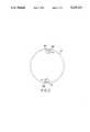
- FIG. 1is an illustrative schematic drawing of the system of this invention
- FIG. 2is a cross sectional view of an embodiment of the input lines at the closed far end of the plenum.
- FIG. 3is schematic drawing of another embodiment of this invention.
- the electron beampasses into the transformation or detoxification plenum 17.
- the input end of the plenumis conical followed in this embodiment by a cylindrical section whose diameter is smaller than the electron beam.
- the optimum cone angle of the plenum for process efficiencyis designed so that the scatter angle of the electron beam entering the plenum will approximately conform to the plenum cone so that most of the electron beam is directed into the plenum to interact with gases being processed.
- Design of the chambershould be such that the accelerator window and plenum windows are positioned as close as practical. This results in a composite electron beam scatter angle from the two windows which is as narrow as possible. Smaller plenum cone angles may be required to meet practical constraints of size and weight, particularly for transportable systems. Also the length of the plenum should be optimized for beam energy and the density of the gas being detoxified. As with limitations on the cone angle, compromising overall length of the plenum for practical considerations of size and weight may be necessary. An overall length of about 20 feet seems to be a reasonable compromise between maximum efficiency and transportability.
- the pipesrun down the inside, along diametrically opposite sides of the plenum to its far end.
- An elbow 22 at the end of each input pipe(See FIG. 2) directs incoming gas initially into a vortex flow around the far end of the plenum.
- the input pipes 21(and if necessary additional interfering means not shown) are used to disrupt this flow pattern to create turbulence.
- the inputcould, of course, be fed from holes along the entry pipes 21.
- Turbulenceassures a uniform dose of electrons across the gas flowing through the plenum and increases the path length VOC molecules must travel.
- Treated gasexits through a pair of ports 23 near the electron beam input end of the plenum. Because that end is conical and grows smaller toward the point of input for the electron beam, no gas molecules escape exposure to an increasingly intense incoming electron beam.
- Additional lines 25can be added to allow the insertion of various catalysts into the plenum to aid in the reaction process. Electrons will undergo multiple scattering processes in the chamber, including collisions with other gas molecules and from collisions with the walls of the chamber. Interactions of primary scattered electrons with the VOCs result in chemical reactions which destroy the VOCs in the gas flow.
- the shape of the plenumis designed so that the upper or entrance portion of the plenum is conical.
- the cone angle of the plenumis fabricated to closely match the composite scatter angle of electrons entering the plenum. That angle follows from scatter created by windows such as the accelerator window and/or the plenum window. Length of the plenum depends on the energy of the electron beam and the density of the gas being processed.
- the range or distance electrons can travel through air when injected at 2.5 Mevis approximately 40 feet for 100% absorption. If however, one is interested in a transportable plenum, a 20 foot long plenum is more useful. Importantly, such a plenum if constructed in an appropriate configuration can achieve 32% efficiencies.
- the electron energy of a 2.5 Mev beam absorbed in 20 feet, or in approximately 1/2 the distance for full absorption,is approximately 2/3rds of the total. With such construction, one gives up or wastes 1/3rd the electron energy which becomes unavailable to destroy toxic molecules. Of the remaining 2/3rds, approximately 1/2 of the electrons will be lost or wasted through scatter and absorption in the chamber walls resulting in 32% efficiency.
- the shape of the chambermay also be used to control turbulence in the gas flow through the system. Desired dwell time will depend on such factors as the electron beam flux, plenum volume, the velocity with which the vapor moves through the system, the density of the vapors being treated as well as gas temperatures, and like elements.
- Desired dwell timewill depend on such factors as the electron beam flux, plenum volume, the velocity with which the vapor moves through the system, the density of the vapors being treated as well as gas temperatures, and like elements.
- One skilled in this artwill be able with a reasonable level of accuracy define and select the interrelated elements to create operable systems and systems with a controlled degree of efficiency within the teaching of this disclosure.
- the plenumcan be designed to be inserted vertically into a hole in the ground (see FIG. 3 below) which allows the earth surrounding the plenum to act as a radiation shield, reducing the shielding requirements in connection with the plenum.
- the plenumcan be oriented horizontally so that the accelerator module, plenum and a mobile shield can be mounted on a flatbed truck. Horizontal orientation is the preferred construction since transport from site to site is readily accomplished and deep holes to hold and shield the plenum at the clean-up site can be avoided.
- FIG. 3there is shown another embodiment of a system for the irradiation of vapor at atmospheric pressure.
- Plenum 31which is conical for its entire length may be operated buried in the ground with its axis vertically oriented. Shielding is achieved in such case by the surrounding earth.
- the accelerator 32 coupled to the plenumwas a 2.5 MeV electron accelerator which produced an average beam of 400 W.
- This systemusing a plenum design like that shown in FIG. 1, was successfully employed in actual field tests to expose trichlorethylene (TCE) vapor in a humid air stream to an electron dose of up to 500 kR. Excellent efficiency in destroying toxicity were reliably demonstrated. Good results, however, have also been obtained with electron doses as low as 90 kR
- VOCsenter the plenum through the vapor inputs 40 and 41 at the base.
- the vapornext passes through the plenum where it is exposed to an electron beam as it moves toward the vapor outlets 42 and 43 at the top of plenum 31.
- a sump 45 at the basecollects liquid condensate arising from the vapor's humidity. Liquid collected by the sump may then be sampled through sampling tube 46.
Landscapes
- Engineering & Computer Science (AREA)
- Chemical & Material Sciences (AREA)
- Chemical Kinetics & Catalysis (AREA)
- Health & Medical Sciences (AREA)
- Environmental & Geological Engineering (AREA)
- General Chemical & Material Sciences (AREA)
- Toxicology (AREA)
- Oil, Petroleum & Natural Gas (AREA)
- Physics & Mathematics (AREA)
- Analytical Chemistry (AREA)
- Soil Sciences (AREA)
- Life Sciences & Earth Sciences (AREA)
- Plasma & Fusion (AREA)
- General Health & Medical Sciences (AREA)
- Organic Chemistry (AREA)
- Thermal Sciences (AREA)
- Biomedical Technology (AREA)
- Business, Economics & Management (AREA)
- Emergency Management (AREA)
- Treating Waste Gases (AREA)
- Processing Of Solid Wastes (AREA)
- Fire-Extinguishing Compositions (AREA)
Abstract
Description
Claims (26)
Priority Applications (13)
| Application Number | Priority Date | Filing Date | Title |
|---|---|---|---|
| US07/941,788US5319211A (en) | 1992-09-08 | 1992-09-08 | Toxic remediation |
| US07/992,614US5357291A (en) | 1992-09-08 | 1992-12-18 | Transportable electron beam system and method |
| US08/062,964US5378898A (en) | 1992-09-08 | 1993-05-14 | Electron beam system |
| CA002144082ACA2144082C (en) | 1992-09-08 | 1993-08-11 | Toxic remediation system and method |
| DE69332409TDE69332409T2 (en) | 1992-09-08 | 1993-08-11 | SYSTEM AND METHOD FOR THE DISPOSAL OF TOXIC WASTE |
| EP93919953AEP0659297B1 (en) | 1992-09-08 | 1993-08-11 | Toxic remediation system and method |
| PCT/US1993/007518WO1994006149A1 (en) | 1992-09-08 | 1993-08-11 | Toxic remediation system and method |
| AU50042/93AAU5004293A (en) | 1992-09-08 | 1993-08-11 | Toxic remediation system and method |
| JP50719294AJP3578215B2 (en) | 1992-09-08 | 1993-08-11 | Apparatus and method for detoxifying toxic substances |
| US08/116,375US5457269A (en) | 1992-09-08 | 1993-09-03 | Oxidizing enhancement electron beam process and apparatus for contaminant treatment |
| US08/253,967US5539212A (en) | 1992-09-08 | 1994-06-03 | Toxic remediation system and method |
| US08/323,636US5744811A (en) | 1992-09-08 | 1994-10-17 | Transportable electron beam system and method |
| US08/360,372US5523577A (en) | 1992-09-08 | 1994-12-21 | Electron beam system |
Applications Claiming Priority (1)
| Application Number | Priority Date | Filing Date | Title |
|---|---|---|---|
| US07/941,788US5319211A (en) | 1992-09-08 | 1992-09-08 | Toxic remediation |
Related Child Applications (4)
| Application Number | Title | Priority Date | Filing Date |
|---|---|---|---|
| US07/992,614Continuation-In-PartUS5357291A (en) | 1992-09-08 | 1992-12-18 | Transportable electron beam system and method |
| US08/062,964Continuation-In-PartUS5378898A (en) | 1992-09-08 | 1993-05-14 | Electron beam system |
| US08/253,967ContinuationUS5539212A (en) | 1992-09-08 | 1994-06-03 | Toxic remediation system and method |
| US08/360,372Continuation-In-PartUS5523577A (en) | 1992-09-08 | 1994-12-21 | Electron beam system |
Publications (1)
| Publication Number | Publication Date |
|---|---|
| US5319211Atrue US5319211A (en) | 1994-06-07 |
Family
ID=25477064
Family Applications (2)
| Application Number | Title | Priority Date | Filing Date |
|---|---|---|---|
| US07/941,788Expired - LifetimeUS5319211A (en) | 1992-09-08 | 1992-09-08 | Toxic remediation |
| US08/253,967Expired - LifetimeUS5539212A (en) | 1992-09-08 | 1994-06-03 | Toxic remediation system and method |
Family Applications After (1)
| Application Number | Title | Priority Date | Filing Date |
|---|---|---|---|
| US08/253,967Expired - LifetimeUS5539212A (en) | 1992-09-08 | 1994-06-03 | Toxic remediation system and method |
Country Status (7)
| Country | Link |
|---|---|
| US (2) | US5319211A (en) |
| EP (1) | EP0659297B1 (en) |
| JP (1) | JP3578215B2 (en) |
| AU (1) | AU5004293A (en) |
| CA (1) | CA2144082C (en) |
| DE (1) | DE69332409T2 (en) |
| WO (1) | WO1994006149A1 (en) |
Cited By (22)
| Publication number | Priority date | Publication date | Assignee | Title |
|---|---|---|---|---|
| US5483074A (en)* | 1995-01-11 | 1996-01-09 | Litton Systems, Inc. | Flood beam electron gun |
| US5530255A (en)* | 1990-08-17 | 1996-06-25 | Raychem Corporation | Apparatus and methods for electron beam irradiation |
| US5621270A (en)* | 1995-03-22 | 1997-04-15 | Litton Systems, Inc. | Electron window for toxic remediation device with a support grid having diverging angle holes |
| US5623183A (en)* | 1995-03-22 | 1997-04-22 | Litton Systems, Inc. | Diverging beam electron gun for a toxic remediation device with a dome-shaped focusing electrode |
| WO1998007175A3 (en)* | 1996-08-13 | 1998-03-19 | Masahiro Izutsu | Electron-beam irradiation apparatus |
| US5744811A (en)* | 1992-09-08 | 1998-04-28 | Zapit Technology, Inc. | Transportable electron beam system and method |
| US5770785A (en)* | 1992-07-09 | 1998-06-23 | Kabushiki Kaisha Toshiba | Apparatus and method for removing carbon dioxide contained in exhaust gas |
| US6623706B2 (en) | 2000-06-20 | 2003-09-23 | Advanced Electron Beams, Inc. | Air sterilizing system |
| US6623705B2 (en) | 2000-06-20 | 2003-09-23 | Advanced Electron Beams, Inc. | Gas conversion system |
| US6696693B1 (en)* | 1999-07-02 | 2004-02-24 | Ebara Corporation | Electron beam irradiation apparatus and method |
| US6724003B1 (en)* | 1999-01-11 | 2004-04-20 | Ebara Corporation | Electron beam-irradiating reaction apparatus |
| US20040187243A1 (en)* | 1999-09-01 | 2004-09-30 | Diethard Trenz | Brush |
| US20060076507A1 (en)* | 2000-06-20 | 2006-04-13 | Advanced Electron Beams, Inc. | Air Sterilizing system |
| US20060113486A1 (en)* | 2004-11-26 | 2006-06-01 | Valence Corporation | Reaction chamber |
| US7148613B2 (en) | 2004-04-13 | 2006-12-12 | Valence Corporation | Source for energetic electrons |
| US20090205947A1 (en)* | 2005-02-10 | 2009-08-20 | John Barkanic | Method for the reduction of malodorous compounds |
| US7656236B2 (en) | 2007-05-15 | 2010-02-02 | Teledyne Wireless, Llc | Noise canceling technique for frequency synthesizer |
| US8179045B2 (en) | 2008-04-22 | 2012-05-15 | Teledyne Wireless, Llc | Slow wave structure having offset projections comprised of a metal-dielectric composite stack |
| CN102910701A (en)* | 2011-08-02 | 2013-02-06 | 克朗斯股份公司 | Thermal sterilisation of water |
| US9202660B2 (en) | 2013-03-13 | 2015-12-01 | Teledyne Wireless, Llc | Asymmetrical slow wave structures to eliminate backward wave oscillations in wideband traveling wave tubes |
| US20220396504A1 (en)* | 2019-07-09 | 2022-12-15 | Fermi Research Alliance, Llc | Water purification system |
| WO2025132534A1 (en)* | 2023-12-20 | 2025-06-26 | Commissariat A L'energie Atomique Et Aux Energies Alternatives | Method for purifying a gas |
Families Citing this family (9)
| Publication number | Priority date | Publication date | Assignee | Title |
|---|---|---|---|---|
| WO1996024805A1 (en)* | 1995-02-08 | 1996-08-15 | James Winchester | Process and device for destroying hazardous compounds in incinerator flue gas |
| JPH10216460A (en)* | 1997-01-31 | 1998-08-18 | Hitachi Ltd | Electron beam gas processing equipment |
| WO2002058742A1 (en) | 2000-12-13 | 2002-08-01 | Advanced Electron Beams, Inc. | Decontamination apparatus |
| US7183563B2 (en)* | 2000-12-13 | 2007-02-27 | Advanced Electron Beams, Inc. | Irradiation apparatus |
| JP2002336836A (en)* | 2001-05-14 | 2002-11-26 | Japan Atom Energy Res Inst | Device for purifying solids contaminated with dioxins and / or polychlorinated biphenyls |
| KR20030086907A (en)* | 2002-05-03 | 2003-11-12 | 김조천 | Hybrid apparatus and method for removing volatile organic compounds and odorous substances by electron beam and catalyst |
| KR100375833B1 (en)* | 2002-05-16 | 2003-03-12 | Boram E & T Co Ltd | Apparatus for eliminating volatile organic compounds using electronic beam and catalyst |
| JP2004098035A (en)* | 2002-09-13 | 2004-04-02 | Japan Atom Energy Res Inst | Decomposition method of dioxins in smoke and exhaust gas by electron beam irradiation |
| FR3006602B1 (en)* | 2013-06-10 | 2016-01-29 | Vivirad | DEVICE FOR TREATING AT LEAST ONE FLOW OF GASEOUS EFFLUENTS |
Citations (11)
| Publication number | Priority date | Publication date | Assignee | Title |
|---|---|---|---|---|
| US2892946A (en)* | 1955-11-25 | 1959-06-30 | High Voltage Engineering Corp | Method of and apparatus for the more efficient use of high-energy charged particles in the treatment of gasphase systems |
| US4294674A (en)* | 1978-12-29 | 1981-10-13 | Ebara Corporation | Method of treating waste gas by irradiation |
| US4372832A (en)* | 1981-01-21 | 1983-02-08 | Research-Cottrell, Incorporated | Pollution control by spray dryer and electron beam treatment |
| US4507265A (en)* | 1978-12-29 | 1985-03-26 | Ebara Corporation | Apparatus for treating effluent gas by irradiation with electron beams |
| US4595569A (en)* | 1984-02-03 | 1986-06-17 | Polymer-Physik Gmbh & Co. Kg | Device for desulphurizing and denitrating flue gases by electron irradiation |
| US4702808A (en)* | 1957-06-27 | 1987-10-27 | Lemelson Jerome H | Chemical reaction apparatus and method |
| US4752450A (en)* | 1985-07-11 | 1988-06-21 | Leybold-Heraeus Gmbh | Apparatus for cleaning sulphur and nitrogen containing flue gas |
| US4882020A (en)* | 1987-05-30 | 1989-11-21 | Ebara Corporation | Process for treating effluent gas |
| US4915916A (en)* | 1986-04-24 | 1990-04-10 | Ebara Corporation | Method of and apparatus for treating waste gas by irradiation with electron beam |
| US4969984A (en)* | 1987-06-01 | 1990-11-13 | Ebara Corporation | Exhaust gas treatment process using irradiation |
| US5219534A (en)* | 1991-04-26 | 1993-06-15 | Reynolds Warren D | Process and apparatus for decontaminating air |
Family Cites Families (9)
| Publication number | Priority date | Publication date | Assignee | Title |
|---|---|---|---|---|
| US2583899A (en)* | 1950-11-29 | 1952-01-29 | Lester H Smith | Electrochemical process |
| US2958638A (en)* | 1958-04-24 | 1960-11-01 | Exxon Research Engineering Co | Reaction container for carrying out radiation induced chemical reactions |
| JPS5940051B2 (en)* | 1979-07-11 | 1984-09-27 | 株式会社荏原製作所 | Electron beam irradiation exhaust gas treatment equipment |
| SU1134548A2 (en)* | 1983-08-23 | 1985-01-15 | Предприятие П/Я Р-6601 | Apparatus for neutralizing waste liquors |
| DE3513633C2 (en)* | 1985-04-16 | 1994-06-16 | Polymer Physik Gmbh | Device for the desulphurization and denitrification of flue gases by electron radiation |
| DE3620673A1 (en)* | 1985-10-23 | 1987-12-23 | Licentia Gmbh | METHOD FOR IRRADIATING GAS-SHAPED MEDIA, PREFERABLY SMOKE GASES, WITH ELECTRON BEAMS |
| DE3761531D1 (en)* | 1986-05-30 | 1990-03-08 | Noell Gmbh | METHOD AND DEVICE FOR SIMULTANEOUS SEPARATION OF SULFUR DIOXIDE AND NITROGEN. |
| EP0540756B1 (en)* | 1991-05-21 | 1997-01-02 | Institute Of Nuclear Chemistry And Technology | A PROCESS FOR REMOVAL OF SO 2? AND NO x? FROM COMBUSTION FLUE GASES AND AN APPARATUS USED THEREFOR |
| US5357291A (en)* | 1992-09-08 | 1994-10-18 | Zapit Technology, Inc. | Transportable electron beam system and method |
- 1992
- 1992-09-08USUS07/941,788patent/US5319211A/ennot_activeExpired - Lifetime
- 1993
- 1993-08-11DEDE69332409Tpatent/DE69332409T2/ennot_activeExpired - Fee Related
- 1993-08-11EPEP93919953Apatent/EP0659297B1/ennot_activeExpired - Lifetime
- 1993-08-11CACA002144082Apatent/CA2144082C/ennot_activeExpired - Fee Related
- 1993-08-11JPJP50719294Apatent/JP3578215B2/ennot_activeExpired - Fee Related
- 1993-08-11WOPCT/US1993/007518patent/WO1994006149A1/enactiveIP Right Grant
- 1993-08-11AUAU50042/93Apatent/AU5004293A/ennot_activeAbandoned
- 1994
- 1994-06-03USUS08/253,967patent/US5539212A/ennot_activeExpired - Lifetime
Patent Citations (13)
| Publication number | Priority date | Publication date | Assignee | Title |
|---|---|---|---|---|
| US2892946A (en)* | 1955-11-25 | 1959-06-30 | High Voltage Engineering Corp | Method of and apparatus for the more efficient use of high-energy charged particles in the treatment of gasphase systems |
| US4702808A (en)* | 1957-06-27 | 1987-10-27 | Lemelson Jerome H | Chemical reaction apparatus and method |
| US4507265A (en)* | 1978-12-29 | 1985-03-26 | Ebara Corporation | Apparatus for treating effluent gas by irradiation with electron beams |
| US4596642A (en)* | 1978-12-29 | 1986-06-24 | Ebara Corporation | Process and apparatus for treating effluent gas by irradiation with electron beams |
| US4294674A (en)* | 1978-12-29 | 1981-10-13 | Ebara Corporation | Method of treating waste gas by irradiation |
| US4372832A (en)* | 1981-01-21 | 1983-02-08 | Research-Cottrell, Incorporated | Pollution control by spray dryer and electron beam treatment |
| US4595569A (en)* | 1984-02-03 | 1986-06-17 | Polymer-Physik Gmbh & Co. Kg | Device for desulphurizing and denitrating flue gases by electron irradiation |
| US4752450A (en)* | 1985-07-11 | 1988-06-21 | Leybold-Heraeus Gmbh | Apparatus for cleaning sulphur and nitrogen containing flue gas |
| US4915916A (en)* | 1986-04-24 | 1990-04-10 | Ebara Corporation | Method of and apparatus for treating waste gas by irradiation with electron beam |
| US5015443A (en)* | 1986-04-24 | 1991-05-14 | Ebara Corporation | Method of and apparatus for treating waste gas by irradiation with electron beam |
| US4882020A (en)* | 1987-05-30 | 1989-11-21 | Ebara Corporation | Process for treating effluent gas |
| US4969984A (en)* | 1987-06-01 | 1990-11-13 | Ebara Corporation | Exhaust gas treatment process using irradiation |
| US5219534A (en)* | 1991-04-26 | 1993-06-15 | Reynolds Warren D | Process and apparatus for decontaminating air |
Cited By (29)
| Publication number | Priority date | Publication date | Assignee | Title |
|---|---|---|---|---|
| US5530255A (en)* | 1990-08-17 | 1996-06-25 | Raychem Corporation | Apparatus and methods for electron beam irradiation |
| US5770785A (en)* | 1992-07-09 | 1998-06-23 | Kabushiki Kaisha Toshiba | Apparatus and method for removing carbon dioxide contained in exhaust gas |
| US5744811A (en)* | 1992-09-08 | 1998-04-28 | Zapit Technology, Inc. | Transportable electron beam system and method |
| US5483074A (en)* | 1995-01-11 | 1996-01-09 | Litton Systems, Inc. | Flood beam electron gun |
| US5621270A (en)* | 1995-03-22 | 1997-04-15 | Litton Systems, Inc. | Electron window for toxic remediation device with a support grid having diverging angle holes |
| US5623183A (en)* | 1995-03-22 | 1997-04-22 | Litton Systems, Inc. | Diverging beam electron gun for a toxic remediation device with a dome-shaped focusing electrode |
| WO1998007175A3 (en)* | 1996-08-13 | 1998-03-19 | Masahiro Izutsu | Electron-beam irradiation apparatus |
| US6724003B1 (en)* | 1999-01-11 | 2004-04-20 | Ebara Corporation | Electron beam-irradiating reaction apparatus |
| US6696693B1 (en)* | 1999-07-02 | 2004-02-24 | Ebara Corporation | Electron beam irradiation apparatus and method |
| US20040187243A1 (en)* | 1999-09-01 | 2004-09-30 | Diethard Trenz | Brush |
| US20060076507A1 (en)* | 2000-06-20 | 2006-04-13 | Advanced Electron Beams, Inc. | Air Sterilizing system |
| US7547892B2 (en) | 2000-06-20 | 2009-06-16 | Advanced Electron Beams, Inc. | Air sterilizing system |
| US20040057883A1 (en)* | 2000-06-20 | 2004-03-25 | Advanced Electron Beams, Inc. | Gas conversion system |
| US6623705B2 (en) | 2000-06-20 | 2003-09-23 | Advanced Electron Beams, Inc. | Gas conversion system |
| US6623706B2 (en) | 2000-06-20 | 2003-09-23 | Advanced Electron Beams, Inc. | Air sterilizing system |
| US20040060811A1 (en)* | 2000-06-20 | 2004-04-01 | Tzvi Avnery | Air sterilizing system |
| US7189978B2 (en) | 2000-06-20 | 2007-03-13 | Advanced Electron Beams, Inc. | Air sterilizing system |
| US20070145291A1 (en)* | 2000-06-20 | 2007-06-28 | Tzvi Avnery | Air sterilizing system |
| US7323137B2 (en) | 2000-06-20 | 2008-01-29 | Advanced Electron Beams, Inc. | Air sterilizing system |
| US7148613B2 (en) | 2004-04-13 | 2006-12-12 | Valence Corporation | Source for energetic electrons |
| US20060113486A1 (en)* | 2004-11-26 | 2006-06-01 | Valence Corporation | Reaction chamber |
| US20090205947A1 (en)* | 2005-02-10 | 2009-08-20 | John Barkanic | Method for the reduction of malodorous compounds |
| US7656236B2 (en) | 2007-05-15 | 2010-02-02 | Teledyne Wireless, Llc | Noise canceling technique for frequency synthesizer |
| US8179045B2 (en) | 2008-04-22 | 2012-05-15 | Teledyne Wireless, Llc | Slow wave structure having offset projections comprised of a metal-dielectric composite stack |
| CN102910701A (en)* | 2011-08-02 | 2013-02-06 | 克朗斯股份公司 | Thermal sterilisation of water |
| US9202660B2 (en) | 2013-03-13 | 2015-12-01 | Teledyne Wireless, Llc | Asymmetrical slow wave structures to eliminate backward wave oscillations in wideband traveling wave tubes |
| US20220396504A1 (en)* | 2019-07-09 | 2022-12-15 | Fermi Research Alliance, Llc | Water purification system |
| WO2025132534A1 (en)* | 2023-12-20 | 2025-06-26 | Commissariat A L'energie Atomique Et Aux Energies Alternatives | Method for purifying a gas |
| FR3157220A1 (en)* | 2023-12-20 | 2025-06-27 | Commissariat A L'energie Atomique Et Aux Energies Alternatives | Process for purifying a gas |
Also Published As
| Publication number | Publication date |
|---|---|
| JPH08504123A (en) | 1996-05-07 |
| EP0659297A4 (en) | 1998-12-09 |
| US5539212A (en) | 1996-07-23 |
| EP0659297B1 (en) | 2002-10-16 |
| AU5004293A (en) | 1994-03-29 |
| WO1994006149A1 (en) | 1994-03-17 |
| EP0659297A1 (en) | 1995-06-28 |
| CA2144082A1 (en) | 1994-03-17 |
| DE69332409D1 (en) | 2002-11-21 |
| CA2144082C (en) | 1999-10-12 |
| DE69332409T2 (en) | 2003-06-18 |
| JP3578215B2 (en) | 2004-10-20 |
Similar Documents
| Publication | Publication Date | Title |
|---|---|---|
| US5319211A (en) | Toxic remediation | |
| US5357291A (en) | Transportable electron beam system and method | |
| JP3519408B2 (en) | Processing unit, processing system, and electron beam source used for converting and processing volatile organic compounds using electrons | |
| CA1225441A (en) | Plasma pyrolysis waste destruction | |
| WO1995006619A1 (en) | Oxidizing enhancement electron beam process and apparatus for contaminant treatment | |
| US6534754B2 (en) | Microwave off-gas treatment apparatus and process | |
| Zheng et al. | Destruction of PCDD/Fs by gliding arc discharges | |
| US5126020A (en) | Detoxification apparatus and method for toxic waste using an energy beam and electrolysis | |
| CA1286918C (en) | Incineration system for the destruction of hazardous wastes | |
| CA2417346A1 (en) | Odor control through air-facilitated injection of hydroxyl radicals | |
| US5807491A (en) | Electron beam process and apparatus for the treatment of an organically contaminated inorganic liquid or gas | |
| Hilarides et al. | Feasibility, system design, and economic evaluation of radiolytic degradation of 2, 3, 7, 8‐tetrachlorodibenzo‐p‐dioxin on soil | |
| George et al. | Soil decontamination via microwave and radio frequency co‐volatilization | |
| Hadidi et al. | Economic study of the tunable electron beam plasma reactor for volatile organic compound treatment | |
| WO1994017899A1 (en) | Tunable compact electron beam generated plasma system for the destruction of gaseous toxic compounds | |
| Gray et al. | Environmental radiolysis for soil and sediment treatment: a review of chemistry, design, and economic issues | |
| Matthews et al. | Radiolytic decomposition of environmental contaminants and site remediation using an electron accelerator | |
| KR20040010902A (en) | Purification apparatus and method for flushing water/extracted gas of contaminated soil and/or contaminated groundwater by electron beam irradiation | |
| DANIEL | Processing of Waste | |
| Anshumali et al. | Destruction of low levels of volatile organic compounds in dry air streams by an electron-beam generated plasma | |
| Tak et al. | Pulsed corona plasma pilot plant for VOC abatement in industrial streams as mobile and educational laboratory | |
| Rosocha et al. | Short-pulsed, electric-discharge degradation of toxic and sludge wastes | |
| Abdelaziz | Treatment of Municipal and Industrial Waste by Radiation Processing | |
| Rosocha et al. | REPORT DOCUMENTATION PAGE yTSTT | |
| Peters | Use of sonication for in-well softening of semivolatile organic compounds |
Legal Events
| Date | Code | Title | Description |
|---|---|---|---|
| AS | Assignment | Owner name:SCHONBERG RADIATION CORP., CALIFORNIA Free format text:ASSIGNMENT OF ASSIGNORS INTEREST;ASSIGNOR:SCHONBERG, RUSSELL GEORGE;REEL/FRAME:006822/0921 Effective date:19920918 Owner name:SCHONBERG RADIATION CORP., CALIFORNIA Free format text:ASSIGNMENT OF ASSIGNORS INTEREST;ASSIGNOR:FADNESS, DAVID RICHARD;REEL/FRAME:006822/0924 Effective date:19921022 | |
| AS | Assignment | Owner name:REGENTS OF THE UNIVERISTY OF CALIFORNIA, CALIFORNI Free format text:ASSIGNMENT OF ASSIGNORS INTEREST;ASSIGNOR:MATTHEWS, STEPHEN M.;REEL/FRAME:006898/0803 Effective date:19940309 | |
| STCF | Information on status: patent grant | Free format text:PATENTED CASE | |
| FPAY | Fee payment | Year of fee payment:4 | |
| SULP | Surcharge for late payment | ||
| AS | Assignment | Owner name:ENERGY, UNITED STATES DEPARTMENT OF, DISTRICT OF C Free format text:CONFIRMATORY LICENSE;ASSIGNOR:CALIFORNIA, UNIVERSITY OF;REEL/FRAME:009453/0385 Effective date:19970815 | |
| AS | Assignment | Owner name:TIPAZ INCORPORATED, TEXAS Free format text:CHANGE OF NAME;ASSIGNOR:SCHONBERG RESEARCH CORORATION BY CHANGE OF NAME FROM SCHONBERG RADIATION CORD A CORPORATION UNDER THE LAWS OF THE STATE OF CA;REEL/FRAME:012103/0371 Effective date:20010619 | |
| FPAY | Fee payment | Year of fee payment:8 | |
| REMI | Maintenance fee reminder mailed | ||
| AS | Assignment | Owner name:VALENCE CORPORATION, ARKANSAS Free format text:CHANGE OF NAME;ASSIGNOR:TIPAZ INCORPORATED;REEL/FRAME:015177/0403 Effective date:20040512 | |
| FPAY | Fee payment | Year of fee payment:12 | |
| AS | Assignment | Owner name:LAWRENCE LIVERMORE NATIONAL SECURITY, LLC, CALIFOR Free format text:ASSIGNMENT 50% UNDIVIDED INTEREST;ASSIGNOR:REGENTS OF THE UNIVERSITY OF CALIFORNIA, THE;REEL/FRAME:020010/0398 Effective date:20070924 |