US5318596A - Activity sensing pacemaker - Google Patents
Activity sensing pacemakerDownload PDFInfo
- Publication number
- US5318596A US5318596AUS07/791,423US79142391AUS5318596AUS 5318596 AUS5318596 AUS 5318596AUS 79142391 AUS79142391 AUS 79142391AUS 5318596 AUS5318596 AUS 5318596A
- Authority
- US
- United States
- Prior art keywords
- axis
- pacemaker
- sensing
- activity
- coupled
- Prior art date
- Legal status (The legal status is an assumption and is not a legal conclusion. Google has not performed a legal analysis and makes no representation as to the accuracy of the status listed.)
- Expired - Lifetime
Links
- 230000000694effectsEffects0.000titleclaimsabstractdescription101
- 230000033001locomotionEffects0.000claimsabstractdescription71
- 230000004044responseEffects0.000claimsabstractdescription15
- 239000003990capacitorSubstances0.000claimsdescription36
- 230000000747cardiac effectEffects0.000claimsdescription10
- 230000005669field effectEffects0.000claimsdescription2
- 230000005484gravityEffects0.000claimsdescription2
- 230000033764rhythmic processEffects0.000claimsdescription2
- 239000004020conductorSubstances0.000claims2
- 230000037081physical activityEffects0.000description12
- 239000002033PVDF binderSubstances0.000description8
- 230000001276controlling effectEffects0.000description8
- 229920002981polyvinylidene fluoridePolymers0.000description8
- 235000014676Phragmites communisNutrition0.000description6
- 238000010586diagramMethods0.000description5
- 239000000463materialSubstances0.000description5
- QSHDDOUJBYECFT-UHFFFAOYSA-NmercuryChemical compound[Hg]QSHDDOUJBYECFT-UHFFFAOYSA-N0.000description4
- 229910052753mercuryInorganic materials0.000description4
- 230000000284resting effectEffects0.000description4
- 244000273256Phragmites communisSpecies0.000description3
- 230000001133accelerationEffects0.000description3
- 230000008859changeEffects0.000description3
- 229920000131polyvinylidenePolymers0.000description3
- 238000010276constructionMethods0.000description2
- 238000006073displacement reactionMethods0.000description2
- 230000006870functionEffects0.000description2
- 229920000642polymerPolymers0.000description2
- 102100026827Protein associated with UVRAG as autophagy enhancerHuman genes0.000description1
- 101710102978Protein associated with UVRAG as autophagy enhancerProteins0.000description1
- 229910000639Spring steelInorganic materials0.000description1
- 230000000903blocking effectEffects0.000description1
- 230000015556catabolic processEffects0.000description1
- 230000001419dependent effectEffects0.000description1
- 238000001514detection methodMethods0.000description1
- 238000007599dischargingMethods0.000description1
- 230000005684electric fieldEffects0.000description1
- 238000000034methodMethods0.000description1
- 238000012986modificationMethods0.000description1
- 230000004048modificationEffects0.000description1
- 239000004033plasticSubstances0.000description1
- 229920003023plasticPolymers0.000description1
- 230000008569processEffects0.000description1
- 239000011253protective coatingSubstances0.000description1
- 230000009467reductionEffects0.000description1
- 230000036279refractory periodEffects0.000description1
- 230000001105regulatory effectEffects0.000description1
- 230000000630rising effectEffects0.000description1
- 230000035945sensitivityEffects0.000description1
- 230000000638stimulationEffects0.000description1
- 230000009182swimmingEffects0.000description1
Images

Classifications
- A—HUMAN NECESSITIES
- A61—MEDICAL OR VETERINARY SCIENCE; HYGIENE
- A61N—ELECTROTHERAPY; MAGNETOTHERAPY; RADIATION THERAPY; ULTRASOUND THERAPY
- A61N1/00—Electrotherapy; Circuits therefor
- A61N1/18—Applying electric currents by contact electrodes
- A61N1/32—Applying electric currents by contact electrodes alternating or intermittent currents
- A61N1/36—Applying electric currents by contact electrodes alternating or intermittent currents for stimulation
- A61N1/362—Heart stimulators
- A61N1/365—Heart stimulators controlled by a physiological parameter, e.g. heart potential
- A61N1/36514—Heart stimulators controlled by a physiological parameter, e.g. heart potential controlled by a physiological quantity other than heart potential, e.g. blood pressure
- A61N1/36542—Heart stimulators controlled by a physiological parameter, e.g. heart potential controlled by a physiological quantity other than heart potential, e.g. blood pressure controlled by body motion, e.g. acceleration
Definitions
- the present inventionrelates to an activity sensing pacemaker which senses activity or motion along several different axes, such as the X axis, the Y axis and the Z axis, utilizing an array of motion sensors or acceleratometers and to pulse generating circuitry for controlling the output of heart stimulus pulses relative to the level of activity sensed.
- the Dahl U.S. Pat. No. 4,140,132discloses a variable rate timer for a cardiac pacemaker including a piezoelectric element, a rectifier for rectifying the signals generated by the piezoelectric element and a capacitor network which receives the rectified pulses from the rectifier and stores those pulses therein.
- the stored pulsesare supplied to the gate of a field effect transistor where a level or charge of voltage stored controls the current to the transistor which is used to control the pacing or timing rate of the pacemaker.
- the activity sensing pacemaker of the present inventiondiffers from the Dahl patent by sensing activity or motion along several different axes, preferably three axes, and does not rectify voltage generated by a piezoelectric element and does not have a voltage circuit including a constant timing resistor or a timing capacitor.
- the Anderson U.S. Pat. No. 4,428,378teaches a motion sensor that supplies signals to a level detector and band pass amplifier so that pulses above a certain level and within a certain frequency band only, are integrated to provide a control signal for controlling pacing.
- the Sholder U.S. Pat. No. 4,771,780teaches an activity sensor comprising a moving conducting element within a housing, as does the Lekholm et al. U.S. Pat. No. 4,869,251.
- Lekholm et al.there is provided a hollow member with a freely movable member therein, the freely movable member generating a mechanical vibration upon movement by a patient.
- a transducersenses the vibration and generates an electrical signal corresponding to the mechanical vibrations.
- the electrical signalis proportionate to the movement and is used to vary the stimulation rate.
- the moving conducting element within the cylindrical housingmakes and breaks electrical contacts between at least two of a plurality of electrodes in the housing, the making and breaking of contacts being indicative of motion or activity of the patient.
- the Alt U.S. Pat. No. 4,846,195discloses an implantable position and motion sensor which includes a housing having a circular disc-like wall of electrically insulative material with conductive pins extending therethrough, a lid portion over the circular disc-like wall and a mercury ball within the housing and movable between the pins for effecting conduction between the pins. Movement of the mercury ball between the pins and the lid portion will generate signals indicating activity or movement of the patient and the position of the mercury ball indicates whether the patient is standing or lying down.
- the Nilsson U.S. Pat. No. 4,896,068teaches the construction of an activity sensor having two individual or inter-related piezoceramic parts arranged side by side which are oppositely polarized and which are secured to a flat wall of a pacemaker housing.
- the Stotts U.S. Pat. No. 4,913,145discloses a cardiac pacemaker which has a sense amplifier for passing signal components lying in a selectively variable pass band.
- the Alt U.S. Pat. No. 4,926,863teaches the use of an accelerometer in a rate responsive cardiac pacemaker for sensing body movement and then selects only a portion of the electrical signal generated by the accelerometer at a frequency rate below 4 Hz to discriminate against signal components arising from other than physical exercise of the patient.
- the Mann et al. U.S. Pat. No. 4,940,052discloses a processor in a pacemaker which converts a raw signal generated by an activity sensor (a piezoelectric sensor) to a sensor-indicator rate signal in accordance with a selectable transfer relationship which defines the sensor-indicator rate signals as a function of a set of discrete sensor level index signals.
- the selected sensor level index signalsis related to the energy content of the raw signal.
- the selective sensor level index signalis used to control the pacing rate from a pulse generator.
- the Mann et al. U.S. Pat. No. 4,940,053discloses a rate responsive pacemaker having a piezoelectric sensor and a raw signal energy converter which amplifies the raw signal, rectifies the raw signal and then integrates the area of the raw signal in one embodiment of the energy converter.
- the durations of each rectified pulse of the raw signalsare counted, individual duration counts are summed over a period of time (integrated) and the sum is utilized as an indication of the energy content of the raw signal.
- the level of the energy contentis used to control the pacing rate of a pacemaker.
- the Sholder U.S. Pat. No. 5,010,893discloses a motion sensor mounted in a pacemaker.
- the motion sensorincludes an enclosed housing having a movable conductive element therein that partially fills the space in the housing and is free to flow or otherwise move around the inside of the housing in response to external forces.
- the conductive elementmoves within the enclosed housing, it makes electrical contact with at least two of three electrodes that are selectively spaced around the periphery of the housing in a manner similar to the movement of a contact in the earlier Sholder patent and the mercury ball in the earlier Alt patent.
- an activity sensing pacemakercomprising: a heart pulse sensing device for sensing heart pulses; pulse generating circuitry for generating pacing pulses; activity sensing structure and circuitry for sensing body movements of a patient wearing the pacemaker relative to the chest of the patient in specific ones of three dimensions or directions extending along an x axis, a y axis, or a z axis, and independent of the force of gravity, the activity sensing structure and circuitry including first structure for sensing activity along a first one of the three axes and second structure for sensing activity along a second one of the three axes; and, control circuitry coupled to the heart pulse sensing device, to the pulse generating circuitry and to the activity sensing structure and circuitry for controlling the pacing frequency of the pacing pulses generated by the pulse generating circuitry either in response to the intrinsic heart rhythm of the patient sensed by the heart pulse sensing device or in response to the direction and frequency of the patient's body motions sensed by the activity
- the control circuitrycontrols a pulse generator relative to the frequency of pulse signals from the activity sensing devices and circuitry independent of the amplitude or duration of the pulse signals.
- the control circuitryincludes programming in a program memory and a multivibrator (a) for enabling the multivibrator to pass only signals received relative to the activity/movement along one, two and/or three of the axes along which activity/movement is sensed and/or (b) for requiring that there be signals on all three axes in order for there to be output pulses at the output of the monostable multivibrator.
- an activity sensing pacemakercomprising: a heart pulse sensing device for sensing heart pulses; pulse generating circuitry for generating pacing pulses; activity sensing structure and circuitry for sensing activity/movement of a patient wearing the pacemaker in one or more of three directions/dimensions, x, y, z, and for causing the pulse generating circuitry to generate pacing pulses at a rate/frequency related to the movements sensed; and, control circuitry coupled to the heart pulse sensing device, to the pulse generating circuitry and to the activity sensing structure and circuitry for controlling the pulse generating circuitry in response to the heart pulses sensed or in response to the patient movements sensed, the activity sensing structure and circuitry causing generation of control pulses related to the movements of the patient and the control circuitry including frequency sensing circuitry for sensing the frequency of the control pulses generated and for controlling the rate/frequency of the pacing pulses generated by the pulse generating circuitry relative to the frequency of the control pulses generated by the movements
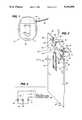
- FIG. 1is a side elevational view of a pacemaker having mounted therein applicant's activity sensor.
- FIG. 2is a perspective view of one embodiment of the activity sensor constructed according to the teachings of the present invention and shows a plate with three piezoelectric sensors for sensing activity along three different axis, the X axis, the Y axis and the Z axis.
- FIG. 3is a simplified schematic circuit diagram of the output from the piezoelectric sensors of the activity sensor shown in FIG. 2.
- FIG. 4is a perspective view of another embodiment of an activity sensor constructed according to the teachings of the present invention which comprises two parallel spaced plates with two piezoelectric sensors mounted between the plates for sensing activity along two different axes, e.g. the X axis and the Y axis and a piezoelectric sensor mounted along in the X-Y plane for sensing activity along the Z axis.
- two piezoelectric sensorsmounted between the plates for sensing activity along two different axes, e.g. the X axis and the Y axis and a piezoelectric sensor mounted along in the X-Y plane for sensing activity along the Z axis.
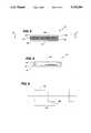
- FIG. 5is a longitudinal sectional view of a piezoelectric film which can be used as part of one of the piezoelectric sensors shown in FIG'S. 2 or 4.
- FIG. 6is a top plan view of the piezoelectric film shown in FIG. 5.
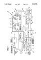
- FIG. 7is a schematic circuit diagram of the activity sensor processing and pulse generating circuitry which processes and utilizes the signals from the piezoelectric sensors for controlling the generation of pacing pulses.
- FIG. 8is a timing diagram of the signals at five different points in the circuitry shown in FIG. 7.
- FIG. 9is a graph of a cycle of the output signal from a bistable oscillator in the circuitry shown in FIG. 7.
- FIG. 1a cardiac pacemaker 10 comprising a lower case or can 12, and an upper top or neck 14 which receives the proximal end portion 16 of a pacing lead 18.
- an activity sensor 20constructed according to the teachings of the present invention.
- the activity sensor 20comprises a plate 22 having a hole 24 therein.
- the plateis non-metallic, typically a printed circuit board, and has a top edge 28 and a right side edge 30 joining at an upper right hand corner 32 of the plate 22.
- a cantilevered piezoelectric sensor 34is mounted on the plate adjacent the hole 24. This piezoelectric sensor 34 is cantilevered over the first hole 24 and will vibrate when the plate 22 is moved along the Z axis of the plate 22.
- the plate 22has along the right side edge 30 thereof a notch 36 near the upper right hand corner 32 and a portion 38 of the plate 22 adjacent the notch 36 supports a base leg 40 of a piezoelectric sensor 42 which has a bent outer leg 44 which extends outwardly from the plate 22 and is positioned to be moved or vibrated when there is movement along the X axis of the plate 22, as shown in FIG. 2.
- notch 46 and a portion 48 of the plate 22 adjacent that notch 46supports a base leg 50 of another piezoelectric sensor 52 which has an outer leg 54 which extends outwardly from the plate 22 and at a right angle to the piezoelectric sensor 34 and from the outwardly extending leg 44 of the piezoelectric sensor 42, and is positioned to vibrate when there is movement along the Y axis of the plate 22, as shown in FIG. 2.
- each piezoelectric sensoris connected to a ground or common 58 for a pacemaker system, such ground being a conductive strip 58 on a printed circuit on the plate 22.
- the signals produced from each of the piezoelectric sensors 42, 52 and 34are referred to as signals generated either along the X axis, the Y axis or the Z axis and are supplied to rate control circuitry 60 which will be described in greater detail in connection with the description of FIG. 7.
- FIG. 3shows the connection of each of the piezoelectric sensors 42, 52 and 34 to ground or common 58 and shows the output signals identified as X, Y and Z which are supplied to the circuitry 60 shown in FIG. 7.
- the activity sensor 20 shown in FIG. 3can be referred to as a tri-axial reed activity sensor comprising three sensors or reeds 42, 52 and 34 with a PVDF piezofilm bonded along its longitudinal plane and mechanically held at only one end to allow the other end to flex or vibrate freely.
- a reed sensoris shown in FIG'S. 5 and 6.
- the reeds 42, 52 and 34can be made from many materials having memory, such as spring steel and some plastics. Each reed 42, 52 or 34 is oriented in a different axis in order to sense motion in the X, Y or Z axis as described above.
- FIG'S. 5 and 6An example of the construction of one embodiment of the piezoelectric sensor 34 is shown in FIG'S. 5 and 6.
- a piezofilm 61has metalized upper and lower conductive films 62 and 63 thereon terminating at one end in electrode tabs 64 and 65.
- the conductive films 62 and 63each have an outer protective coating 66 or 67.
- the reeds 42, 52 and 34will flex, stretching the piezofilm which generates an electrical signal whose intensity corresponds to displacement acceleration forces induced by the patient.
- These electrical signalsare processed and converted into a pacing rate by the circuitry 60 shown in FIG. 7.
- FIG. 4there is illustrated another embodiment of an activity sensor 70 constructed according to the teachings of the present invention.
- the activity sensor 70comprises two spaced apart plates 72 and 74 with the upper plate 72 being substantially identical to the lower plate 74, each plate 72, 74 having a hole 76 and two notches 80 and 82.
- the plates 72, 74are held in a spaced apart relationship by four corner pins 84.
- Extending across the hole 76is a first piezoelectric sensor 86 which is made of a polyvinylidene film 87 having a weight 88 in the middle thereof, such as a ball bearing. This piezoelectric sensor 86 senses movement along the Z axis.
- a film 89 of piezoelectric polyvinylidene film supported between two base tabs 90 and 92 extending between the notches 80 and having a weight 94, such as a ball bearing, in the middle thereofdefines a second piezoelectric sensor 96.
- This piezoelectric sensor 96senses movement along the X axis.
- the notches 80 and 82allow the piezoelectric sensors 96 and 106 to be recessed within the rectangular edges of the plates 72 and 74.
- FIG. 4illustrates another tri-axial activity sensor 70 comprising three piezoelectric sensors 86, 96 and 104 defined by three strips 87, 89 and 97 of PVDF piezofilm, with a heavy object 88, 94 and 102, such as a ball bearing, bonded at the center, mechanically held at both ends in order to allow the center portion of the film 87, 89 and 97 to flex freely.
- a heavy object 88, 94 and 102such as a ball bearing
- Each piezofilm strip 87, 89, 97is oriented in a different axis in order to sense motions in the Z, X and Y axes and has one electrode tab thereof connected to a system ground or common 58 and another electrode tab connected to an input line 107, 108 or 109 to the circuitry 60 shown in FIG. 7.
- the piezofilm(s) 88, 94 and 102will stretch generating electrical signals whose intensity corresponds to the displacement and acceleration forces induced by the patient. Again, these electrical signals are processed and converted into a pacing rate by the circuitry 60 shown in FIG. 7.
- PVDF piezofilmPolyvinylidene fluoride (PVDF) piezofilm is used as an example of a material having required piezoelectric properties for use in the activity sensors 20 and 70 of the present invention.
- the activity sensors 20 and 70 of the present inventionare not to be limited to the use of PVDF piezofilm.
- Other piezoelementsmay be used including polymeric ferro-electric and bimorph type of sensors.
- PVDF piezofilmshould be considered as a dynamic material that develops an electrical charge proportional to changes in mechanical stress or strain. External forces applied to the film results in compressive or tensile strain and the film develops a proportionate open circuit voltage. Exposure to a reciprocating force results in a corresponding alternating electrical signal. The frequency response ranges widely--0.005 Hertz to gigaHertz.
- the piezoelectric properties of PVDFdepend heavily on the degree and type of its crystalline structure. Three common crystalline phases for the material are designated: alpha, beta and gamma. To obtain significant piezoelectric activity, beta phase polymer must be "poled". Poling exposes the polymer to a high electric field at elevated temperatures.
- the activity sensors 20 and 70sense activity or motion in three different axes, e.g. the X axis, the Y axis and the Z axis
- the activity sensor 20 or 70can be constructed to sense activity or motion in different axes other than the three axes indicated.
- two or more piezoelectric sensorscan be mounted on each axis along which motion is to be detected within the pacemaker housing and separate from the wall of the housing and in position to generate electrical signals when the pacemaker wearer engages in physical exercise, such as running or swimming.
- Each small voltage signal generated by one of the piezoelectric sensors 34, 42 and 52 or 86, 96 and 104is supplied through a multiplex switch 110, 111 and 112 in each of the input lines 107, 108 or 109 to a programmable monostable multivibrator 114, as shown in FIG. 7.
- the monostable multivibrator or one shot 114converts the analog signals, graph (1) in FIG. 8, from each piezoelectric sensor 42, 52, 34 or 96, 104, 86 into a larger digital pulse.
- the number of larger digital pulsesis representative or indicative of the frequency of the motion generated pulses and are independent of the amplitude or duration of the motion generated pulses.
- the one shot 114acts as an amplifier for generating an output pulse of constant width and amplitude, graph (2) in FIG. 8, each time a motion generating pulse is received depending upon the axis or axes selected by a multiplexer 116 controlling the switches 110-112.
- pulses from the one shot or monostable multivibrator 114are supplied through a resistor R1 and a diode D1 to a capacitor C1 which has a discharging resistor R2 connected thereacross.
- the resistor R1 and capacitor C1form an integrating circuit 118.
- the larger digital pulses from the one shot 114charge the capacitor C1 to a DC level dependent upon the frequency of the pulses and their level, graph (3) in FIG. 8, independent of the amplitude or duration of the signals from the activity sensors 20 or 70.
- the capacitor C1discharges through the high resistance resistor R2 such that the voltage level on the capacitor C1 represents the average activity level (number of pulses/unit of time) of the pacemaker wearer in the axial direction of the particular axis or axes along which activity is sensed.
- Programmable selection of the axis or axes along which motion is to be sensedis provided by the multiplexer 116 which is connected to the multiplexer switches 110, 111 and 112 in input lines 107, 108 and 109 for the X, Y and Z axes.
- the multiplexer 116is controlled by a software program in a program memory 124, and this program in the memory 124 can be adjusted by means of a program pickup coil 126 mounted inside the pacemaker case 12. Programming signals are picked up by the coil 126, amplified and demodulated by an amplifier/demodulator 128 and then supplied to the program memory 124.
- the program memory 124then supplies suitable control signals to the multiplexer 116, to a stimulus pulse generator 130 and to a rate timing circuit 132 via a bus 134.
- motion sensed along each single axis X, Y or Zcan be non-invasively, enabled or disabled, by the pacemaker programmer thus allowing the physician to determine the motion axis or axes that will best sense activity for a particular type of exercise so that activity along that axis or axes can be used to adjust the pacing rate or escape interval of the pacemaker.
- the preferred embodimentuses the multiplexer 116 controlled by the program memory for transmitting each axis sensor raw signal to the corresponding trigger input, graph (1) of FIG. 8, of the one shot 114.
- Programmable selection of axes to be sensedis controlled by the multiplexer 116.
- Each multiplexer switch 110, 111 and 112can be permanently disabled from memory in order to deactivate motion sensing in that particular axis. To activate motion detection in the given axis, that particular multiplexer switch 110-112 is simply allowed to multiplex.
- each independent trigger level to the one shot 114is provided (one per axis) thus permitting independent sensitivity adjustment for each axis. This will allow the physician to better adapt the pacemaker 10 to the type of motion generated by the type of sport or activity typical for each patient.
- the "AND” modemay be used by the pacemaker 10 to ignore body motions in any single axis which typically is not related to physical activity, e.g., automobile travel, since most physical activities generate significant motions in more than one or two axes.
- the circuitry 60utilizes the pacing lead 18 which picks up signals from the heart and supplies them through a cardiac signal amplifier 138 that then supplies that signal to an inhibit input 140 of the stimulus pulse generator 130. That signal is also supplied to a reset input 142 of the rate timing circuit 132.
- the rate timing circuit 132sends a trigger pulse to a trigger input 143 of the stimulus pulse generator 130 to generate a stimulus or pacing pulse.
- the heart pulseis also supplied to a NOR gate 144 of a bistable oscillator 146 via a line 148.
- the stimulus or pacing pulse from the pulse generator 130is also supplied to the NOR gate 144 via line 150 and an inverted output signal from an output 151 of the oscillator 146 is coupled through a capacitor C2 to a line 152 connected to NOR gate 144.
- the output from the capacitor C1is supplied to a gate G which has its drain D connected to an output 160 of the NOR gate 144 and its source S connected through a resistor R3 to a junction 161 connected to the line 152.
- the NOR gate output 160is connected to an inverter or inverting amplifier 166.
- the output 151 of the inverting amplifier 166is connected via a line 168 to a reset and trigger input 169 of the rate timing circuit 132 and is connected to a second side of the capacitor C2 (the first side thereof being connected to the output 151), that is connected to the junction 161 connected to line 152.
- the output 160 from the NOR gate 144is also connected through a resistor R4 and a diode D2 to the line 152.
- the resistor R4 and diode D2are also connected in parallel across the series connected source S - drain D of the MOSFET Q1 and resistor R3.
- circuitryto convert the electrical signals generated by one of the piezoelectric sensors 34, 42, 52 or 86, 96, 104 described above into the appropriate pacing rate corresponding to the level of physical activity is described below.
- FIG. 8A timing diagram is shown in FIG. 8. This timing diagram shows typical waveforms that can be observed at numbered areas (1), (2), (3), (4) and (5) in the circuitry 60 shown in FIG. 7.
- Each signal, graph (1) of FIG. 8, generated by one of the piezoelements 34, 42, 52, 86, 96 or 104 exceeding the trigger level of the programmable monostable multivibrator 114will trigger an output pulse of preset duration and voltage, graph (2) of FIG. 8.
- the output pulseresults in a forward breakdown of the diode D1 causing it to conduct.
- the current resulting from the pulseis limited by the resistor R1 and injected into the capacitor C1.
- the diode D1becomes reverse biased effectively blocking current flow and forcing the charge accumulated on the capacitor C1 to discharge only through resistor R2 in between pulses.
- the resistor R2has a much higher resistance value than the resistor R1, the voltage level at capacitor C1, graph (3) of FIG. 8, increases rapidly with each pulse but decays relatively slowly in between pulses. Thus, this voltage level represents the average activity level of the pacemaker wearer.
- This voltage level, graph (3) of FIG. 8,is applied to the MOSFET Q1 in order to regulate its drain D to source S resistance.
- the drain and source electrodes D and S of the transistor Q1are strategically connected to the bistable oscillator 146 which is a circuit well known in the art.
- the bistable oscillator 146comprises the NOR gate 144, the inverting amplifier 166, the capacitor C2, the diode D2, the resistor R3 and the resistor R4.
- the parallel combination of the resistors R3 and R4determines a first timing period, T1, duration, graph (4) of FIG. 8.
- the series resistance of the resistor R3 plus the channel resistance of the MOSFET Q1determines the time period of the pulse T2, graph (4) of FIG. 8. Since the channel resistance of the transistor Q1 is regulated by the voltage level at the capacitor C1 and since that voltage level is a function of the physical activity level of the pacemaker wearer, the transistor Q1 regulates the duration of the time period T2 in proportion to the physical activity. As the level of activity increases, the duration of the pulse T2 shortens which results in a faster frequency at the output 151 of the bistable oscillator 146.
- the resulting pulses, graph (4) of FIG. 8are fed via line 168 to the reset and trigger input 155 of the rate timing circuit 132.
- the timing pulses, graph (4) of FIG. 8,begin to reset each cycle of the rate timing circuit 132, triggering a pacemaker stimulus pulse.
- the stimulus pulse generator 130outputs stimulus pulses, graph (5) of FIG. 8, at a rate governed by the bistable oscillator 146 (instead of the rate timing circuit 132) when the level of physical activity demands a higher pacing rate.
- the programmable monostable multivibrator 114can be programmed to trigger its output pulses from either the X, Y or Z axis ("OR” mode) or can instead be programmed to require motion signals from at least two axes in order to trigger its output pulse (“AND” mode).
- ORX, Y or Z axis
- ANDoutput pulse
- the axis or combination of axis along which motion is sensedcan also be programmed by the physician.
- the "OR” modemay be useful in patients who engage in strenuous physical activities that produce small accelerations, such as weight lifting.
- the "AND” modecan be used to reject nonactivity motion artifacts, such as automobile travel.
- bus lines 170go to the multiplexer 116, line 171 goes to a trigger level input 172 of the one shot 114, line 173 goes to an AND (Mode)/OR (Mode) input 174 of the one shot 114, line 175 goes to a charge level input 176 of the one shot 114, line 177 goes to a voltage input 178 of the pulse generator 130, line 179 goes to a width input 180 of the pulse generator 130, line 181 goes to a reset input 182 of the rate timing circuit 132, and line 183 goes to a maximum pacing rate input 184 of the rate timing circuit 132.
- the monostable multivibrator 114has the inputs lines 121, 122 and 123 from the first, second and third activity sensors 20 or 70 coupled thereto and has control input lines from the program memory 124 that pass through the multiplexer 16 to the multiplex switches 110, 111 and 112 in the input lines 121, 122 and 123 for setting the trigger level at the inputs from the activity sensors 20 or 70 and has the input lines 170, 172 and 175 from the program memory 124 coupled thereto for setting the monostable multivibrator 114 in and AND mode or in an OR mode and for controlling the charge output or pulse energy content of output pulses from the output of the monostable multivibrator 114.
- Noninvasive means for programming the rate of increase in pacing rate input 184 of the rate timing circuit 132the program memory 124 and supplied via line 175 to input 176. This value alters the charge injected into the capacitor C1, i.e., the pulse shown is graph (3) of FIG. 8, with each output pulse generated by the monostable multivibrator 114. A larger charge dose results in a faster response, and a smaller charge dose results in a slower response. This allows the physician to adapt the pacemaker's rate response to the patient's tolerance.
- Noninvasive means for programming resting and maximum pacing rate valuesis provided by the programming pick up coil 126.
- the rate timing circuit 132will sustain the maximum rate value when the rate of the bistable oscillator 146 exceeds the maximum rate value.
- the rate of the bistable oscillator 146will drop below the maximum rate value, causing the rate timing circuit 132 to resume tracking the rate of the bistable oscillator 146 until the rate drops below the resting rate value programmed into the pacer 10 modes.
- Circuitryincluding the connection to the inhibit input 140 of the stimulus pulse generator 130 are provided to inhibit the stimulus pulse of a natural heartbeat as detected by the cardiac signal amplifier 138 while the pacing rate is between the maximum and resting rate values. This enables the physician to adapt the span of the pacing rate to the patient's tolerance.
- the diode D2operates as a steering diode.
- the output 160 of the NOR gate 144is low or negative, the output 151 of the inverting amplifier 166 and of the oscillator 146 will be positive or high.
- the output 151goes positive or high, the potential on line 152 on the second side of capacitor C2, will immediately go positive or high because the high at output 151 will immediately be reflected across the capacitor C2.
- the drain D of the MOSFET Q1is connected to the output 160 and beginning with the output 160 negative, when the output 160 goes high, a current flows through the MOSFET Q1, out of the source S, through the resistor R3 to C2 to create a low on the line 168 connected to the second side of the capacitor C2, and that low is transmitted to the reset and trigger input 169.
- transistor Q1controls the frequency of the oscillator 146.
- the potential on output 151 of the inverting amplifier 166is supplied via line 168 to the reset and trigger input 169. It is supplied faster when we have more voltage on capacitor C1 and slower when we have less voltage on capacitor C1.
- the first half of an oscillator cycle 185, the refractory time 186 shown in FIG. 9,is when output 151 is high. With this condition a heart pulse on line 148 or a pacing pulse on line 150 to the NOR gate 144, the output of the oscillator 146 is not affected.
- Each cycle 185 of the bistable oscillator 146has two halves, one-half of that cycle 185 is what is called the refractory time 186 (the first half).
- the refractory time 186we don't want to acknowledge sensing of any cardiac signal.
- the second halfwhich is known as the alert period 188, or the escape period, we do want to sense cardiac signals and if a cardiac event occurs, we want to reset, i.e., end the present cycle and start a new one.
- the output 151when the output 151 is high, it doesn't matter what pulses come in on lines 148 or 150 to the NOR gate 144. Now, when output 151 goes low, the input to the NOR gate 144 on line 152 will follow and be low too. During that time, if either of the other two input lines 148 or 150 to the NOR gate 144 switches high, that makes the output 160 switch low again and then it starts a new cycle.
Landscapes
- Health & Medical Sciences (AREA)
- Cardiology (AREA)
- Heart & Thoracic Surgery (AREA)
- Life Sciences & Earth Sciences (AREA)
- Biomedical Technology (AREA)
- Biophysics (AREA)
- Physiology (AREA)
- Engineering & Computer Science (AREA)
- Hematology (AREA)
- Nuclear Medicine, Radiotherapy & Molecular Imaging (AREA)
- Radiology & Medical Imaging (AREA)
- Animal Behavior & Ethology (AREA)
- General Health & Medical Sciences (AREA)
- Public Health (AREA)
- Veterinary Medicine (AREA)
- Electrotherapy Devices (AREA)
Abstract
Description
______________________________________ U.S. Pat. No. Patentee ______________________________________ 4,140,132 Dahl 4,428,378 Anderson et al. 4,771,780 Sholder 4,846,195 Alt 4,860,751 Callaghan 4,869,251 Lekholm et al. 4,896,068 Nilsson 4,913,145 Stotts 4,940,052 Mann et al. 4,940,053 Mann et al. 5,010,893 Sholder ______________________________________
Claims (30)
Priority Applications (1)
| Application Number | Priority Date | Filing Date | Title |
|---|---|---|---|
| US07/791,423US5318596A (en) | 1991-11-13 | 1991-11-13 | Activity sensing pacemaker |
Applications Claiming Priority (1)
| Application Number | Priority Date | Filing Date | Title |
|---|---|---|---|
| US07/791,423US5318596A (en) | 1991-11-13 | 1991-11-13 | Activity sensing pacemaker |
Publications (1)
| Publication Number | Publication Date |
|---|---|
| US5318596Atrue US5318596A (en) | 1994-06-07 |
Family
ID=25153678
Family Applications (1)
| Application Number | Title | Priority Date | Filing Date |
|---|---|---|---|
| US07/791,423Expired - LifetimeUS5318596A (en) | 1991-11-13 | 1991-11-13 | Activity sensing pacemaker |
Country Status (1)
| Country | Link |
|---|---|
| US (1) | US5318596A (en) |
Cited By (30)
| Publication number | Priority date | Publication date | Assignee | Title |
|---|---|---|---|---|
| US5425750A (en)* | 1993-07-14 | 1995-06-20 | Pacesetter, Inc. | Accelerometer-based multi-axis physical activity sensor for a rate-responsive pacemaker and method of fabrication |
| WO1996027407A1 (en)* | 1995-03-08 | 1996-09-12 | Medtronic, Inc. | Package integrated accelerometer |
| US5556421A (en)* | 1995-02-22 | 1996-09-17 | Intermedics, Inc. | Implantable medical device with enclosed physiological parameter sensors or telemetry link |
| WO1996030080A1 (en)* | 1995-03-30 | 1996-10-03 | Medtronic, Inc. | Medical device employing multiple dc accelerometers for patient activity and posture sensing |
| WO1998010836A1 (en) | 1996-09-16 | 1998-03-19 | Sulzer Intermedics Inc. | Data communication system for control of transcutaneous energy transmission to an implantable medical device |
| US5911738A (en)* | 1997-07-31 | 1999-06-15 | Medtronic, Inc. | High output sensor and accelerometer implantable medical device |
| US5935153A (en)* | 1996-11-21 | 1999-08-10 | Ela Medical S.A. | Active implantable medical device enslaved to a signal of acceleration |
| US6002963A (en)* | 1995-02-17 | 1999-12-14 | Pacesetter, Inc. | Multi-axial accelerometer-based sensor for an implantable medical device and method of measuring motion measurements therefor |
| US6044294A (en)* | 1995-12-15 | 2000-03-28 | Pacesetter, Inc. | Methods and apparatus for measuring impedance in the body |
| US6077227A (en)* | 1998-12-28 | 2000-06-20 | Medtronic, Inc. | Method for manufacture and implant of an implantable blood vessel cuff |
| US6216537B1 (en) | 1999-03-31 | 2001-04-17 | Medtronic, Inc. | Accelerometer for implantable medical device |
| US6269264B1 (en)* | 1996-12-13 | 2001-07-31 | Pacesetter, Inc. | Method for measuring impedance in the body |
| US20030078484A1 (en)* | 1997-09-12 | 2003-04-24 | Alfred E. Mann Foundation For Scientific Research | Substrate sensor |
| WO2004052200A1 (en)* | 2002-12-10 | 2004-06-24 | Koninklijke Philips Electronics N.V. | Activity monitoring |
| US20040210270A1 (en)* | 2002-07-26 | 2004-10-21 | John Erickson | High frequency pulse generator for an implantable neurostimulator |
| US6829507B1 (en)* | 1998-09-21 | 2004-12-07 | St. Jude Medical Ab | Apparatus for determining the actual status of a piezoelectric sensor in a medical implant |
| US20070276200A1 (en)* | 2006-05-18 | 2007-11-29 | Polar Electro Oy | Calibration of performance monitor |
| US20100308976A1 (en)* | 2007-10-26 | 2010-12-09 | Gemalto Sa | Radiofrequency communication device including a timer |
| US7937148B2 (en) | 2005-10-14 | 2011-05-03 | Nanostim, Inc. | Rate responsive leadless cardiac pacemaker |
| US8527068B2 (en) | 2009-02-02 | 2013-09-03 | Nanostim, Inc. | Leadless cardiac pacemaker with secondary fixation capability |
| US8543205B2 (en) | 2010-10-12 | 2013-09-24 | Nanostim, Inc. | Temperature sensor for a leadless cardiac pacemaker |
| US8615310B2 (en) | 2010-12-13 | 2013-12-24 | Pacesetter, Inc. | Delivery catheter systems and methods |
| US9020611B2 (en) | 2010-10-13 | 2015-04-28 | Pacesetter, Inc. | Leadless cardiac pacemaker with anti-unscrewing feature |
| US9060692B2 (en) | 2010-10-12 | 2015-06-23 | Pacesetter, Inc. | Temperature sensor for a leadless cardiac pacemaker |
| US9126032B2 (en) | 2010-12-13 | 2015-09-08 | Pacesetter, Inc. | Pacemaker retrieval systems and methods |
| US9168383B2 (en) | 2005-10-14 | 2015-10-27 | Pacesetter, Inc. | Leadless cardiac pacemaker with conducted communication |
| US9242102B2 (en) | 2010-12-20 | 2016-01-26 | Pacesetter, Inc. | Leadless pacemaker with radial fixation mechanism |
| US9511236B2 (en) | 2011-11-04 | 2016-12-06 | Pacesetter, Inc. | Leadless cardiac pacemaker with integral battery and redundant welds |
| WO2017035215A3 (en)* | 2015-08-27 | 2017-04-20 | Cardiac Pacemakers, Inc. | Spatial configuration of a motion sensor in an implantable medical device |
| US9802054B2 (en) | 2012-08-01 | 2017-10-31 | Pacesetter, Inc. | Biostimulator circuit with flying cell |
Citations (10)
| Publication number | Priority date | Publication date | Assignee | Title |
|---|---|---|---|---|
| US4140132A (en)* | 1978-03-23 | 1979-02-20 | Dahl Joseph D | Variable rate timer for a cardiac pacemaker |
| US4771780A (en)* | 1987-01-15 | 1988-09-20 | Siemens-Pacesetter, Inc. | Rate-responsive pacemaker having digital motion sensor |
| US4846195A (en)* | 1987-03-19 | 1989-07-11 | Intermedics, Inc. | Implantable position and motion sensor |
| US4860751A (en)* | 1985-02-04 | 1989-08-29 | Cordis Corporation | Activity sensor for pacemaker control |
| US4869251A (en)* | 1986-07-15 | 1989-09-26 | Siemens Aktiengesellschaft | Implantable heart pacemaker with a sensor for inertial and/or rotational movements of the user |
| US4896068A (en)* | 1986-09-30 | 1990-01-23 | Siemens Aktiengesellschaft | Activity sensor for a heart pacemaker |
| US4945909A (en)* | 1989-06-06 | 1990-08-07 | Cook Pacemaker Corporation | Pacemaker with activity-dependent rate limiting |
| US5040535A (en)* | 1989-01-25 | 1991-08-20 | Siemens-Pacesetter, Inc. | Average amplitude controlled rate-responsive pacemaker having automatically adjustable control parameters |
| US5040533A (en)* | 1989-12-29 | 1991-08-20 | Medical Engineering And Development Institute Incorporated | Implantable cardiovascular treatment device container for sensing a physiological parameter |
| US5233984A (en)* | 1991-03-29 | 1993-08-10 | Medtronic, Inc. | Implantable multi-axis position and activity sensor |
- 1991
- 1991-11-13USUS07/791,423patent/US5318596A/ennot_activeExpired - Lifetime
Patent Citations (10)
| Publication number | Priority date | Publication date | Assignee | Title |
|---|---|---|---|---|
| US4140132A (en)* | 1978-03-23 | 1979-02-20 | Dahl Joseph D | Variable rate timer for a cardiac pacemaker |
| US4860751A (en)* | 1985-02-04 | 1989-08-29 | Cordis Corporation | Activity sensor for pacemaker control |
| US4869251A (en)* | 1986-07-15 | 1989-09-26 | Siemens Aktiengesellschaft | Implantable heart pacemaker with a sensor for inertial and/or rotational movements of the user |
| US4896068A (en)* | 1986-09-30 | 1990-01-23 | Siemens Aktiengesellschaft | Activity sensor for a heart pacemaker |
| US4771780A (en)* | 1987-01-15 | 1988-09-20 | Siemens-Pacesetter, Inc. | Rate-responsive pacemaker having digital motion sensor |
| US4846195A (en)* | 1987-03-19 | 1989-07-11 | Intermedics, Inc. | Implantable position and motion sensor |
| US5040535A (en)* | 1989-01-25 | 1991-08-20 | Siemens-Pacesetter, Inc. | Average amplitude controlled rate-responsive pacemaker having automatically adjustable control parameters |
| US4945909A (en)* | 1989-06-06 | 1990-08-07 | Cook Pacemaker Corporation | Pacemaker with activity-dependent rate limiting |
| US5040533A (en)* | 1989-12-29 | 1991-08-20 | Medical Engineering And Development Institute Incorporated | Implantable cardiovascular treatment device container for sensing a physiological parameter |
| US5233984A (en)* | 1991-03-29 | 1993-08-10 | Medtronic, Inc. | Implantable multi-axis position and activity sensor |
Cited By (65)
| Publication number | Priority date | Publication date | Assignee | Title |
|---|---|---|---|---|
| US5425750A (en)* | 1993-07-14 | 1995-06-20 | Pacesetter, Inc. | Accelerometer-based multi-axis physical activity sensor for a rate-responsive pacemaker and method of fabrication |
| US6002963A (en)* | 1995-02-17 | 1999-12-14 | Pacesetter, Inc. | Multi-axial accelerometer-based sensor for an implantable medical device and method of measuring motion measurements therefor |
| US5556421A (en)* | 1995-02-22 | 1996-09-17 | Intermedics, Inc. | Implantable medical device with enclosed physiological parameter sensors or telemetry link |
| WO1996027407A1 (en)* | 1995-03-08 | 1996-09-12 | Medtronic, Inc. | Package integrated accelerometer |
| AU702281B2 (en)* | 1995-03-08 | 1999-02-18 | Medtronic, Inc. | Package integrated accelerometer |
| US5885471A (en)* | 1995-03-08 | 1999-03-23 | Medtronic, Inc. | Shock resistant accelerometer for implantable medical device |
| US6038475A (en)* | 1995-03-08 | 2000-03-14 | Medtronic, Inc. | High output sensor and accelerometer for implantable medical device |
| WO1996030080A1 (en)* | 1995-03-30 | 1996-10-03 | Medtronic, Inc. | Medical device employing multiple dc accelerometers for patient activity and posture sensing |
| US5593431A (en)* | 1995-03-30 | 1997-01-14 | Medtronic, Inc. | Medical service employing multiple DC accelerometers for patient activity and posture sensing and method |
| US6044294A (en)* | 1995-12-15 | 2000-03-28 | Pacesetter, Inc. | Methods and apparatus for measuring impedance in the body |
| WO1998010836A1 (en) | 1996-09-16 | 1998-03-19 | Sulzer Intermedics Inc. | Data communication system for control of transcutaneous energy transmission to an implantable medical device |
| US5935153A (en)* | 1996-11-21 | 1999-08-10 | Ela Medical S.A. | Active implantable medical device enslaved to a signal of acceleration |
| US6269264B1 (en)* | 1996-12-13 | 2001-07-31 | Pacesetter, Inc. | Method for measuring impedance in the body |
| US5911738A (en)* | 1997-07-31 | 1999-06-15 | Medtronic, Inc. | High output sensor and accelerometer implantable medical device |
| US20030078484A1 (en)* | 1997-09-12 | 2003-04-24 | Alfred E. Mann Foundation For Scientific Research | Substrate sensor |
| US7079881B2 (en)* | 1997-09-12 | 2006-07-18 | Alfred E. Mann Foundation For Scientific Research | Substrate sensor |
| US6829507B1 (en)* | 1998-09-21 | 2004-12-07 | St. Jude Medical Ab | Apparatus for determining the actual status of a piezoelectric sensor in a medical implant |
| US6077227A (en)* | 1998-12-28 | 2000-06-20 | Medtronic, Inc. | Method for manufacture and implant of an implantable blood vessel cuff |
| US6216537B1 (en) | 1999-03-31 | 2001-04-17 | Medtronic, Inc. | Accelerometer for implantable medical device |
| US20040210270A1 (en)* | 2002-07-26 | 2004-10-21 | John Erickson | High frequency pulse generator for an implantable neurostimulator |
| WO2004052200A1 (en)* | 2002-12-10 | 2004-06-24 | Koninklijke Philips Electronics N.V. | Activity monitoring |
| CN100548216C (en)* | 2002-12-10 | 2009-10-14 | 皇家飞利浦电子股份有限公司 | activity monitoring |
| US9409033B2 (en) | 2005-10-14 | 2016-08-09 | Pacesetter, Inc. | Leadless cardiac pacemaker system for usage in combination with an implantable cardioverter-defibrillator |
| US9687666B2 (en) | 2005-10-14 | 2017-06-27 | Pacesetter, Inc. | Leadless cardiac pacemaker system for usage in combination with an implantable cardioverter-defibrillator |
| US10238883B2 (en) | 2005-10-14 | 2019-03-26 | Pacesetter Inc. | Leadless cardiac pacemaker system for usage in combination with an implantable cardioverter-defibrillator |
| US7937148B2 (en) | 2005-10-14 | 2011-05-03 | Nanostim, Inc. | Rate responsive leadless cardiac pacemaker |
| US7945333B2 (en) | 2005-10-14 | 2011-05-17 | Nanostim, Inc. | Programmer for biostimulator system |
| US8010209B2 (en) | 2005-10-14 | 2011-08-30 | Nanostim, Inc. | Delivery system for implantable biostimulator |
| US8295939B2 (en) | 2005-10-14 | 2012-10-23 | Nanostim, Inc. | Programmer for biostimulator system |
| US8352025B2 (en) | 2005-10-14 | 2013-01-08 | Nanostim, Inc. | Leadless cardiac pacemaker triggered by conductive communication |
| US8457742B2 (en) | 2005-10-14 | 2013-06-04 | Nanostim, Inc. | Leadless cardiac pacemaker system for usage in combination with an implantable cardioverter-defibrillator |
| US9872999B2 (en) | 2005-10-14 | 2018-01-23 | Pacesetter, Inc. | Leadless cardiac pacemaker system for usage in combination with an implantable cardioverter-defibrillator |
| US9358400B2 (en) | 2005-10-14 | 2016-06-07 | Pacesetter, Inc. | Leadless cardiac pacemaker |
| US9227077B2 (en) | 2005-10-14 | 2016-01-05 | Pacesetter, Inc. | Leadless cardiac pacemaker triggered by conductive communication |
| US8788035B2 (en) | 2005-10-14 | 2014-07-22 | Pacesetter, Inc. | Leadless cardiac pacemaker triggered by conductive communication |
| US8788053B2 (en) | 2005-10-14 | 2014-07-22 | Pacesetter, Inc. | Programmer for biostimulator system |
| US8798745B2 (en) | 2005-10-14 | 2014-08-05 | Pacesetter, Inc. | Leadless cardiac pacemaker system for usage in combination with an implantable cardioverter-defibrillator |
| US8855789B2 (en) | 2005-10-14 | 2014-10-07 | Pacesetter, Inc. | Implantable biostimulator delivery system |
| US9216298B2 (en) | 2005-10-14 | 2015-12-22 | Pacesetter, Inc. | Leadless cardiac pacemaker system with conductive communication |
| US9192774B2 (en) | 2005-10-14 | 2015-11-24 | Pacesetter, Inc. | Cardiac pacemaker system for usage in combination with an implantable cardioverter-defibrillator |
| US9072913B2 (en) | 2005-10-14 | 2015-07-07 | Pacesetter, Inc. | Rate responsive leadless cardiac pacemaker |
| US9168383B2 (en) | 2005-10-14 | 2015-10-27 | Pacesetter, Inc. | Leadless cardiac pacemaker with conducted communication |
| US20070276200A1 (en)* | 2006-05-18 | 2007-11-29 | Polar Electro Oy | Calibration of performance monitor |
| US7917198B2 (en) | 2006-05-18 | 2011-03-29 | Polar Electro Oy | Calibration of performance monitor |
| US20100308976A1 (en)* | 2007-10-26 | 2010-12-09 | Gemalto Sa | Radiofrequency communication device including a timer |
| USRE50564E1 (en) | 2009-02-02 | 2025-09-02 | Pacesetter, Inc. | Leadless cardiac pacemaker with secondary fixation capability |
| US8527068B2 (en) | 2009-02-02 | 2013-09-03 | Nanostim, Inc. | Leadless cardiac pacemaker with secondary fixation capability |
| US9272155B2 (en) | 2009-02-02 | 2016-03-01 | Pacesetter, Inc. | Leadless cardiac pacemaker with secondary fixation capability |
| US9687655B2 (en) | 2010-10-12 | 2017-06-27 | Pacesetter, Inc. | Temperature sensor for a leadless cardiac pacemaker |
| US9060692B2 (en) | 2010-10-12 | 2015-06-23 | Pacesetter, Inc. | Temperature sensor for a leadless cardiac pacemaker |
| US8543205B2 (en) | 2010-10-12 | 2013-09-24 | Nanostim, Inc. | Temperature sensor for a leadless cardiac pacemaker |
| US9020611B2 (en) | 2010-10-13 | 2015-04-28 | Pacesetter, Inc. | Leadless cardiac pacemaker with anti-unscrewing feature |
| US11786272B2 (en) | 2010-12-13 | 2023-10-17 | Pacesetter, Inc. | Pacemaker retrieval systems and methods |
| US8615310B2 (en) | 2010-12-13 | 2013-12-24 | Pacesetter, Inc. | Delivery catheter systems and methods |
| US10188425B2 (en) | 2010-12-13 | 2019-01-29 | Pacesetter, Inc. | Pacemaker retrieval systems and methods |
| US9126032B2 (en) | 2010-12-13 | 2015-09-08 | Pacesetter, Inc. | Pacemaker retrieval systems and methods |
| US11759234B2 (en) | 2010-12-13 | 2023-09-19 | Pacesetter, Inc. | Pacemaker retrieval systems and methods |
| US11890032B2 (en) | 2010-12-13 | 2024-02-06 | Pacesetter, Inc. | Pacemaker retrieval systems and methods |
| US12226122B2 (en) | 2010-12-13 | 2025-02-18 | Pacesetter, Inc. | Pacemaker retrieval systems and methods |
| US9242102B2 (en) | 2010-12-20 | 2016-01-26 | Pacesetter, Inc. | Leadless pacemaker with radial fixation mechanism |
| US9511236B2 (en) | 2011-11-04 | 2016-12-06 | Pacesetter, Inc. | Leadless cardiac pacemaker with integral battery and redundant welds |
| US9802054B2 (en) | 2012-08-01 | 2017-10-31 | Pacesetter, Inc. | Biostimulator circuit with flying cell |
| US10744332B2 (en) | 2012-08-01 | 2020-08-18 | Pacesetter, Inc. | Biostimulator circuit with flying cell |
| US9968787B2 (en) | 2015-08-27 | 2018-05-15 | Cardiac Pacemakers, Inc. | Spatial configuration of a motion sensor in an implantable medical device |
| WO2017035215A3 (en)* | 2015-08-27 | 2017-04-20 | Cardiac Pacemakers, Inc. | Spatial configuration of a motion sensor in an implantable medical device |
Similar Documents
| Publication | Publication Date | Title |
|---|---|---|
| US5318596A (en) | Activity sensing pacemaker | |
| US4771780A (en) | Rate-responsive pacemaker having digital motion sensor | |
| US4140132A (en) | Variable rate timer for a cardiac pacemaker | |
| US5833713A (en) | Rate responsive pacemaker having an accelerometer-based physical activity sensor | |
| US5010893A (en) | Motion sensor for implanted medical device | |
| EP0546024B1 (en) | Apparatus for epidural burst stimulation for angina pectoris | |
| KR960003910B1 (en) | Electrical stimulator | |
| CA2065972C (en) | Rate responsive pacemaker controlled by isvolumic contraction time | |
| EP0257116B1 (en) | Apparatus and method for adjusting heart/pacer rate relative to ejection time to obtain a required cardiac output | |
| US4770177A (en) | Apparatus and method for adjusting heart/pacer relative to changes in venous diameter during exercise to obtain a required cardiac output. | |
| US4860751A (en) | Activity sensor for pacemaker control | |
| US11045657B2 (en) | Leadless-capsule autonomous cardiac implant comprising an energy harvester providing physiological or activity information about the patient | |
| AU666901B2 (en) | Activation techniques for implantable medical device | |
| CA1317999C (en) | Ramped waveform non-invasive pacemaker | |
| US5074302A (en) | Self-adjusting rate-responsive pacemaker and method thereof | |
| US7069077B2 (en) | Rate smoothing control | |
| US4545380A (en) | Method and apparatus for setting and changing parameters or functions of an implanted device | |
| JPH0647025B2 (en) | Heart pacemaker | |
| US5165404A (en) | Biological tissue stimulation device with control means for determining stimulation sensitivity calculation timing | |
| US4907593A (en) | Adaptation of heart pacing to physical activity | |
| US20220305272A1 (en) | Optimized piezoelectric transducer-based energy harvesting module, in particular for charging the battery of an implantable medical device such as a leadless autonomous cardiac capsule | |
| CA1057359A (en) | Demand cardiac pacemaker with input circuit portion of increased sensitivity | |
| US5556420A (en) | Input protection circuit for pacemaker activity sensor processing circuitry | |
| US5456263A (en) | Detector for detecting heart depolarizations | |
| US20240213797A1 (en) | Self-sufficient signal monitor |
Legal Events
| Date | Code | Title | Description |
|---|---|---|---|
| AS | Assignment | Owner name:EXONIX CORPORATION, FLORIDA Free format text:ASSIGNMENT OF ASSIGNORS INTEREST.;ASSIGNORS:BARRERAS, FRANCISCO J.;JIMINEZ, OSCAR;REEL/FRAME:005943/0968 Effective date:19911107 | |
| STCF | Information on status: patent grant | Free format text:PATENTED CASE | |
| CC | Certificate of correction | ||
| CC | Certificate of correction | ||
| FEPP | Fee payment procedure | Free format text:PAYOR NUMBER ASSIGNED (ORIGINAL EVENT CODE: ASPN); ENTITY STATUS OF PATENT OWNER: LARGE ENTITY | |
| FPAY | Fee payment | Year of fee payment:4 | |
| FEPP | Fee payment procedure | Free format text:PAYER NUMBER DE-ASSIGNED (ORIGINAL EVENT CODE: RMPN); ENTITY STATUS OF PATENT OWNER: LARGE ENTITY Free format text:PAYOR NUMBER ASSIGNED (ORIGINAL EVENT CODE: ASPN); ENTITY STATUS OF PATENT OWNER: LARGE ENTITY | |
| FEPP | Fee payment procedure | Free format text:PAT HOLDER NO LONGER CLAIMS SMALL ENTITY STATUS, ENTITY STATUS SET TO UNDISCOUNTED (ORIGINAL EVENT CODE: STOL); ENTITY STATUS OF PATENT OWNER: LARGE ENTITY | |
| REFU | Refund | Free format text:REFUND - PAYMENT OF MAINTENANCE FEE, 8TH YR, SMALL ENTITY (ORIGINAL EVENT CODE: R284); ENTITY STATUS OF PATENT OWNER: LARGE ENTITY | |
| FPAY | Fee payment | Year of fee payment:8 | |
| SULP | Surcharge for late payment | Year of fee payment:7 | |
| FEPP | Fee payment procedure | Free format text:ENTITY STATUS SET TO UNDISCOUNTED (ORIGINAL EVENT CODE: BIG.); ENTITY STATUS OF PATENT OWNER: LARGE ENTITY | |
| FPAY | Fee payment | Year of fee payment:12 | |
| AS | Assignment | Owner name:MEDTRONIC, INC., MINNESOTA Free format text:ASSIGNMENT OF ASSIGNORS INTEREST;ASSIGNOR:EXONIX CORPORATION;REEL/FRAME:021205/0873 Effective date:19980417 |