US5318529A - Angioplasty balloon catheter and adaptor - Google Patents
Angioplasty balloon catheter and adaptorDownload PDFInfo
- Publication number
- US5318529A US5318529AUS07/743,189US74318991AUS5318529AUS 5318529 AUS5318529 AUS 5318529AUS 74318991 AUS74318991 AUS 74318991AUS 5318529 AUS5318529 AUS 5318529A
- Authority
- US
- United States
- Prior art keywords
- tubular member
- proximal
- distal
- guide wire
- balloon
- Prior art date
- Legal status (The legal status is an assumption and is not a legal conclusion. Google has not performed a legal analysis and makes no representation as to the accuracy of the status listed.)
- Expired - Lifetime
Links
Images


Classifications
- A—HUMAN NECESSITIES
- A61—MEDICAL OR VETERINARY SCIENCE; HYGIENE
- A61M—DEVICES FOR INTRODUCING MEDIA INTO, OR ONTO, THE BODY; DEVICES FOR TRANSDUCING BODY MEDIA OR FOR TAKING MEDIA FROM THE BODY; DEVICES FOR PRODUCING OR ENDING SLEEP OR STUPOR
- A61M25/00—Catheters; Hollow probes
- A61M25/10—Balloon catheters
- A61M25/104—Balloon catheters used for angioplasty
- A—HUMAN NECESSITIES
- A61—MEDICAL OR VETERINARY SCIENCE; HYGIENE
- A61M—DEVICES FOR INTRODUCING MEDIA INTO, OR ONTO, THE BODY; DEVICES FOR TRANSDUCING BODY MEDIA OR FOR TAKING MEDIA FROM THE BODY; DEVICES FOR PRODUCING OR ENDING SLEEP OR STUPOR
- A61M25/00—Catheters; Hollow probes
- A61M25/0043—Catheters; Hollow probes characterised by structural features
- A61M2025/0063—Catheters; Hollow probes characterised by structural features having means, e.g. stylets, mandrils, rods or wires to reinforce or adjust temporarily the stiffness, column strength or pushability of catheters which are already inserted into the human body
- A—HUMAN NECESSITIES
- A61—MEDICAL OR VETERINARY SCIENCE; HYGIENE
- A61M—DEVICES FOR INTRODUCING MEDIA INTO, OR ONTO, THE BODY; DEVICES FOR TRANSDUCING BODY MEDIA OR FOR TAKING MEDIA FROM THE BODY; DEVICES FOR PRODUCING OR ENDING SLEEP OR STUPOR
- A61M25/00—Catheters; Hollow probes
- A61M25/01—Introducing, guiding, advancing, emplacing or holding catheters
- A61M25/09—Guide wires
- A61M2025/09175—Guide wires having specific characteristics at the distal tip
- A61M2025/09183—Guide wires having specific characteristics at the distal tip having tools at the distal tip
- A—HUMAN NECESSITIES
- A61—MEDICAL OR VETERINARY SCIENCE; HYGIENE
- A61M—DEVICES FOR INTRODUCING MEDIA INTO, OR ONTO, THE BODY; DEVICES FOR TRANSDUCING BODY MEDIA OR FOR TAKING MEDIA FROM THE BODY; DEVICES FOR PRODUCING OR ENDING SLEEP OR STUPOR
- A61M25/00—Catheters; Hollow probes
- A61M25/10—Balloon catheters
- A61M2025/1043—Balloon catheters with special features or adapted for special applications
- A61M2025/1063—Balloon catheters with special features or adapted for special applications having only one lumen used for guide wire and inflation, e.g. to minimise the diameter
- A—HUMAN NECESSITIES
- A61—MEDICAL OR VETERINARY SCIENCE; HYGIENE
- A61M—DEVICES FOR INTRODUCING MEDIA INTO, OR ONTO, THE BODY; DEVICES FOR TRANSDUCING BODY MEDIA OR FOR TAKING MEDIA FROM THE BODY; DEVICES FOR PRODUCING OR ENDING SLEEP OR STUPOR
- A61M25/00—Catheters; Hollow probes
- A61M25/10—Balloon catheters
- A61M2025/1043—Balloon catheters with special features or adapted for special applications
- A61M2025/1093—Balloon catheters with special features or adapted for special applications having particular tip characteristics
- A—HUMAN NECESSITIES
- A61—MEDICAL OR VETERINARY SCIENCE; HYGIENE
- A61M—DEVICES FOR INTRODUCING MEDIA INTO, OR ONTO, THE BODY; DEVICES FOR TRANSDUCING BODY MEDIA OR FOR TAKING MEDIA FROM THE BODY; DEVICES FOR PRODUCING OR ENDING SLEEP OR STUPOR
- A61M25/00—Catheters; Hollow probes
- A61M25/01—Introducing, guiding, advancing, emplacing or holding catheters
- A61M25/06—Body-piercing guide needles or the like
- A61M25/065—Guide needles
Definitions
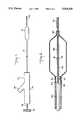
- FIG. 4is plan view of the proximal end of the catheter of an embodiment of the invention showing an adaptor and rotatable knob in cross section.
- FIG. 5is an enlarged cross sectional view of the forward compression seal region of the adaptor of FIG. 4.
- the guide tubeneed not be attached to catheter tube 12. Instead, it can float freely in the lumen of tube 12. When not so attached, there is even less need for stress relief cut 29 (FIG. 8), although it still may be provided.
- a shoulder 38is formed where they meet.
- the outside diameter of the shoulderis made larger than the inside diameter of guide tube 28.
- Y body leg 70terminates in an enlarged segment 96 having an internal thread 106.
- a second compression seal 98is placed within segment 96 between back-up plates 100 and 102. Seal 98 has a hollow passage therethrough designed to accept therein guide wire 18.
- adaptor 16offers the physician a degree of flexibility heretofore unheard of. For example, it permits removal of the guide wire from the catheter without removing the fitting. This can be accomplished simply by unscrewing compression knob 108 from enlarged segment 96 of leg 70 and loosening compression cap 132 so as to release the grip of collet 134. After the guide wire has been removed, compression knob 108 can be replaced by a solid cap (not shown). Screwing such a cap into enlarged segment 96 would maintain a fluid tight seal at the proximal end of the adaptor.
- a suitable arteryusually the femoral artery
- the balloon catheteris then inserted into the artery and fed through the arterial tree, again, all in conventional fashion. Initially, and until an obstruction is reached, the balloon can be advanced simply by pushing on the catheter tube.
- rotating knob 22can be used to steer the distal tip of guide wire 18 around it. Also, axial force can be applied to knob 22 to facilitate feeding of the balloon past the obstruction. Feeding of the balloon through the arterial system can continue by pushing on tube 12 and/or on fitting 16 simultaneously, thereby causing the transmission of axial forces to be shared by the catheter tube and the safety guide.
Landscapes
- Health & Medical Sciences (AREA)
- Heart & Thoracic Surgery (AREA)
- Life Sciences & Earth Sciences (AREA)
- Anesthesiology (AREA)
- Child & Adolescent Psychology (AREA)
- Biophysics (AREA)
- Pulmonology (AREA)
- Engineering & Computer Science (AREA)
- Vascular Medicine (AREA)
- Biomedical Technology (AREA)
- Hematology (AREA)
- Animal Behavior & Ethology (AREA)
- General Health & Medical Sciences (AREA)
- Public Health (AREA)
- Veterinary Medicine (AREA)
- Media Introduction/Drainage Providing Device (AREA)
Abstract
Description
Claims (46)
Priority Applications (13)
| Application Number | Priority Date | Filing Date | Title |
|---|---|---|---|
| US07/743,189US5318529A (en) | 1989-09-06 | 1991-08-09 | Angioplasty balloon catheter and adaptor |
| AU20631/92AAU661002B2 (en) | 1991-08-09 | 1992-07-29 | Angioplasty balloon catheter and adaptor |
| CA002075386ACA2075386A1 (en) | 1991-08-09 | 1992-08-06 | Fixed-wire balloon angioplasty catheter |
| JP4210235AJPH05237192A (en) | 1991-08-09 | 1992-08-06 | Angioplasty balloon catheter and adapter |
| AT92113497TATE171631T1 (en) | 1991-08-09 | 1992-08-07 | BALLOON CATHETER FOR ANGIOPLASTY AND ADAPTER |
| BR929203081ABR9203081A (en) | 1991-08-09 | 1992-08-07 | BALLOON CATHETER SET, AND ADAPTER TO CONNECT A CATHETER TO AN EXTERNAL DEVICE |
| AR92322925AAR245597A1 (en) | 1991-08-09 | 1992-08-07 | Angioplasty balloon catheter and adaptor |
| EP92113497AEP0528294B1 (en) | 1991-08-09 | 1992-08-07 | Angioplasty balloon catheter and adaptor |
| DE69227163TDE69227163T2 (en) | 1991-08-09 | 1992-08-07 | Balloon catheter for angioplasty and adapter |
| MX9204603AMX9204603A (en) | 1991-08-09 | 1992-08-07 | BALLOON CATHETER FOR ANGIOPLASTY AND ADAPTER. |
| US08/229,696US5501668A (en) | 1991-08-09 | 1994-04-19 | Angioplasty balloon catheter and adaptor |
| US08/616,618US5800391A (en) | 1989-09-06 | 1996-03-15 | Angioplasty balloon catheter and adaptor |
| US09/144,707US6033381A (en) | 1989-09-06 | 1998-09-01 | Angioplasty balloon catheter and adaptor |
Applications Claiming Priority (3)
| Application Number | Priority Date | Filing Date | Title |
|---|---|---|---|
| US40349789A | 1989-09-06 | 1989-09-06 | |
| US65738191A | 1991-02-19 | 1991-02-19 | |
| US07/743,189US5318529A (en) | 1989-09-06 | 1991-08-09 | Angioplasty balloon catheter and adaptor |
Related Parent Applications (2)
| Application Number | Title | Priority Date | Filing Date |
|---|---|---|---|
| US65738191AContinuation-In-Part | 1989-09-06 | 1991-02-19 | |
| US65738191AContinuation | 1989-09-06 | 1991-02-19 |
Related Child Applications (1)
| Application Number | Title | Priority Date | Filing Date |
|---|---|---|---|
| US08/229,696ContinuationUS5501668A (en) | 1989-09-06 | 1994-04-19 | Angioplasty balloon catheter and adaptor |
Publications (1)
| Publication Number | Publication Date |
|---|---|
| US5318529Atrue US5318529A (en) | 1994-06-07 |
Family
ID=24987839
Family Applications (4)
| Application Number | Title | Priority Date | Filing Date |
|---|---|---|---|
| US07/743,189Expired - LifetimeUS5318529A (en) | 1989-09-06 | 1991-08-09 | Angioplasty balloon catheter and adaptor |
| US08/229,696Expired - Fee RelatedUS5501668A (en) | 1989-09-06 | 1994-04-19 | Angioplasty balloon catheter and adaptor |
| US08/616,618Expired - LifetimeUS5800391A (en) | 1989-09-06 | 1996-03-15 | Angioplasty balloon catheter and adaptor |
| US09/144,707Expired - Fee RelatedUS6033381A (en) | 1989-09-06 | 1998-09-01 | Angioplasty balloon catheter and adaptor |
Family Applications After (3)
| Application Number | Title | Priority Date | Filing Date |
|---|---|---|---|
| US08/229,696Expired - Fee RelatedUS5501668A (en) | 1989-09-06 | 1994-04-19 | Angioplasty balloon catheter and adaptor |
| US08/616,618Expired - LifetimeUS5800391A (en) | 1989-09-06 | 1996-03-15 | Angioplasty balloon catheter and adaptor |
| US09/144,707Expired - Fee RelatedUS6033381A (en) | 1989-09-06 | 1998-09-01 | Angioplasty balloon catheter and adaptor |
Country Status (10)
| Country | Link |
|---|---|
| US (4) | US5318529A (en) |
| EP (1) | EP0528294B1 (en) |
| JP (1) | JPH05237192A (en) |
| AR (1) | AR245597A1 (en) |
| AT (1) | ATE171631T1 (en) |
| AU (1) | AU661002B2 (en) |
| BR (1) | BR9203081A (en) |
| CA (1) | CA2075386A1 (en) |
| DE (1) | DE69227163T2 (en) |
| MX (1) | MX9204603A (en) |
Cited By (94)
| Publication number | Priority date | Publication date | Assignee | Title |
|---|---|---|---|---|
| US5417658A (en)* | 1992-03-17 | 1995-05-23 | Scimed Life Systems, Inc. | Balloon dilatation catheter having a torsionally soft component |
| US5441484A (en)* | 1992-03-17 | 1995-08-15 | Scimed Life Systems, Inc. | Balloon dilatation catheter having a free core wire |
| US5484409A (en)* | 1989-08-25 | 1996-01-16 | Scimed Life Systems, Inc. | Intravascular catheter and method for use thereof |
| WO1996004034A1 (en)* | 1994-08-05 | 1996-02-15 | Medtronic, Inc. | Catheter balloon distal bond |
| US5549580A (en)* | 1995-01-23 | 1996-08-27 | Cordis Corporation | Catheter having a flexible distal tip and method of manufacturing |
| WO1996030074A1 (en) | 1995-03-31 | 1996-10-03 | Micro Interventional Systems, Inc. | Single-lumen balloon catheter and method for its intraluminal introduction |
| US5567203A (en)* | 1988-02-29 | 1996-10-22 | Scimed Life Systems, Inc. | Balloon dilatation catheter with proximal hypotube |
| US5738667A (en)* | 1992-03-30 | 1998-04-14 | Cordis Corporation | Rapid exchange catheter system |
| US5810869A (en)* | 1996-11-18 | 1998-09-22 | Localmed, Inc. | Methods for loading coaxial catheters |
| US5976107A (en) | 1991-07-05 | 1999-11-02 | Scimed Life Systems. Inc. | Catheter having extendable guide wire lumen |
| US6066113A (en)* | 1995-11-02 | 2000-05-23 | Overtoom; Timotheus Theodorus Cornelis | System for treating the ureter and/or pyelo-ureter junction |
| US6113579A (en) | 1998-03-04 | 2000-09-05 | Scimed Life Systems, Inc. | Catheter tip designs and methods for improved stent crossing |
| US6517515B1 (en) | 1998-03-04 | 2003-02-11 | Scimed Life Systems, Inc. | Catheter having variable size guide wire lumen |
| US6533751B2 (en) | 2001-01-09 | 2003-03-18 | Andrew Cragg | Micro catheter and guidewire system having improved pushability and control |
| US6648854B1 (en) | 1999-05-14 | 2003-11-18 | Scimed Life Systems, Inc. | Single lumen balloon-tipped micro catheter with reinforced shaft |
| US20060136053A1 (en)* | 2003-05-27 | 2006-06-22 | Rourke Jonathan M | Method and apparatus for improving mitral valve function |
| US20070156235A1 (en)* | 2002-02-05 | 2007-07-05 | Jonathan Rourke | Method and apparatus for improving mitral valve function |
| US20080103590A1 (en)* | 2002-01-14 | 2008-05-01 | Taylor Daniel C | Method and apparatus for reducing mitral regurgitation |
| US20090181345A1 (en)* | 2006-05-08 | 2009-07-16 | Efraim Kfir | Assembly for lifting the sinus membrane for use in dental implant surgery |
| WO2010051029A1 (en)* | 2008-10-29 | 2010-05-06 | Viacor, Inc. | Method and apparatus for improving mitral valve function |
| US20100262225A1 (en)* | 2007-12-12 | 2010-10-14 | Peter Schneider | Device and method for tacking plaque to a blood vessel wall |
| US7824345B2 (en) | 2003-12-22 | 2010-11-02 | Boston Scientific Scimed, Inc. | Medical device with push force limiter |
| US7841994B2 (en) | 2007-11-02 | 2010-11-30 | Boston Scientific Scimed, Inc. | Medical device for crossing an occlusion in a vessel |
| US7850623B2 (en) | 2005-10-27 | 2010-12-14 | Boston Scientific Scimed, Inc. | Elongate medical device with continuous reinforcement member |
| US7914467B2 (en) | 2002-07-25 | 2011-03-29 | Boston Scientific Scimed, Inc. | Tubular member having tapered transition for use in a medical device |
| US20110208287A1 (en)* | 2009-03-25 | 2011-08-25 | Svelte Medical Systems, Inc. | Stent Delivery Catheter With Balloon Control Bands |
| US8105246B2 (en) | 2007-08-03 | 2012-01-31 | Boston Scientific Scimed, Inc. | Elongate medical device having enhanced torque and methods thereof |
| US8137293B2 (en) | 2009-11-17 | 2012-03-20 | Boston Scientific Scimed, Inc. | Guidewires including a porous nickel-titanium alloy |
| US8292150B2 (en) | 2010-11-02 | 2012-10-23 | Tyco Healthcare Group Lp | Adapter for powered surgical devices |
| US8377035B2 (en) | 2003-01-17 | 2013-02-19 | Boston Scientific Scimed, Inc. | Unbalanced reinforcement members for medical device |
| US8376961B2 (en) | 2008-04-07 | 2013-02-19 | Boston Scientific Scimed, Inc. | Micromachined composite guidewire structure with anisotropic bending properties |
| US8409114B2 (en) | 2007-08-02 | 2013-04-02 | Boston Scientific Scimed, Inc. | Composite elongate medical device including distal tubular member |
| US8449526B2 (en) | 2001-07-05 | 2013-05-28 | Boston Scientific Scimed, Inc. | Torqueable soft tip medical device and method of usage |
| US8469989B2 (en) | 2010-12-15 | 2013-06-25 | Cook Medical Technologies Llc | Pushable coaxial balloon catheter |
| US8535243B2 (en) | 2008-09-10 | 2013-09-17 | Boston Scientific Scimed, Inc. | Medical devices and tapered tubular members for use in medical devices |
| US8551021B2 (en) | 2010-03-31 | 2013-10-08 | Boston Scientific Scimed, Inc. | Guidewire with an improved flexural rigidity profile |
| US8551020B2 (en) | 2006-09-13 | 2013-10-08 | Boston Scientific Scimed, Inc. | Crossing guidewire |
| US20130304185A1 (en)* | 2012-02-23 | 2013-11-14 | Covidien Lp | Methods and apparatus for luminal stenting |
| US20140046346A1 (en)* | 2012-08-09 | 2014-02-13 | Silk Road Medical, Inc. | Suture Delivery Device |
| US8795254B2 (en) | 2008-12-10 | 2014-08-05 | Boston Scientific Scimed, Inc. | Medical devices with a slotted tubular member having improved stress distribution |
| US8795202B2 (en) | 2011-02-04 | 2014-08-05 | Boston Scientific Scimed, Inc. | Guidewires and methods for making and using the same |
| US8821477B2 (en) | 2007-08-06 | 2014-09-02 | Boston Scientific Scimed, Inc. | Alternative micromachined structures |
| US20150066130A1 (en)* | 2013-08-27 | 2015-03-05 | Covidien Lp | Delivery of medical devices |
| US20150073467A1 (en)* | 2013-09-10 | 2015-03-12 | Cook Medical Technologies Llc | Tipless Balloon Catheter With Stiffening Member Through Balloon |
| US9072874B2 (en) | 2011-05-13 | 2015-07-07 | Boston Scientific Scimed, Inc. | Medical devices with a heat transfer region and a heat sink region and methods for manufacturing medical devices |
| US9233015B2 (en) | 2012-06-15 | 2016-01-12 | Trivascular, Inc. | Endovascular delivery system with an improved radiopaque marker scheme |
| AU2015202690B2 (en)* | 2012-02-23 | 2016-09-22 | Covidien Lp | Methods and apparatus for luminal stenting |
| US9539416B2 (en) | 2009-02-10 | 2017-01-10 | Vesatek, Llc | System and method for traversing an arterial occlusion |
| US9545322B2 (en) | 2007-12-12 | 2017-01-17 | Intact Vascular, Inc. | Device and method for tacking plaque to blood vessel wall |
| US9603730B2 (en) | 2007-12-12 | 2017-03-28 | Intact Vascular, Inc. | Endoluminal device and method |
| US9724222B2 (en) | 2012-07-20 | 2017-08-08 | Covidien Lp | Resheathable stent delivery system |
| US9724221B2 (en) | 2012-02-23 | 2017-08-08 | Covidien Lp | Luminal stenting |
| US9730818B2 (en) | 2007-12-12 | 2017-08-15 | Intact Vascular, Inc. | Endoluminal device and method |
| US9782186B2 (en) | 2013-08-27 | 2017-10-10 | Covidien Lp | Vascular intervention system |
| US9808595B2 (en) | 2007-08-07 | 2017-11-07 | Boston Scientific Scimed, Inc | Microfabricated catheter with improved bonding structure |
| US9849014B2 (en) | 2002-03-12 | 2017-12-26 | Covidien Lp | Medical device delivery |
| US9949853B2 (en) | 2012-04-23 | 2018-04-24 | Covidien Lp | Delivery system with hooks for resheathability |
| US10022250B2 (en) | 2007-12-12 | 2018-07-17 | Intact Vascular, Inc. | Deployment device for placement of multiple intraluminal surgical staples |
| WO2018060776A3 (en)* | 2016-09-29 | 2018-09-27 | Rapid Medical Ltd. | Rotationally torquable endovascular device with actuatable working end |
| US10086173B2 (en) | 2013-07-25 | 2018-10-02 | Merit Medical Systems, Inc. | Balloon catheter systems and methods |
| AU2016277624B2 (en)* | 2012-02-23 | 2018-11-15 | Covidien Lp | A stent delivery system |
| US10130500B2 (en) | 2013-07-25 | 2018-11-20 | Covidien Lp | Methods and apparatus for luminal stenting |
| US10166127B2 (en) | 2007-12-12 | 2019-01-01 | Intact Vascular, Inc. | Endoluminal device and method |
| US10226263B2 (en) | 2015-12-23 | 2019-03-12 | Incuvate, Llc | Aspiration monitoring system and method |
| US10245167B2 (en) | 2015-01-29 | 2019-04-02 | Intact Vascular, Inc. | Delivery device and method of delivery |
| US10271973B2 (en) | 2011-06-03 | 2019-04-30 | Intact Vascular, Inc. | Endovascular implant |
| US10278839B2 (en) | 2007-12-12 | 2019-05-07 | Intact Vascular, Inc. | Endovascular impant |
| US10357242B2 (en) | 2008-08-13 | 2019-07-23 | Silk Road Medical, Inc. | Suture delivery device |
| US10376396B2 (en) | 2017-01-19 | 2019-08-13 | Covidien Lp | Coupling units for medical device delivery systems |
| US10433852B2 (en) | 2017-05-08 | 2019-10-08 | William Z. H'Doubler | Aortic occlusion balloon apparatus, system and method of making |
| US10561440B2 (en) | 2015-09-03 | 2020-02-18 | Vesatek, Llc | Systems and methods for manipulating medical devices |
| US10786377B2 (en) | 2018-04-12 | 2020-09-29 | Covidien Lp | Medical device delivery |
| US10898356B2 (en) | 2015-01-29 | 2021-01-26 | Intact Vascular, Inc. | Delivery device and method of delivery |
| US10952882B2 (en) | 2007-07-18 | 2021-03-23 | Silk Road Medical, Inc. | Systems and methods for treating a carotid artery |
| US10993824B2 (en) | 2016-01-01 | 2021-05-04 | Intact Vascular, Inc. | Delivery device and method of delivery |
| US11071637B2 (en) | 2018-04-12 | 2021-07-27 | Covidien Lp | Medical device delivery |
| US11116939B2 (en) | 2018-03-06 | 2021-09-14 | Medtronic Vascular, Inc. | Rapid exchange balloon catheter |
| US11123209B2 (en) | 2018-04-12 | 2021-09-21 | Covidien Lp | Medical device delivery |
| US11154692B2 (en) | 2019-10-30 | 2021-10-26 | Rapid Medical Ltd. | Intraluminal device with looped core wire |
| US11285300B2 (en) | 2015-08-12 | 2022-03-29 | Vesatek, Llc | System and method for manipulating an elongate medical device |
| US11389172B2 (en) | 2016-09-29 | 2022-07-19 | Rapid Medical Ltd. | Rotationally torquable endovascular device with variable flexibility tip |
| US11413176B2 (en) | 2018-04-12 | 2022-08-16 | Covidien Lp | Medical device delivery |
| US11413174B2 (en) | 2019-06-26 | 2022-08-16 | Covidien Lp | Core assembly for medical device delivery systems |
| US11534582B2 (en) | 2006-10-21 | 2022-12-27 | Vesatek, Llc | Guidewire manipulation device |
| US11653945B2 (en) | 2007-02-05 | 2023-05-23 | Walk Vascular, Llc | Thrombectomy apparatus and method |
| US11660218B2 (en) | 2017-07-26 | 2023-05-30 | Intact Vascular, Inc. | Delivery device and method of delivery |
| US11678905B2 (en) | 2018-07-19 | 2023-06-20 | Walk Vascular, Llc | Systems and methods for removal of blood and thrombotic material |
| US11944558B2 (en) | 2021-08-05 | 2024-04-02 | Covidien Lp | Medical device delivery devices, systems, and methods |
| US12042413B2 (en) | 2021-04-07 | 2024-07-23 | Covidien Lp | Delivery of medical devices |
| US12109137B2 (en) | 2021-07-30 | 2024-10-08 | Covidien Lp | Medical device delivery |
| US12150659B2 (en) | 2014-05-19 | 2024-11-26 | Walk Vascular, Llc | Systems and methods for removal of blood and thrombotic material |
| US12171445B2 (en) | 2021-02-15 | 2024-12-24 | Walk Vascular, Llc | Systems and methods for removal of blood and thrombotic material |
| US12274458B2 (en) | 2021-02-15 | 2025-04-15 | Walk Vascular, Llc | Systems and methods for removal of blood and thrombotic material |
| US12329406B2 (en) | 2008-10-13 | 2025-06-17 | Walk Vascular, Llc | Assisted aspiration catheter system |
Families Citing this family (79)
| Publication number | Priority date | Publication date | Assignee | Title |
|---|---|---|---|---|
| US5032113A (en)* | 1989-04-13 | 1991-07-16 | Scimed Life Systems, Inc. | Innerless catheter |
| US5312340A (en)* | 1992-03-17 | 1994-05-17 | Scimed Life Systems, Inc. | Balloon dilatation catheter having dual sealing plugs |
| JP3638304B2 (en)* | 1994-02-25 | 2005-04-13 | シメッド ライフ システムズ インコーポレイテッド | Intravascular catheter |
| US5429597A (en)* | 1994-03-01 | 1995-07-04 | Boston Scientific Corporation | Kink resistant balloon catheter and method for use |
| US6013085A (en)* | 1997-11-07 | 2000-01-11 | Howard; John | Method for treating stenosis of the carotid artery |
| US6156053A (en)* | 1998-05-01 | 2000-12-05 | Intella Interventional Systems, Inc. | Dual catheter assembly |
| EP1109591A4 (en)* | 1998-06-12 | 2004-08-18 | Cardiac Pacemakers Inc | Modified guidewire for left ventricular access lead |
| EP1194074A4 (en)* | 1999-05-19 | 2002-09-11 | Innerdyne Medical Inc | SYSTEM AND METHOD TO ENABLE VASCULAR ACCESS |
| US6471968B1 (en) | 2000-05-12 | 2002-10-29 | Regents Of The University Of Michigan | Multifunctional nanodevice platform |
| US6569180B1 (en)* | 2000-06-02 | 2003-05-27 | Avantec Vascular Corporation | Catheter having exchangeable balloon |
| US6620149B1 (en) | 2000-10-05 | 2003-09-16 | Scimed Life Systems, Inc. | Corewire securement system |
| US6636758B2 (en) | 2001-05-01 | 2003-10-21 | Concentric Medical, Inc. | Marker wire and process for using it |
| US6638245B2 (en)* | 2001-06-26 | 2003-10-28 | Concentric Medical, Inc. | Balloon catheter |
| US6702782B2 (en) | 2001-06-26 | 2004-03-09 | Concentric Medical, Inc. | Large lumen balloon catheter |
| US7326245B2 (en)* | 2002-01-31 | 2008-02-05 | Boston Scientific Scimed, Inc. | Medical device for delivering biologically active material |
| US7445629B2 (en)* | 2002-01-31 | 2008-11-04 | Boston Scientific Scimed, Inc. | Medical device for delivering biologically active material |
| ES2325398T3 (en) | 2003-02-26 | 2009-09-03 | Boston Scientific Limited | BALL CATETER. |
| US6994718B2 (en)* | 2003-10-29 | 2006-02-07 | Medtronic Vascular, Inc. | Distal protection device for filtering and occlusion |
| US7716801B2 (en)* | 2003-11-24 | 2010-05-18 | Medtronic Vascular, Inc. | Low-profile distal protection device |
| US7887529B2 (en)* | 2004-04-19 | 2011-02-15 | Boston Scientific Scimed, Inc. | Hybrid micro guide catheter |
| US9480589B2 (en)* | 2005-05-13 | 2016-11-01 | Boston Scientific Scimed, Inc. | Endoprosthesis delivery system |
| US7780723B2 (en) | 2005-06-13 | 2010-08-24 | Edwards Lifesciences Corporation | Heart valve delivery system |
| US20070043389A1 (en)* | 2005-08-05 | 2007-02-22 | Shintech, Llc | System for treating chronic total occlusion caused by lower extremity arterial disease |
| US20060282110A1 (en)* | 2006-07-11 | 2006-12-14 | Conor Medsystems, Inc. | Advanceable, non-removable guide wire balloon catheter delivery system for a stent and method |
| US20080015675A1 (en)* | 2006-07-11 | 2008-01-17 | Conor Medsystems, Inc. | Balloon catheter system and method |
| US7896840B2 (en)* | 2007-04-05 | 2011-03-01 | Boston Scientific Scimed, Inc. | Catheter having internal mechanisms to encourage balloon re-folding |
| WO2009009474A1 (en)* | 2007-07-09 | 2009-01-15 | Wilson-Cook Medical Inc. | Balloon catheter with deflation mechanism |
| ATE535277T1 (en)* | 2007-07-09 | 2011-12-15 | Cook Medical Technologies Llc | FOLDING CONTROL MECHANISM FOR A BALLOON |
| US8066731B2 (en) | 2007-08-20 | 2011-11-29 | Olympus Medical Systems Corp. | Treatment device |
| CA2845188A1 (en)* | 2007-10-29 | 2009-05-07 | Schwager Medica Ag | Catheter |
| WO2009151687A2 (en) | 2008-03-12 | 2009-12-17 | The Regents Of The University Of Michigan | Dendrimer conjugates |
| US9061119B2 (en) | 2008-05-09 | 2015-06-23 | Edwards Lifesciences Corporation | Low profile delivery system for transcatheter heart valve |
| US8652202B2 (en) | 2008-08-22 | 2014-02-18 | Edwards Lifesciences Corporation | Prosthetic heart valve and delivery apparatus |
| WO2010039861A2 (en) | 2008-09-30 | 2010-04-08 | The Regents Of The University Of Michigan | Dendrimer conjugates |
| US9017644B2 (en) | 2008-11-07 | 2015-04-28 | The Regents Of The University Of Michigan | Methods of treating autoimmune disorders and/or inflammatory disorders |
| WO2010116493A1 (en)* | 2009-04-07 | 2010-10-14 | 株式会社ユニシス | Compound needle with lock mechanism |
| EP2488172A4 (en) | 2009-10-13 | 2014-08-13 | Univ Michigan | DENDRIMER COMPOSITIONS AND METHODS OF SYNTHESIS |
| US8912323B2 (en) | 2009-10-30 | 2014-12-16 | The Regents Of The University Of Michigan | Multifunctional small molecules |
| US9155619B2 (en) | 2011-02-25 | 2015-10-13 | Edwards Lifesciences Corporation | Prosthetic heart valve delivery apparatus |
| EP2691141A4 (en)* | 2011-03-30 | 2014-08-27 | Univ Cornell | INTRALUMINAL ACCESS APPARATUS AND METHODS OF USING THE SAME |
| US9119716B2 (en) | 2011-07-27 | 2015-09-01 | Edwards Lifesciences Corporation | Delivery systems for prosthetic heart valve |
| WO2013085718A1 (en) | 2011-12-08 | 2013-06-13 | The Regents Of The University Of Michigan | Multifunctional small molecules |
| WO2015104589A1 (en) | 2014-01-13 | 2015-07-16 | Shanghai Lawring Biomedical Co., Ltd | Dendrimer compositions, methods of synthesis, and uses thereof |
| CA2979712C (en) | 2015-03-25 | 2024-01-23 | The Regents Of The University Of Michigan | Nanoparticle compositions for delivery of biomacromolecules |
| US9907610B2 (en) | 2015-05-07 | 2018-03-06 | Biosense Webster (Israel) Ltd. | Spring-loaded balloon |
| US10179046B2 (en) | 2015-08-14 | 2019-01-15 | Edwards Lifesciences Corporation | Gripping and pushing device for medical instrument |
| US10561496B2 (en) | 2015-09-16 | 2020-02-18 | Edwards Lifesciences Corporation | Perfusion balloon designs |
| US10350067B2 (en) | 2015-10-26 | 2019-07-16 | Edwards Lifesciences Corporation | Implant delivery capsule |
| US11259920B2 (en) | 2015-11-03 | 2022-03-01 | Edwards Lifesciences Corporation | Adapter for prosthesis delivery device and methods of use |
| US10321996B2 (en) | 2015-11-11 | 2019-06-18 | Edwards Lifesciences Corporation | Prosthetic valve delivery apparatus having clutch mechanism |
| CA3017813C (en) | 2016-03-17 | 2021-12-07 | Oslo Universitetssykehus Hf | Fusion proteins targeting tumour associated macrophages for treating cancer |
| US10799677B2 (en) | 2016-03-21 | 2020-10-13 | Edwards Lifesciences Corporation | Multi-direction steerable handles for steering catheters |
| US10799676B2 (en) | 2016-03-21 | 2020-10-13 | Edwards Lifesciences Corporation | Multi-direction steerable handles for steering catheters |
| US11219746B2 (en) | 2016-03-21 | 2022-01-11 | Edwards Lifesciences Corporation | Multi-direction steerable handles for steering catheters |
| US20190358263A1 (en) | 2016-12-07 | 2019-11-28 | Oslo Universitetssykehus Hf | Compositions and Methods for Cell Therapy |
| EP4613214A2 (en) | 2017-04-18 | 2025-09-10 | Edwards Lifesciences Corporation | Heart valve sealing devices and delivery devices therefor |
| US11224511B2 (en) | 2017-04-18 | 2022-01-18 | Edwards Lifesciences Corporation | Heart valve sealing devices and delivery devices therefor |
| US10973634B2 (en) | 2017-04-26 | 2021-04-13 | Edwards Lifesciences Corporation | Delivery apparatus for a prosthetic heart valve |
| US10959846B2 (en) | 2017-05-10 | 2021-03-30 | Edwards Lifesciences Corporation | Mitral valve spacer device |
| US10569058B2 (en)* | 2017-05-12 | 2020-02-25 | Ep Dynamics, Inc. | Introducer sheaths |
| EP4397285A3 (en) | 2017-06-30 | 2024-09-25 | Edwards Lifesciences Corporation | Lock and release mechanisms for trans-catheter implantable devices |
| CN116196149A (en) | 2017-06-30 | 2023-06-02 | 爱德华兹生命科学公司 | Transcatheter valve docking station |
| US10857334B2 (en) | 2017-07-12 | 2020-12-08 | Edwards Lifesciences Corporation | Reduced operation force inflator |
| US10806573B2 (en) | 2017-08-22 | 2020-10-20 | Edwards Lifesciences Corporation | Gear drive mechanism for heart valve delivery apparatus |
| US11051939B2 (en) | 2017-08-31 | 2021-07-06 | Edwards Lifesciences Corporation | Active introducer sheath system |
| IL316784A (en) | 2017-10-18 | 2025-01-01 | Edwards Lifesciences Corp | Catheter assembly |
| US11207499B2 (en) | 2017-10-20 | 2021-12-28 | Edwards Lifesciences Corporation | Steerable catheter |
| WO2019195641A2 (en) | 2018-04-06 | 2019-10-10 | The Regents Of The University Of Michigan | Inhibitors of rho/mrtf/srf-mediated gene transcription and methods for use of the same |
| PT3787561T (en) | 2018-04-30 | 2022-05-27 | Edwards Lifesciences Corp | DEVICES FOR CRIMPING PROSTHETIC IMPLANTS |
| CN116269937A (en) | 2018-04-30 | 2023-06-23 | 爱德华兹生命科学公司 | Push-on sheath style |
| US11844914B2 (en) | 2018-06-05 | 2023-12-19 | Edwards Lifesciences Corporation | Removable volume indicator for syringe |
| US11779728B2 (en) | 2018-11-01 | 2023-10-10 | Edwards Lifesciences Corporation | Introducer sheath with expandable introducer |
| JP7502298B2 (en) | 2018-12-11 | 2024-06-18 | エドワーズ ライフサイエンシーズ コーポレイション | Delivery system for prosthetic heart valves - Patents.com |
| WO2020123281A1 (en) | 2018-12-12 | 2020-06-18 | Edwards Lifesciences Corporation | Combined introducer and expandable sheath |
| SG11202107448UA (en) | 2019-01-16 | 2021-08-30 | Edwards Lifesciences Corp | Apparatus and method for monitoring valve expansion |
| EP4487822A3 (en) | 2020-08-24 | 2025-04-09 | Edwards Lifesciences Corporation | Commissure marker for a prosthetic heart valve |
| PL4203851T3 (en) | 2020-08-31 | 2025-06-23 | Edwards Lifesciences Corporation | Systems and methods for crimping and device preparation |
| CN113907919B (en)* | 2021-10-12 | 2023-03-24 | 江苏臻亿医疗科技有限公司 | Implant delivery handle and delivery system |
| USD1084324S1 (en) | 2023-08-01 | 2025-07-15 | Edwards Lifesciences Corporation | Handle for implant delivery device |
Citations (15)
| Publication number | Priority date | Publication date | Assignee | Title |
|---|---|---|---|---|
| US4606347A (en)* | 1983-03-25 | 1986-08-19 | Thomas J. Fogarty | Inverted balloon catheter having sealed through lumen |
| US4616653A (en)* | 1985-07-30 | 1986-10-14 | Advanced Cardiovascular Systems, Inc. | Balloon dilatation catheter with advanceable non-removable guide wire |
| EP0213752A1 (en)* | 1985-07-30 | 1987-03-11 | Advanced Cardiovascular Systems, Inc. | Steerable balloon dilatation catheter assembly having dye injection and pressure measurement capabilities |
| US4684363A (en)* | 1984-10-31 | 1987-08-04 | American Hospital Supply Corporation | Rapidly inflatable balloon catheter and method |
| US4734093A (en)* | 1985-11-21 | 1988-03-29 | Sarcem S.A. | Remote controlled catheter having a micro-balloon |
| US4775371A (en)* | 1986-09-02 | 1988-10-04 | Advanced Cardiovascular Systems, Inc. | Stiffened dilatation catheter and method of manufacture |
| US4793350A (en)* | 1987-01-06 | 1988-12-27 | Advanced Cardiovascular Systems, Inc. | Liquid filled low profile dilatation catheter |
| US4877031A (en)* | 1988-07-22 | 1989-10-31 | Advanced Cardiovascular Systems, Inc. | Steerable perfusion dilatation catheter |
| EP0368523A2 (en)* | 1988-11-10 | 1990-05-16 | C.R. Bard, Inc. | Balloon dilatation catheter with integral guidewire |
| US4998917A (en)* | 1988-05-26 | 1991-03-12 | Advanced Cardiovascular Systems, Inc. | High torque steerable dilatation catheter |
| US5002559A (en)* | 1989-11-30 | 1991-03-26 | Numed | PTCA catheter |
| US5032113A (en)* | 1989-04-13 | 1991-07-16 | Scimed Life Systems, Inc. | Innerless catheter |
| US5035686A (en)* | 1989-01-27 | 1991-07-30 | C. R. Bard, Inc. | Catheter exchange system with detachable luer fitting |
| WO1991013649A1 (en)* | 1990-03-16 | 1991-09-19 | Medtronic, Inc. | Dilatation catheter |
| WO1992008511A1 (en)* | 1990-11-19 | 1992-05-29 | Danforth Biomedical Incorporated | Highly steerable dilatation balloon catheter system |
Family Cites Families (16)
| Publication number | Priority date | Publication date | Assignee | Title |
|---|---|---|---|---|
| US4755371A (en)* | 1983-08-08 | 1988-07-05 | Columbian Chemicals Company | Method for producing carbon black |
| US4976720A (en)* | 1987-01-06 | 1990-12-11 | Advanced Cardiovascular Systems, Inc. | Vascular catheters |
| US4964409A (en)* | 1989-05-11 | 1990-10-23 | Advanced Cardiovascular Systems, Inc. | Flexible hollow guiding member with means for fluid communication therethrough |
| US4906241A (en)* | 1987-11-30 | 1990-03-06 | Boston Scientific Corporation | Dilation balloon |
| JP2812391B2 (en)* | 1988-09-29 | 1998-10-22 | キヤノン株式会社 | Pattern processing method |
| US5085636A (en)* | 1989-01-13 | 1992-02-04 | Scimed Life Systems, Inc. | Balloon catheter with inflation-deflation valve |
| JPH05502813A (en)* | 1989-12-28 | 1993-05-20 | サイムド・ライフ・システムズ・インコーポレーテッド | Expansion balloon catheter and its manufacturing method |
| CA2050278A1 (en)* | 1990-03-16 | 1991-09-17 | Leo Roucher | Dilatation catheter |
| US5176637A (en)* | 1990-04-19 | 1993-01-05 | Terumo Kabushiki Kaisha | Catheter equipped with a dilation element |
| IE67177B1 (en)* | 1990-06-18 | 1996-03-06 | Bard Inc C R | Fixed wire dilatation catheter with distal twistable segment |
| US5195989A (en)* | 1990-09-17 | 1993-03-23 | Scimed Life Systems, Inc. | Low profile catheter for increasing lumen size of a blood vessel and guide wire therefor |
| US5171221A (en)* | 1991-02-05 | 1992-12-15 | Target Therapeutics | Single lumen low profile valved balloon catheter |
| CA2068483A1 (en)* | 1991-05-15 | 1992-11-16 | Motasim Mahmoud Sirhan | Low profile dilatation catheter |
| US5217434A (en)* | 1991-10-15 | 1993-06-08 | Scimed Life Systems, Inc. | Innerless dilatation catheter with balloon stretch valve |
| US5324259A (en)* | 1991-12-18 | 1994-06-28 | Advanced Cardiovascular Systems, Inc. | Intravascular catheter with means to seal guidewire port |
| WO1993018816A1 (en)* | 1992-03-17 | 1993-09-30 | Scimed Life Systems, Inc. | Balloon dilatation catheter having a free core wire |
- 1991
- 1991-08-09USUS07/743,189patent/US5318529A/ennot_activeExpired - Lifetime
- 1992
- 1992-07-29AUAU20631/92Apatent/AU661002B2/ennot_activeCeased
- 1992-08-06JPJP4210235Apatent/JPH05237192A/ennot_activeWithdrawn
- 1992-08-06CACA002075386Apatent/CA2075386A1/ennot_activeAbandoned
- 1992-08-07MXMX9204603Apatent/MX9204603A/enunknown
- 1992-08-07ARAR92322925Apatent/AR245597A1/enactive
- 1992-08-07EPEP92113497Apatent/EP0528294B1/ennot_activeExpired - Lifetime
- 1992-08-07DEDE69227163Tpatent/DE69227163T2/ennot_activeExpired - Lifetime
- 1992-08-07BRBR929203081Apatent/BR9203081A/ennot_activeApplication Discontinuation
- 1992-08-07ATAT92113497Tpatent/ATE171631T1/ennot_activeIP Right Cessation
- 1994
- 1994-04-19USUS08/229,696patent/US5501668A/ennot_activeExpired - Fee Related
- 1996
- 1996-03-15USUS08/616,618patent/US5800391A/ennot_activeExpired - Lifetime
- 1998
- 1998-09-01USUS09/144,707patent/US6033381A/ennot_activeExpired - Fee Related
Patent Citations (16)
| Publication number | Priority date | Publication date | Assignee | Title |
|---|---|---|---|---|
| US4606347A (en)* | 1983-03-25 | 1986-08-19 | Thomas J. Fogarty | Inverted balloon catheter having sealed through lumen |
| US4684363A (en)* | 1984-10-31 | 1987-08-04 | American Hospital Supply Corporation | Rapidly inflatable balloon catheter and method |
| US4616653A (en)* | 1985-07-30 | 1986-10-14 | Advanced Cardiovascular Systems, Inc. | Balloon dilatation catheter with advanceable non-removable guide wire |
| EP0213752A1 (en)* | 1985-07-30 | 1987-03-11 | Advanced Cardiovascular Systems, Inc. | Steerable balloon dilatation catheter assembly having dye injection and pressure measurement capabilities |
| US4734093A (en)* | 1985-11-21 | 1988-03-29 | Sarcem S.A. | Remote controlled catheter having a micro-balloon |
| US4775371A (en)* | 1986-09-02 | 1988-10-04 | Advanced Cardiovascular Systems, Inc. | Stiffened dilatation catheter and method of manufacture |
| US4793350A (en)* | 1987-01-06 | 1988-12-27 | Advanced Cardiovascular Systems, Inc. | Liquid filled low profile dilatation catheter |
| US4998917A (en)* | 1988-05-26 | 1991-03-12 | Advanced Cardiovascular Systems, Inc. | High torque steerable dilatation catheter |
| US4877031A (en)* | 1988-07-22 | 1989-10-31 | Advanced Cardiovascular Systems, Inc. | Steerable perfusion dilatation catheter |
| EP0368523A2 (en)* | 1988-11-10 | 1990-05-16 | C.R. Bard, Inc. | Balloon dilatation catheter with integral guidewire |
| US5135487A (en)* | 1988-11-10 | 1992-08-04 | C. R. Bard, Inc. | Balloon dilatation catheter with integral guidewire |
| US5035686A (en)* | 1989-01-27 | 1991-07-30 | C. R. Bard, Inc. | Catheter exchange system with detachable luer fitting |
| US5032113A (en)* | 1989-04-13 | 1991-07-16 | Scimed Life Systems, Inc. | Innerless catheter |
| US5002559A (en)* | 1989-11-30 | 1991-03-26 | Numed | PTCA catheter |
| WO1991013649A1 (en)* | 1990-03-16 | 1991-09-19 | Medtronic, Inc. | Dilatation catheter |
| WO1992008511A1 (en)* | 1990-11-19 | 1992-05-29 | Danforth Biomedical Incorporated | Highly steerable dilatation balloon catheter system |
Non-Patent Citations (1)
| Title |
|---|
| Eur. Pat. Off. Search Report for Eur. Pat. Appln. 92113497.9.* |
Cited By (169)
| Publication number | Priority date | Publication date | Assignee | Title |
|---|---|---|---|---|
| US5567203A (en)* | 1988-02-29 | 1996-10-22 | Scimed Life Systems, Inc. | Balloon dilatation catheter with proximal hypotube |
| US5484409A (en)* | 1989-08-25 | 1996-01-16 | Scimed Life Systems, Inc. | Intravascular catheter and method for use thereof |
| US5976107A (en) | 1991-07-05 | 1999-11-02 | Scimed Life Systems. Inc. | Catheter having extendable guide wire lumen |
| US5441484A (en)* | 1992-03-17 | 1995-08-15 | Scimed Life Systems, Inc. | Balloon dilatation catheter having a free core wire |
| US5417658A (en)* | 1992-03-17 | 1995-05-23 | Scimed Life Systems, Inc. | Balloon dilatation catheter having a torsionally soft component |
| US5738667A (en)* | 1992-03-30 | 1998-04-14 | Cordis Corporation | Rapid exchange catheter system |
| WO1996004034A1 (en)* | 1994-08-05 | 1996-02-15 | Medtronic, Inc. | Catheter balloon distal bond |
| US5549580A (en)* | 1995-01-23 | 1996-08-27 | Cordis Corporation | Catheter having a flexible distal tip and method of manufacturing |
| WO1996030074A1 (en) | 1995-03-31 | 1996-10-03 | Micro Interventional Systems, Inc. | Single-lumen balloon catheter and method for its intraluminal introduction |
| US5776099A (en)* | 1995-03-31 | 1998-07-07 | Micro Interventional Systems | Single lumen balloon catheter and method for its intraluminal introduction |
| EP0817657A4 (en)* | 1995-03-31 | 1998-11-18 | Micro Interventional Systems I | Single-lumen balloon catheter and method for its intraluminal introduction |
| US6066113A (en)* | 1995-11-02 | 2000-05-23 | Overtoom; Timotheus Theodorus Cornelis | System for treating the ureter and/or pyelo-ureter junction |
| US5810869A (en)* | 1996-11-18 | 1998-09-22 | Localmed, Inc. | Methods for loading coaxial catheters |
| US6113579A (en) | 1998-03-04 | 2000-09-05 | Scimed Life Systems, Inc. | Catheter tip designs and methods for improved stent crossing |
| US6517515B1 (en) | 1998-03-04 | 2003-02-11 | Scimed Life Systems, Inc. | Catheter having variable size guide wire lumen |
| US6648854B1 (en) | 1999-05-14 | 2003-11-18 | Scimed Life Systems, Inc. | Single lumen balloon-tipped micro catheter with reinforced shaft |
| US6533751B2 (en) | 2001-01-09 | 2003-03-18 | Andrew Cragg | Micro catheter and guidewire system having improved pushability and control |
| US8449526B2 (en) | 2001-07-05 | 2013-05-28 | Boston Scientific Scimed, Inc. | Torqueable soft tip medical device and method of usage |
| US20080103590A1 (en)* | 2002-01-14 | 2008-05-01 | Taylor Daniel C | Method and apparatus for reducing mitral regurgitation |
| US20070156235A1 (en)* | 2002-02-05 | 2007-07-05 | Jonathan Rourke | Method and apparatus for improving mitral valve function |
| US9849014B2 (en) | 2002-03-12 | 2017-12-26 | Covidien Lp | Medical device delivery |
| US7914467B2 (en) | 2002-07-25 | 2011-03-29 | Boston Scientific Scimed, Inc. | Tubular member having tapered transition for use in a medical device |
| US8377035B2 (en) | 2003-01-17 | 2013-02-19 | Boston Scientific Scimed, Inc. | Unbalanced reinforcement members for medical device |
| US20060136053A1 (en)* | 2003-05-27 | 2006-06-22 | Rourke Jonathan M | Method and apparatus for improving mitral valve function |
| US7824345B2 (en) | 2003-12-22 | 2010-11-02 | Boston Scientific Scimed, Inc. | Medical device with push force limiter |
| US8231551B2 (en) | 2005-10-27 | 2012-07-31 | Boston Scientific Scimed, Inc. | Elongate medical device with continuous reinforcement member |
| US7850623B2 (en) | 2005-10-27 | 2010-12-14 | Boston Scientific Scimed, Inc. | Elongate medical device with continuous reinforcement member |
| US20090181345A1 (en)* | 2006-05-08 | 2009-07-16 | Efraim Kfir | Assembly for lifting the sinus membrane for use in dental implant surgery |
| US8333589B2 (en) | 2006-05-08 | 2012-12-18 | Miambe Ltd. | Assembly for lifting the sinus membrane for use in dental implant surgery |
| US8551020B2 (en) | 2006-09-13 | 2013-10-08 | Boston Scientific Scimed, Inc. | Crossing guidewire |
| US11534582B2 (en) | 2006-10-21 | 2022-12-27 | Vesatek, Llc | Guidewire manipulation device |
| US11653945B2 (en) | 2007-02-05 | 2023-05-23 | Walk Vascular, Llc | Thrombectomy apparatus and method |
| US12369940B2 (en) | 2007-02-05 | 2025-07-29 | Walk Vascular, Llc | Thrombectomy apparatus and method |
| US10952882B2 (en) | 2007-07-18 | 2021-03-23 | Silk Road Medical, Inc. | Systems and methods for treating a carotid artery |
| US12156960B2 (en) | 2007-07-18 | 2024-12-03 | Silk Road Medical, Inc. | Systems and methods for treating a carotid artery |
| US8409114B2 (en) | 2007-08-02 | 2013-04-02 | Boston Scientific Scimed, Inc. | Composite elongate medical device including distal tubular member |
| US8105246B2 (en) | 2007-08-03 | 2012-01-31 | Boston Scientific Scimed, Inc. | Elongate medical device having enhanced torque and methods thereof |
| US8821477B2 (en) | 2007-08-06 | 2014-09-02 | Boston Scientific Scimed, Inc. | Alternative micromachined structures |
| US9808595B2 (en) | 2007-08-07 | 2017-11-07 | Boston Scientific Scimed, Inc | Microfabricated catheter with improved bonding structure |
| US7841994B2 (en) | 2007-11-02 | 2010-11-30 | Boston Scientific Scimed, Inc. | Medical device for crossing an occlusion in a vessel |
| US8128677B2 (en)* | 2007-12-12 | 2012-03-06 | Intact Vascular LLC | Device and method for tacking plaque to a blood vessel wall |
| US10835395B2 (en) | 2007-12-12 | 2020-11-17 | Intact Vascular, Inc. | Method of treating atherosclerotic occlusive disease |
| US10299945B2 (en) | 2007-12-12 | 2019-05-28 | Intact Vascular, Inc. | Method of treating atherosclerotic occlusive disease |
| US10117762B2 (en) | 2007-12-12 | 2018-11-06 | Intact Vascular, Inc. | Endoluminal device and method |
| US10188533B2 (en) | 2007-12-12 | 2019-01-29 | Intact Vascular, Inc. | Minimal surface area contact device for holding plaque to blood vessel wall |
| US10799374B2 (en) | 2007-12-12 | 2020-10-13 | Intact Vascular, Inc. | Device and method for tacking plaque to blood vessel wall |
| US9545322B2 (en) | 2007-12-12 | 2017-01-17 | Intact Vascular, Inc. | Device and method for tacking plaque to blood vessel wall |
| US10022250B2 (en) | 2007-12-12 | 2018-07-17 | Intact Vascular, Inc. | Deployment device for placement of multiple intraluminal surgical staples |
| US10166127B2 (en) | 2007-12-12 | 2019-01-01 | Intact Vascular, Inc. | Endoluminal device and method |
| US9974670B2 (en) | 2007-12-12 | 2018-05-22 | Intact Vascular, Inc. | Method of treating atherosclerotic occlusive disease |
| US20100262225A1 (en)* | 2007-12-12 | 2010-10-14 | Peter Schneider | Device and method for tacking plaque to a blood vessel wall |
| US10660771B2 (en) | 2007-12-12 | 2020-05-26 | Intact Vacsular, Inc. | Deployment device for placement of multiple intraluminal surgical staples |
| US9603730B2 (en) | 2007-12-12 | 2017-03-28 | Intact Vascular, Inc. | Endoluminal device and method |
| US10278839B2 (en) | 2007-12-12 | 2019-05-07 | Intact Vascular, Inc. | Endovascular impant |
| US9730818B2 (en) | 2007-12-12 | 2017-08-15 | Intact Vascular, Inc. | Endoluminal device and method |
| US8376961B2 (en) | 2008-04-07 | 2013-02-19 | Boston Scientific Scimed, Inc. | Micromachined composite guidewire structure with anisotropic bending properties |
| US11389155B2 (en) | 2008-08-13 | 2022-07-19 | Silk Road Medical, Inc. | Suture delivery device |
| US10357242B2 (en) | 2008-08-13 | 2019-07-23 | Silk Road Medical, Inc. | Suture delivery device |
| US8535243B2 (en) | 2008-09-10 | 2013-09-17 | Boston Scientific Scimed, Inc. | Medical devices and tapered tubular members for use in medical devices |
| US12329406B2 (en) | 2008-10-13 | 2025-06-17 | Walk Vascular, Llc | Assisted aspiration catheter system |
| WO2010051029A1 (en)* | 2008-10-29 | 2010-05-06 | Viacor, Inc. | Method and apparatus for improving mitral valve function |
| US8795254B2 (en) | 2008-12-10 | 2014-08-05 | Boston Scientific Scimed, Inc. | Medical devices with a slotted tubular member having improved stress distribution |
| US10682501B2 (en) | 2009-02-10 | 2020-06-16 | Vesatek, Llc | System and method for traversing an arterial occlusion |
| US9539416B2 (en) | 2009-02-10 | 2017-01-10 | Vesatek, Llc | System and method for traversing an arterial occlusion |
| US11660424B2 (en) | 2009-02-10 | 2023-05-30 | Vesatek, Llc | System and method for traversing an arterial occlusion |
| US20110208287A1 (en)* | 2009-03-25 | 2011-08-25 | Svelte Medical Systems, Inc. | Stent Delivery Catheter With Balloon Control Bands |
| US8968348B2 (en)* | 2009-03-25 | 2015-03-03 | Svelte Medical Systems, Inc. | Balloon delivery apparatus and method for using and manufacturing the same |
| USRE47514E1 (en)* | 2009-03-25 | 2019-07-16 | Svelte Medical Systems, Inc. | Balloon delivery apparatus and method for using and manufacturing the same |
| US20120053604A1 (en)* | 2009-03-25 | 2012-03-01 | Svelte Medical Systems, Inc. | Balloon Delivery Apparatus and Method for Using and Manufacturing the Same |
| US9387103B2 (en) | 2009-03-25 | 2016-07-12 | Svelte Medical Systems, Inc. | Stent delivery catheter with balloon control bands |
| US9849013B2 (en) | 2009-03-25 | 2017-12-26 | Svelte Medical Systems, Inc. | Stent delivery catheter |
| US9061126B2 (en) | 2009-03-25 | 2015-06-23 | Svelte Medical Systems, Inc. | Stent delivery catheter with balloon control bands |
| US9585781B2 (en) | 2009-03-25 | 2017-03-07 | Svelte Medical Systems, Inc. | Stent delivery catheter with balloon control bands |
| US10888443B2 (en) | 2009-06-11 | 2021-01-12 | Intact Vascular, Inc. | Device for holding plaque to blood vessel wall |
| US10779971B2 (en) | 2009-06-11 | 2020-09-22 | Intact Vascular, Inc. | Endovascular implant |
| US8137293B2 (en) | 2009-11-17 | 2012-03-20 | Boston Scientific Scimed, Inc. | Guidewires including a porous nickel-titanium alloy |
| US8551021B2 (en) | 2010-03-31 | 2013-10-08 | Boston Scientific Scimed, Inc. | Guidewire with an improved flexural rigidity profile |
| US8784337B2 (en) | 2010-03-31 | 2014-07-22 | Boston Scientific Scimed, Inc. | Catheter with an improved flexural rigidity profile |
| US10137013B2 (en) | 2010-05-29 | 2018-11-27 | Intact Vascular, Inc. | Endoluminal device and method |
| US10779968B2 (en) | 2010-05-29 | 2020-09-22 | Intact Vascular, Inc. | Endoluminal device and method |
| US9282963B2 (en) | 2010-11-02 | 2016-03-15 | Covidien Lp | Adapter for powered surgical devices |
| US10004504B2 (en) | 2010-11-02 | 2018-06-26 | Covidien Lp | Adapter for powered surgical devices |
| US10758235B2 (en) | 2010-11-02 | 2020-09-01 | Covidien Lp | Adapter for powered surgical devices |
| US8292150B2 (en) | 2010-11-02 | 2012-10-23 | Tyco Healthcare Group Lp | Adapter for powered surgical devices |
| US8469989B2 (en) | 2010-12-15 | 2013-06-25 | Cook Medical Technologies Llc | Pushable coaxial balloon catheter |
| US8795202B2 (en) | 2011-02-04 | 2014-08-05 | Boston Scientific Scimed, Inc. | Guidewires and methods for making and using the same |
| US9072874B2 (en) | 2011-05-13 | 2015-07-07 | Boston Scientific Scimed, Inc. | Medical devices with a heat transfer region and a heat sink region and methods for manufacturing medical devices |
| US10271973B2 (en) | 2011-06-03 | 2019-04-30 | Intact Vascular, Inc. | Endovascular implant |
| US10390977B2 (en) | 2011-06-03 | 2019-08-27 | Intact Vascular, Inc. | Endovascular implant |
| US10285831B2 (en) | 2011-06-03 | 2019-05-14 | Intact Vascular, Inc. | Endovascular implant |
| US10779969B2 (en) | 2011-06-03 | 2020-09-22 | Intact Vascular, Inc. | Endovascular implant and deployment devices |
| KR20160101200A (en)* | 2012-02-23 | 2016-08-24 | 코비디엔 엘피 | Methods and apparatus for luminal stenting |
| AU2015202690B2 (en)* | 2012-02-23 | 2016-09-22 | Covidien Lp | Methods and apparatus for luminal stenting |
| AU2019201096B2 (en)* | 2012-02-23 | 2020-04-09 | Covidien Lp | A stent delivery system |
| US10537452B2 (en) | 2012-02-23 | 2020-01-21 | Covidien Lp | Luminal stenting |
| US11259946B2 (en) | 2012-02-23 | 2022-03-01 | Covidien Lp | Luminal stenting |
| US9675488B2 (en) | 2012-02-23 | 2017-06-13 | Covidien Lp | Luminal stenting |
| US20130304185A1 (en)* | 2012-02-23 | 2013-11-14 | Covidien Lp | Methods and apparatus for luminal stenting |
| AU2016277624B2 (en)* | 2012-02-23 | 2018-11-15 | Covidien Lp | A stent delivery system |
| US9724221B2 (en) | 2012-02-23 | 2017-08-08 | Covidien Lp | Luminal stenting |
| US9308110B2 (en) | 2012-02-23 | 2016-04-12 | Covidien Lp | Luminal stenting |
| US9949853B2 (en) | 2012-04-23 | 2018-04-24 | Covidien Lp | Delivery system with hooks for resheathability |
| US10034787B2 (en) | 2012-06-15 | 2018-07-31 | Trivascular, Inc. | Endovascular delivery system with an improved radiopaque marker scheme |
| US9233015B2 (en) | 2012-06-15 | 2016-01-12 | Trivascular, Inc. | Endovascular delivery system with an improved radiopaque marker scheme |
| US11013626B2 (en) | 2012-06-15 | 2021-05-25 | Trivascular, Inc. | Endovascular delivery system with an improved radiopaque marker scheme |
| US9724222B2 (en) | 2012-07-20 | 2017-08-08 | Covidien Lp | Resheathable stent delivery system |
| US11839372B2 (en) | 2012-08-09 | 2023-12-12 | Silk Road Medical, Inc. | Suture delivery device |
| US10881393B2 (en) | 2012-08-09 | 2021-01-05 | Silk Road Medical, Inc. | Suture delivery device |
| US12245763B2 (en) | 2012-08-09 | 2025-03-11 | Silk Road Medical, Inc. | Suture delivery device |
| US20140046346A1 (en)* | 2012-08-09 | 2014-02-13 | Silk Road Medical, Inc. | Suture Delivery Device |
| US10159479B2 (en)* | 2012-08-09 | 2018-12-25 | Silk Road Medical, Inc. | Suture delivery device |
| US10086173B2 (en) | 2013-07-25 | 2018-10-02 | Merit Medical Systems, Inc. | Balloon catheter systems and methods |
| US10130797B2 (en) | 2013-07-25 | 2018-11-20 | Merit Medical Systems, Inc. | Balloon catheter systems and methods |
| US11219749B2 (en) | 2013-07-25 | 2022-01-11 | Merit Medical Systems, Inc. | Balloon catheter systems and methods |
| US10130500B2 (en) | 2013-07-25 | 2018-11-20 | Covidien Lp | Methods and apparatus for luminal stenting |
| US10265207B2 (en) | 2013-08-27 | 2019-04-23 | Covidien Lp | Delivery of medical devices |
| US11103374B2 (en) | 2013-08-27 | 2021-08-31 | Covidien Lp | Delivery of medical devices |
| US9474639B2 (en)* | 2013-08-27 | 2016-10-25 | Covidien Lp | Delivery of medical devices |
| US10092431B2 (en) | 2013-08-27 | 2018-10-09 | Covidien Lp | Delivery of medical devices |
| US10045867B2 (en) | 2013-08-27 | 2018-08-14 | Covidien Lp | Delivery of medical devices |
| US9775733B2 (en) | 2013-08-27 | 2017-10-03 | Covidien Lp | Delivery of medical devices |
| US9827126B2 (en) | 2013-08-27 | 2017-11-28 | Covidien Lp | Delivery of medical devices |
| US11076972B2 (en) | 2013-08-27 | 2021-08-03 | Covidien Lp | Delivery of medical devices |
| US10695204B2 (en) | 2013-08-27 | 2020-06-30 | Covidien Lp | Delivery of medical devices |
| US12343273B2 (en) | 2013-08-27 | 2025-07-01 | Covidien Lp | Delivery of medical devices |
| US9782186B2 (en) | 2013-08-27 | 2017-10-10 | Covidien Lp | Vascular intervention system |
| US20150066130A1 (en)* | 2013-08-27 | 2015-03-05 | Covidien Lp | Delivery of medical devices |
| US20150073467A1 (en)* | 2013-09-10 | 2015-03-12 | Cook Medical Technologies Llc | Tipless Balloon Catheter With Stiffening Member Through Balloon |
| US9901716B2 (en)* | 2013-09-10 | 2018-02-27 | Cook Medical Technologies Llc | Tipless balloon catheter with stiffening member through balloon |
| US12150659B2 (en) | 2014-05-19 | 2024-11-26 | Walk Vascular, Llc | Systems and methods for removal of blood and thrombotic material |
| US12156665B2 (en) | 2014-05-19 | 2024-12-03 | Walk Vascular, Llc | Systems and methods for removal of blood and thrombotic material |
| US10898356B2 (en) | 2015-01-29 | 2021-01-26 | Intact Vascular, Inc. | Delivery device and method of delivery |
| US10245167B2 (en) | 2015-01-29 | 2019-04-02 | Intact Vascular, Inc. | Delivery device and method of delivery |
| US11304836B2 (en) | 2015-01-29 | 2022-04-19 | Intact Vascular, Inc. | Delivery device and method of delivery |
| US11285300B2 (en) | 2015-08-12 | 2022-03-29 | Vesatek, Llc | System and method for manipulating an elongate medical device |
| US11672561B2 (en) | 2015-09-03 | 2023-06-13 | Walk Vascular, Llc | Systems and methods for manipulating medical devices |
| US10561440B2 (en) | 2015-09-03 | 2020-02-18 | Vesatek, Llc | Systems and methods for manipulating medical devices |
| US11771445B2 (en) | 2015-12-23 | 2023-10-03 | Incuvate, Llc | Aspiration monitoring system and method |
| US10226263B2 (en) | 2015-12-23 | 2019-03-12 | Incuvate, Llc | Aspiration monitoring system and method |
| US11051832B2 (en) | 2015-12-23 | 2021-07-06 | Incuvate, Llc | Aspiration monitoring system and method |
| US10993824B2 (en) | 2016-01-01 | 2021-05-04 | Intact Vascular, Inc. | Delivery device and method of delivery |
| US11090464B2 (en) | 2016-09-29 | 2021-08-17 | Rapid Medical Ltd. | Rotationally torquable endovascular device with actuatable working end |
| US10918834B2 (en) | 2016-09-29 | 2021-02-16 | Rapid Medical Ltd. | Rotationally torquable endovascular device with actuatable working end |
| WO2018060776A3 (en)* | 2016-09-29 | 2018-09-27 | Rapid Medical Ltd. | Rotationally torquable endovascular device with actuatable working end |
| CN109843224A (en)* | 2016-09-29 | 2019-06-04 | 急速医疗有限公司 | Rotationally twistable intravascular device with actuatable working end |
| AU2017336603B2 (en)* | 2016-09-29 | 2022-03-31 | Rapid Medical Ltd. | Rotationally torquable endovascular device with actuatable working end |
| CN109843224B (en)* | 2016-09-29 | 2022-04-26 | 急速医疗有限公司 | Rotationally twistable intravascular device with actuatable working end |
| US11389172B2 (en) | 2016-09-29 | 2022-07-19 | Rapid Medical Ltd. | Rotationally torquable endovascular device with variable flexibility tip |
| US10376396B2 (en) | 2017-01-19 | 2019-08-13 | Covidien Lp | Coupling units for medical device delivery systems |
| US10945867B2 (en) | 2017-01-19 | 2021-03-16 | Covidien Lp | Coupling units for medical device delivery systems |
| US11833069B2 (en) | 2017-01-19 | 2023-12-05 | Covidien Lp | Coupling units for medical device delivery systems |
| US11559310B2 (en) | 2017-05-08 | 2023-01-24 | William H'Doubler | Aortic occlusion balloon apparatus, system and method of making |
| US10433852B2 (en) | 2017-05-08 | 2019-10-08 | William Z. H'Doubler | Aortic occlusion balloon apparatus, system and method of making |
| US11660218B2 (en) | 2017-07-26 | 2023-05-30 | Intact Vascular, Inc. | Delivery device and method of delivery |
| US11116939B2 (en) | 2018-03-06 | 2021-09-14 | Medtronic Vascular, Inc. | Rapid exchange balloon catheter |
| US11123209B2 (en) | 2018-04-12 | 2021-09-21 | Covidien Lp | Medical device delivery |
| US11413176B2 (en) | 2018-04-12 | 2022-08-16 | Covidien Lp | Medical device delivery |
| US11071637B2 (en) | 2018-04-12 | 2021-07-27 | Covidien Lp | Medical device delivery |
| US11648140B2 (en) | 2018-04-12 | 2023-05-16 | Covidien Lp | Medical device delivery |
| US10786377B2 (en) | 2018-04-12 | 2020-09-29 | Covidien Lp | Medical device delivery |
| US11678905B2 (en) | 2018-07-19 | 2023-06-20 | Walk Vascular, Llc | Systems and methods for removal of blood and thrombotic material |
| US11413174B2 (en) | 2019-06-26 | 2022-08-16 | Covidien Lp | Core assembly for medical device delivery systems |
| US11154692B2 (en) | 2019-10-30 | 2021-10-26 | Rapid Medical Ltd. | Intraluminal device with looped core wire |
| US12171445B2 (en) | 2021-02-15 | 2024-12-24 | Walk Vascular, Llc | Systems and methods for removal of blood and thrombotic material |
| US12171444B2 (en) | 2021-02-15 | 2024-12-24 | Walk Vascular, Llc | Systems and methods for removal of blood and thrombotic material |
| US12274458B2 (en) | 2021-02-15 | 2025-04-15 | Walk Vascular, Llc | Systems and methods for removal of blood and thrombotic material |
| US12042413B2 (en) | 2021-04-07 | 2024-07-23 | Covidien Lp | Delivery of medical devices |
| US12109137B2 (en) | 2021-07-30 | 2024-10-08 | Covidien Lp | Medical device delivery |
| US11944558B2 (en) | 2021-08-05 | 2024-04-02 | Covidien Lp | Medical device delivery devices, systems, and methods |
Also Published As
| Publication number | Publication date |
|---|---|
| AU2063192A (en) | 1993-02-11 |
| US5800391A (en) | 1998-09-01 |
| US5501668A (en) | 1996-03-26 |
| AR245597A1 (en) | 1994-02-28 |
| CA2075386A1 (en) | 1993-02-10 |
| MX9204603A (en) | 1993-02-01 |
| EP0528294B1 (en) | 1998-09-30 |
| EP0528294A2 (en) | 1993-02-24 |
| EP0528294A3 (en) | 1993-05-12 |
| US6033381A (en) | 2000-03-07 |
| DE69227163T2 (en) | 1999-05-20 |
| DE69227163D1 (en) | 1998-11-05 |
| AU661002B2 (en) | 1995-07-13 |
| BR9203081A (en) | 1993-03-30 |
| JPH05237192A (en) | 1993-09-17 |
| ATE171631T1 (en) | 1998-10-15 |
Similar Documents
| Publication | Publication Date | Title |
|---|---|---|
| US5318529A (en) | Angioplasty balloon catheter and adaptor | |
| US6183420B1 (en) | Variable stiffness angioplasty guide wire | |
| US5045061A (en) | Balloon catheter and locking guidewire system | |
| EP0629417B1 (en) | Low-profile dual-lumen perfusion balloon catheter with axially movable inner guide sheath | |
| US5383890A (en) | Low-profile single-lumen perfusion balloon catheter | |
| US4976690A (en) | Variable stiffness angioplasty catheter | |
| US6287291B1 (en) | Protective sheath for catheters | |
| US5439445A (en) | Support catheter assembly | |
| US5163903A (en) | Catheter exchange system with detachable luer fitting | |
| US5458615A (en) | Stent delivery system | |
| JP2933389B2 (en) | Balloon catheter having a guide wire lumen at the distal end | |
| US5976153A (en) | Stent delivery catheter system | |
| US5507768A (en) | Stent delivery system | |
| CA2412638C (en) | Stent delivery device | |
| EP0231601B1 (en) | Angioplasty catheter assembly | |
| US5759191A (en) | Coaxial PTCA catheter with anchor joint | |
| US20080039784A1 (en) | Multi-Lumen Catheter System | |
| US5593419A (en) | Fixed wire dilatation catheter with distal twistable segment | |
| JPH02180276A (en) | Balloon dilating catheter | |
| US7189215B2 (en) | Catheter with full-length core wire shaft for core wire interchangeability | |
| IE69028B1 (en) | Coaxial PTCA catheter with anchor joint | |
| US5341817A (en) | Elongated guidewire for use in dilation procedures | |
| US20040092868A1 (en) | Catheter with full-length core wire shaft for core wire interchangeability | |
| EP0537895B1 (en) | Angioplasty balloon catheter | |
| US20030163118A1 (en) | Catheter having a tapered distal tip and method of making |
Legal Events
| Date | Code | Title | Description |
|---|---|---|---|
| AS | Assignment | Owner name:DATASCOPE INVESTMENT CORP., NEW JERSEY Free format text:ASSIGNMENT OF ASSIGNORS INTEREST.;ASSIGNOR:KONTOS, STAVROS B.;REEL/FRAME:005809/0258 Effective date:19910801 | |
| AS | Assignment | Owner name:BOSTON SCIENTIFIC CORPORATION, MASSACHUSETTS Free format text:ASSIGNMENT OF ASSIGNORS INTEREST;ASSIGNOR:DATASCOPE CORP.;REEL/FRAME:006599/0528 Effective date:19930608 | |
| AS | Assignment | Owner name:BOSTON SCIENTIFIC CORPORATION, MASSACHUSETTS Free format text:ASSIGNMENT OF ASSIGNORS INTEREST;ASSIGNOR:DATASCOPE CORP.;REEL/FRAME:006616/0085 Effective date:19930608 | |
| STCF | Information on status: patent grant | Free format text:PATENTED CASE | |
| FPAY | Fee payment | Year of fee payment:4 | |
| FPAY | Fee payment | Year of fee payment:8 | |
| FPAY | Fee payment | Year of fee payment:12 | |
| AS | Assignment | Owner name:SCIMED LIFE SYSTEMS, INC., MINNESOTA Free format text:ASSIGNMENT OF ASSIGNORS INTEREST;ASSIGNOR:BOSTON SCIENTIFIC TECHNOLOGY, INC.;REEL/FRAME:018480/0075 Effective date:19971215 Owner name:BOSTON SCIENTIFIC SCIMED, INC., MINNESOTA Free format text:CHANGE OF NAME;ASSIGNOR:SCIMED LIFE SYSTEMS, INC.;REEL/FRAME:018480/0107 Effective date:20050101 Owner name:BOSTON SCIENTIFIC TECHNOLOGY, INC., MINNESOTA Free format text:ASSIGNMENT OF ASSIGNORS INTEREST;ASSIGNOR:BOSTON SCIENTIFIC CORPORATION;REEL/FRAME:018515/0585 Effective date:19950701 |