US5318526A - Flexible endoscope with hypotube activating wire support - Google Patents
Flexible endoscope with hypotube activating wire supportDownload PDFInfo
- Publication number
- US5318526A US5318526AUS07/954,120US95412092AUS5318526AUS 5318526 AUS5318526 AUS 5318526AUS 95412092 AUS95412092 AUS 95412092AUS 5318526 AUS5318526 AUS 5318526A
- Authority
- US
- United States
- Prior art keywords
- tube
- catheter
- distal segment
- wire
- activating wire
- Prior art date
- Legal status (The legal status is an assumption and is not a legal conclusion. Google has not performed a legal analysis and makes no representation as to the accuracy of the status listed.)
- Expired - Fee Related
Links
Images


Classifications
- A—HUMAN NECESSITIES
- A61—MEDICAL OR VETERINARY SCIENCE; HYGIENE
- A61M—DEVICES FOR INTRODUCING MEDIA INTO, OR ONTO, THE BODY; DEVICES FOR TRANSDUCING BODY MEDIA OR FOR TAKING MEDIA FROM THE BODY; DEVICES FOR PRODUCING OR ENDING SLEEP OR STUPOR
- A61M25/00—Catheters; Hollow probes
- A61M25/01—Introducing, guiding, advancing, emplacing or holding catheters
- A61M25/0105—Steering means as part of the catheter or advancing means; Markers for positioning
- A61M25/0133—Tip steering devices
- A61M25/0147—Tip steering devices with movable mechanical means, e.g. pull wires
- A—HUMAN NECESSITIES
- A61—MEDICAL OR VETERINARY SCIENCE; HYGIENE
- A61B—DIAGNOSIS; SURGERY; IDENTIFICATION
- A61B1/00—Instruments for performing medical examinations of the interior of cavities or tubes of the body by visual or photographical inspection, e.g. endoscopes; Illuminating arrangements therefor
- A61B1/005—Flexible endoscopes
- A61B1/0051—Flexible endoscopes with controlled bending of insertion part
- A61B1/0055—Constructional details of insertion parts, e.g. vertebral elements
- A—HUMAN NECESSITIES
- A61—MEDICAL OR VETERINARY SCIENCE; HYGIENE
- A61M—DEVICES FOR INTRODUCING MEDIA INTO, OR ONTO, THE BODY; DEVICES FOR TRANSDUCING BODY MEDIA OR FOR TAKING MEDIA FROM THE BODY; DEVICES FOR PRODUCING OR ENDING SLEEP OR STUPOR
- A61M25/00—Catheters; Hollow probes
- A61M25/01—Introducing, guiding, advancing, emplacing or holding catheters
- A61M25/0105—Steering means as part of the catheter or advancing means; Markers for positioning
- A61M25/0133—Tip steering devices
- A61M25/0147—Tip steering devices with movable mechanical means, e.g. pull wires
- A61M2025/015—Details of the distal fixation of the movable mechanical means
- A—HUMAN NECESSITIES
- A61—MEDICAL OR VETERINARY SCIENCE; HYGIENE
- A61M—DEVICES FOR INTRODUCING MEDIA INTO, OR ONTO, THE BODY; DEVICES FOR TRANSDUCING BODY MEDIA OR FOR TAKING MEDIA FROM THE BODY; DEVICES FOR PRODUCING OR ENDING SLEEP OR STUPOR
- A61M25/00—Catheters; Hollow probes
- A61M25/01—Introducing, guiding, advancing, emplacing or holding catheters
- A61M25/09—Guide wires
- A61M25/09016—Guide wires with mandrils
- A61M25/09033—Guide wires with mandrils with fixed mandrils, e.g. mandrils fixed to tip; Tensionable wires
Definitions
- the present inventionrelates generally to endoscopes, and more particularly to flexible endoscopes which have deflecting tips.
- Cathetersare used for a large number of surgical procedures. For example, in many relatively new surgical techniques, e.g., endoscopic surgery, a small opening is made in the patient, and one or more catheters or cannulas are inserted into the opening to provide various working passageways through which small surgical instruments can be advanced into the patient to perform the particular procedure. To keep the opening as small as possible, it is desirable to minimize the diameter of the catheters.
- the catheterbe able to bend at predetermined locations, either to aid in advancing the catheter along a tortuous path or to avoid an obstructing object inside the patient.
- Simply pre-bending a catheter at a predetermined location on the cathetercan interfere with inserting the catheter along a straight-line path, and is therefore oftentimes undesirable.
- cathetersmay be made of thin-walled strong and rigid material, such as steel. These catheters, however, cannot easily conform to the contours of a body vessel or duct. It is desirable for a catheter to conform to follow a body vessel or duct.
- Another object of the present inventionis to provide a catheter which can be bent at one or more predetermined location on the catheter. Another object of the present invention is to provide a small diameter, thin-walled bendable catheter that has a relatively high degree of structural strength. Further, it is an object of the present invention to provide a catheter which is easy to use and cost-effective to manufacture.
- a flexible catheterhas a bendable tube for conforming to the contour of a body vessel, and a selectively deflectable distal segment is connected to the tube coaxially with the tube.
- the distal segmentcan be selectively deflected without bending the flexible tube.
- an activating wirewhich has a distal end is connected to the distal segment. Also, the activating wire has a proximal end, and the proximal end is manipulable to impart tension to the activating wire to thereby cause the distal segment to deflect. Further, a holder is provided for supporting the activating wire such that substantially no tension is imparted to the tube when the activating wire is under tension. Consequently, the distal segment can be selectively deflected without bending or buckling the bendable tube.
- the deflectable distal segmenthas a distal end
- the holderincludes an axially rigid fitting which is connected to the bendable tube and to the distal segment. Additionally, an axially rigid tip is attached to the distal end of the distal segment, and a hollow column support is disposed within the tube and is attached to the fitting.
- a fitmentis fixedly attached to the tip, and the distal end of the activating wire is attached to the fitment.
- the activating wireextends through the column support in a slidable relationship therewith and does not contact the bendable tube. Consequently, when the activating wire is pulled in the proximal direction, the tension of the activating wire is transferred to the tip (and, hence, to the distal segment) to bend the distal segment, without bending the tube.
- the tubehas a working channel lumen for establishing a working channel through which an endoscopic instrument can be advanced. Also, the tube has the capacity to accept an image fiber bundle and illumination fibers.
- the column supportis a stainless steel tube such as hypodermic tubing.
- the column supportcan be a close clearance polymer tube integral to, or bonded along its entire length to, the flexible catheter tube.
- a handleis positioned in a surrounding relationship to the tube to support the tube.
- the handleincludes a deflection wheel which is rotatably engaged with the handle and which is connected to the activating wire. Accordingly, the deflection wheel can be rotated to pull the activating wire in the proximal direction and thereby bend the distal segment.
- a flexible catheterhas a flexible tube and a bendable distal segment, and the distal segment has a distal end.
- An axially rigid fittingis connected to the flexible tube and to the bendable distal segment, and an axially rigid tip is attached to the distal end of the distal segment.
- a hollow column supportis disposed within the tube and is attached to the fitting.
- an activating wireis slidably disposed within the column support and is fixedly engaged with the tip. Consequently, the activating wire is manipulable to impart a pulling force on the tip to thereby bend the distal segment without substantially bending the flexible tube.
- a method for manipulating a surgical instrument in a body vesselis provided.
- a flexible catheteris provided, and a bendable distal segment is connected to the flexible catheter.
- an activating wireis connected to the distal segment. The activating wire is supported such that when the activating wire is pulled in the proximal direction, the distal segment bends without substantially bending the flexible catheter.
- the medical instrumentis positioned in the catheter, and the catheter is advanced into the body vessel.
- the activating wirecan be manipulated to selectively bend the distal segment.
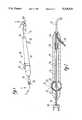
- FIG. 1is a perspective view of the flexible endoscope of the present invention, with portions broken away;
- FIG. 2is a cross-sectional view of the flexible endoscope of the present invention, as seen along the line 2--2 in FIG. 1;
- FIG. 3is a cross-sectional view of the flexible endoscope of the present invention, as seen along the line 3--3 in FIG. 1;
- FIG. 4is a cross-sectional view of the flexible endoscope of the present invention, as seen along the line 4--4 in FIG. 1, with the working channel tube and fiber optic tubes removed for clarity;
- FIG. 5is perspective view of the flexible tube of the endoscope of the present invention, with portions removed and portions broken away for clarity;
- FIG. 6is a cross-sectional view of the flexible endoscope of the present invention, as seen along the line 6--6 in FIG. 1.
- a flexible endoscopeis shown, generally designated 10.
- the endoscope 10includes a bendable tube 12 and a hollow handle 14, and the tube 12 extends distally outwardly from the handle 14.
- the handle 14is made of a strong, rigid, light-weight plastic or metal.
- FIG. 1also shows that the handle 14 has a hollow, distally-tapered frusto-conical nose piece 16.
- the nose piece 16includes a Y-fitting 18 which forms an obtuse angle with respect to the longitudinal axis of the endoscope 10.
- a light source and video display system(not shown) can be connected to the Y-fitting 18 for purposes to be subsequently disclosed.
- the handle 14also includes a deflection wheel 20.
- the deflection wheel 20is rotatable mounted on the handle 14. More specifically, the deflection wheel 20 is connected to a deflection wheel shaft 22, and the deflection wheel shaft 22 is rotatably engaged with the handle 14. Also, the deflection wheel shaft 22 is attached to or formed integrally with a deflection wheel disk 24 which is disposed within the handle 14.
- an activating wire 26is attached to the deflection wheel shaft 22.
- the activating wire 26has a diameter of about five thousandths of an inch (0.005") Additionally, the activating wire 26 is attached to a first wire anchor 28 attached to the deflection wheel 20. Accordingly, the deflection wheel 20 can be rotated, and the rotational motion of the deflection wheel 20 transferred to rotational motion of the deflection wheel disk 24 by the deflection wheel shaft 22, to thereby cause translational motion of the activating wire 26 for purposes to be disclosed below.
- the deflection wheel 20is formed with knurls 32.
- the nose piece 16is not formed integrally with the handle 14, but instead is attached to the handle 14 by adhesive bonding and preferably by depositing a urethane adhesive between the nose piece 16 and handle 14. Indeed, a portion 31 of the nose piece 16 is hollow, and is filled with an epoxy material 33. A hollow nose piece tube 34 is bonded to the nose piece 16, and the nose piece tube 34 extends into the handle 14.
- the nose piece tube 34is made of a rigid material, such as stainless steel.
- the nose piece tube 34supports a working channel tube 36, and the working channel tube 36 extends into the endoscope tube 12.
- the working channel tube 36is made of a flexible material, e.g., polyurethane such as pellethane.
- the activating wire 26is slidingly disposed in the hollow handle 14, and the wire 26 is juxtaposed with the working channel tube 36 and extends through the nose piece tube 34 into the endoscope tube 12.
- the working channel tube 36extends through the handle 14 and is coaxial with the handle 14.
- FIG. 3best shows that the deflection wheel disk 24 is positioned above the working channel tube 36 such that clearance exists between the disk 24 and working channel tube 36 to permit unimpeded manipulation of the deflection wheel 20.
- FIGS. 2 and 3further show that a handle tube 38 is bonded to the handle 14, and the working channel tube 36 extends through the handle tube 38.
- the handle tube 38is in turn bonded to a luer fitting 40.
- An appropriate connecting devicesuch as a Touhy-Borst valve (not shown) made by Cook Incorporated, can be connected to the luer fitting 40.
- a Touhy-Borst valvecan include a Y-adapter, such that the Touhy-Borst valve can provide two passageways that extend into the working channel tube 36.
- a medical instrument(not shown) can be advanced axially through the Touhy-Borst valve and the luer fitting 40 and into the working channel tube 36 while irrigant 13 is infused through the side arm of the Y adapter.
- FIGS. 4, 5, and 6show further details of the endoscope tube 12.
- the endoscope tube 12includes a cylindrical braided polyimide body 42 which is covered by an Outer plastic sheath 44.
- the sheath 44is made of polyethylene and has a thickness B of twenty five ten-thousandths of an inch (0.0025"), and the sheath 44 can be bonded to the polyimide body 42 at its ends or shrink fit around the polyimide body 42.
- the polyimide body 42is reinforced with steel braids. More specifically, referring briefly to FIGS. 5 and 6, the polyimide body 42 has a plurality of steel ribbon braids 46 imbedded therein by means well known in the art, and the braids are positioned in the body 42 in a criss-crossing weave pattern.
- the steel ribbon braids 46are positioned in an open-braid configuration, i.e., no braid 46 contacts adjacent braids 46 that are positioned parallel to it.
- an angle ⁇is formed between criss-crossing braids 46.
- the angle ⁇is greater than 90 degrees and preferably greater than 115 degrees. Consequently, the endoscope tube 12 can accept a relatively small bend radius without kinking, i.e., a bend radius of one inch (1") or less.
- the angle ⁇is preferably less than 130 degrees, so that the endoscope tube 12 can effectively transmit torque applied about the longitudinal axis of the tube 12.
- each braid 46has a width W that is equal to approximately five-thousandths of an inch (0.005"). Also each braid 46 has a thickness T that is approximately equal to seven ten-thousandths of an inch (0.0007").
- FIG. 6further shows that alternating braids 46 are staggered from each other, i.e., the braids 46a are closer to an inside surface 48 of the polyimide body 42 than are braids 46b.
- the steel-braided polyimide body 42can accordingly be bent about a transverse axis of the tube 12 in a relatively small bend radius. Also, the polyimide body 42 can effectively transmit torque that is applied about a longitudinal axis of the tube 12. Stated differently, rotational deflection due to torque which is applied to the polyimide body 42 about the longitudinal axis of the polyimide body 42 is substantially transferred along the length of the polyimide body 42.
- round wires(not shown) having a diameter of seven ten thousandths of an inch (0.0007") can be used in place of the steel ribbon braids 46, although this will change the effectiveness of torque transmission and kink resistance.
- a selectively deflectable polyimide distal segment 52is positioned coaxially with the polyimide body 42. As shown, the distal segment 52 has a plurality of notches 54 formed therein. The notches 54 are formed in a side surface 56 of the distal segment 52. Thus, the notches 54 do not extend completely through the distal segment 52. Each of the notches 54 has a length 1 of fifteen thousandths of an inch (0.015"), and the distance d between adjacent notches 54 is forty thousandths of an inch (0.040").
- FIG. 4further shows that the distal segment 52 is connected to a preferably stainless steel rigid tip 58, and the tip 58 is coaxial with the distal segment 52. Also, the distal segment 52 is connected with a cylindrical axially rigid fitting 60. Preferably, the fitting 60 is made of stainless steel. The notched distal segment 52 is bonded to the tip 58 and the fitting 60.
- the fitting 60is bonded to the polyimide body 42. Additionally, a distal sheath 62 is preferably shrink wrapped around the distal segment 52. FIG. 4 further shows that in the presently preferred embodiment, a cylindrical stainless steel fitment 64 is welded to the tip 58. The distal end 68 of the activating wire 26 is peened to prevent the distal end 68 from passing through the fitment 64.
- a hollow tubular column support 66(FIG. 4) having an inside diameter ID2 of about six thousandths of an inch (0.006") is welded to the fitting 60, and the column support 66 extends through the polyimide body 42 and is bonded to the handle 14 outside the nose piece tube 34 (FIGS. 2 and 3).
- the activating wire 26is slidably disposed in the column support 66.
- a clearance of preferably less than about two thousandths of an inch (0.002") or lessis established between the wire 26 and column support 66.
- the column support 66is a stainless steel hypotube.
- the column support 66can be made of polyimide, or any other material which can bear the force of a tensioned activating wire 26 without buckling. Together, the tip 58, fitting 60, and column support 66 establish a holder for supporting the activating wire 26.
- the column support 66reduces kinking and buckling of the polyimide tube 42 when the activating wire 26 is pulled in the proximal direction.
- the column support 66is made of a stainless steel hypotube, the force from an activating wire 26 under tension is borne by the hypotube itself.
- FIG. 4also shows that a metal, preferably stainless steel, stiffener 70 is welded to the tip 58 and to the fitting 60. It is to be understood that the combination of structure described above permits the distal segment 52 to be bent in a direction indicated by the arrow 72 when the activating wire 26 is pulled proximally. On the other hand, the distal segment 52 cannot be bent in a direction opposite the arrow 72. Thus, it is to be understood that the endoscope tube 12 shown in FIGS. 4, 5, and 6 is a unidirectionally bendable tube.
- a system of notches and stiffeners as described in U.S. patent application for an invention entitled “Flexible Tip Catheter", assigned to the same assignee as the present invention, Ser. No. 07/867,841, filed Apr. 13, 1992 incorporated herein by referencecan be formed in April the distal segment 52 to enable the distal segment 52 to be bent bi-directionally or omni-directionally.
- the outside diameter OD of the endoscope tube 12is equal to approximately two and two-tenths millimeters (2.2 mm).
- the endoscope tube 12includes a working channel 74 that is formed by the working channel tube 36. It is to be understood that an endoscopic instrument (not shown) can be advanced through the luer fitting 40, polyimide body 42, and distal segment 52 through the working channel 74, and the instrument can be advanced or retracted through the working channel 74.
- the inside diameter ID1 of the working channel tube 36is about one millimeter (1 mm).
- FIG. 6also shows that an image fiber tube 76 is positioned in the endoscope tube 12, and an optical image fiber and lens is disposed within the image fiber tube 76.
- the optical image fiber which is disposed in the fiber tube 76extends through the endoscope tube 12 and into the Y-fitting 18 (FIG. 2).
- a video monitor(not shown) can be connected to the image fiber which is disposed in the image fiber tube 76 to display an image of an object located at the distal end of the image fiber tube 76.
- FIG. 6shows that two optical illumination fibers 78, 80 are positioned in the endoscope tube 12.
- the optical illumination fibers 78, 80extend through the endoscope tube 12 and into the Y-fitting 18, and can be connected to a source of illuminating light (not shown) for illuminating the object which is at the distal end of the image fiber tube 76.
- a source of illuminating lightnot shown
- the space between the illumination fiber tubes 78, 80, image fiber tube 76, and working channel tube 36is filled with epoxy.
- FIGS. 1, 2, and 3In the operation of the endoscope 10, reference is made to FIGS. 1, 2, and 3. First, a percutaneous incision is made in a patient (not shown). If desired, an entry cannula (not shown) can be inserted through the percutaneous incision and advanced to the site within the patient which is to be operated on.
- the endoscope tube 12is advanced into the patient through the entry cannula until the distal end of the endoscope tube 12 has been positioned adjacent to the surgical site.
- An appropriate surgical instrumente.g., a forceps, retractor, or scalpel, is advanced through the luer fitting 40, handle tube 38, through the handle 14, and the endoscope tube 12, to perform the particular surgical procedure.
- the endoscopic surgical instrumentis advanced into the working channel tube 36 and is advanced to the distal end of the endoscope tube 12. Then, the surgical instrument can be advanced beyond the distal end of the endoscope tube 12 and the particular surgical procedure performed.
- the endoscope tube 12can be selectively bent to aid in advancing the tube 12 into the patient, or to aid in performing the particular surgical procedure with the endoscopic surgical instrument. More particularly, to bend the endoscope tube 12, the deflection wheel 20 is rotated. This pulls the activating wire 26 in the proximal direction. As the activating wire 26 is pulled in the proximal direction, the tension on the activating wire 26 is transferred to the fitment 64 and thus to the tip 58.
Landscapes
- Health & Medical Sciences (AREA)
- Life Sciences & Earth Sciences (AREA)
- Engineering & Computer Science (AREA)
- General Health & Medical Sciences (AREA)
- Public Health (AREA)
- Veterinary Medicine (AREA)
- Animal Behavior & Ethology (AREA)
- Heart & Thoracic Surgery (AREA)
- Surgery (AREA)
- Biophysics (AREA)
- Biomedical Technology (AREA)
- Radiology & Medical Imaging (AREA)
- Medical Informatics (AREA)
- Molecular Biology (AREA)
- Pathology (AREA)
- Physics & Mathematics (AREA)
- Nuclear Medicine, Radiotherapy & Molecular Imaging (AREA)
- Optics & Photonics (AREA)
- Mechanical Engineering (AREA)
- Pulmonology (AREA)
- Anesthesiology (AREA)
- Hematology (AREA)
- Media Introduction/Drainage Providing Device (AREA)
Abstract
Description
Claims (19)
Priority Applications (1)
| Application Number | Priority Date | Filing Date | Title |
|---|---|---|---|
| US07/954,120US5318526A (en) | 1992-09-29 | 1992-09-29 | Flexible endoscope with hypotube activating wire support |
Applications Claiming Priority (1)
| Application Number | Priority Date | Filing Date | Title |
|---|---|---|---|
| US07/954,120US5318526A (en) | 1992-09-29 | 1992-09-29 | Flexible endoscope with hypotube activating wire support |
Publications (1)
| Publication Number | Publication Date |
|---|---|
| US5318526Atrue US5318526A (en) | 1994-06-07 |
Family
ID=25494957
Family Applications (1)
| Application Number | Title | Priority Date | Filing Date |
|---|---|---|---|
| US07/954,120Expired - Fee RelatedUS5318526A (en) | 1992-09-29 | 1992-09-29 | Flexible endoscope with hypotube activating wire support |
Country Status (1)
| Country | Link |
|---|---|
| US (1) | US5318526A (en) |
Cited By (60)
| Publication number | Priority date | Publication date | Assignee | Title |
|---|---|---|---|---|
| US5441483A (en)* | 1992-11-16 | 1995-08-15 | Avitall; Boaz | Catheter deflection control |
| US5456245A (en)* | 1993-09-20 | 1995-10-10 | Sofamor Danek Properties, Inc. | Flexible endoscope probe and method of manufacture |
| WO1997027895A1 (en)* | 1996-02-02 | 1997-08-07 | Kelleher Brian S | Deflectable medical device |
| US5772627A (en)* | 1996-07-19 | 1998-06-30 | Neuro Navigational Corp. | Ultrasonic tissue resector for neurosurgery |
| US6030360A (en)* | 1996-12-30 | 2000-02-29 | Biggs; Robert C. | Steerable catheter |
| US6251092B1 (en) | 1997-12-30 | 2001-06-26 | Medtronic, Inc. | Deflectable guiding catheter |
| US6450948B1 (en) | 1999-11-02 | 2002-09-17 | Vista Medical Technologies, Inc. | Deflecting tip for surgical cannula |
| US6585718B2 (en) | 2001-05-02 | 2003-07-01 | Cardiac Pacemakers, Inc. | Steerable catheter with shaft support system for resisting axial compressive loads |
| US6605086B2 (en) | 2001-05-02 | 2003-08-12 | Cardiac Pacemakers, Inc. | Steerable catheter with torque transfer system |
| US6610058B2 (en) | 2001-05-02 | 2003-08-26 | Cardiac Pacemakers, Inc. | Dual-profile steerable catheter |
| US6648875B2 (en) | 2001-05-04 | 2003-11-18 | Cardiac Pacemakers, Inc. | Means for maintaining tension on a steering tendon in a steerable catheter |
| US6652506B2 (en) | 2001-05-04 | 2003-11-25 | Cardiac Pacemakers, Inc. | Self-locking handle for steering a single or multiple-profile catheter |
| US6652508B2 (en) | 2001-11-09 | 2003-11-25 | Scimed Life Systems, Inc. | Intravascular microcatheter having hypotube proximal shaft with transition |
| US20040024413A1 (en)* | 2002-07-31 | 2004-02-05 | Lentz David J. | Wire reinforced articulation segment |
| US6716207B2 (en) | 2001-05-22 | 2004-04-06 | Scimed Life Systems, Inc. | Torqueable and deflectable medical device shaft |
| US6863678B2 (en)* | 2001-09-19 | 2005-03-08 | Advanced Cardiovascular Systems, Inc. | Catheter with a multilayered shaft section having a polyimide layer |
| US20060047245A1 (en)* | 2004-08-24 | 2006-03-02 | Ruchir Sehra | Catheter control unit |
| US20070118014A1 (en)* | 2005-10-18 | 2007-05-24 | Frank Fuerst | Endoscope |
| US20070173686A1 (en)* | 2006-01-24 | 2007-07-26 | Lin Chun M | Capsular endoscope device with an orientation/release mechanism |
| US20080125707A1 (en)* | 2006-06-30 | 2008-05-29 | Advanced Cardiovascular Systems, Inc. | Balloon catheter shaft having high strength and flexibility and method of making same |
| US20080167527A1 (en)* | 2007-01-09 | 2008-07-10 | Slenker Dale E | Surgical systems and methods for biofilm removal, including a sheath for use therewith |
| US20080205980A1 (en)* | 2007-02-27 | 2008-08-28 | Carnegie Mellon University | System for releasably attaching a disposable device to a durable device |
| US20080214891A1 (en)* | 2007-03-01 | 2008-09-04 | Slenker Dale E | Systems and methods for biofilm removal, including a biofilm removal endoscope for use therewith |
| US7488338B2 (en) | 2001-12-27 | 2009-02-10 | Boston Scientific Scimed, Inc. | Catheter having an improved torque transmitting shaft |
| US7505807B1 (en) | 1997-05-15 | 2009-03-17 | Regents Of The University Of Minnesota | Magnetic resonance apparatus for use with active electrode and drug deliver catheter |
| US20090171151A1 (en)* | 2004-06-25 | 2009-07-02 | Choset Howard M | Steerable, follow the leader device |
| US20100294071A1 (en)* | 2006-10-24 | 2010-11-25 | Carnegie Mellon University | Steerable multi-linked device having a modular link assembly |
| US20110152613A1 (en)* | 2008-04-14 | 2011-06-23 | Carnegie Mellon University | Articulated device with visualization system |
| US20110184241A1 (en)* | 2008-06-05 | 2011-07-28 | Cardiorobotics, Inc. | Extendable articulated probe device |
| US8192422B2 (en) | 2006-08-14 | 2012-06-05 | Medrobotics Corporation | Steerable multi linked device having multiple working ports |
| US20120209375A1 (en)* | 2011-02-11 | 2012-08-16 | Gilbert Madrid | Stability device for use with percutaneous delivery systems |
| US8382738B2 (en) | 2006-06-30 | 2013-02-26 | Abbott Cardiovascular Systems, Inc. | Balloon catheter tapered shaft having high strength and flexibility and method of making same |
| US8403885B2 (en) | 2007-12-17 | 2013-03-26 | Abbott Cardiovascular Systems Inc. | Catheter having transitioning shaft segments |
| US8444608B2 (en) | 2008-11-26 | 2013-05-21 | Abbott Cardivascular Systems, Inc. | Robust catheter tubing |
| USD684258S1 (en)* | 2012-03-29 | 2013-06-11 | Biotronik Ag | Hypotube hub |
| US8613722B2 (en) | 2008-11-26 | 2013-12-24 | Abbott Cardiovascular Systems, Inc. | Robust multi-layer balloon |
| US8684963B2 (en) | 2012-07-05 | 2014-04-01 | Abbott Cardiovascular Systems Inc. | Catheter with a dual lumen monolithic shaft |
| US8808345B2 (en) | 2008-12-31 | 2014-08-19 | Medtronic Ardian Luxembourg S.A.R.L. | Handle assemblies for intravascular treatment devices and associated systems and methods |
| US8942530B2 (en) | 2011-09-20 | 2015-01-27 | San Marino Capital, Inc. | Endoscope connector method and apparatus |
| US8992421B2 (en) | 2010-10-22 | 2015-03-31 | Medrobotics Corporation | Highly articulated robotic probes and methods of production and use of such probes |
| US20150246205A1 (en)* | 2014-02-28 | 2015-09-03 | Darin Schaeffer | Deflectable Catheters, Systems, and Methods for the Visualization and Treatment of Bodily Passages |
| US9211134B2 (en) | 2012-04-09 | 2015-12-15 | Carefusion 2200, Inc. | Wrist assembly for articulating laparoscopic surgical instruments |
| US9326665B2 (en) | 2007-01-09 | 2016-05-03 | Medtronic Xomed, Inc. | Surgical instrument, system, and method for biofilm removal |
| US9364955B2 (en) | 2011-12-21 | 2016-06-14 | Medrobotics Corporation | Stabilizing apparatus for highly articulated probes with link arrangement, methods of formation thereof, and methods of use thereof |
| US9370342B2 (en) | 2008-09-05 | 2016-06-21 | Carnegie Mellon University | Multi-linked endoscopic device with spherical distal assembly |
| US9572628B2 (en) | 2011-09-13 | 2017-02-21 | Medrobotics Corporation | Highly articulated probes with anti-twist link arrangement, methods of formation thereof, and methods of performing medical procedures |
| US9649163B2 (en) | 2010-11-11 | 2017-05-16 | Medrobotics Corporation | Introduction devices for highly articulated robotic probes and methods of production and use of such probes |
| US9675380B2 (en) | 2012-08-09 | 2017-06-13 | Medrobotics Corporation | Surgical tool positioning system |
| US9827367B2 (en) | 2008-04-29 | 2017-11-28 | Medtronic Xomed, Inc. | Surgical instrument, system, and method for frontal sinus irrigation |
| US9901410B2 (en) | 2010-07-28 | 2018-02-27 | Medrobotics Corporation | Surgical positioning and support system |
| US9913695B2 (en) | 2013-05-02 | 2018-03-13 | Medrobotics Corporation | Robotic system including a cable interface assembly |
| US10004568B2 (en) | 2013-12-30 | 2018-06-26 | Medrobotics Corporation | Articulating robotic probes |
| US10105070B2 (en) | 2014-11-17 | 2018-10-23 | 3VO Medical, Inc. | Intrauterine access catheter for delivering and facilitating operation of a medical apparatus for assisting parturition |
| US10406329B2 (en) | 2011-05-26 | 2019-09-10 | Abbott Cardiovascular Systems, Inc. | Through tip for catheter |
| USD874655S1 (en) | 2018-01-05 | 2020-02-04 | Medrobotics Corporation | Positioning arm for articulating robotic surgical system |
| US10639093B2 (en) | 2016-12-01 | 2020-05-05 | Covidien Lp | Surgical instrument including a wire guide |
| US11524139B2 (en) | 2019-07-15 | 2022-12-13 | Medtronic, Inc. | Catheter with active return curve |
| US11524143B2 (en)* | 2019-07-15 | 2022-12-13 | Medtronic, Inc. | Catheter with distal and proximal fixation members |
| US11992206B2 (en)* | 2011-03-10 | 2024-05-28 | Boston Scientific Scimed, Inc. | Flexible suturing instrument |
| US12004724B2 (en) | 2021-05-06 | 2024-06-11 | Medtronic Xomed, Inc. | Endoscope cleaning system |
Citations (25)
| Publication number | Priority date | Publication date | Assignee | Title |
|---|---|---|---|---|
| US3253524A (en)* | 1962-05-24 | 1966-05-31 | Olympus Optical Co | Flexible tube assembly |
| US3470876A (en)* | 1966-09-28 | 1969-10-07 | John Barchilon | Dirigible catheter |
| US3521620A (en)* | 1967-10-30 | 1970-07-28 | William A Cook | Vascular coil spring guide with bendable tip |
| US4329980A (en)* | 1979-03-06 | 1982-05-18 | Olympus Optical Co., Ltd. | Flexible sheath for an endoscope |
| US4350147A (en)* | 1980-09-24 | 1982-09-21 | Transidyne General Corporation | Endoscope |
| US4353358A (en)* | 1980-08-28 | 1982-10-12 | Emerson Reynolds L | Sigmoidoscope |
| US4425919A (en)* | 1981-07-27 | 1984-01-17 | Raychem Corporation | Torque transmitting catheter apparatus |
| GB2130885A (en)* | 1982-11-16 | 1984-06-13 | Elven Precision Limited | Flexible distal end portion for endoscope |
| US4576772A (en)* | 1984-07-20 | 1986-03-18 | Warner-Lambert Technologies, Inc. | Catheter with optimum resistance to bending and method of manufacture |
| US4580551A (en)* | 1984-11-02 | 1986-04-08 | Warner-Lambert Technologies, Inc. | Flexible plastic tube for endoscopes and the like |
| WO1987000442A1 (en)* | 1985-07-19 | 1987-01-29 | A/S Meadox Surgimed | A dilatation catheter or a balloon catheter assembly |
| US4726355A (en)* | 1986-02-17 | 1988-02-23 | Olympus Optical Co., Ltd. | Curvable part device for endoscope devices |
| US4773395A (en)* | 1987-05-12 | 1988-09-27 | Olympus Optical Co., Ltd. | Endoscope |
| US4805596A (en)* | 1987-04-03 | 1989-02-21 | Olympus Optical Co., Ltd. | Endoscope |
| US4834069A (en)* | 1987-09-03 | 1989-05-30 | Kabushiki Kaisha Machida Seisakusho | Endoscope with improved inserting portion |
| US4850351A (en)* | 1985-05-22 | 1989-07-25 | C. R. Bard, Inc. | Wire guided laser catheter |
| US4873965A (en)* | 1987-07-31 | 1989-10-17 | Guido Danieli | Flexible endoscope |
| US4898577A (en)* | 1988-09-28 | 1990-02-06 | Advanced Cardiovascular Systems, Inc. | Guiding cathether with controllable distal tip |
| US4919112A (en)* | 1989-04-07 | 1990-04-24 | Schott Fiber Optics | Low-cost semi-disposable endoscope |
| US5030204A (en)* | 1988-09-28 | 1991-07-09 | Advanced Cardiovascular Systems, Inc. | Guiding catheter with controllable distal tip |
| US5125395A (en)* | 1990-09-12 | 1992-06-30 | Adair Edwin Lloyd | Deflectable sheath for optical catheter |
| US5125896A (en)* | 1990-10-10 | 1992-06-30 | C. R. Bard, Inc. | Steerable electrode catheter |
| US5167221A (en)* | 1990-03-14 | 1992-12-01 | Kabushiki Kaisha Machida Seisakusho | Bending device |
| US5168864A (en)* | 1991-09-26 | 1992-12-08 | Clarus Medical Systems, Inc. | Deflectable endoscope |
| US5176660A (en)* | 1989-10-23 | 1993-01-05 | Cordis Corporation | Catheter having reinforcing strands |
- 1992
- 1992-09-29USUS07/954,120patent/US5318526A/ennot_activeExpired - Fee Related
Patent Citations (26)
| Publication number | Priority date | Publication date | Assignee | Title |
|---|---|---|---|---|
| US3253524A (en)* | 1962-05-24 | 1966-05-31 | Olympus Optical Co | Flexible tube assembly |
| US3470876A (en)* | 1966-09-28 | 1969-10-07 | John Barchilon | Dirigible catheter |
| US3521620A (en)* | 1967-10-30 | 1970-07-28 | William A Cook | Vascular coil spring guide with bendable tip |
| US4329980A (en)* | 1979-03-06 | 1982-05-18 | Olympus Optical Co., Ltd. | Flexible sheath for an endoscope |
| US4353358A (en)* | 1980-08-28 | 1982-10-12 | Emerson Reynolds L | Sigmoidoscope |
| US4350147A (en)* | 1980-09-24 | 1982-09-21 | Transidyne General Corporation | Endoscope |
| US4425919A (en)* | 1981-07-27 | 1984-01-17 | Raychem Corporation | Torque transmitting catheter apparatus |
| GB2130885A (en)* | 1982-11-16 | 1984-06-13 | Elven Precision Limited | Flexible distal end portion for endoscope |
| US4576772A (en)* | 1984-07-20 | 1986-03-18 | Warner-Lambert Technologies, Inc. | Catheter with optimum resistance to bending and method of manufacture |
| US4580551A (en)* | 1984-11-02 | 1986-04-08 | Warner-Lambert Technologies, Inc. | Flexible plastic tube for endoscopes and the like |
| US4850351A (en)* | 1985-05-22 | 1989-07-25 | C. R. Bard, Inc. | Wire guided laser catheter |
| WO1987000442A1 (en)* | 1985-07-19 | 1987-01-29 | A/S Meadox Surgimed | A dilatation catheter or a balloon catheter assembly |
| US4726355A (en)* | 1986-02-17 | 1988-02-23 | Olympus Optical Co., Ltd. | Curvable part device for endoscope devices |
| US4805596A (en)* | 1987-04-03 | 1989-02-21 | Olympus Optical Co., Ltd. | Endoscope |
| US4773395A (en)* | 1987-05-12 | 1988-09-27 | Olympus Optical Co., Ltd. | Endoscope |
| US4873965A (en)* | 1987-07-31 | 1989-10-17 | Guido Danieli | Flexible endoscope |
| US4834069A (en)* | 1987-09-03 | 1989-05-30 | Kabushiki Kaisha Machida Seisakusho | Endoscope with improved inserting portion |
| US4898577A (en)* | 1988-09-28 | 1990-02-06 | Advanced Cardiovascular Systems, Inc. | Guiding cathether with controllable distal tip |
| US5030204A (en)* | 1988-09-28 | 1991-07-09 | Advanced Cardiovascular Systems, Inc. | Guiding catheter with controllable distal tip |
| US4919112A (en)* | 1989-04-07 | 1990-04-24 | Schott Fiber Optics | Low-cost semi-disposable endoscope |
| US4919112B1 (en)* | 1989-04-07 | 1993-12-28 | Low-cost semi-disposable endoscope | |
| US5176660A (en)* | 1989-10-23 | 1993-01-05 | Cordis Corporation | Catheter having reinforcing strands |
| US5167221A (en)* | 1990-03-14 | 1992-12-01 | Kabushiki Kaisha Machida Seisakusho | Bending device |
| US5125395A (en)* | 1990-09-12 | 1992-06-30 | Adair Edwin Lloyd | Deflectable sheath for optical catheter |
| US5125896A (en)* | 1990-10-10 | 1992-06-30 | C. R. Bard, Inc. | Steerable electrode catheter |
| US5168864A (en)* | 1991-09-26 | 1992-12-08 | Clarus Medical Systems, Inc. | Deflectable endoscope |
Non-Patent Citations (3)
| Title |
|---|
| Diagnostic and Interventional Products for Radiology, Cardiology & Surgery, published by Cook, Inc., P.O. Box 489 Bloomington, IN 47402.* |
| U.S. Patent Application for "131-Directional Miniscope," filed Jan. 9, 1992, Inventors: Donald Cohen and Alan DeLa Rama. |
| U.S. Patent Application for 131 Directional Miniscope, filed Jan. 9, 1992, Inventors: Donald Cohen and Alan DeLa Rama.* |
Cited By (134)
| Publication number | Priority date | Publication date | Assignee | Title |
|---|---|---|---|---|
| US5441483A (en)* | 1992-11-16 | 1995-08-15 | Avitall; Boaz | Catheter deflection control |
| US5456245A (en)* | 1993-09-20 | 1995-10-10 | Sofamor Danek Properties, Inc. | Flexible endoscope probe and method of manufacture |
| WO1997027895A1 (en)* | 1996-02-02 | 1997-08-07 | Kelleher Brian S | Deflectable medical device |
| US5772627A (en)* | 1996-07-19 | 1998-06-30 | Neuro Navigational Corp. | Ultrasonic tissue resector for neurosurgery |
| US6030360A (en)* | 1996-12-30 | 2000-02-29 | Biggs; Robert C. | Steerable catheter |
| US7505807B1 (en) | 1997-05-15 | 2009-03-17 | Regents Of The University Of Minnesota | Magnetic resonance apparatus for use with active electrode and drug deliver catheter |
| US6251092B1 (en) | 1997-12-30 | 2001-06-26 | Medtronic, Inc. | Deflectable guiding catheter |
| US6450948B1 (en) | 1999-11-02 | 2002-09-17 | Vista Medical Technologies, Inc. | Deflecting tip for surgical cannula |
| US6605086B2 (en) | 2001-05-02 | 2003-08-12 | Cardiac Pacemakers, Inc. | Steerable catheter with torque transfer system |
| US6610058B2 (en) | 2001-05-02 | 2003-08-26 | Cardiac Pacemakers, Inc. | Dual-profile steerable catheter |
| US6585718B2 (en) | 2001-05-02 | 2003-07-01 | Cardiac Pacemakers, Inc. | Steerable catheter with shaft support system for resisting axial compressive loads |
| US6976987B2 (en) | 2001-05-02 | 2005-12-20 | Cardiac Pacemakers, Inc. | Dual-profile steerable catheter |
| US20040059326A1 (en)* | 2001-05-02 | 2004-03-25 | Jesse Flores | Dual-profile steerable catheter |
| US6648875B2 (en) | 2001-05-04 | 2003-11-18 | Cardiac Pacemakers, Inc. | Means for maintaining tension on a steering tendon in a steerable catheter |
| US6652506B2 (en) | 2001-05-04 | 2003-11-25 | Cardiac Pacemakers, Inc. | Self-locking handle for steering a single or multiple-profile catheter |
| US7780646B2 (en) | 2001-05-22 | 2010-08-24 | Boston Scientific Scimed, Inc. | Torqueable and deflectable medical device shaft |
| US6716207B2 (en) | 2001-05-22 | 2004-04-06 | Scimed Life Systems, Inc. | Torqueable and deflectable medical device shaft |
| US20040176741A1 (en)* | 2001-05-22 | 2004-09-09 | Scimed Life Systems, Inc. | Torqueable and deflectable medical device shaft |
| US8172829B2 (en) | 2001-05-22 | 2012-05-08 | Boston Scientific Scimed, Inc. | Torqueable and deflectable medical device shaft |
| US20100324482A1 (en)* | 2001-05-22 | 2010-12-23 | Boston Scientific Scimed, Inc. | Torqueable and Deflectable Medical Device Shaft |
| US20050240213A1 (en)* | 2001-09-19 | 2005-10-27 | Lee Jeong S | Catheter with a multilayered shaft section having a polyimide layer |
| US9855400B2 (en) | 2001-09-19 | 2018-01-02 | Abbott Cardiovascular Systems, Inc. | Catheter with a multilayered shaft section having a polyimide layer |
| US20090247946A1 (en)* | 2001-09-19 | 2009-10-01 | Advanced Cardiovascular Systems, Inc. | Catheter with a multilayered shaft section having a polyimide layer |
| US7556634B2 (en) | 2001-09-19 | 2009-07-07 | Advanced Cardiovascular Systems, Inc. | Catheter with a multilayered shaft section having a polyimide layer |
| US6863678B2 (en)* | 2001-09-19 | 2005-03-08 | Advanced Cardiovascular Systems, Inc. | Catheter with a multilayered shaft section having a polyimide layer |
| US6652508B2 (en) | 2001-11-09 | 2003-11-25 | Scimed Life Systems, Inc. | Intravascular microcatheter having hypotube proximal shaft with transition |
| US20090118759A1 (en)* | 2001-12-27 | 2009-05-07 | Boston Scientific Scimed, Inc. | Catheter Having an Improved Torque Transmitting Shaft |
| US8231647B2 (en) | 2001-12-27 | 2012-07-31 | Boston Scientific Scimed, Inc. | Catheter having an improved torque transmitting shaft |
| US7488338B2 (en) | 2001-12-27 | 2009-02-10 | Boston Scientific Scimed, Inc. | Catheter having an improved torque transmitting shaft |
| US20040024413A1 (en)* | 2002-07-31 | 2004-02-05 | Lentz David J. | Wire reinforced articulation segment |
| US7004937B2 (en) | 2002-07-31 | 2006-02-28 | Cryocor, Inc. | Wire reinforced articulation segment |
| US10076235B2 (en) | 2004-06-25 | 2018-09-18 | Carnegie Mellon University | Steerable, follow the leader device |
| US9011318B2 (en) | 2004-06-25 | 2015-04-21 | Carnegie Mellon University and University of Pittsburg—Of the Commonwealth System of Higher Education | Steerable, follow the leader device |
| US20090171151A1 (en)* | 2004-06-25 | 2009-07-02 | Choset Howard M | Steerable, follow the leader device |
| US10149607B2 (en) | 2004-06-25 | 2018-12-11 | Carnegie Mellon University | Steerable, follow the leader device |
| US9591964B2 (en) | 2004-06-25 | 2017-03-14 | Carnegie Mellon University | Steerable, follow the leader device |
| US20060047245A1 (en)* | 2004-08-24 | 2006-03-02 | Ruchir Sehra | Catheter control unit |
| US8394014B2 (en)* | 2005-10-18 | 2013-03-12 | Karl Storz Gmbh & Co. Kg | Endoscope |
| US20070118014A1 (en)* | 2005-10-18 | 2007-05-24 | Frank Fuerst | Endoscope |
| US20070173686A1 (en)* | 2006-01-24 | 2007-07-26 | Lin Chun M | Capsular endoscope device with an orientation/release mechanism |
| US9205223B2 (en) | 2006-06-30 | 2015-12-08 | Abbott Cardiovascular Systems Inc | Balloon catheter shaft having high strength and flexibility |
| US9968713B2 (en) | 2006-06-30 | 2018-05-15 | Abbott Cardiovascular Systems Inc. | Balloon catheter shaft having high strength and flexibility |
| US7906066B2 (en) | 2006-06-30 | 2011-03-15 | Abbott Cardiovascular Systems, Inc. | Method of making a balloon catheter shaft having high strength and flexibility |
| US8721624B2 (en) | 2006-06-30 | 2014-05-13 | Abbott Cardiovascular Systems Inc. | Balloon catheter shaft having high strength and flexibility |
| US20080125707A1 (en)* | 2006-06-30 | 2008-05-29 | Advanced Cardiovascular Systems, Inc. | Balloon catheter shaft having high strength and flexibility and method of making same |
| US10245352B2 (en) | 2006-06-30 | 2019-04-02 | Abbott Cardiovascular Systems Inc. | Catheter shaft having high strength and flexibility |
| US8388602B2 (en) | 2006-06-30 | 2013-03-05 | Abbott Cardiovascular Systems Inc. | Balloon catheter shaft having high strength and flexibility |
| US8382738B2 (en) | 2006-06-30 | 2013-02-26 | Abbott Cardiovascular Systems, Inc. | Balloon catheter tapered shaft having high strength and flexibility and method of making same |
| US9056190B2 (en) | 2006-06-30 | 2015-06-16 | Abbott Cardiovascular Systems Inc. | Balloon catheter tapered shaft having high strength and flexibility and method of making same |
| US10471608B2 (en) | 2006-08-14 | 2019-11-12 | Carnegie Mellon University | Steerable multi-linked device having multiple working ports |
| US9386911B2 (en) | 2006-08-14 | 2016-07-12 | Carnegie Mellon University | Steerable multi-linked device having multiple working ports |
| US8192422B2 (en) | 2006-08-14 | 2012-06-05 | Medrobotics Corporation | Steerable multi linked device having multiple working ports |
| US8317777B2 (en) | 2006-08-14 | 2012-11-27 | Medrobotics Corporation | Steerable multi-linked device having multiple working ports |
| US7854109B2 (en) | 2006-10-24 | 2010-12-21 | Carnegie Mellon University | Steerable multi-linked device having a modular link assembly |
| US8099939B2 (en) | 2006-10-24 | 2012-01-24 | Carnegie Mellon University | Steerable multi-linked device having a modular link assembly |
| US8397481B2 (en) | 2006-10-24 | 2013-03-19 | Carnegie Mellon University | Steerable multi-linked device having a modular link assembly |
| US7918080B2 (en) | 2006-10-24 | 2011-04-05 | Carnegie Mellon University | Steerable multi-linked device having a modular link assembly |
| US20110056320A1 (en)* | 2006-10-24 | 2011-03-10 | Carnegie Mellon University | Steerable multi-linked device having a modular link assembly |
| US8656697B2 (en) | 2006-10-24 | 2014-02-25 | Carnegie Mellon University | Steerable multi-linked device having a modular link assembly |
| US20100294071A1 (en)* | 2006-10-24 | 2010-11-25 | Carnegie Mellon University | Steerable multi-linked device having a modular link assembly |
| US9339172B2 (en) | 2007-01-09 | 2016-05-17 | Medtronic Xomed, Inc. | Methods for biofilm removal |
| US9326665B2 (en) | 2007-01-09 | 2016-05-03 | Medtronic Xomed, Inc. | Surgical instrument, system, and method for biofilm removal |
| US20080167527A1 (en)* | 2007-01-09 | 2008-07-10 | Slenker Dale E | Surgical systems and methods for biofilm removal, including a sheath for use therewith |
| US20110009699A1 (en)* | 2007-01-09 | 2011-01-13 | Medtronic Xomed, Inc. | Methods for biofilm removal |
| US8100031B2 (en) | 2007-02-27 | 2012-01-24 | Carnegie Mellon University | Multi-linked device having a reinforcing member |
| US8459138B2 (en) | 2007-02-27 | 2013-06-11 | Carnegie Mellon University | System for releasably attaching a disposable device to a durable device |
| US8443692B2 (en) | 2007-02-27 | 2013-05-21 | Carnegie Mellon University | Multi-linked device having a reinforcing member |
| US20080205980A1 (en)* | 2007-02-27 | 2008-08-28 | Carnegie Mellon University | System for releasably attaching a disposable device to a durable device |
| US8833197B2 (en) | 2007-02-27 | 2014-09-16 | Carnegie Mellon University | Multi-linked device having a reinforcing member |
| US10166682B2 (en) | 2007-02-27 | 2019-01-01 | Carnegie Mellon University | System for releasably attaching a disposable device to a durable device |
| US20080217498A1 (en)* | 2007-02-27 | 2008-09-11 | Carnegie Mellon University | Multi-linked device having a reinforcing member |
| US20080245173A1 (en)* | 2007-02-27 | 2008-10-09 | Carnegie Mellon University | System for controlling the movement of a multi-linked device |
| AU2008219489B2 (en)* | 2007-03-01 | 2013-05-02 | Medtronic Xomed, Inc. | Systems and methods for biofilm removal, including a biofilm removal endoscope for use therewith |
| US8790301B2 (en) | 2007-03-01 | 2014-07-29 | Medtronic Xomed, Inc. | Systems and methods for biofilm removal, including a biofilm removal endoscope for use therewith |
| US20080214891A1 (en)* | 2007-03-01 | 2008-09-04 | Slenker Dale E | Systems and methods for biofilm removal, including a biofilm removal endoscope for use therewith |
| US8206349B2 (en)* | 2007-03-01 | 2012-06-26 | Medtronic Xomed, Inc. | Systems and methods for biofilm removal, including a biofilm removal endoscope for use therewith |
| US8657782B2 (en) | 2007-12-17 | 2014-02-25 | Abbott Cardiovascular Systems, Inc. | Catheter having transitioning shaft segments |
| US9468744B2 (en) | 2007-12-17 | 2016-10-18 | Abbott Cardiovascular Systems Inc. | Catheter having transitioning shaft segments |
| US8403885B2 (en) | 2007-12-17 | 2013-03-26 | Abbott Cardiovascular Systems Inc. | Catheter having transitioning shaft segments |
| US9216274B2 (en) | 2007-12-17 | 2015-12-22 | Abbott Cardiovascular Systems Inc. | Catheter having transitioning shaft segments |
| US9821476B2 (en) | 2008-04-14 | 2017-11-21 | Carnegie Mellon University | Articulated device with visualization system |
| US20110152613A1 (en)* | 2008-04-14 | 2011-06-23 | Carnegie Mellon University | Articulated device with visualization system |
| US9005114B2 (en) | 2008-04-14 | 2015-04-14 | Carnegie Mellon University | Articulated device with visualization system |
| US9827367B2 (en) | 2008-04-29 | 2017-11-28 | Medtronic Xomed, Inc. | Surgical instrument, system, and method for frontal sinus irrigation |
| US8945096B2 (en) | 2008-06-05 | 2015-02-03 | Carnegie Mellon University | Extendable articulated probe device |
| US20110184241A1 (en)* | 2008-06-05 | 2011-07-28 | Cardiorobotics, Inc. | Extendable articulated probe device |
| US9505125B2 (en) | 2008-06-05 | 2016-11-29 | Carnegie Mellon University | Extendable articulated probe device |
| US10568613B2 (en) | 2008-09-05 | 2020-02-25 | Carnegie Mellon University | Multi-linked endoscopic device with spherical distal assembly |
| US9370342B2 (en) | 2008-09-05 | 2016-06-21 | Carnegie Mellon University | Multi-linked endoscopic device with spherical distal assembly |
| US9381325B2 (en) | 2008-11-26 | 2016-07-05 | Abbott Cadiovascular Systems, Inc. | Robust catheter tubing |
| US9539368B2 (en) | 2008-11-26 | 2017-01-10 | Abbott Cardiovascular Systems, Inc. | Robust catheter tubing |
| US8444608B2 (en) | 2008-11-26 | 2013-05-21 | Abbott Cardivascular Systems, Inc. | Robust catheter tubing |
| US9669196B2 (en) | 2008-11-26 | 2017-06-06 | Abbott Cardiovascular Systems, Inc. | Robust multi-layer balloon |
| US8613722B2 (en) | 2008-11-26 | 2013-12-24 | Abbott Cardiovascular Systems, Inc. | Robust multi-layer balloon |
| US8808345B2 (en) | 2008-12-31 | 2014-08-19 | Medtronic Ardian Luxembourg S.A.R.L. | Handle assemblies for intravascular treatment devices and associated systems and methods |
| US9901410B2 (en) | 2010-07-28 | 2018-02-27 | Medrobotics Corporation | Surgical positioning and support system |
| US10238460B2 (en) | 2010-10-22 | 2019-03-26 | Medrobotics Corporation | Highly articulated robotic probes and methods of production and use of such probes |
| US8992421B2 (en) | 2010-10-22 | 2015-03-31 | Medrobotics Corporation | Highly articulated robotic probes and methods of production and use of such probes |
| US9649163B2 (en) | 2010-11-11 | 2017-05-16 | Medrobotics Corporation | Introduction devices for highly articulated robotic probes and methods of production and use of such probes |
| US11717403B2 (en) | 2011-02-11 | 2023-08-08 | Edwards Lifesciences Corporation | Stability device for use with percutaneous delivery systems |
| US10327897B2 (en) | 2011-02-11 | 2019-06-25 | Edwards Lifesciences Corporation | Stability device for use with percutaneous delivery systems |
| US20120209375A1 (en)* | 2011-02-11 | 2012-08-16 | Gilbert Madrid | Stability device for use with percutaneous delivery systems |
| US11992206B2 (en)* | 2011-03-10 | 2024-05-28 | Boston Scientific Scimed, Inc. | Flexible suturing instrument |
| US10406329B2 (en) | 2011-05-26 | 2019-09-10 | Abbott Cardiovascular Systems, Inc. | Through tip for catheter |
| US11383070B2 (en) | 2011-05-26 | 2022-07-12 | Abbott Cardiovascular Systems Inc. | Through tip for catheter |
| US12290649B2 (en) | 2011-05-26 | 2025-05-06 | Abbott Cardiovascular Systems Inc. | Through tip for catheter |
| US9572628B2 (en) | 2011-09-13 | 2017-02-21 | Medrobotics Corporation | Highly articulated probes with anti-twist link arrangement, methods of formation thereof, and methods of performing medical procedures |
| US9757856B2 (en) | 2011-09-13 | 2017-09-12 | Medrobotics Corporation | Highly articulated probes with anti-twist link arrangement, methods of formation thereof, and methods of performing medical procedures |
| US8942530B2 (en) | 2011-09-20 | 2015-01-27 | San Marino Capital, Inc. | Endoscope connector method and apparatus |
| US9549662B2 (en) | 2011-09-20 | 2017-01-24 | San Marino Capital, Inc. | Endoscope connector method and apparatus |
| US9364955B2 (en) | 2011-12-21 | 2016-06-14 | Medrobotics Corporation | Stabilizing apparatus for highly articulated probes with link arrangement, methods of formation thereof, and methods of use thereof |
| US9821477B2 (en) | 2011-12-21 | 2017-11-21 | Medrobotics Corporation | Stabilizing apparatus for highly articulated probes with link arrangement, methods of formation thereof, and methods of use thereof |
| USD684258S1 (en)* | 2012-03-29 | 2013-06-11 | Biotronik Ag | Hypotube hub |
| US9211134B2 (en) | 2012-04-09 | 2015-12-15 | Carefusion 2200, Inc. | Wrist assembly for articulating laparoscopic surgical instruments |
| US9717517B2 (en) | 2012-04-09 | 2017-08-01 | Carefusion 2200, Inc. | Wrist assembly for articulating laparoscopic surgical instruments |
| US8684963B2 (en) | 2012-07-05 | 2014-04-01 | Abbott Cardiovascular Systems Inc. | Catheter with a dual lumen monolithic shaft |
| US9707380B2 (en) | 2012-07-05 | 2017-07-18 | Abbott Cardiovascular Systems Inc. | Catheter with a dual lumen monolithic shaft |
| US9675380B2 (en) | 2012-08-09 | 2017-06-13 | Medrobotics Corporation | Surgical tool positioning system |
| US9913695B2 (en) | 2013-05-02 | 2018-03-13 | Medrobotics Corporation | Robotic system including a cable interface assembly |
| US10004568B2 (en) | 2013-12-30 | 2018-06-26 | Medrobotics Corporation | Articulating robotic probes |
| US9937323B2 (en)* | 2014-02-28 | 2018-04-10 | Cook Medical Technologies Llc | Deflectable catheters, systems, and methods for the visualization and treatment of bodily passages |
| US20150246205A1 (en)* | 2014-02-28 | 2015-09-03 | Darin Schaeffer | Deflectable Catheters, Systems, and Methods for the Visualization and Treatment of Bodily Passages |
| US10206595B2 (en) | 2014-11-17 | 2019-02-19 | 3VO Medical, Inc. | Intrauterine balloon apparatus, system, and method for augmenting uterine birthing forces during parturition |
| US10105070B2 (en) | 2014-11-17 | 2018-10-23 | 3VO Medical, Inc. | Intrauterine access catheter for delivering and facilitating operation of a medical apparatus for assisting parturition |
| US10856754B2 (en) | 2014-11-17 | 2020-12-08 | 3VO Medical, Inc. | Intrauterine balloon apparatus, system, and method for augmenting uterine birthing forces during parturition |
| US10925501B2 (en) | 2014-11-17 | 2021-02-23 | 3VO Medical, Inc. | Intrauterine access catheter for delivering and facilitating operation of a medical apparatus for assisting parturition |
| US12310733B2 (en) | 2014-11-17 | 2025-05-27 | 3VO Medical, Inc. | Intrauterine access catheter for delivering and facilitating operation of a medical apparatus for assisting parturition |
| US11877850B2 (en) | 2014-11-17 | 2024-01-23 | 3VO Medical, Inc. | Intrauterine access catheter for delivering and facilitating operation of a medical apparatus for assisting parturition |
| US11974849B2 (en) | 2014-11-17 | 2024-05-07 | 3VO Medical, Inc. | Intrauterine balloon apparatus, system, and method for augmenting uterine birthing forces during parturition |
| US10639093B2 (en) | 2016-12-01 | 2020-05-05 | Covidien Lp | Surgical instrument including a wire guide |
| USD874655S1 (en) | 2018-01-05 | 2020-02-04 | Medrobotics Corporation | Positioning arm for articulating robotic surgical system |
| US11524143B2 (en)* | 2019-07-15 | 2022-12-13 | Medtronic, Inc. | Catheter with distal and proximal fixation members |
| US11524139B2 (en) | 2019-07-15 | 2022-12-13 | Medtronic, Inc. | Catheter with active return curve |
| US12004724B2 (en) | 2021-05-06 | 2024-06-11 | Medtronic Xomed, Inc. | Endoscope cleaning system |
Similar Documents
| Publication | Publication Date | Title |
|---|---|---|
| US5318526A (en) | Flexible endoscope with hypotube activating wire support | |
| US10085883B2 (en) | Articulating ophthalmic surgical probe | |
| US5624397A (en) | Catheter having a multiple durometer | |
| CN106455939B (en) | Mechanism for holding small drive wire on spool | |
| US5662585A (en) | Endoscope with protruding member and method of utilizing the same | |
| US8172829B2 (en) | Torqueable and deflectable medical device shaft | |
| US5037391A (en) | Steerable angioplasty device | |
| US5306245A (en) | Articulating device | |
| JP5362708B2 (en) | Flexible endoscope | |
| EP0452402B1 (en) | Steerable medical device | |
| US5505686A (en) | Endoscope with protruding member and method of utilizing the same | |
| US4921482A (en) | Steerable angioplasty device | |
| US5108368A (en) | Steerable medical device | |
| US5372587A (en) | Steerable medical device | |
| US6398776B1 (en) | Tubular medical device | |
| US4586923A (en) | Curving tip catheter | |
| JP3775831B2 (en) | Catheter tube | |
| WO1998019732A1 (en) | Steerable instrument for use in medical procedures | |
| JP3780066B2 (en) | Medical tube | |
| US20250040961A1 (en) | Steerable endoscopic needle | |
| AU2949195A (en) | Endoscope with protruding member and method | |
| JPH09154950A (en) | Catheter tube |
Legal Events
| Date | Code | Title | Description |
|---|---|---|---|
| AS | Assignment | Owner name:NEURO NAVIGATIONAL CORP., CALIFORNIA Free format text:ASSIGNMENT OF ASSIGNORS INTEREST.;ASSIGNOR:COHEN, DONALD;REEL/FRAME:006404/0530 Effective date:19920925 | |
| AS | Assignment | Owner name:BALLARD MEDICAL PRODUCTS, UTAH Free format text:SECURITY AGREEMENT;ASSIGNOR:NEURO NAVIGATIONAL CORPORATION ENDOVASCULAR, INC.;REEL/FRAME:008048/0686 Effective date:19960301 | |
| AS | Assignment | Owner name:BALLARD PURCHASE CORPORATION, UTAH Free format text:ASSIGNMENT OF ASSIGNORS INTEREST;ASSIGNOR:NEURO NAVIGATIONAL CORPORATION;REEL/FRAME:008650/0434 Effective date:19970320 Owner name:NEURO NAVIGATIONAL, L.L.C., CALIFORNIA Free format text:ASSIGNMENT OF ASSIGNORS INTEREST;ASSIGNOR:BALLARD PURCHASE CORPORATION;REEL/FRAME:008650/0438 Effective date:19970320 | |
| FPAY | Fee payment | Year of fee payment:4 | |
| AS | Assignment | Owner name:FLEET CAPITAL CORPORATION, ILLINOIS Free format text:SECURITY INTEREST;ASSIGNOR:NEURO NAVIGATIONAL, L.L.C.;REEL/FRAME:008886/0629 Effective date:19980108 | |
| FEPP | Fee payment procedure | Free format text:PAT HLDR NO LONGER CLAIMS SMALL ENT STAT AS SMALL BUSINESS (ORIGINAL EVENT CODE: LSM2); ENTITY STATUS OF PATENT OWNER: LARGE ENTITY | |
| FEPP | Fee payment procedure | Free format text:PAYOR NUMBER ASSIGNED (ORIGINAL EVENT CODE: ASPN); ENTITY STATUS OF PATENT OWNER: LARGE ENTITY | |
| FPAY | Fee payment | Year of fee payment:8 | |
| REMI | Maintenance fee reminder mailed | ||
| LAPS | Lapse for failure to pay maintenance fees | ||
| STCH | Information on status: patent discontinuation | Free format text:PATENT EXPIRED DUE TO NONPAYMENT OF MAINTENANCE FEES UNDER 37 CFR 1.362 | |
| FP | Lapsed due to failure to pay maintenance fee | Effective date:20060607 |