US5318487A - Exercise system and method for managing physiological intensity of exercise - Google Patents
Exercise system and method for managing physiological intensity of exerciseDownload PDFInfo
- Publication number
- US5318487A US5318487AUS07/881,918US88191892AUS5318487AUS 5318487 AUS5318487 AUS 5318487AUS 88191892 AUS88191892 AUS 88191892AUS 5318487 AUS5318487 AUS 5318487A
- Authority
- US
- United States
- Prior art keywords
- user
- exercise
- heart rate
- rate
- level
- Prior art date
- Legal status (The legal status is an assumption and is not a legal conclusion. Google has not performed a legal analysis and makes no representation as to the accuracy of the status listed.)
- Expired - Lifetime
Links
- 238000000034methodMethods0.000titleclaimsdescription22
- 230000004044responseEffects0.000claimsdescription47
- 230000006870functionEffects0.000claimsdescription34
- 230000008859changeEffects0.000claimsdescription31
- 230000007423decreaseEffects0.000claimsdescription11
- 230000003247decreasing effectEffects0.000claimsdescription9
- 230000009194climbingEffects0.000claimsdescription7
- 230000004962physiological conditionEffects0.000claimsdescription7
- 238000005259measurementMethods0.000claims3
- 238000005070samplingMethods0.000claims1
- 238000004891communicationMethods0.000description8
- 239000013589supplementSubstances0.000description5
- 238000001514detection methodMethods0.000description4
- 238000010586diagramMethods0.000description3
- 230000000694effectsEffects0.000description3
- 238000012545processingMethods0.000description3
- 238000012549trainingMethods0.000description3
- 230000001133accelerationEffects0.000description2
- 230000009471actionEffects0.000description2
- QVGXLLKOCUKJST-UHFFFAOYSA-Natomic oxygenChemical compound[O]QVGXLLKOCUKJST-UHFFFAOYSA-N0.000description2
- 238000013461designMethods0.000description2
- 238000005516engineering processMethods0.000description2
- 230000007246mechanismEffects0.000description2
- 230000004060metabolic processEffects0.000description2
- 229910052760oxygenInorganic materials0.000description2
- 239000001301oxygenSubstances0.000description2
- 230000003252repetitive effectEffects0.000description2
- 230000029058respiratory gaseous exchangeEffects0.000description2
- 230000000007visual effectEffects0.000description2
- 230000004075alterationEffects0.000description1
- 238000013459approachMethods0.000description1
- 230000008901benefitEffects0.000description1
- 238000013479data entryMethods0.000description1
- 230000000779depleting effectEffects0.000description1
- 238000009532heart rate measurementMethods0.000description1
- 230000006872improvementEffects0.000description1
- 238000012423maintenanceMethods0.000description1
- 238000012544monitoring processMethods0.000description1
- 230000008569processEffects0.000description1
- 230000002035prolonged effectEffects0.000description1
- 230000009467reductionEffects0.000description1
- 230000000241respiratory effectEffects0.000description1
- 230000001960triggered effectEffects0.000description1
Images


Classifications
- A—HUMAN NECESSITIES
- A63—SPORTS; GAMES; AMUSEMENTS
- A63B—APPARATUS FOR PHYSICAL TRAINING, GYMNASTICS, SWIMMING, CLIMBING, OR FENCING; BALL GAMES; TRAINING EQUIPMENT
- A63B71/00—Games or sports accessories not covered in groups A63B1/00 - A63B69/00
- A63B71/06—Indicating or scoring devices for games or players, or for other sports activities
- A63B71/0619—Displays, user interfaces and indicating devices, specially adapted for sport equipment, e.g. display mounted on treadmills
- A63B71/0622—Visual, audio or audio-visual systems for entertaining, instructing or motivating the user
- A—HUMAN NECESSITIES
- A61—MEDICAL OR VETERINARY SCIENCE; HYGIENE
- A61B—DIAGNOSIS; SURGERY; IDENTIFICATION
- A61B5/00—Measuring for diagnostic purposes; Identification of persons
- A61B5/22—Ergometry; Measuring muscular strength or the force of a muscular blow
- A61B5/221—Ergometry, e.g. by using bicycle type apparatus
- A61B5/222—Ergometry, e.g. by using bicycle type apparatus combined with detection or measurement of physiological parameters, e.g. heart rate
- A—HUMAN NECESSITIES
- A61—MEDICAL OR VETERINARY SCIENCE; HYGIENE
- A61H—PHYSICAL THERAPY APPARATUS, e.g. DEVICES FOR LOCATING OR STIMULATING REFLEX POINTS IN THE BODY; ARTIFICIAL RESPIRATION; MASSAGE; BATHING DEVICES FOR SPECIAL THERAPEUTIC OR HYGIENIC PURPOSES OR SPECIFIC PARTS OF THE BODY
- A61H2201/00—Characteristics of apparatus not provided for in the preceding codes
- A61H2201/01—Constructive details
- A61H2201/0173—Means for preventing injuries
- A61H2201/018—By limiting the applied torque or force
- A—HUMAN NECESSITIES
- A63—SPORTS; GAMES; AMUSEMENTS
- A63B—APPARATUS FOR PHYSICAL TRAINING, GYMNASTICS, SWIMMING, CLIMBING, OR FENCING; BALL GAMES; TRAINING EQUIPMENT
- A63B24/00—Electric or electronic controls for exercising apparatus of preceding groups; Controlling or monitoring of exercises, sportive games, training or athletic performances
- A63B24/0087—Electric or electronic controls for exercising apparatus of groups A63B21/00 - A63B23/00, e.g. controlling load
- A63B2024/009—Electric or electronic controls for exercising apparatus of groups A63B21/00 - A63B23/00, e.g. controlling load the load of the exercise apparatus being controlled in synchronism with visualising systems, e.g. hill slope
- A—HUMAN NECESSITIES
- A63—SPORTS; GAMES; AMUSEMENTS
- A63B—APPARATUS FOR PHYSICAL TRAINING, GYMNASTICS, SWIMMING, CLIMBING, OR FENCING; BALL GAMES; TRAINING EQUIPMENT
- A63B21/00—Exercising apparatus for developing or strengthening the muscles or joints of the body by working against a counterforce, with or without measuring devices
- A63B21/22—Resisting devices with rotary bodies
- A63B21/225—Resisting devices with rotary bodies with flywheels
- A—HUMAN NECESSITIES
- A63—SPORTS; GAMES; AMUSEMENTS
- A63B—APPARATUS FOR PHYSICAL TRAINING, GYMNASTICS, SWIMMING, CLIMBING, OR FENCING; BALL GAMES; TRAINING EQUIPMENT
- A63B22/00—Exercising apparatus specially adapted for conditioning the cardio-vascular system, for training agility or co-ordination of movements
- A63B22/0048—Exercising apparatus specially adapted for conditioning the cardio-vascular system, for training agility or co-ordination of movements with cantilevered support elements pivoting about an axis
- A63B22/0056—Exercising apparatus specially adapted for conditioning the cardio-vascular system, for training agility or co-ordination of movements with cantilevered support elements pivoting about an axis the pivoting movement being in a vertical plane, e.g. steppers with a horizontal axis
- A—HUMAN NECESSITIES
- A63—SPORTS; GAMES; AMUSEMENTS
- A63B—APPARATUS FOR PHYSICAL TRAINING, GYMNASTICS, SWIMMING, CLIMBING, OR FENCING; BALL GAMES; TRAINING EQUIPMENT
- A63B22/00—Exercising apparatus specially adapted for conditioning the cardio-vascular system, for training agility or co-ordination of movements
- A63B22/02—Exercising apparatus specially adapted for conditioning the cardio-vascular system, for training agility or co-ordination of movements with movable endless bands, e.g. treadmills
- A—HUMAN NECESSITIES
- A63—SPORTS; GAMES; AMUSEMENTS
- A63B—APPARATUS FOR PHYSICAL TRAINING, GYMNASTICS, SWIMMING, CLIMBING, OR FENCING; BALL GAMES; TRAINING EQUIPMENT
- A63B22/00—Exercising apparatus specially adapted for conditioning the cardio-vascular system, for training agility or co-ordination of movements
- A63B22/06—Exercising apparatus specially adapted for conditioning the cardio-vascular system, for training agility or co-ordination of movements with support elements performing a rotating cycling movement, i.e. a closed path movement
- A63B22/0605—Exercising apparatus specially adapted for conditioning the cardio-vascular system, for training agility or co-ordination of movements with support elements performing a rotating cycling movement, i.e. a closed path movement performing a circular movement, e.g. ergometers
- A—HUMAN NECESSITIES
- A63—SPORTS; GAMES; AMUSEMENTS
- A63B—APPARATUS FOR PHYSICAL TRAINING, GYMNASTICS, SWIMMING, CLIMBING, OR FENCING; BALL GAMES; TRAINING EQUIPMENT
- A63B2230/00—Measuring physiological parameters of the user
- A63B2230/04—Measuring physiological parameters of the user heartbeat characteristics, e.g. ECG, blood pressure modulations
- A63B2230/06—Measuring physiological parameters of the user heartbeat characteristics, e.g. ECG, blood pressure modulations heartbeat rate only
- Y—GENERAL TAGGING OF NEW TECHNOLOGICAL DEVELOPMENTS; GENERAL TAGGING OF CROSS-SECTIONAL TECHNOLOGIES SPANNING OVER SEVERAL SECTIONS OF THE IPC; TECHNICAL SUBJECTS COVERED BY FORMER USPC CROSS-REFERENCE ART COLLECTIONS [XRACs] AND DIGESTS
- Y10—TECHNICAL SUBJECTS COVERED BY FORMER USPC
- Y10S—TECHNICAL SUBJECTS COVERED BY FORMER USPC CROSS-REFERENCE ART COLLECTIONS [XRACs] AND DIGESTS
- Y10S482/00—Exercise devices
- Y10S482/90—Ergometer with feedback to load or with feedback comparison
- Y—GENERAL TAGGING OF NEW TECHNOLOGICAL DEVELOPMENTS; GENERAL TAGGING OF CROSS-SECTIONAL TECHNOLOGIES SPANNING OVER SEVERAL SECTIONS OF THE IPC; TECHNICAL SUBJECTS COVERED BY FORMER USPC CROSS-REFERENCE ART COLLECTIONS [XRACs] AND DIGESTS
- Y10—TECHNICAL SUBJECTS COVERED BY FORMER USPC
- Y10S—TECHNICAL SUBJECTS COVERED BY FORMER USPC CROSS-REFERENCE ART COLLECTIONS [XRACs] AND DIGESTS
- Y10S482/00—Exercise devices
- Y10S482/901—Exercise devices having computer circuitry
- Y10S482/902—Employing specific graphic or video display
Definitions
- This inventionrelates to aerobic exercise equipment, and more particularly to exercise equipment with loads which are variable for maintaining a user's heart rate or other physiological condition at a predetermined level.
- Exercisegenerally, and aerobic exercise in particular, is of value to individuals because it conditions and improves respiratory and circulatory systems. Exercise is characterized in part by intensity and duration. Intensity, which may be thought of as the effort expended by an individual, is reflected in the individual's physiological condition. For example, heart rate, breathing and metabolism increase with exercise intensity, and are referred to herein as the "physiological indicators of intensity.”
- exercise intensityis a physiological phenomenon and is properly measured by one of the physiological indicators, it is also manifested outside the body by an individual's physical movement or by the physically measurable work performed by the individual. For example, at a fixed level of resistance, pedal rpm on stationary exercise bicycle gives some indication of the individual's level of exercise intensity. This type of indication is referred to herein as an externally observable "physical indicator of intensity.”
- the aerobic training rangebetween the upper and lower thresholds of training intensity lies the aerobic training range. It is important, therefore, to monitor levels of intensity to ensure that intensity falls within this training range.
- a number of physiological conditionsmay be inspected, including heart rate, breathing as a percentage of maximal oxygen intake, and metabolism.
- Such monitoringrequires a sensor which is placed in physical contact with an individual to measure the individual's heart rate or the like. The individual can then be apprised of his or her level of exercise intensity.
- One simple example of thisis someone on a stationary exercise bicycle who takes his or her own pulse after a workout to determine whether he or she has reached a sufficient level of aerobic intensity.
- a more sophisticated approachis to employ biofeedback techniques for periodically adjusting workout intensity in response to the physiological indicators of intensity, such as heart rate.
- physiological indicators of intensitysuch as heart rate. Examples of such devices are provided in U.S. Pat. Nos. 3,395,698 and 3,744,480. While theoretically any of the physiological indicators may be used, it is most practical to use heart rate, and therefore the examples set forth herein all use heart rate as the physiological indicator of intensity.
- Devices which employ biofeedback techniquesinclude exercise bicycles having variable load resistance to pedal movement. This resistance can be provided by well-known mechanical and electrical devices, including alternators, which can be coupled by chains or belts to the pedals.
- a heart rate detectoris coupled to the user, typically by an ear clip.
- a target heart rateis selected, either by the user or automatically by the device.
- his or her pulseis periodically measured and compared to the target heart rate. If the user's heart rate is below the target, the load resistance is increased. Likewise, if the user's heart rate is above the target heart rate, the load resistance is decreased.
- these exercise devicesfunction as "biofeedback-type systems.” They adjust load resistance as a function of heart rate to establish and maintain the user's heart rate (i.e., physiological exercise intensity) at or near the desired or target level. For a variety of reasons, these devices have been less than optimal.
- these systemsdepend on the continuous availability of heart rate data. For example, if the user wears an ear clip, heart rate data is available throughout the exercise.
- a heart rate management systemshould continue to operate effectively even when the flow of heart rate data is interrupted for periods as long as ninety seconds.
- Existing systemsare not designed to handle the intermittent availability of heart rate signals.
- systemsshould not only be able to process intermittent heart rate data, but in fact periodically should also invite users to remove their hands from the handgrips (or otherwise disengage the sensor). In this manner, the user does not feel "chained" to the heart rate measuring device, and is free to wipe his or her brow, turn the pages of a book, adjust a personal tape player, or do any of the many things people riding an exercise bicycle are likely to do to divert their attention from an otherwise boring exercise.
- load changestend to be too abrupt and too frequent. Preferably, for most people load changes should be gradual. On the other hand, it may be desirable to make load changes more dramatic for persons in better physical condition. It is also desirable that the device should anticipate changes in the user's heart rate so that load can be adjusted earlier, and therefore more gradually.
- the present inventionprovides an exercise system and method for managing the physiological intensity of exercise.
- the system and methodare not only very effective, but also allow the user the comfort and convenience of being able to periodically disengage himself or herself from the pulse sensor and to exercise at various speeds.
- devices built in accordance with the inventioncontinue to operate effectively even when the signal representing heart rate is interrupted for periods as long as ninety seconds.
- the inventionuses externally observable physical indicators of exercise intensity such as pedal rpm in conjunction with physiological indicators such as heart rate for improved control over exercise intensity.
- an exercise apparatussuch as a stationary bicycle is provided for establishing and maintaining a user's heart rate near a target heart rate during exercise
- the apparatusincludes pedals or other suitable members which are manipulated by the user in an exercise movement.
- a load deviceopposes the movement of the pedals with selectable levels of resistance.
- the difficulty of pedalingis adjustable to vary the intensity of exercise.
- a sensorpreferably located on the bicycle's handlebars, detects the user's heart rate, while a tachometer measures the speed at which the user pedals.
- An internal computer or other suitable control circuitis connected to the sensor, tachometer and load device.
- a control panelalso connected to the computer, provides the user with a display of information, including heart rate, rpm and load level.
- a keyboard on the control panelenables the user to enter information such as his or her age or desired target heart rate.
- the computerreads the user's heart rate, and adjusts the load device to make pedaling harder or easier in order to establish and maintain the user's heart rate near the target level. For example, if the user's heart rate were below the target heart rate and were not increasing, then the computer would adjust the load device to make pedaling more difficult, thereby tending to increase the user's heart rate.
- the computerinvites the user from time to time to disengage the sensor by taking his or her hands off the handlebars for a limited time period. This allows the user freedom to use his or her hands during exercise without being "chained" to the sensors.
- the time limit which the user is allowed to keep his or her hands off the sensorsis determined by the computer based on recent changes in the user's heart rate.
- the computerWhen the user's hands are removed from the sensors, the computer continues to maintain the user's heart rate near the target based on changes in the user's rpm level. In this manner, the computer uses pedal rpm (a physical indicator of exercise intensity) to supplement heart rate (a physiological indicator of exercise intensity). The computer adjusts load resistance in accordance with pedal rpm to maintain the user's heart rate near the target.
- pedal rpma physical indicator of exercise intensity
- heart ratea physiological indicator of exercise intensity
- the computerreduces the load resistance to anticipate the increase in the user's heart rate. Conversely, if the user pedals slower, the computer increases load resistance to anticipate the decrease in the user's heart rate.
- rpmdoes not provide a valid indication of an individual user's true level of physiological intensity.
- externally observable physical indicatorssuch as rpm do have value in managing physiological exercise intensity when used in conjunction with the physiological indicators such as heart rate.
- the computeruses pedal rpm to supplement information received from the heart rate sensor, particularly during times when heart rate data is unavailable (such as when the user's hands are off of the heart rate sensors). Even when the user's hands are on the sensors, the computer uses pedal rpm to anticipate changes in heart rate. By anticipating changes in heart rate, load adjustments can be made more gradual, and the heart rate more steady.
- the computerWhen the computer requires fresh heart rate data, it prompts the user via a visual display to place his or her hands on the sensors. If the user fails to do so within a predetermined amount of time, the computer initiates a warning signal, such as a bell. If the user continues to ignore the prompt, the computer substantially reduces the load resistance. This encourages the user to place his hands on the sensors, as well as deters the user from exercising beyond his aerobic level.
- a warning signalsuch as a bell.
- the inventionmay also be embodied in a kit comprising sensors, controllers and computers, which could be sold separably for upgrading existing exercise devices.
- an object of the inventionto provide an exercise intensity management system and method which does not require the user to remain constantly coupled to a heart rate measuring device. Moreover, the system actually invites the user to release or disengage the measuring device, and then periodically prompts the user to re-engage the measuring device as necessary.
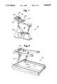
- FIG. 1is a perspective view of an exercise bicycle in accordance with one embodiment of the invention.
- FIG. 2is a perspective view of a exercise treadmill in accordance with one embodiment of the invention.
- FIG. 3is a perspective view of an exercise machine for simulating stair climbing in accordance with one embodiment of the invention
- FIG. 4is a generalized block diagram of an exercise device in accordance with the invention.
- FIG. 5is an illustration of a control and display panel in accordance with one embodiment of the invention.
- FIGS. 6 through 15are logic flow charts of the software program operating in the memory of the microcomputer shown in FIG. 4 which performs the functions specified by the invention.
- a biofeedback-type heart rate management systemwhich provides new, useful features and superior performance.
- FIGS. 1, 2 and 3computer-controlled exercise devices 20, 22, and 24 employing one embodiment of the invention are illustrated. Except for the aspects of the invention described herein, each of the devices 20, 22 and 24 is well-known and commercial available from suppliers such as the Life Fitness of Franklin Park, Ill.
- the device 20is a typical exercise bicycle, and includes a frame 26 on which a user may sit. The user exercises by manipulating pedals 28 in an exercise movement.
- a resistance load device(not illustrated in FIG. 1) is housed within the frame 26 and is coupled to the pedals 28 by a belt, chain or the like. The load device provides a selectively variable resistance to the movement of the pedals 28.
- the load devicemay be mechanical or electromechanical.
- a control panel 30includes a data display 32 and a keypad 34 which enables communication between an internal computer and the user.
- the internal computergenerates a load control signal, which is coupled to the variable load resistance device. Thus, a user may select a particular load level via the keypad 34.
- the internal computerthen generates the appropriate load control signal.
- the bicycle 20also includes a heart rate monitor 36, which is preferably the heart rate detection system disclosed in U.S. patent application Ser. No. 07/722,800, filed Jun. 28, 1991.
- the monitor 36includes four electrodes or "biopotential sensors" 38 which are mounted on a handlebar 40 of the bicycle 20. To engage the monitor 36, a user riding the bicycle 20 touches the electrodes 38 with the palms and fingers of his hands.
- the device 22is a typical treadmill, which includes a frame 42 having an endless belt 44 upon which a user runs or walks.
- the movement of the belt 44serves the same function as the movement of pedals 28 in bicycle 20.
- the treadmill 22also includes a motor which is housed within the frame 42 and is coupled to belt 44.
- the motorunder computer control, drives the belt 44 at a predetermined rate.
- U.S. patent application Ser. No. 07/686,906filed Apr. 17, 1991 and assigned to the assignee of this application.
- the treadmill 22also includes a control panel 46 which enables communication between a computer and the user.
- the computer or usergenerates a speed control signal that controls the speed of the belt 44 of the treadmill 22.
- the computeralso generates an incline control signal which allows the belt 44 to be selectively placed on an incline relative to the horizontal. The steeper the incline, the more intense a user's exercise at a given belt speed. Thus, the incline functions as a load resistance device for providing a selectively variable resistance to the user's exercise movement.
- the treadmill 22also includes a heart rate monitor such as the heart rate monitor 36 of the bicycle 20 (not illustrated).
- device 24is a typical stair climbing simulating machine which includes a frame 48 having vertically reciprocating pedals 50 upon which a user stands to simulate an aerobic stair climbing movement.
- a typical stair climbing simulating machinewhich includes a frame 48 having vertically reciprocating pedals 50 upon which a user stands to simulate an aerobic stair climbing movement.
- the movement of the pedals 50serves a comparable function as the movement of the pedals 28 in bicycle 20 and belt 44 in treadmill 22.
- the stair machine 24also includes a resistance load device which is housed within the frame 48 and is coupled to the pedals 50.
- the load deviceprovides a selectively variable resistance to the movement of the pedals 50.
- the load devicemay be mechanical or electromechanical, and functions to increase the user's exercise intensity. Alternatively, the load device could vary the vertical distance which the pedals 50 reciprocate to provide greater exertion per step.
- the stair climbing machine 24also includes a control panel 51 which enables communication between an internal computer and the user.
- the computergenerates a load control signal, which is coupled to the variable load resistance device.
- the device 24also includes a heart rate monitor (not illustrated in FIG. 3) such as the heart rate sensor monitor 36 of the bicycle 20.
- biofeedback-type devices employing the present inventionmay take a number of forms, including that of each of the devices 20, 22 and 24.
- Each of these devicesincludes a movable member such as pedals 28 or belt 44 which provides the user with an exercise movement The manipulation can be by hand or foot, and may be circular, reciprocating and so forth.
- Each devicealso includes a mechanism for controlling the rate or resistance of the exercise. This mechanism is selectively adjustable to vary the exercise intensity experienced by the user.
- load devicescontemplates any apparatus (such as those described above) which can be used to increase or decrease the intensity of the user's exercise.
- Each device 20, 22 and 24also includes a pulse monitor along with analog or digital processing circuits for comparing the heart rate measured by the pulse sensor to a predetermined or target heart rate.
- heart rateis but one of the physiological indicators of exercise intensity, and for convenience it is used in the foregoing illustrations. It should be understood that the monitors could measure other physiological indicators.
- each device 20, 22 and 24is equipped with a rate sensor (not shown in FIGS. 1-3) measuring rate of exercise activity (e.g., pedal rpm).
- rate of exercise activitye.g., pedal rpm.
- pedal speedwhich are observable outside the body are some indication of the user's exercise intensity, and are referred to as externally observable physical indicators of intensity. They can be thought of as rough approximations of true physiological intensity, which is best measured by a physiological indicator such as heart rate.
- bicycle 20maintains the user's heart rate (or other physiological indicator of exercise intensity) near a target level by adjusting load resistance in response to the user's heart rate.
- the bicycle 20can maintain the user's heart rate near the target level even when heart rate data is unavailable for limited time periods.
- the bicycle 20also uses pedal rpm to supplement the information it receives about heart rate.
- the userbegins an exercise session by entering his age on the keyboard 34 of control panel 30.
- the systemthen computes a target heart
- the usermay designate a target heart rate. The user then enters an initial load level.
- the bicycle 20then sets load resistance at the user-selected load level for a three-minute warm-up period.
- the bicycle 20prompts the user with data display 32 to place his hands on the heart rate sensors 38.
- the user's heart rateis displayed on the data display 32, and the heart rate monitor 36 begins to periodically sample the user's heart rate.
- Bicycle 20adjusts the load in accordance with the user's heart rate to establish the user's heart rate near the target.
- the bicycle 20begins to use pedal rpm (a physical indicator of exercise intensity) to supplement heart rate (a physiological indicator of exercise intensity).
- pedal rpma physical indicator of exercise intensity
- heart ratea physiological indicator of exercise intensity
- physically-based indicators of exercise intensitydo not by themselves provide valid indications of an individual user's true level of physiological intensity. We have realized, however, that physically-based indicators do have value in managing physiological exercise intensity when used in conjunction with the physiological indicators.
- heart rateis used to measure physiological exercise intensity
- pedal rpmis used to measure physical level of exercise intensity.
- pedal rpmcan be effectively used to supplement information provided by heart rate. Because the bicycle's 20 control system has two sources of information about the user's exercise intensity, its performance is improved. If heart rate data is temporarily unavailable, changes in pedal rpm can be used to adjust exercise load to maintain a constant heart rate. Moreover, changes in rpm (i.e., physical or external intensity) tend to anticipate changes in heart rate (i.e., true physiological intensity). By responding to the changes in rpm, load adjustments are made more gradual and heart rate more steady.
- the bicycle 20seeks to continually monitor the user's heart rate. Once the user has reached the target heart rate, however, the bicycle 20 will allow (or, preferably, invite) the user to remove his hands from the sensors 38 for periods of time such as ninety seconds. When the bicycle 20 requires fresh heart rate data, it prompts the user by means of the data display 32. The user then places his hands on the sensors 38 so that the bicycle 20 can take a new sample of heart rate If the user's heart rate is at an appropriate level, the user is again invited to remove his hands from the sensors 38. This cycle is repeated throughout the exercise.
- the systemprompts the user to place his hands on the sensors 38, and the user ignores the prompt for more then forty-five seconds, a bell or beeper is activated. If the user continues to ignore the prompt for an additional fifteen seconds, the load resistance is substantially reduced. It will be observed that during periods where the user's heart rate data is unavailable, the system can use rpm data to maintain the target heart rate.
- FIG. 4is a generalized block diagram of a system 52 in accordance with the preferred embodiment of the invention which is used to implement the foregoing operations of the invention.
- the system 52is illustrated herein as part of exercise bicycle 20.
- system 52can be readily implemented in any of the exercise devices 20, 22 and 24, or in any other type of device providing a variable load resistance or speed control for exercise movement.
- a microcomputer 54controls system 52 and includes a memory 58 and a timer 60.
- the memory 58should include both random access memory as well as read only or non-volatile memory for permanently storing the software programs which enable the microcomputer 54 to perform in accordance with the invention.
- the microcomputer 54can be any suitable device such as the Motorola 68HC05.
- the microcomputer 54communicates with a user via the control panel 30 (illustrated in FIG. 4 by dotted lines), which is described below in greater detail.
- the microcomputer 54controls a load device 62 mounted in the frame 26 (illustrated here by dotted lines). As described above, the load device 62 is operatively associated with the pedals 28 of the system 52 to provide a selectively variable resistance load against the exercise movement of the pedals 28 by the user.
- a device 64 for measuring the rate of exercisewhich is preferably a tachometer, measures the rate of rotation of the pedals 28, and is accessible to the microcomputer 54 by a conventional input/output port.
- the tachometer 64can be implemented by simply measuring the frequency of the output of the alternator. It will be observed that the tachometer 64 measures an externally observable physical indicator of the user's exercise intensity (namely, pedal rpm).
- the interface between the microcomputer 54 and the load device 62should allow the microcomputer 54 to simply write an 8 bit number of between 0 and 250 to an output port 66.
- the numbercorresponds to one of 251 evenly-spaced graduations of load level resistance covering the working range of the load device 62.
- the output of the microprocessor 54 to the port 66 that is used to control the load device 62can be viewed as a load signal. From a programming prospective, the load signal can be represented by the contents of a location in the memory 58.
- a driver routineis then periodically called by an interrupt to write the stored value of load resistance to the port 66.
- the microcomputer 54provides a convenient and practical method of implementing the invention. It will be apparent to those skilled in the art that the logical functions necessary for carrying out the invention could also be implemented using other types of digital and analog circuitry.
- the system 52also includes the heart rate monitor 36 illustrated in FIG. 5 by a dotted line.
- the monitor 36includes a pulse sensor, which may be the electrodes 38 shown in FIG. 1, and a heart rate detector 68.
- a pulse sensorwhich may be the electrodes 38 shown in FIG. 1
- a heart rate detector 68There are numerous commercially available systems for measuring heart rate, but as indicated above, the preferred system is disclosed in U.S. patent application Ser. No. 07/722,800, filed Jun. 28, 1991.
- the heart rate detector 68amplifies and filters the pulse signal received by the sensor 38.
- the pulse signalmay undergo digital signal processing using circuitry within the heart rate monitor 36, or in microprocessor 54 itself. To simply this illustration, it is assumed that all processing of the pulse signal takes place within heart rate monitor 36, which in turn provides an 8 bit value of heart rate over a line 70, and a single bit (the "engagement signal") over a line 72 indicating whether the user is currently engaged with the sensor.
- the engagement signal such as described abovemay be unavailable.
- the system 52can assume that the user is disengaged from the monitor (i.e., by removing his hands, removing an ear clip, or otherwise interrupting the flow of heart rate data) whenever the monitor fails to deliver a heart rate within the range of 50 to 200.
- FIG. 5is a diagram of a control panel which, for the purposes of illustration, is the control panel 30 shown in FIG.
- the control panel 30interfaces with microcomputer 54 in any suitable manner such as by serial or parallel port. Because in practice the microcomputer 54 will control other functions of bicycle 20 in addition to managing heart rate, other features including an elapsed time display and a caloric consumption display are shown in FIG. 5. Contrastingly, in FIG. 4 only selected elements of the control panel 30 are illustrated.
- microcomputer 54For clarity, communication signals between microcomputer 54 and various elements of the control panel 30 are illustrated in FIG. 4 by separate arrows.
- suitable input/output interface circuitrycan be used to facilitate communication between the microcomputer 54 and the control panel 30. As indicated, such communication might involve a serial or parallel link.
- the control panel 30includes the keypad 34, an LED heart rate display 74, an LED heart screen 76, an LED hands-on indicator 78, a high rpm LED 80, a low rpm LED 82, an LED rpm display 84, and an alarm bell 85.
- the specific configuration of the control panel 30, including its layout and the protocol used to communicate with the userare described in connection with the preferred embodiment of the invention as implemented in the exercise system 52.
- the keypad 34is used by the user to communicate with the microcomputer 54.
- a computer controlled exercise bicycle 20has several modes of operation.
- an existing program or mode of operationmight allow the user to pedal at a constant level of load resistance.
- Another modemight enable the user to pedal at randomly selected levels of resistance.
- the present inventionis described as an additional mode of operation which can be referred to as a Heart Rate Management Mode.
- the various modes of operationmay be selected by pressing a select key 86. Each time the select key 86 is pressed, one of the possible modes is selected. A panel 88 above the select key 86 displays indicia of each of the available modes. In the illustration, the available modes are depicted by the indicia "Random”, “Manual” and “Heart [Rate Management]." These a modes are illustrated solely as examples. A small LED next to each indicia indicates when the mode corresponding to the indicia has been selected.
- the LED heart rate display 74displays the current measured value of the user's heart rate when the user has placed his or her hands on the sensors 38. If, for reasons explained below, the user has engaged the sensors 38 but valid heart rate data is not available, then "Hr" or other symbol is displayed in the LED heart rate display 74 to signify that no valid data is yet available.
- the heart-shaped LED hands-on indicator 78is lit by the microcomputer 54 whenever the heart rate monitor 36 signals on the line 72 that the user has engaged the sensors 38. In this case, such engagement is achieved by the user placing his or her hands on the sensors 38.
- this engagementwe refer to this engagement as a hands-on condition, although it to be understood that other types of engagement (such as by ear clip) are contemplated by the invention.
- microcomputer 54enables the heart-shaped LED hands-on indicator 78.
- the heart-shaped LED hands-on indicator 78is lit concurrently with the display of heart rate data (or the "Hr" symbol, as the case may be) in the LED heart rate display 74.
- the LED heart screen 76is preferably an array of LEDs on which a heart 90 or other suitable symbol can be displayed.
- a row 91 of LED'scan be used as a meter to display the relative value of load resistance.
- the heart symbol 90is displayed by microcomputer 54 during those times when the user has his or her hands on the sensors 38. When the heart symbol is not displayed, the user is free to remove his hands from the sensors 38. If the microcomputer 54 determines that the user's current heart rate data is required, and the user's hands are not on the sensors, then the microcomputer 54 can flash the heart symbol to advise the user to place his or her hands on the sensors 38.
- the LED rpm display 84displays the current rpm or other measure of the rate of exercise movement performed by the user.
- the high rpm LED 80 and low rpm LED 82are used to prompt the user to pedal at predetermined high and low rpm levels, respectively.
- the software routines which enable the foregoing operation of the inventionare resident in the memory 58 of microcomputer 54.
- FIGS. 6-15logic flow charts of the software resident in memory 58 are provided. For convenience, selected variable names used in FIGS. 6-15 are included in parentheses throughout this specification.
- the main routine which calls the other major software modulesis illustrated in FIG. 6. Beginning at a block 96, the microcomputer 54 prompts the user to enter his age (AGE). The microprocessor may use the LED heart rate display 74 for prompting, and the user may use the keypad 34 for data entry.
- AGEhis age
- the microprocessormay use the LED heart rate display 74 for prompting, and the user may use the keypad 34 for data entry.
- microcomputer 54computes a target heart rate in accordance with a predetermined formula.
- the target heart rate(HR -- TGT) is set to:
- the usermay enter a target heart rate of his or her own selection.
- the userenters a desired initial exercise load resistance level (LEVEL).
- LEVELinitial exercise load resistance level
- the range of possible exercise levelsis scaled from 0 to 12.
- the microcomputerenters a main driver loop 102 in which the major software modules implementing the invention in the system 52 are called.
- the software resident in the memory 58may include other functions not related to the invention. These functions may be executed in the main driver loop 102, as indicated by a block 104.
- the useris prompted to ride the bicycle 20 for a predetermined warm up period such as three minutes during which time the load level will be established and maintained the constant value LEVEL which the user selected at the block 99.
- a predetermined warm up periodsuch as three minutes during which time the load level will be established and maintained the constant value LEVEL which the user selected at the block 99.
- the major software elements implementing the inventionare the load control module shown in a block 106, the display module shown in a block 108, and the safety module shown in block 110.
- a number of iterations of main driver loop 102will be completed each second.
- the display and safety modules 108 and 110may be executed more frequently.
- An interruptis triggered once per second and sets a flag (not shown).
- the load control module 106is called from the main driver loop 102 only when this flag is set. It will be noted that during the three-minute warm-up, the load control routine is suppressed and is not called with each iteration of the main driver loop 102.
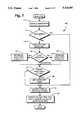
- FIG. 7is a logic flow chart of the load control module 106.
- microcomputer 54interrogates heart rate monitor 36 to determine if a current sample of the user's heart rate is available. If such a sample is available, it is stored in a variable HR -- NEW.
- controlcontinues to a block 116, where the change in load resistance (the "load response") is computed on the basis of the freshly sampled heart rate and other variables as discussed below. Otherwise control skips the block 116 and jumps to a block 130, discussed below.
- controlbranches at a decisional block 120 depending on whether the load response is positive or negative. If load response is negative, then the microcomputer 54 decreases load resistance by calling a decrease load routine shown in a block 122. If load response is positive, then the microcomputer 54 increases load resistance by calling an increase load routine shown in a block 124.
- a boolean flagindicates whether the target heart rate condition exists or has existed.
- the TARGET flagis set at the block 112 as soon as the user's current heart rate is greater than or equal to the target heart rate. Once the target heart rate condition is achieved, the TARGET flag remains set for the duration of the exercise, even if the user's actual heart rate subsequently falls below the target heart rate.
- controlskips to the block 130, discussed below. If the user, however, has attained the target heart rate, then the microcomputer 54 calls a set-hands-off-timer routine shown at block 128 and discussed below in greater detail.
- the hands-off-timer routineexamines the change in the user's heart rate over time, and on the basis of that examination, sets a time period during which the user is free to remove his hands from sensors 38.
- microcomputer 54adjusts load resistance as a function of the change in the user's rpm, as illustrated by the block 130.
- load resistanceAs discussed above, the idea behind adjusting load resistance as a function of RPM is to take advantage of the information about the user's exercise intensity that can be gleaned from rpm.
- microcomputer 54can reduce fluctuations in user heart rate which would otherwise result from the change in pedal rpm.
- system 52can maintain the user's heart rate even when heart rate data is unavailable, such as when the hands-off timer is set. This enables the system 52 to set the hands-off timer (discussed above) for relatively long periods such as ninety seconds. Moreover, the user is free to change the rate of pedaling to make exercise more interesting.
- the microcomputer 54After setting the hands-off timer and adjusting load resistance as a function of rpm, the microcomputer 54 performs housekeeping functions illustrated by the block 126. Specifically, the current values of rpm and heart rate (RPM -- NEW and HR -- NEW) are preserved in memory (in RPM -- OLD and HR -- OLD, respectively) so that the changes in rpm and heart rate may be determined during the next iteration of the load control module 106.
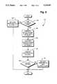
- the load control module 106discussed above are now considered in greater detail Referring to FIG. 8, the sample-heart-rate routine 112 is more fully described.
- the microcomputer 54periodically samples the output of the heart rate monitor 36. It will be noted that the specific techniques disclosed in connection with sample routine 112 have been found to work well, but represent just one of many alternatives which will be readily apparent to those skilled in the art.
- the condition of the engagement signal or "hands-on" bit(provided by the heart rate monitor 36 at the line 72) is determined. If the user is not engaging the sensors 36, it means that no current heart rate data is available. As shown at a block 134, the microcomputer 54 clears the LED heart rate display 74 and disables the LED hands-on indicator 78 of the control panel 30 (as shown in FIG. 5). The microcomputer 54 then sets the new-sample flag (used in connection with the block 114 discussed above) to false, as shown in a block 136.
- the microcomputer 54If, however, the user is engaging the pulse sensors 38 (the "hands-on condition"), then the microcomputer 54 reads the user's heart rate (provided by the heart rate monitor 36 at the line 70), as shown at a block 138. This heart rate is then stored in a memory variable (HR -- NEW) and displayed on the LED heart rate display 74. The LED hands-on indicator 78 is also enabled. Thus, each time the user places his hands on the pulse sensors 38, his heart rate is displayed on control panel 30.
- heart rate monitor 36If, as may be the case initially, the user's hands are on the pulse sensors 38 but heart rate monitor 36 has not yet generated a valid heart rate reading (i.e., a value of between 50 and 200 beats per minute), then the microcomputer 54 generates an "Hr" or other suitable symbol in the LED heart rate display 74.
- microcomputer 54skips to the block 136 where the new sample flag is set to false.
- the heart rate value used to adjust loadis preferably an average of the current and last measured heart rates (HR -- NEW, HR -- OLD).
- HR -- OLDlast measured heart rate
- the microcomputer 54proceeds to a decisional block 144 where it examines the last measured heart rate (HR -- OLD) stored in the memory 58. If the last measured heart rate is invalid, the microcomputer 54 skips to a block 146, where the value of HR -- OLD is updated with the value of HR -- NEW. Control then moves to the block 136, where the new sample flag is set to false.
- the microcomputer 54continues to a block 148, where it increments a counter.
- the function of the counteris to track iterations of the sample heart rate routine 112. Depending on the performance of heart rate monitor 36, it may be desirable to use every other heart rate sample. In this case, if the value of the counter is an even number, then at a block 150 the microcomputer 54 uses the currently measured heart rate to compute an average heart rate, as illustrated at a block 152. Otherwise, the currently measured sample is discarded, and control skips to the block 136, where the new sample flag is set to false.
- Another use of the counteris to suppress the very first sample of heart rate data after the user has placed his hands on the sensors 38. This can be accomplished by setting the counter to -1 at the block 146. In this manner, once heart rate monitor 36 begins delivering valid heart rate data to the microcomputer 54, the first valid sample (corresponding to a counter value of -1) is discarded.
- the average heart rate computed at the block 152is computed by taking the average of the old and current heart rate values (i.e., (HR -- OLD plus HR -- NEW)/2), and storing the result as the current heart rate. By computing this running average, minor aberrations and fluctuations in heart rate data are filtered to improve system stability.
- the microcomputercompares the average computed heart rate (HR -- NEW) to the target heart rate (HR -- TGT) stored in the memory 58, as shown at a block 154. If the average computed heart rate (HR -- NEW) is greater than or equal to the target heart rate, a flag (TARGET) is set true, as illustrated in a block 156. The TARGET flag remains true for the duration of the exercise period, and indicates that the user has reached target heart rate condition.
- the sample-heart-rate routine 124Upon completion of the blocks 156 or 136, as the case may be, the sample-heart-rate routine 124 is terminated, and control returns to the load control module 106 illustrated in FIG. 7. As discussed above, if the sample-heart-rate-routine has successfully acquired a sample heart rate, the new sample flag will be set to true, and, as illustrated in the block 114 of FIG. 7, the microcomputer 54 will proceed to compute a change in the load signal or "load response", as illustrated in the block 116.
- the function of the load response routine 116is to determine a load response, i.e. the amount by which microprocessor 54 changes the value of the load signal 66 to maintain or attain the target heart rate.
- the microprocessor 54first determines at a block 158 whether it is time to update the load signal. While load response can be updated with each iteration of the load response routine, it may be preferably to update less frequently to avoid excessive changes in load resistance. To this end, load response can be updated on each n th iteration, where n is a number such as 6. This can be determined by examining the incremented value of the counter (HR -- CTR) at the block 148 to determine if the counter's current value is a whole number multiple of n.
- microcomputer 54sets the load response variable (D -- LOAD) to zero, as illustrated at a block 160, and terminates the load response routine 116. If it is time to update the load signal 66, then microcomputer 54 calculates the load response (D -- LOAD) as illustrated by blocks 162 through 170 of FIG. 9. First, the actual change (D -- HEART) in the user's heart rate is computed by subtracting the current heart rate value (HR -- NEW) from the old heart rate value (HR -- OLD). Next, the desired change in heart rate (D -- TARGET) is computed by subtracting the target heart rate value (HR -- TGT) from the current heart rate value (HR -- NEW).
- the load response(D -- LOAD) is calculated as the difference between the desired change (D -- TARGET) in heart rate minus the actual change (D -- HEART)in heart rate multiplied by a scaling constant (K 1 ) (i.e., (D -- TARGET-D -- HEART)*K 1 )
- the scaling constant K 1is determined by empirical calibration of the particular device in which the invention is implemented, and simply serves to convert the calculated difference between D -- TARGET and D -- HEART into units of load resistance. In some cases, performance may be improved by weighting D -- TARGET relative to D -- HEART.
- the foregoing techniquecomputes load response as function of the differential in heart rate.
- Other techniques for calculating load response as a function of heart rateare known, and the foregoing is offered as one which we have found particularly effective.
- the inventioncontemplates the use of any suitable technique.
- the load responsecould be computed (albeit less effectively) as a function of the difference between actual and target heart rate.
- the calculated load responseis compared to a predetermined maximum (D -- MAX), as shown in a block 168. If the load response (D -- LOAD) exceeds the predetermined maximum, then load response is set to the predetermined maximum. It will be noted that load response represents the change in load, as opposed to the total magnitude of load. Thus, the predetermined maximum (D -- MAX) does not represent the maximum load to which a user may be subjected, but rather the maximum increase which may be imposed during one iteration of the load control module 106. This prevents load from increasing at an excessive rate which might otherwise prematurely exhaust the user.
- load response(D -- LOAD) is computed at the block 116
- microcomputer 54calculates a scaling factor K 2 , which may simply be a constant such as 1.25.
- the scaling factor K 2is determined by empirical calibration of the particular device in which the invention is implemented, and simply serves to convert the calculated load response (D -- LOAD) into the desired units of load resistance.
- Scaling factor K 2may also be a function of the user-entered load level (LEVEL). It is the case that users who enter high initial load levels typically require more dramatic adjustments to level so as not to overshoot the target heart rate. To compensate for this phenomenon, the scaling factor K 2 may be computed in accordance with the following formula:
- microcomputer 54calculates a scaling factor K 3 .
- the scaling factor K 3is determined by empirical calibration of the particular device in which the invention is implemented, and simply serves to convert the calculated load response (D -- LOAD) into the desired units of load resistance. Scaling factor K 3 may also be set to arbitrarily reduce the load increase. For example, even if the load response does not require scaling, it may be desirable for safety and comfort considerations to use a value of 0.75 for K 3 to reduce the increase load response.
- Microcomputer 54may also reset an rpm overflow counter (RPM -- CTR), as shown in a block 180.
- RPM -- CTRrpm overflow counter
- LOADload resistance in memory 58
- SOFT -- MAXsoft maximum value
- load resistancemay be set equal to the soft maximum, as shown in a block 186.
- the soft maximumis preferably calculated at the beginning of exercise as a function of the user-selected exercise level (LEVEL), which is entered at block 98 of FIG. 6. It will be noted that the difficulty of exercise level (LEVEL) selected by the user is typically indicative of the user's overall fitness level (or at least the user's perceived fitness). Thus, the value of the soft maximum can be higher where the user's has selected a more difficult initial exercise level (LEVEL).
- the load resistancehas a range of 0 through 250 (corresponding to possible numerical values of the load signal), and the user selects an initial load level (LEVEL) of 6 (out of 12), then the user-selected load level could be said to correspond to a load signal of 125 (about one-half of 250).
- the soft maximum (SOFT -- MAX)would be set to 127.
- a user's heart rateis decreasing (i.e., HR -- NEW ⁇ HR -- OLD) even though load resistance has reached the soft maximum.
- HR -- NEW ⁇ HR -- OLDa user's heart rate
- the value of the soft maximumis incremented, such as by one, until the value of the soft maximum reaches a predetermined hard maximum (HARD -- MAX).
- the value of the hard maximumis determined in accordance with the following formula:
- SOFT -- MAXis equal to the initial value of the soft maximum (i.e., user-selected level), and MAX is equal to largest value of load resistance which load device 62 can impose on the user.
- the system 52will tend to establish and maintain the user's heart rate at or near the target heart rate.
- the user's heart rateshould be within 5 beats per minute of the target heart rate.
- the microcomputer 54determines whether a target heart rate condition exists, as shown by block 118. Before a user reaches his target heart rate, it is necessary to closely monitor the user's heart rate so that the appropriate load value can be selected. Once the user reaches his target heart rate, it is no longer necessary to continually monitor heart rate. This is significant because the user may wish to remove his hands from sensors 38.
- the microcomputer 54will determine if it is possible for the user to remove his hands from the pulse sensors 38, and if so, for how long. This determination is performed by the set-hands-off-timer routine shown at the block 128. The details of the set-hands-off-timer routine are illustrated in FIG. 12.
- the microcomputer 54calculates the difference between the actual and desired rates of change in heart rate (D -- TARGET-D -- HEART), as shown in block 192. If the absolute value of the difference is below a predetermined threshold (preferably 8), then control continues to a block 194. Otherwise, the routine terminates.
- a time limitis selected in accordance with the following hands-off time limit table:
- the time limitis set to 15 seconds for the first iteration of the block 194 regardless of the actual difference between D -- HEART and D -- TARGET.
- the selected time limitis used to set the a hands-off timer, which may be a memory location that is periodically decremented by an interrupt generated by the timer 60.
- the contents of the hands-off timer (HR -- TMR) at any given momentrepresent the period of time in seconds remaining in which the user need not engage pulse sensors 38.
- the value contained in the hands-off timeris automatically decremented by one each second.
- the hands-off timeris reset to zero if microcomputer 54 detects a hand-on condition at the block 132.
- the present inventionis by no means limited to heart rate detectors in which the user places his hands on electrodes.
- the foregoing routinesare readily adaptable to any type of system wherein the user somehow engages a pulse sensor.
- a pulse sensorFor example, in a conventional ear-clip type detector, the hands-on signal described above would be replaced by a signal indicating whether the detector was engaged with the user's ear.
- the hands-off timerhas a positive value, the user would be permitted to remove the ear clip.
- the microcomputer 54proceeds to block 130, where the load resistance is adjusted as a function changes in pedal rpm or other measure of the rate of exercise.
- pedal rpmis an externally observable physical indicator of the user's exercise intensity (as opposed to a physiological indicator such as heart rate).
- the rpm-based adjustment at block 130takes place even if no new heart rate data is available (i.e., the new sample condition is false). In this manner, the invention provides for heart rate maintenance even during times when heart rate data is not available.
- microcomputer 54initially reads the current value of rpm from tachometer 64.
- a predetermined thresholdsuch as 6 rpm
- the microcomputer 54determines whether a target heart rate condition has been attained, as shown in the block 200. If the condition has not been attained, the rpm-based adjustment routine 130 terminates without further action. No rpm-based adjustment is required in this case because until the target heart rate has been obtained, the user maintains his hands on the sensors 38, providing a steady stream of heart rate data which can be used by the load response routine 116 to control heart rate.
- the rpm overflow counteris reduced to a value no lower than zero by the amount of the change in rpm (D -- RPM). If the change in rpm is greater than or equal to the value of the rpm overflow counter, then the change in rpm is reduced by the value of the rpm overflow counter,
- the rpm overflow counteris set to zero. Otherwise, the value of the rpm counter is reduced by the change in rpm,
- the resulting value of load resistanceis compared to the current value of the maximum (SOFT -- MAX), as shown in a block 208. If the resulting value of load resistance exceeds the soft maximum, then load resistance is set equal to the soft maximum.
- controlcontinues to a block 210 where the load resistance is adjusted downward by arithmetically subtracting the change in rpm (multiplied by a scaling constant, K 5 , if necessary) to the value of load resistance stored in memory.
- the rpm overflow counterpreserves the amount by which load resistance would otherwise be negative.
- microcomputer 54adds to load resistance on the basis of decreasing rpm (such as at the blocks 204-206)
- itfirst attempts to deplete the overflow represented by the rpm overflow counter, as discussed above. For example, suppose a user accelerates pedaling (i.e., increases rpm) over a period of time, and, at some point during this acceleration, load resistance is driven to zero by repeated iterations of the blocks 210 and 214. Because the rpm overflow counter will contain a nonzero value, the load resistance will not immediately be increased when the user's acceleration peaks and begins to decline. Rather, the load resistance will remain at zero, while the rpm overflow counter absorbs the changes in rpm. When the value of the rpm overflow counter is reduced to zero, successive reductions in pedal rpm will begin to result in higher load resistance.
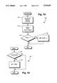
- the display module 108is called with each iteration of the main driver loop 102.
- the display modulemanages the display of information to the user via the control panel 30. Referring to FIG. 14, the operation of the display module 108 is illustrated in greater detail.
- the primary function of the display module 108is to prompt the user when to place his hands on the pulse sensors 38, and to advise the user when he is free to remove his hands.
- the microcomputerdetermines if a hands-on condition exists, as shown at the block 220. If the user's hands are not on the sensors 38, microcomputer 54 sets the LED heart screen 76 to blink, as shown at the block 222. The microcomputer 54 also disables the heart-shaped LED hands-on indicator 78 and clears the LED heart rate display 74. This prompts the user to place his hands on the pulse sensors 38. If, however, the user's hands are already on the sensors 38, then the microcomputer enables the LED hands-on indicator 78, displays the current value of heart rate (HR -- NEW) or the "Hr" symbol on the LED heart rate display 74, and turns on the LED heart screen. It may also be desirable to display the user's heart rate whenever the user touches the pulse sensors, regardless of whether the hands-off timer is zero.
- the display modulealso examines the value of load resistance (LOAD), and determines whether load is at the value of the soft maximum (SOFT -- MAX), or at the value of zero, as shown at the block 228. If the load resistance is equal to the soft maximum, then the TARGET flag is examined at the block 229 to determine if the user has ever reached the target heart rate. If TARGET is false, then the display module terminates. Otherwise, if TARGET is true, then current heart rate is examined to determine if it is less than the target heart rate, as shown in the block 230. If the user has reached the target heart rate, the display module terminates. Otherwise, the current value of rpm is examined, as shown by the block 230.
- LOADload resistance
- SOFT -- MAXsoft maximum
- the high rpm LED 80is enabled. This prompts the user to maintain a pedal rpm near the high level of 100 (indicated by the indicia 92 on panel 30, as shown in FIG. 5). If the user's rpm level is below 98, then the high rpm LED is set to blink so as to prompt the user to increase pedal rpm to 100.
- the display moduleterminates, as shown by the block 234.
- the current value of rpmis examined, as shown by the block 234.
- the block 236if the user's rpm is above 82 then the low rpm LED 82 is set to blink. This prompts the user to reduce pedal rpm to the low rpm level of 80 (indicated by the indicia 94 on panel 30, as shown in FIG. 5). If the user's rpm level is between 77 and 82, the low rpm LED 82 is turned on. This prompts the user to maintain pedal rpm near 80 rpm. If the user's rpm is below 77, the low rpm LED 82 is turned off.
- the safety module 110is called with each iteration of main driver loop 102.
- the function of the safety moduleis to ensure that the system 52 does not continue to operate without sufficient heart rate data.
- the safety features of the present inventiondo not disable the bicycle 20 or even warn the user when the user's heart rate reaches a critical level. Rather, the safety features of the present invention take effect when there is an absence of new heart rate data for a prolonged period of time.
- the microcomputer 54determines whether the hands-off timer (HR -- TMR) is currently set to zero. If not, then it is permissible for the user to have his hands off of the sensors 38, and no further action is necessary.
- the safety moduledisables the bell 85, as shown at a block 242, and terminates.
- the hands-off timeris examined, as shown in a block 244. If the hands-on signal indicates a hands-on condition, then the safety module disables the bell 85, as shown at block 242, and terminates.
- the safety modulesets a safety flag and starts a safety timer, as shown in blocks 246 and 248.
- the safety timermay be implemented using timer 60 of microcomputer 54 in any suitable manner, and in practice is a counter that is periodically incremented by a timer interrupt. The safety timer should not be confused with the hands-off timer.
- the value of the safety timeris examined, as shown in blocks 250-256.
- the microcomputer 54enables the bell 85, as shown in the block 252.
- the beeping soundaugments the flashing LED heart screen (set by the display module 108) to advise the user to place his hands on the pulse sensors 38. If the user does not place his hands on the pulse sensors 38, the safety flag will remain on, and the timer will continue to increment.
- the load resistanceis set to a predetermined value K 6 , which may be zero or other low value of load, as shown in the block 256, to provide the user with additional incentive to place his hands on the sensors 38, and to reduce the risk that the user may attain an excessive heart rate.
Landscapes
- Health & Medical Sciences (AREA)
- Life Sciences & Earth Sciences (AREA)
- Engineering & Computer Science (AREA)
- General Health & Medical Sciences (AREA)
- Physical Education & Sports Medicine (AREA)
- Molecular Biology (AREA)
- Animal Behavior & Ethology (AREA)
- Pathology (AREA)
- Physiology (AREA)
- Biomedical Technology (AREA)
- Heart & Thoracic Surgery (AREA)
- Biophysics (AREA)
- Medical Informatics (AREA)
- Surgery (AREA)
- Physics & Mathematics (AREA)
- Cardiology (AREA)
- Public Health (AREA)
- Veterinary Medicine (AREA)
- Multimedia (AREA)
- Human Computer Interaction (AREA)
- Measuring Pulse, Heart Rate, Blood Pressure Or Blood Flow (AREA)
Abstract
Description
HR.sub.-- TGT=220-AGE*0.7
K.sub.2 =1.25+LEVEL/6.9
HARD.sub.-- MAX=SOFT.sub.-- MAX+(0.25*(MAX-SOFT.sub.-- MAX)),
______________________________________ Time Limit (sec) Difference ______________________________________ 15 6-7 30 4-5 60 2-3 90 0-1 ______________________________________
LOAD=LOAD+(K.sub.4 *D.sub.13 RPM)
D.sub.-- RPM-RPM.sub.-- CTR
RPM.sub.-- CTR=RPM.sub.-- CTR-D.sub.-- RPM,
LOAD=LOAD-(K.sub.5 *D.sub.-- RPM)
Claims (47)
(D.sub.-- TARGET-D.sub.-- HEART)*K;
Priority Applications (9)
| Application Number | Priority Date | Filing Date | Title |
|---|---|---|---|
| US07/881,918US5318487A (en) | 1992-05-12 | 1992-05-12 | Exercise system and method for managing physiological intensity of exercise |
| US07/971,422US5403252A (en) | 1992-05-12 | 1992-11-03 | Exercise apparatus and method for simulating hill climbing |
| EP00107164AEP1029506B1 (en) | 1992-05-12 | 1993-05-07 | Exercise apparatus |
| EP00107165AEP1029507B1 (en) | 1992-05-12 | 1993-05-07 | Exercie apparatus for maintaining a user's level of exercise |
| DE69331819TDE69331819T2 (en) | 1992-05-12 | 1993-05-07 | Exercise system for monitoring the level of physiological exercise |
| DE69333959TDE69333959T2 (en) | 1992-05-12 | 1993-05-07 | Exercise device with means for maintaining the training load of a subject |
| EP93107453AEP0569879B1 (en) | 1992-05-12 | 1993-05-07 | Exercise system for managing physiological intensity of exercise |
| DE69333940TDE69333940T2 (en) | 1992-05-12 | 1993-05-07 | exercise machine |
| CA002095999ACA2095999C (en) | 1992-05-12 | 1993-05-11 | Exercise system and method for managing physiological intensity of exercise |
Applications Claiming Priority (1)
| Application Number | Priority Date | Filing Date | Title |
|---|---|---|---|
| US07/881,918US5318487A (en) | 1992-05-12 | 1992-05-12 | Exercise system and method for managing physiological intensity of exercise |
Related Child Applications (1)
| Application Number | Title | Priority Date | Filing Date |
|---|---|---|---|
| US07/971,422Continuation-In-PartUS5403252A (en) | 1992-05-12 | 1992-11-03 | Exercise apparatus and method for simulating hill climbing |
Publications (1)
| Publication Number | Publication Date |
|---|---|
| US5318487Atrue US5318487A (en) | 1994-06-07 |
Family
ID=25379474
Family Applications (1)
| Application Number | Title | Priority Date | Filing Date |
|---|---|---|---|
| US07/881,918Expired - LifetimeUS5318487A (en) | 1992-05-12 | 1992-05-12 | Exercise system and method for managing physiological intensity of exercise |
Country Status (1)
| Country | Link |
|---|---|
| US (1) | US5318487A (en) |
Cited By (185)
| Publication number | Priority date | Publication date | Assignee | Title |
|---|---|---|---|---|
| US5458548A (en)* | 1993-06-25 | 1995-10-17 | Crossing; Ian F. | Fitness quantification exerciser |
| US5484362A (en)* | 1989-06-19 | 1996-01-16 | Life Fitness | Exercise treadmill |
| US5704875A (en)* | 1994-07-21 | 1998-01-06 | Omron Corporation | Data acquisition device |
| US5738104A (en)* | 1995-11-08 | 1998-04-14 | Salutron, Inc. | EKG based heart rate monitor |
| US5738612A (en)* | 1996-12-04 | 1998-04-14 | Colin Corporation | Exercise apparatus having exercise-load changing function |
| USD394282S (en) | 1996-09-19 | 1998-05-12 | Precor Incorporated | Workout level display indicator |
| US5769755A (en)* | 1995-06-23 | 1998-06-23 | Precor Incorporated | Workout level indicator |
| US5820525A (en)* | 1996-04-12 | 1998-10-13 | Riley; Ronald J. | Treadmill control |
| US5853351A (en)* | 1992-11-16 | 1998-12-29 | Matsushita Electric Works, Ltd. | Method of determining an optimum workload corresponding to user's target heart rate and exercise device therefor |
| USD412192S (en) | 1998-04-23 | 1999-07-20 | Precor Incorporated | Display panel |
| US6026335A (en)* | 1996-07-15 | 2000-02-15 | Atlas; Dan | Heart rate monitor with age-dependent target-zone feedback |
| USD427156S (en)* | 1999-04-19 | 2000-06-27 | Precor Incorporated | Display panel |
| USD438579S1 (en) | 1999-09-03 | 2001-03-06 | Illinois Tool Works Inc. | Control panel |
| USD440612S1 (en) | 2000-04-24 | 2001-04-17 | Illinois Tool Works, Inc. | Display panel extension |
| US6436008B1 (en) | 1989-06-19 | 2002-08-20 | Brunswick Corporation | Exercise treadmill |
| US20020169634A1 (en)* | 2000-12-26 | 2002-11-14 | Kenzo Nishi | Healthcare system, healthcare apparatus, server and healthcare method |
| US6522255B1 (en)* | 1998-03-02 | 2003-02-18 | Steve Hsieh | Handle sensor for detecting signals from human body to a signal processing circuit |
| US20030158692A1 (en)* | 2000-05-08 | 2003-08-21 | Ken Tamada | Human interface method and apparatus |
| US20030181293A1 (en)* | 2002-02-13 | 2003-09-25 | Racer-Mate, Inc. | System and method for verifying the calibration of an exercise apparatus |
| US6626803B1 (en) | 1999-09-07 | 2003-09-30 | Brunswick Corporation | Treadmill control system |
| US6644976B2 (en)* | 2001-09-10 | 2003-11-11 | Epoch Innovations Ltd | Apparatus, method and computer program product to produce or direct movements in synergic timed correlation with physiological activity |
| US6736759B1 (en) | 1999-11-09 | 2004-05-18 | Paragon Solutions, Llc | Exercise monitoring system and methods |
| US20040162188A1 (en)* | 2003-02-14 | 2004-08-19 | Scott Watterson | Progresive heart rate monitor display |
| US20050004483A1 (en)* | 2003-07-03 | 2005-01-06 | Chang Yow Industry Co., Ltd. | Bi-point detection type heart-rate monitor and its heart-rate monitoring method |
| US20050014608A1 (en)* | 2003-07-17 | 2005-01-20 | Chang Yow Industry Co., Ltd. | Handle capable of detecting human physiological characteristics for exercise apparatus |
| US20050209061A1 (en)* | 2003-02-28 | 2005-09-22 | Nautilus, Inc. | Control system and method for an exercise apparatus |
| US20060004265A1 (en)* | 2004-06-16 | 2006-01-05 | Firstbeat Technologies Oy. | System for monitoring and predicting physiological state under physical exercise |
| US7070546B1 (en) | 2002-07-05 | 2006-07-04 | Joseph Grasso | Exercise apparatus including multiple function aspects and small footprint |
| US20060183602A1 (en)* | 2005-02-15 | 2006-08-17 | Astilean Aurel A | System for weight loss and improving physical fitness |
| US20060183603A1 (en)* | 2005-02-15 | 2006-08-17 | Astilean Aurel A | Portable device for weight loss and improving physical fitness and method therefor |
| US7097593B2 (en) | 2003-08-11 | 2006-08-29 | Nautilus, Inc. | Combination of treadmill and stair climbing machine |
| US20060205566A1 (en)* | 1999-07-08 | 2006-09-14 | Watterson Scott R | Systems for interaction with exercise device |
| US20060281603A1 (en)* | 1995-12-14 | 2006-12-14 | Hickman Paul L | Method and apparatus for remote interactive exercise and health equipment |
| US20070135738A1 (en)* | 2003-04-23 | 2007-06-14 | Bonutti Peter M | Patient monitoring apparatus and method for orthosis and other devices |
| US20070149364A1 (en)* | 2005-12-22 | 2007-06-28 | Blau David A | Exercise device |
| EP1834674A2 (en) | 2006-03-13 | 2007-09-19 | Brunswick Corporation | Climber mechanism |
| US20070259763A1 (en)* | 2006-05-05 | 2007-11-08 | Full Potential, Llc | Exercise device and method |
| US20070265138A1 (en)* | 1999-07-08 | 2007-11-15 | Ashby Darren C | Methods and systems for controlling an exercise apparatus using a portable data storage device |
| FR2900830A1 (en)* | 2006-05-10 | 2007-11-16 | Giant Mfg Co Ltd Soc De Droit | Exercise performance monitoring system for exercise cycle, has control unit automatically determining target exercise quantity for user based on specific parameters, detected torque and pulse |
| US20080051261A1 (en)* | 2006-08-25 | 2008-02-28 | Lewis Charles A | Exercise protocols for treadmills and bicycle ergometers for exercise, diagnostics and rehabilitation |
| US20080207401A1 (en)* | 2007-01-31 | 2008-08-28 | Nautilus, Inc. | Group fitness systems and methods |
| US20080242509A1 (en)* | 2007-03-30 | 2008-10-02 | Menektchiev Alexandre K | Methods and apparatus to control workouts on strength machines |
| US20090011907A1 (en)* | 2007-06-27 | 2009-01-08 | Radow Scott B | Stationary Exercise Equipment |
| US7537546B2 (en) | 1999-07-08 | 2009-05-26 | Icon Ip, Inc. | Systems and methods for controlling the operation of one or more exercise devices and providing motivational programming |
| US7549947B2 (en) | 2001-10-19 | 2009-06-23 | Icon Ip, Inc. | Mobile systems and methods for health, exercise and competition |
| US7556590B2 (en) | 1999-07-08 | 2009-07-07 | Icon Ip, Inc. | Systems and methods for enabling two-way communication between one or more exercise devices and computer devices and for enabling users of the one or more exercise devices to competitively exercise |
| US7628730B1 (en) | 1999-07-08 | 2009-12-08 | Icon Ip, Inc. | Methods and systems for controlling an exercise apparatus using a USB compatible portable remote device |
| US20090325766A1 (en)* | 2007-03-19 | 2009-12-31 | Fujitsu Limited | Exercise condition detection apparatus, exercise condition detection program, and exercise condition detection method |
| US20100216601A1 (en)* | 2006-07-04 | 2010-08-26 | Sami Saalasti | Method and system for guiding a person in physical exercise |
| US20100302142A1 (en)* | 1995-11-06 | 2010-12-02 | French Barry J | System and method for tracking and assessing movement skills in multidimensional space |
| US20110034302A1 (en)* | 2009-08-04 | 2011-02-10 | Zlobinsky Rachel | System and method for supervised home care rehabilitation of stroke survivors |
| US20110118086A1 (en)* | 2005-12-22 | 2011-05-19 | Mr. Scott B. Radow | Exercise device |
| US8029415B2 (en) | 1999-07-08 | 2011-10-04 | Icon Ip, Inc. | Systems, methods, and devices for simulating real world terrain on an exercise device |
| US20120122063A1 (en)* | 2009-07-31 | 2012-05-17 | Koninklijke Philips Electronics N.V. | Method and system for providing a training program to a subject |
| US20120196255A1 (en)* | 2005-04-06 | 2012-08-02 | Mark Anthony Clarke | Automated processing of training data |
| US8251874B2 (en) | 2009-03-27 | 2012-08-28 | Icon Health & Fitness, Inc. | Exercise systems for simulating real world terrain |
| US8272996B2 (en) | 2007-03-30 | 2012-09-25 | Nautilus, Inc. | Device and method for limiting travel in an exercise device, and an exercise device including such a limiting device |
| USD682372S1 (en)* | 2011-02-09 | 2013-05-14 | Technogym S.P.A. | Exercise device |
| US8647240B2 (en) | 2010-10-08 | 2014-02-11 | Innovative Applications, Inc. | Exercise device |
| US20140106936A1 (en)* | 2012-10-02 | 2014-04-17 | Andreas Fischer | Stationary training bicycle |
| US8844526B2 (en) | 2012-03-30 | 2014-09-30 | Covidien Lp | Methods and systems for triggering with unknown base flow |
| CN104147761A (en)* | 2014-07-19 | 2014-11-19 | 锦州万得新能源汽车技术有限公司 | Control method for exercise heart rate assistance system |
| US20140364281A1 (en)* | 2013-06-06 | 2014-12-11 | Michael Moschel | Exercise equipment and methods of using the same |
| EP2455146A4 (en)* | 2009-07-16 | 2015-06-03 | Design Park Dev Co Ltd | Self-powered speed racing apparatus |
| US9251719B2 (en) | 2001-02-20 | 2016-02-02 | Adidas Ag | Performance monitoring systems and methods |
| US9352187B2 (en) | 2003-02-28 | 2016-05-31 | Nautilus, Inc. | Dual deck exercise device |
| US9364624B2 (en) | 2011-12-07 | 2016-06-14 | Covidien Lp | Methods and systems for adaptive base flow |
| US20160209225A1 (en)* | 2013-08-15 | 2016-07-21 | Gps Tuner Kft. | Method for planning a route for physical training purposes |
| US9498589B2 (en) | 2011-12-31 | 2016-11-22 | Covidien Lp | Methods and systems for adaptive base flow and leak compensation |
| US20160354636A1 (en)* | 2015-06-04 | 2016-12-08 | Samsung Electronics Co., Ltd. | Method and apparatus for providing exercise program based on feedback |
| US9545540B1 (en) | 2013-06-06 | 2017-01-17 | Dtip.Llc | Exercise equipment and methods of using the same |
| USD783741S1 (en) | 2015-10-14 | 2017-04-11 | Dtip.Llc | Shoulder press bench with foot pedals |
| USD784465S1 (en) | 2015-10-14 | 2017-04-18 | Dtip.Llc | Incline bench press bench with foot pedals |
| USD785107S1 (en) | 2015-10-14 | 2017-04-25 | Dtip.Llc | Incline bench press bench with foot pedals |
| USD785732S1 (en) | 2015-10-14 | 2017-05-02 | Dtip .Llc | Bench press bench with foot pedals |
| US9649458B2 (en) | 2008-09-30 | 2017-05-16 | Covidien Lp | Breathing assistance system with multiple pressure sensors |
| US9682306B2 (en) | 2012-10-19 | 2017-06-20 | Industrial Technology Research Institute | Exercise bike and operation method thereof |
| JP2017169792A (en)* | 2016-03-23 | 2017-09-28 | 三菱電機エンジニアリング株式会社 | Electric training device and exercise control method therefor |
| US9808591B2 (en) | 2014-08-15 | 2017-11-07 | Covidien Lp | Methods and systems for breath delivery synchronization |
| US9878201B1 (en) | 2013-06-06 | 2018-01-30 | Michael Moschel | Exercise equipment and methods of using the same |
| US9919183B1 (en) | 2013-06-06 | 2018-03-20 | Michael Moschel | Exercise equipment and methods of using the same |
| US9925346B2 (en) | 2015-01-20 | 2018-03-27 | Covidien Lp | Systems and methods for ventilation with unknown exhalation flow |
| US9950129B2 (en) | 2014-10-27 | 2018-04-24 | Covidien Lp | Ventilation triggering using change-point detection |
| US9981096B2 (en) | 2013-03-13 | 2018-05-29 | Covidien Lp | Methods and systems for triggering with unknown inspiratory flow |
| US9993683B2 (en) | 2013-06-06 | 2018-06-12 | Michael Moschel | Upper body exercise equipment with lower body pedals and methods of using the same |
| US10149999B2 (en) | 2013-06-06 | 2018-12-11 | Michael Moschel | Lower body exercise equipment with upper body pedals and methods of using the same |
| US10188890B2 (en) | 2013-12-26 | 2019-01-29 | Icon Health & Fitness, Inc. | Magnetic resistance mechanism in a cable machine |
| US10220259B2 (en) | 2012-01-05 | 2019-03-05 | Icon Health & Fitness, Inc. | System and method for controlling an exercise device |
| US10226396B2 (en) | 2014-06-20 | 2019-03-12 | Icon Health & Fitness, Inc. | Post workout massage device |
| US10238911B2 (en) | 2016-07-01 | 2019-03-26 | Woodway Usa, Inc. | Motorized treadmill with motor braking mechanism and methods of operating same |
| US10252109B2 (en) | 2016-05-13 | 2019-04-09 | Icon Health & Fitness, Inc. | Weight platform treadmill |
| US10258828B2 (en) | 2015-01-16 | 2019-04-16 | Icon Health & Fitness, Inc. | Controls for an exercise device |
| US10265566B2 (en) | 2009-03-17 | 2019-04-23 | Woodway Usa, Inc. | Manual treadmill and methods of operating the same |
| US10272317B2 (en) | 2016-03-18 | 2019-04-30 | Icon Health & Fitness, Inc. | Lighted pace feature in a treadmill |
| US10279212B2 (en) | 2013-03-14 | 2019-05-07 | Icon Health & Fitness, Inc. | Strength training apparatus with flywheel and related methods |
| US10293211B2 (en) | 2016-03-18 | 2019-05-21 | Icon Health & Fitness, Inc. | Coordinated weight selection |
| US10343017B2 (en) | 2016-11-01 | 2019-07-09 | Icon Health & Fitness, Inc. | Distance sensor for console positioning |
| US10369449B2 (en) | 2016-09-02 | 2019-08-06 | True Fitness Technology, Inc. | Braking systems for exercise machines |
| US10376736B2 (en) | 2016-10-12 | 2019-08-13 | Icon Health & Fitness, Inc. | Cooling an exercise device during a dive motor runway condition |
| US20190247753A1 (en)* | 2001-03-08 | 2019-08-15 | Brian M. Dugan | Systems and methods for improving fitness equipment and exercise |
| US10391361B2 (en) | 2015-02-27 | 2019-08-27 | Icon Health & Fitness, Inc. | Simulating real-world terrain on an exercise device |
| US10426989B2 (en) | 2014-06-09 | 2019-10-01 | Icon Health & Fitness, Inc. | Cable system incorporated into a treadmill |
| US10433612B2 (en) | 2014-03-10 | 2019-10-08 | Icon Health & Fitness, Inc. | Pressure sensor to quantify work |
| US10441844B2 (en) | 2016-07-01 | 2019-10-15 | Icon Health & Fitness, Inc. | Cooling systems and methods for exercise equipment |
| US10471299B2 (en) | 2016-07-01 | 2019-11-12 | Icon Health & Fitness, Inc. | Systems and methods for cooling internal exercise equipment components |
| US10478660B2 (en) | 2015-05-27 | 2019-11-19 | Woodway Usa, Inc. | Recumbent therapeutic and exercise device |
| US10490051B2 (en) | 2016-02-05 | 2019-11-26 | Logitech Europe S.A. | Method and system for detecting fatigue in an athlete |
| US10493349B2 (en) | 2016-03-18 | 2019-12-03 | Icon Health & Fitness, Inc. | Display on exercise device |
| US10500473B2 (en) | 2016-10-10 | 2019-12-10 | Icon Health & Fitness, Inc. | Console positioning |
| US10543395B2 (en) | 2016-12-05 | 2020-01-28 | Icon Health & Fitness, Inc. | Offsetting treadmill deck weight during operation |
| US10561894B2 (en) | 2016-03-18 | 2020-02-18 | Icon Health & Fitness, Inc. | Treadmill with removable supports |
| US10569121B2 (en) | 2016-12-05 | 2020-02-25 | Icon Health & Fitness, Inc. | Pull cable resistance mechanism in a treadmill |
| US10610725B2 (en) | 2015-04-20 | 2020-04-07 | Crew Innovations, Llc | Apparatus and method for increased realism of training on exercise machines |
| US10625137B2 (en) | 2016-03-18 | 2020-04-21 | Icon Health & Fitness, Inc. | Coordinated displays in an exercise device |
| US10661114B2 (en) | 2016-11-01 | 2020-05-26 | Icon Health & Fitness, Inc. | Body weight lift mechanism on treadmill |
| US10671705B2 (en) | 2016-09-28 | 2020-06-02 | Icon Health & Fitness, Inc. | Customizing recipe recommendations |
| US10668320B2 (en) | 2016-12-05 | 2020-06-02 | Icon Health & Fitness, Inc. | Tread belt locking mechanism |
| US10709926B2 (en) | 2015-10-06 | 2020-07-14 | Woodway Usa, Inc. | Treadmill |
| US10729965B2 (en) | 2017-12-22 | 2020-08-04 | Icon Health & Fitness, Inc. | Audible belt guide in a treadmill |
| US10953305B2 (en) | 2015-08-26 | 2021-03-23 | Icon Health & Fitness, Inc. | Strength exercise mechanisms |
| US11103747B1 (en)* | 2012-02-04 | 2021-08-31 | Thomas Chu-Shan Chuang | Athletic training optimization |
| USD930089S1 (en) | 2019-03-12 | 2021-09-07 | Woodway Usa, Inc. | Treadmill |
| US11123602B2 (en) | 2017-01-03 | 2021-09-21 | True Fitness Technology, Inc. | Mechanical braking system for exercise machines |
| US11179618B2 (en)* | 2019-09-17 | 2021-11-23 | Life Fitness, Llc | Systems and methods for guiding user control of fitness machines |
| CN113974641A (en)* | 2021-11-03 | 2022-01-28 | 毕胜普生物科技有限公司 | Control method and system for load motion device |
| US11298284B2 (en) | 2017-02-10 | 2022-04-12 | Woodway Usa, Inc. | Motorized recumbent therapeutic and exercise device |
| US11324954B2 (en) | 2019-06-28 | 2022-05-10 | Covidien Lp | Achieving smooth breathing by modified bilateral phrenic nerve pacing |
| US11338188B2 (en) | 2018-01-18 | 2022-05-24 | True Fitness Technology, Inc. | Braking mechanism for a self-powered treadmill |
| US11364419B2 (en) | 2019-02-21 | 2022-06-21 | Scott B. Radow | Exercise equipment with music synchronization |
| US11451108B2 (en) | 2017-08-16 | 2022-09-20 | Ifit Inc. | Systems and methods for axial impact resistance in electric motors |
| US11452910B1 (en) | 2012-02-04 | 2022-09-27 | Thomas C. Chuang | Athletic training optimization including lactate threshold |
| US20230107803A1 (en)* | 2006-01-04 | 2023-04-06 | Dugan Health, Llc | Systems and methods for improving fitness equipment and exercise |
| US20230386639A1 (en)* | 2019-10-03 | 2023-11-30 | Rom Technologies, Inc. | System and method for implementing a cardiac rehabilitation protocol by using artificial intelligence and standardized measurements |
| US11915816B2 (en) | 2019-10-03 | 2024-02-27 | Rom Technologies, Inc. | Systems and methods of using artificial intelligence and machine learning in a telemedical environment to predict user disease states |
| US11923057B2 (en) | 2019-10-03 | 2024-03-05 | Rom Technologies, Inc. | Method and system using artificial intelligence to monitor user characteristics during a telemedicine session |
| US11923065B2 (en) | 2019-10-03 | 2024-03-05 | Rom Technologies, Inc. | Systems and methods for using artificial intelligence and machine learning to detect abnormal heart rhythms of a user performing a treatment plan with an electromechanical machine |
| US11942205B2 (en) | 2019-10-03 | 2024-03-26 | Rom Technologies, Inc. | Method and system for using virtual avatars associated with medical professionals during exercise sessions |
| US11955221B2 (en) | 2019-10-03 | 2024-04-09 | Rom Technologies, Inc. | System and method for using AI/ML to generate treatment plans to stimulate preferred angiogenesis |
| US11955218B2 (en) | 2019-10-03 | 2024-04-09 | Rom Technologies, Inc. | System and method for use of telemedicine-enabled rehabilitative hardware and for encouraging rehabilitative compliance through patient-based virtual shared sessions with patient-enabled mutual encouragement across simulated social networks |
| US11955222B2 (en) | 2019-10-03 | 2024-04-09 | Rom Technologies, Inc. | System and method for determining, based on advanced metrics of actual performance of an electromechanical machine, medical procedure eligibility in order to ascertain survivability rates and measures of quality-of-life criteria |
| US11955223B2 (en) | 2019-10-03 | 2024-04-09 | Rom Technologies, Inc. | System and method for using artificial intelligence and machine learning to provide an enhanced user interface presenting data pertaining to cardiac health, bariatric health, pulmonary health, and/or cardio-oncologic health for the purpose of performing preventative actions |
| US11957956B2 (en) | 2019-05-10 | 2024-04-16 | Rehab2Fit Technologies, Inc. | System, method and apparatus for rehabilitation and exercise |
| US11957960B2 (en) | 2019-05-10 | 2024-04-16 | Rehab2Fit Technologies Inc. | Method and system for using artificial intelligence to adjust pedal resistance |
| US11961603B2 (en) | 2019-10-03 | 2024-04-16 | Rom Technologies, Inc. | System and method for using AI ML and telemedicine to perform bariatric rehabilitation via an electromechanical machine |
| US11978559B2 (en) | 2019-10-03 | 2024-05-07 | Rom Technologies, Inc. | Systems and methods for remotely-enabled identification of a user infection |
| US12020799B2 (en) | 2019-10-03 | 2024-06-25 | Rom Technologies, Inc. | Rowing machines, systems including rowing machines, and methods for using rowing machines to perform treatment plans for rehabilitation |
| US12020800B2 (en) | 2019-10-03 | 2024-06-25 | Rom Technologies, Inc. | System and method for using AI/ML and telemedicine to integrate rehabilitation for a plurality of comorbid conditions |
| US12029940B2 (en) | 2019-03-11 | 2024-07-09 | Rom Technologies, Inc. | Single sensor wearable device for monitoring joint extension and flexion |
| US12057237B2 (en) | 2020-04-23 | 2024-08-06 | Rom Technologies, Inc. | Method and system for describing and recommending optimal treatment plans in adaptive telemedical or other contexts |
| US12096997B2 (en) | 2019-10-03 | 2024-09-24 | Rom Technologies, Inc. | Method and system for treating patients via telemedicine using sensor data from rehabilitation or exercise equipment |
| US12100499B2 (en) | 2020-08-06 | 2024-09-24 | Rom Technologies, Inc. | Method and system for using artificial intelligence and machine learning to create optimal treatment plans based on monetary value amount generated and/or patient outcome |
| US12150792B2 (en) | 2019-10-03 | 2024-11-26 | Rom Technologies, Inc. | Augmented reality placement of goniometer or other sensors |
| US12154672B2 (en) | 2019-10-03 | 2024-11-26 | Rom Technologies, Inc. | Method and system for implementing dynamic treatment environments based on patient information |
| US12165768B2 (en) | 2019-10-03 | 2024-12-10 | Rom Technologies, Inc. | Method and system for use of telemedicine-enabled rehabilitative equipment for prediction of secondary disease |
| US12176091B2 (en) | 2019-10-03 | 2024-12-24 | Rom Technologies, Inc. | Systems and methods for using elliptical machine to perform cardiovascular rehabilitation |
| US12176089B2 (en) | 2019-10-03 | 2024-12-24 | Rom Technologies, Inc. | System and method for using AI ML and telemedicine for cardio-oncologic rehabilitation via an electromechanical machine |
| US12183447B2 (en) | 2019-10-03 | 2024-12-31 | Rom Technologies, Inc. | Method and system for creating an immersive enhanced reality-driven exercise experience for a user |
| US12191021B2 (en) | 2019-10-03 | 2025-01-07 | Rom Technologies, Inc. | System and method for use of telemedicine-enabled rehabilitative hardware and for encouragement of rehabilitative compliance through patient-based virtual shared sessions |
| US12191018B2 (en) | 2019-10-03 | 2025-01-07 | Rom Technologies, Inc. | System and method for using artificial intelligence in telemedicine-enabled hardware to optimize rehabilitative routines capable of enabling remote rehabilitative compliance |
| US12217865B2 (en) | 2019-10-03 | 2025-02-04 | Rom Technologies, Inc. | Method and system for enabling physician-smart virtual conference rooms for use in a telehealth context |
| US12220202B2 (en) | 2019-10-03 | 2025-02-11 | Rom Technologies, Inc. | Remote examination through augmented reality |
| US12224052B2 (en) | 2019-10-03 | 2025-02-11 | Rom Technologies, Inc. | System and method for using AI, machine learning and telemedicine for long-term care via an electromechanical machine |
| US12230381B2 (en) | 2019-10-03 | 2025-02-18 | Rom Technologies, Inc. | System and method for an enhanced healthcare professional user interface displaying measurement information for a plurality of users |
| US12226670B2 (en) | 2019-03-11 | 2025-02-18 | Rom Technologies, Inc. | System, method and apparatus for electrically actuated pedal for an exercise or rehabilitation machine |
| US12230382B2 (en) | 2019-10-03 | 2025-02-18 | Rom Technologies, Inc. | Systems and methods for using artificial intelligence and machine learning to predict a probability of an undesired medical event occurring during a treatment plan |
| US12246222B2 (en) | 2019-10-03 | 2025-03-11 | Rom Technologies, Inc. | Method and system for using artificial intelligence to assign patients to cohorts and dynamically controlling a treatment apparatus based on the assignment during an adaptive telemedical session |
| US12249410B2 (en) | 2019-10-03 | 2025-03-11 | Rom Technologies, Inc. | System and method for use of treatment device to reduce pain medication dependency |
| US12257437B2 (en) | 2020-09-30 | 2025-03-25 | Covidien Lp | Intravenous phrenic nerve stimulation lead |
| US12283356B2 (en) | 2019-10-03 | 2025-04-22 | Rom Technologies, Inc. | System and method for processing medical claims using biometric signatures |
| US12285654B2 (en) | 2019-05-10 | 2025-04-29 | Rom Technologies, Inc. | Method and system for using artificial intelligence to interact with a user of an exercise device during an exercise session |
| US12301663B2 (en) | 2019-10-03 | 2025-05-13 | Rom Technologies, Inc. | System and method for transmitting data and ordering asynchronous data |
| US12324961B2 (en) | 2019-05-10 | 2025-06-10 | Rom Technologies, Inc. | Method and system for using artificial intelligence to present a user interface representing a user's progress in various domains |
| US12327623B2 (en) | 2019-10-03 | 2025-06-10 | Rom Technologies, Inc. | System and method for processing medical claims |
| US12340884B2 (en) | 2019-10-03 | 2025-06-24 | Rom Technologies, Inc. | Method and system to analytically optimize telehealth practice-based billing processes and revenue while enabling regulatory compliance |
| US12347543B2 (en) | 2019-10-03 | 2025-07-01 | Rom Technologies, Inc. | Systems and methods for using artificial intelligence to implement a cardio protocol via a relay-based system |
| US12347558B2 (en) | 2019-10-03 | 2025-07-01 | Rom Technologies, Inc. | Method and system for using artificial intelligence and machine learning to provide recommendations to a healthcare provider in or near real-time during a telemedicine session |
| US12357195B2 (en) | 2020-06-26 | 2025-07-15 | Rom Technologies, Inc. | System, method and apparatus for anchoring an electronic device and measuring a joint angle |
| US12367960B2 (en) | 2020-09-15 | 2025-07-22 | Rom Technologies, Inc. | System and method for using AI ML and telemedicine to perform bariatric rehabilitation via an electromechanical machine |
| US12380984B2 (en) | 2019-10-03 | 2025-08-05 | Rom Technologies, Inc. | Systems and methods for using artificial intelligence and machine learning to generate treatment plans having dynamically tailored cardiac protocols for users to manage a state of an electromechanical machine |
| US12390689B2 (en) | 2019-10-21 | 2025-08-19 | Rom Technologies, Inc. | Persuasive motivation for orthopedic treatment |
| US12402805B2 (en) | 2019-09-17 | 2025-09-02 | Rom Technologies, Inc. | Wearable device for coupling to a user, and measuring and monitoring user activity |
| US12420143B1 (en) | 2019-10-03 | 2025-09-23 | Rom Technologies, Inc. | System and method for enabling residentially-based cardiac rehabilitation by using an electromechanical machine and educational content to mitigate risk factors and optimize user behavior |
| US12424319B2 (en) | 2019-11-06 | 2025-09-23 | Rom Technologies, Inc. | System for remote treatment utilizing privacy controls |
| US12420145B2 (en) | 2019-10-03 | 2025-09-23 | Rom Technologies, Inc. | Systems and methods of using artificial intelligence and machine learning for generating alignment plans to align a user with an imaging sensor during a treatment session |
| US12427376B2 (en) | 2019-10-03 | 2025-09-30 | Rom Technologies, Inc. | Systems and methods for an artificial intelligence engine to optimize a peak performance |
Citations (15)
| Publication number | Priority date | Publication date | Assignee | Title |
|---|---|---|---|---|
| US3395698A (en)* | 1965-10-01 | 1968-08-06 | Mc Donnell Douglas Corp | Physiologically paced ergomeric system |
| US3744480A (en)* | 1971-11-29 | 1973-07-10 | Nasa | Ergometer |
| US4112928A (en)* | 1975-09-11 | 1978-09-12 | Keiper Trainingsysteme Gmbh & Co. | Ergometer |
| US4244021A (en)* | 1979-03-02 | 1981-01-06 | Amf Incorporated | Ergometric exerciser |
| US4278095A (en)* | 1977-09-12 | 1981-07-14 | Lapeyre Pierre A | Exercise monitor system and method |
| US4436097A (en)* | 1982-06-07 | 1984-03-13 | Cunningham Patrick J | Cardiovascular exercise apparatus |
| US4678182A (en)* | 1983-07-08 | 1987-07-07 | Combi Co., Ltd. | Bicycle ergometer and eddy current brake therefor |
| US4911427A (en)* | 1984-03-16 | 1990-03-27 | Sharp Kabushiki Kaisha | Exercise and training machine with microcomputer-assisted training guide |
| US4919416A (en)* | 1989-02-14 | 1990-04-24 | Decloux Richard J | Dual facing aerobic exercise machine |
| US4934692A (en)* | 1986-04-29 | 1990-06-19 | Robert M. Greening, Jr. | Exercise apparatus providing resistance variable during operation |
| US4976424A (en)* | 1987-08-25 | 1990-12-11 | Schwinn Bicycle Company | Load control for exercise device |
| US5001632A (en)* | 1989-12-22 | 1991-03-19 | Hall Tipping Justin | Video game difficulty level adjuster dependent upon player's aerobic activity level during exercise |
| US5018726A (en)* | 1989-08-09 | 1991-05-28 | Yorioka Gerald N | Method and apparatus for determining anaerobic capacity |
| US5067710A (en)* | 1989-02-03 | 1991-11-26 | Proform Fitness Products, Inc. | Computerized exercise machine |
| US5104120A (en)* | 1989-02-03 | 1992-04-14 | Proform Fitness Products, Inc. | Exercise machine control system |
- 1992
- 1992-05-12USUS07/881,918patent/US5318487A/ennot_activeExpired - Lifetime
Patent Citations (16)
| Publication number | Priority date | Publication date | Assignee | Title |
|---|---|---|---|---|
| US3395698A (en)* | 1965-10-01 | 1968-08-06 | Mc Donnell Douglas Corp | Physiologically paced ergomeric system |
| US3744480A (en)* | 1971-11-29 | 1973-07-10 | Nasa | Ergometer |
| US4112928A (en)* | 1975-09-11 | 1978-09-12 | Keiper Trainingsysteme Gmbh & Co. | Ergometer |
| US4278095A (en)* | 1977-09-12 | 1981-07-14 | Lapeyre Pierre A | Exercise monitor system and method |
| US4244021A (en)* | 1979-03-02 | 1981-01-06 | Amf Incorporated | Ergometric exerciser |
| US4436097A (en)* | 1982-06-07 | 1984-03-13 | Cunningham Patrick J | Cardiovascular exercise apparatus |
| US4678182A (en)* | 1983-07-08 | 1987-07-07 | Combi Co., Ltd. | Bicycle ergometer and eddy current brake therefor |
| US4817938A (en)* | 1983-07-08 | 1989-04-04 | Combi Co., Ltd. | Bicycle ergometer and eddy current brake therefor |
| US4911427A (en)* | 1984-03-16 | 1990-03-27 | Sharp Kabushiki Kaisha | Exercise and training machine with microcomputer-assisted training guide |
| US4934692A (en)* | 1986-04-29 | 1990-06-19 | Robert M. Greening, Jr. | Exercise apparatus providing resistance variable during operation |
| US4976424A (en)* | 1987-08-25 | 1990-12-11 | Schwinn Bicycle Company | Load control for exercise device |
| US5067710A (en)* | 1989-02-03 | 1991-11-26 | Proform Fitness Products, Inc. | Computerized exercise machine |
| US5104120A (en)* | 1989-02-03 | 1992-04-14 | Proform Fitness Products, Inc. | Exercise machine control system |
| US4919416A (en)* | 1989-02-14 | 1990-04-24 | Decloux Richard J | Dual facing aerobic exercise machine |
| US5018726A (en)* | 1989-08-09 | 1991-05-28 | Yorioka Gerald N | Method and apparatus for determining anaerobic capacity |
| US5001632A (en)* | 1989-12-22 | 1991-03-19 | Hall Tipping Justin | Video game difficulty level adjuster dependent upon player's aerobic activity level during exercise |
Cited By (302)
| Publication number | Priority date | Publication date | Assignee | Title |
|---|---|---|---|---|
| US5752897A (en)* | 1989-06-19 | 1998-05-19 | Brunswick Corporation | Exercise treadmill |
| US5484362A (en)* | 1989-06-19 | 1996-01-16 | Life Fitness | Exercise treadmill |
| US5599259A (en)* | 1989-06-19 | 1997-02-04 | Life Fitness | Exercise treadmill |
| US6095951A (en)* | 1989-06-19 | 2000-08-01 | Brunswick Corporation | Exercise treadmill |
| US6436008B1 (en) | 1989-06-19 | 2002-08-20 | Brunswick Corporation | Exercise treadmill |
| US5853351A (en)* | 1992-11-16 | 1998-12-29 | Matsushita Electric Works, Ltd. | Method of determining an optimum workload corresponding to user's target heart rate and exercise device therefor |
| US5458548A (en)* | 1993-06-25 | 1995-10-17 | Crossing; Ian F. | Fitness quantification exerciser |
| US5704875A (en)* | 1994-07-21 | 1998-01-06 | Omron Corporation | Data acquisition device |
| US5769755A (en)* | 1995-06-23 | 1998-06-23 | Precor Incorporated | Workout level indicator |
| US20100302142A1 (en)* | 1995-11-06 | 2010-12-02 | French Barry J | System and method for tracking and assessing movement skills in multidimensional space |
| US8861091B2 (en) | 1995-11-06 | 2014-10-14 | Impulse Technology Ltd. | System and method for tracking and assessing movement skills in multidimensional space |
| US8503086B2 (en) | 1995-11-06 | 2013-08-06 | Impulse Technology Ltd. | System and method for tracking and assessing movement skills in multidimensional space |
| US5876350A (en)* | 1995-11-08 | 1999-03-02 | Salutron, Inc. | EKG based heart rate monitor with digital filter and enhancement signal processor |
| US5738104A (en)* | 1995-11-08 | 1998-04-14 | Salutron, Inc. | EKG based heart rate monitor |
| US7713171B1 (en)* | 1995-12-14 | 2010-05-11 | Icon Ip, Inc. | Exercise equipment with removable digital script memory |
| US7980996B2 (en)* | 1995-12-14 | 2011-07-19 | Icon Ip, Inc. | Method and apparatus for remote interactive exercise and health equipment |
| US7575536B1 (en)* | 1995-12-14 | 2009-08-18 | Icon Ip, Inc. | Method and apparatus for remote interactive exercise and health equipment |
| US7625315B2 (en) | 1995-12-14 | 2009-12-01 | Icon Ip, Inc. | Exercise and health equipment |
| US8298123B2 (en)* | 1995-12-14 | 2012-10-30 | Icon Health & Fitness, Inc. | Method and apparatus for remote interactive exercise and health equipment |
| US7637847B1 (en) | 1995-12-14 | 2009-12-29 | Icon Ip, Inc. | Exercise system and method with virtual personal trainer forewarning |
| US20110312470A1 (en)* | 1995-12-14 | 2011-12-22 | Hickman Paul L | Method and apparatus for remote interactive exercise and health equipment |
| US7510509B2 (en) | 1995-12-14 | 2009-03-31 | Icon Ip, Inc. | Method and apparatus for remote interactive exercise and health equipment |
| US20060281603A1 (en)* | 1995-12-14 | 2006-12-14 | Hickman Paul L | Method and apparatus for remote interactive exercise and health equipment |
| US5820525A (en)* | 1996-04-12 | 1998-10-13 | Riley; Ronald J. | Treadmill control |
| US6026335A (en)* | 1996-07-15 | 2000-02-15 | Atlas; Dan | Heart rate monitor with age-dependent target-zone feedback |
| USD394282S (en) | 1996-09-19 | 1998-05-12 | Precor Incorporated | Workout level display indicator |
| US5738612A (en)* | 1996-12-04 | 1998-04-14 | Colin Corporation | Exercise apparatus having exercise-load changing function |
| US6522255B1 (en)* | 1998-03-02 | 2003-02-18 | Steve Hsieh | Handle sensor for detecting signals from human body to a signal processing circuit |
| USD412192S (en) | 1998-04-23 | 1999-07-20 | Precor Incorporated | Display panel |
| USD427156S (en)* | 1999-04-19 | 2000-06-27 | Precor Incorporated | Display panel |
| US20060205566A1 (en)* | 1999-07-08 | 2006-09-14 | Watterson Scott R | Systems for interaction with exercise device |
| US7628730B1 (en) | 1999-07-08 | 2009-12-08 | Icon Ip, Inc. | Methods and systems for controlling an exercise apparatus using a USB compatible portable remote device |
| US7455622B2 (en) | 1999-07-08 | 2008-11-25 | Icon Ip, Inc. | Systems for interaction with exercise device |
| US8758201B2 (en) | 1999-07-08 | 2014-06-24 | Icon Health & Fitness, Inc. | Portable physical activity sensing system |
| US8784270B2 (en) | 1999-07-08 | 2014-07-22 | Icon Ip, Inc. | Portable physical activity sensing system |
| US8029415B2 (en) | 1999-07-08 | 2011-10-04 | Icon Ip, Inc. | Systems, methods, and devices for simulating real world terrain on an exercise device |
| US7985164B2 (en) | 1999-07-08 | 2011-07-26 | Icon Ip, Inc. | Methods and systems for controlling an exercise apparatus using a portable data storage device |
| US7981000B2 (en) | 1999-07-08 | 2011-07-19 | Icon Ip, Inc. | Systems for interaction with exercise device |
| US7537546B2 (en) | 1999-07-08 | 2009-05-26 | Icon Ip, Inc. | Systems and methods for controlling the operation of one or more exercise devices and providing motivational programming |
| US7556590B2 (en) | 1999-07-08 | 2009-07-07 | Icon Ip, Inc. | Systems and methods for enabling two-way communication between one or more exercise devices and computer devices and for enabling users of the one or more exercise devices to competitively exercise |
| US8690735B2 (en) | 1999-07-08 | 2014-04-08 | Icon Health & Fitness, Inc. | Systems for interaction with exercise device |
| US9028368B2 (en) | 1999-07-08 | 2015-05-12 | Icon Health & Fitness, Inc. | Systems, methods, and devices for simulating real world terrain on an exercise device |
| US7862478B2 (en) | 1999-07-08 | 2011-01-04 | Icon Ip, Inc. | System and methods for controlling the operation of one or more exercise devices and providing motivational programming |
| US20070265138A1 (en)* | 1999-07-08 | 2007-11-15 | Ashby Darren C | Methods and systems for controlling an exercise apparatus using a portable data storage device |
| US7789800B1 (en) | 1999-07-08 | 2010-09-07 | Icon Ip, Inc. | Methods and systems for controlling an exercise apparatus using a USB compatible portable remote device |
| US7645213B2 (en) | 1999-07-08 | 2010-01-12 | Watterson Scott R | Systems for interaction with exercise device |
| USD438579S1 (en) | 1999-09-03 | 2001-03-06 | Illinois Tool Works Inc. | Control panel |
| US6626803B1 (en) | 1999-09-07 | 2003-09-30 | Brunswick Corporation | Treadmill control system |
| US7220220B2 (en) | 1999-11-09 | 2007-05-22 | Stubbs Jack B | Exercise monitoring system and methods |
| US6736759B1 (en) | 1999-11-09 | 2004-05-18 | Paragon Solutions, Llc | Exercise monitoring system and methods |
| US20040260191A1 (en)* | 1999-11-09 | 2004-12-23 | Stubbs Jack B. | Exercise monitoring system and methods |
| USD440612S1 (en) | 2000-04-24 | 2001-04-17 | Illinois Tool Works, Inc. | Display panel extension |
| US20030158692A1 (en)* | 2000-05-08 | 2003-08-21 | Ken Tamada | Human interface method and apparatus |
| US6931359B2 (en)* | 2000-05-08 | 2005-08-16 | Ken Tamada | Human interface method and apparatus |
| US20020169634A1 (en)* | 2000-12-26 | 2002-11-14 | Kenzo Nishi | Healthcare system, healthcare apparatus, server and healthcare method |
| US9478149B2 (en) | 2001-02-20 | 2016-10-25 | Adidas Ag | Performance monitoring systems and methods |
| US11557388B2 (en) | 2001-02-20 | 2023-01-17 | Adidas Ag | Performance monitoring systems and methods |
| US10943688B2 (en) | 2001-02-20 | 2021-03-09 | Adidas Ag | Performance monitoring systems and methods |
| US9251719B2 (en) | 2001-02-20 | 2016-02-02 | Adidas Ag | Performance monitoring systems and methods |
| US9401098B2 (en) | 2001-02-20 | 2016-07-26 | Adidas Ag | Performance monitoring systems and methods |
| US10991459B2 (en) | 2001-02-20 | 2021-04-27 | Adidas Ag | Performance monitoring systems and methods |
| US10082396B2 (en) | 2001-02-20 | 2018-09-25 | Adidas Ag | Performance monitoring systems and methods |
| US9415267B2 (en) | 2001-02-20 | 2016-08-16 | Adidas Ag | Performance monitoring systems and methods |
| US10060745B2 (en) | 2001-02-20 | 2018-08-28 | Adidas Ag | Performance monitoring systems and methods |
| US9478148B2 (en) | 2001-02-20 | 2016-10-25 | Adidas Ag | Performance monitoring systems and methods |
| US9983007B2 (en) | 2001-02-20 | 2018-05-29 | Adidas Ag | Performance monitoring systems and methods |
| US9489863B2 (en) | 2001-02-20 | 2016-11-08 | Adidas Ag | Performance monitoring systems and methods |
| US9589480B2 (en) | 2001-02-20 | 2017-03-07 | Adidas Ag | Health monitoring systems and methods |
| US9767709B2 (en) | 2001-02-20 | 2017-09-19 | Adidas Ag | Performance monitoring systems and methods |
| US9711062B2 (en) | 2001-02-20 | 2017-07-18 | Adidas Ag | Performance monitoring systems and methods |
| US9683847B2 (en) | 2001-02-20 | 2017-06-20 | Adidas Ag | Performance monitoring systems and methods |
| US9679494B2 (en) | 2001-02-20 | 2017-06-13 | Adidas Ag | Performance monitoring systems and methods |
| US11014002B2 (en)* | 2001-03-08 | 2021-05-25 | Dugan Health, Llc | Systems and methods for improving fitness equipment and exercise |
| US20190247753A1 (en)* | 2001-03-08 | 2019-08-15 | Brian M. Dugan | Systems and methods for improving fitness equipment and exercise |
| US11534692B2 (en)* | 2001-03-08 | 2022-12-27 | Dugan Health, Llc | Systems and methods for improving fitness equipment and exercise |
| US11033822B2 (en) | 2001-03-08 | 2021-06-15 | Dugan Health, Llc | Systems and methods for improving fitness equipment and exercise |
| US6644976B2 (en)* | 2001-09-10 | 2003-11-11 | Epoch Innovations Ltd | Apparatus, method and computer program product to produce or direct movements in synergic timed correlation with physiological activity |
| US7857731B2 (en) | 2001-10-19 | 2010-12-28 | Icon Ip, Inc. | Mobile systems and methods for health, exercise and competition |
| US7549947B2 (en) | 2001-10-19 | 2009-06-23 | Icon Ip, Inc. | Mobile systems and methods for health, exercise and competition |
| US20030181293A1 (en)* | 2002-02-13 | 2003-09-25 | Racer-Mate, Inc. | System and method for verifying the calibration of an exercise apparatus |
| US7311640B2 (en)* | 2002-02-13 | 2007-12-25 | Racer-Mate, Inc. | System and method for verifying the calibration of an exercise apparatus |
| US7070546B1 (en) | 2002-07-05 | 2006-07-04 | Joseph Grasso | Exercise apparatus including multiple function aspects and small footprint |
| US7097588B2 (en)* | 2003-02-14 | 2006-08-29 | Icon Ip, Inc. | Progresive heart rate monitor display |
| US20040162188A1 (en)* | 2003-02-14 | 2004-08-19 | Scott Watterson | Progresive heart rate monitor display |
| US9352187B2 (en) | 2003-02-28 | 2016-05-31 | Nautilus, Inc. | Dual deck exercise device |
| US7815549B2 (en) | 2003-02-28 | 2010-10-19 | Nautilus, Inc. | Control system and method for an exercise apparatus |
| US20050209061A1 (en)* | 2003-02-28 | 2005-09-22 | Nautilus, Inc. | Control system and method for an exercise apparatus |
| US20070135738A1 (en)* | 2003-04-23 | 2007-06-14 | Bonutti Peter M | Patient monitoring apparatus and method for orthosis and other devices |
| US20050004483A1 (en)* | 2003-07-03 | 2005-01-06 | Chang Yow Industry Co., Ltd. | Bi-point detection type heart-rate monitor and its heart-rate monitoring method |
| US20050014608A1 (en)* | 2003-07-17 | 2005-01-20 | Chang Yow Industry Co., Ltd. | Handle capable of detecting human physiological characteristics for exercise apparatus |
| US7097593B2 (en) | 2003-08-11 | 2006-08-29 | Nautilus, Inc. | Combination of treadmill and stair climbing machine |
| US7805186B2 (en)* | 2004-06-16 | 2010-09-28 | Firstbeat Technologies Oy | System for monitoring and predicting physiological state under physical exercise |
| US20060004265A1 (en)* | 2004-06-16 | 2006-01-05 | Firstbeat Technologies Oy. | System for monitoring and predicting physiological state under physical exercise |
| US20060183602A1 (en)* | 2005-02-15 | 2006-08-17 | Astilean Aurel A | System for weight loss and improving physical fitness |
| US7837596B2 (en) | 2005-02-15 | 2010-11-23 | Astilean Aurel A | Portable device for weight loss and improving physical fitness and method therefor |
| US20060183603A1 (en)* | 2005-02-15 | 2006-08-17 | Astilean Aurel A | Portable device for weight loss and improving physical fitness and method therefor |
| US20120196255A1 (en)* | 2005-04-06 | 2012-08-02 | Mark Anthony Clarke | Automated processing of training data |
| US7862476B2 (en)* | 2005-12-22 | 2011-01-04 | Scott B. Radow | Exercise device |
| US20070149364A1 (en)* | 2005-12-22 | 2007-06-28 | Blau David A | Exercise device |
| US20110118086A1 (en)* | 2005-12-22 | 2011-05-19 | Mr. Scott B. Radow | Exercise device |
| US7976434B2 (en)* | 2005-12-22 | 2011-07-12 | Scott B. Radow | Exercise device |
| US11826652B2 (en)* | 2006-01-04 | 2023-11-28 | Dugan Health, Llc | Systems and methods for improving fitness equipment and exercise |
| US12290752B2 (en)* | 2006-01-04 | 2025-05-06 | Dugan Health, Llc | Systems and methods for improving fitness equipment and exercise |
| US20240042325A1 (en)* | 2006-01-04 | 2024-02-08 | Dugan Health, Llc | Systems and methods for improving fitness equipment and exercise |
| US20230107803A1 (en)* | 2006-01-04 | 2023-04-06 | Dugan Health, Llc | Systems and methods for improving fitness equipment and exercise |
| US7594877B2 (en) | 2006-03-13 | 2009-09-29 | Brunswick Corporation | Climber appliance |
| US20070219064A1 (en)* | 2006-03-13 | 2007-09-20 | Anderson Timothy T | Climber mechanism |
| US7771324B2 (en) | 2006-03-13 | 2010-08-10 | Brunswick Corporation | Climber mechanism |
| US20070219063A1 (en)* | 2006-03-13 | 2007-09-20 | Anderson Timothy T | Climber appliance |
| US20070219065A1 (en)* | 2006-03-13 | 2007-09-20 | Anderson Timothy T | Climber apparatus |
| EP1834674A2 (en) | 2006-03-13 | 2007-09-19 | Brunswick Corporation | Climber mechanism |
| US20070259763A1 (en)* | 2006-05-05 | 2007-11-08 | Full Potential, Llc | Exercise device and method |
| FR2900830A1 (en)* | 2006-05-10 | 2007-11-16 | Giant Mfg Co Ltd Soc De Droit | Exercise performance monitoring system for exercise cycle, has control unit automatically determining target exercise quantity for user based on specific parameters, detected torque and pulse |
| US20100216601A1 (en)* | 2006-07-04 | 2010-08-26 | Sami Saalasti | Method and system for guiding a person in physical exercise |
| US20120035021A1 (en)* | 2006-07-04 | 2012-02-09 | Firstbeat Technologies Oy | Method for guiding a person in physical exercise |
| US8465397B2 (en)* | 2006-07-04 | 2013-06-18 | Firstbeat Technologies Oy | Method for guiding a person in physical exercise |
| US8052580B2 (en)* | 2006-07-04 | 2011-11-08 | Firstbeat Technologies Oy | Method and system for guiding a person in physical exercise |
| US20080051261A1 (en)* | 2006-08-25 | 2008-02-28 | Lewis Charles A | Exercise protocols for treadmills and bicycle ergometers for exercise, diagnostics and rehabilitation |
| US20080207401A1 (en)* | 2007-01-31 | 2008-08-28 | Nautilus, Inc. | Group fitness systems and methods |
| US20090325766A1 (en)* | 2007-03-19 | 2009-12-31 | Fujitsu Limited | Exercise condition detection apparatus, exercise condition detection program, and exercise condition detection method |
| US8272996B2 (en) | 2007-03-30 | 2012-09-25 | Nautilus, Inc. | Device and method for limiting travel in an exercise device, and an exercise device including such a limiting device |
| US20080242509A1 (en)* | 2007-03-30 | 2008-10-02 | Menektchiev Alexandre K | Methods and apparatus to control workouts on strength machines |
| US8663071B2 (en) | 2007-03-30 | 2014-03-04 | Nautilus, Inc. | Device and method for limiting travel in an exercise device, and an exercise device including such a limiting device |
| US7833135B2 (en) | 2007-06-27 | 2010-11-16 | Scott B. Radow | Stationary exercise equipment |
| US20090011907A1 (en)* | 2007-06-27 | 2009-01-08 | Radow Scott B | Stationary Exercise Equipment |
| US9649458B2 (en) | 2008-09-30 | 2017-05-16 | Covidien Lp | Breathing assistance system with multiple pressure sensors |
| US10561884B2 (en) | 2009-03-17 | 2020-02-18 | Woodway Usa, Inc. | Manual treadmill and methods of operating the same |
| US12090356B2 (en) | 2009-03-17 | 2024-09-17 | Woodway Usa, Inc. | Manually powered treadmill |
| US11590377B2 (en) | 2009-03-17 | 2023-02-28 | Woodway Usa, Inc. | Manually powered treadmill |
| US12115405B2 (en) | 2009-03-17 | 2024-10-15 | Woodway Usa, Inc. | Treadmill with electromechanical brake |
| US10850150B2 (en) | 2009-03-17 | 2020-12-01 | Woodway Usa, Inc. | Manually powered treadmill with variable braking resistance |
| US10799745B2 (en) | 2009-03-17 | 2020-10-13 | Woodway Usa, Inc. | Manual treadmill and methods of operating the same |
| US11179589B2 (en) | 2009-03-17 | 2021-11-23 | Woodway Usa, Inc. | Treadmill with electromechanical brake |
| US11465005B2 (en) | 2009-03-17 | 2022-10-11 | Woodway Usa, Inc. | Manually powered treadmill |
| US10265566B2 (en) | 2009-03-17 | 2019-04-23 | Woodway Usa, Inc. | Manual treadmill and methods of operating the same |
| US10561883B2 (en) | 2009-03-17 | 2020-02-18 | Woodway Usa, Inc. | Manually powered treadmill with variable braking resistance |
| US10434354B2 (en) | 2009-03-17 | 2019-10-08 | Woodway Usa, Inc. | Power generating manually operated treadmill |
| US8251874B2 (en) | 2009-03-27 | 2012-08-28 | Icon Health & Fitness, Inc. | Exercise systems for simulating real world terrain |
| EP2455146A4 (en)* | 2009-07-16 | 2015-06-03 | Design Park Dev Co Ltd | Self-powered speed racing apparatus |
| US20120122063A1 (en)* | 2009-07-31 | 2012-05-17 | Koninklijke Philips Electronics N.V. | Method and system for providing a training program to a subject |
| US8496564B2 (en) | 2009-08-04 | 2013-07-30 | Rachel ZLOBINSKY | System and method for supervised home care rehabilitation of stroke survivors |
| US20110034302A1 (en)* | 2009-08-04 | 2011-02-10 | Zlobinsky Rachel | System and method for supervised home care rehabilitation of stroke survivors |
| WO2011016024A3 (en)* | 2009-08-04 | 2012-05-03 | Rachel Zlobinsky | System and method for supervised home care rehabilitation of stroke survivors |
| US8647240B2 (en) | 2010-10-08 | 2014-02-11 | Innovative Applications, Inc. | Exercise device |
| USD682372S1 (en)* | 2011-02-09 | 2013-05-14 | Technogym S.P.A. | Exercise device |
| US10543327B2 (en) | 2011-12-07 | 2020-01-28 | Covidien Lp | Methods and systems for adaptive base flow |
| US11497869B2 (en) | 2011-12-07 | 2022-11-15 | Covidien Lp | Methods and systems for adaptive base flow |
| US9364624B2 (en) | 2011-12-07 | 2016-06-14 | Covidien Lp | Methods and systems for adaptive base flow |
| US11833297B2 (en) | 2011-12-31 | 2023-12-05 | Covidien Lp | Methods and systems for adaptive base flow and leak compensation |
| US10709854B2 (en) | 2011-12-31 | 2020-07-14 | Covidien Lp | Methods and systems for adaptive base flow and leak compensation |
| US9498589B2 (en) | 2011-12-31 | 2016-11-22 | Covidien Lp | Methods and systems for adaptive base flow and leak compensation |
| US10220259B2 (en) | 2012-01-05 | 2019-03-05 | Icon Health & Fitness, Inc. | System and method for controlling an exercise device |
| US11452910B1 (en) | 2012-02-04 | 2022-09-27 | Thomas C. Chuang | Athletic training optimization including lactate threshold |
| US11103747B1 (en)* | 2012-02-04 | 2021-08-31 | Thomas Chu-Shan Chuang | Athletic training optimization |
| US12412427B1 (en) | 2012-02-04 | 2025-09-09 | Thomas Chu-Shan Chuang | Athletic training optimization |
| US10029057B2 (en) | 2012-03-30 | 2018-07-24 | Covidien Lp | Methods and systems for triggering with unknown base flow |
| US8844526B2 (en) | 2012-03-30 | 2014-09-30 | Covidien Lp | Methods and systems for triggering with unknown base flow |
| US9314667B2 (en)* | 2012-10-02 | 2016-04-19 | Andreas Fischer | Stationary training bicycle |
| US20140106936A1 (en)* | 2012-10-02 | 2014-04-17 | Andreas Fischer | Stationary training bicycle |
| US9682306B2 (en) | 2012-10-19 | 2017-06-20 | Industrial Technology Research Institute | Exercise bike and operation method thereof |
| US9981096B2 (en) | 2013-03-13 | 2018-05-29 | Covidien Lp | Methods and systems for triggering with unknown inspiratory flow |
| US10279212B2 (en) | 2013-03-14 | 2019-05-07 | Icon Health & Fitness, Inc. | Strength training apparatus with flywheel and related methods |
| US10149999B2 (en) | 2013-06-06 | 2018-12-11 | Michael Moschel | Lower body exercise equipment with upper body pedals and methods of using the same |
| US9993683B2 (en) | 2013-06-06 | 2018-06-12 | Michael Moschel | Upper body exercise equipment with lower body pedals and methods of using the same |
| US9545540B1 (en) | 2013-06-06 | 2017-01-17 | Dtip.Llc | Exercise equipment and methods of using the same |
| US10143875B2 (en)* | 2013-06-06 | 2018-12-04 | Michael Moschel | Exercise Equipment and methods of using the same |
| US20140364281A1 (en)* | 2013-06-06 | 2014-12-11 | Michael Moschel | Exercise equipment and methods of using the same |
| US9919183B1 (en) | 2013-06-06 | 2018-03-20 | Michael Moschel | Exercise equipment and methods of using the same |
| US9878201B1 (en) | 2013-06-06 | 2018-01-30 | Michael Moschel | Exercise equipment and methods of using the same |
| US9829327B2 (en)* | 2013-08-15 | 2017-11-28 | Gps Tuner Kft. | Method for planning a route for physical training purposes |
| US20160209225A1 (en)* | 2013-08-15 | 2016-07-21 | Gps Tuner Kft. | Method for planning a route for physical training purposes |
| US10188890B2 (en) | 2013-12-26 | 2019-01-29 | Icon Health & Fitness, Inc. | Magnetic resistance mechanism in a cable machine |
| US10433612B2 (en) | 2014-03-10 | 2019-10-08 | Icon Health & Fitness, Inc. | Pressure sensor to quantify work |
| US10426989B2 (en) | 2014-06-09 | 2019-10-01 | Icon Health & Fitness, Inc. | Cable system incorporated into a treadmill |
| US10226396B2 (en) | 2014-06-20 | 2019-03-12 | Icon Health & Fitness, Inc. | Post workout massage device |
| CN104147761A (en)* | 2014-07-19 | 2014-11-19 | 锦州万得新能源汽车技术有限公司 | Control method for exercise heart rate assistance system |
| CN104147761B (en)* | 2014-07-19 | 2016-08-31 | 锦州万得新能源汽车技术有限公司 | The control method of exercise heart rate force aid system |
| US9808591B2 (en) | 2014-08-15 | 2017-11-07 | Covidien Lp | Methods and systems for breath delivery synchronization |
| US10864336B2 (en) | 2014-08-15 | 2020-12-15 | Covidien Lp | Methods and systems for breath delivery synchronization |
| US11712174B2 (en) | 2014-10-27 | 2023-08-01 | Covidien Lp | Ventilation triggering |
| US10940281B2 (en) | 2014-10-27 | 2021-03-09 | Covidien Lp | Ventilation triggering |
| US9950129B2 (en) | 2014-10-27 | 2018-04-24 | Covidien Lp | Ventilation triggering using change-point detection |
| US10258828B2 (en) | 2015-01-16 | 2019-04-16 | Icon Health & Fitness, Inc. | Controls for an exercise device |
| US9925346B2 (en) | 2015-01-20 | 2018-03-27 | Covidien Lp | Systems and methods for ventilation with unknown exhalation flow |
| US10391361B2 (en) | 2015-02-27 | 2019-08-27 | Icon Health & Fitness, Inc. | Simulating real-world terrain on an exercise device |
| US10610725B2 (en) | 2015-04-20 | 2020-04-07 | Crew Innovations, Llc | Apparatus and method for increased realism of training on exercise machines |
| US10478660B2 (en) | 2015-05-27 | 2019-11-19 | Woodway Usa, Inc. | Recumbent therapeutic and exercise device |
| US10360806B2 (en)* | 2015-06-04 | 2019-07-23 | Samsung Electronics Co., Ltd. | Method and apparatus for providing exercise program based on feedback |
| US20160354636A1 (en)* | 2015-06-04 | 2016-12-08 | Samsung Electronics Co., Ltd. | Method and apparatus for providing exercise program based on feedback |
| US10953305B2 (en) | 2015-08-26 | 2021-03-23 | Icon Health & Fitness, Inc. | Strength exercise mechanisms |
| US10709926B2 (en) | 2015-10-06 | 2020-07-14 | Woodway Usa, Inc. | Treadmill |
| US11369835B2 (en) | 2015-10-06 | 2022-06-28 | Woodway Usa, Inc. | Configuration of a running surface for a manual treadmill |
| US11826608B2 (en) | 2015-10-06 | 2023-11-28 | Woodway Usa, Inc. | Treadmill with intermediate member |
| US12208306B2 (en) | 2015-10-06 | 2025-01-28 | Woodway Usa, Inc. | Treadmill with intermediate member |
| USD784465S1 (en) | 2015-10-14 | 2017-04-18 | Dtip.Llc | Incline bench press bench with foot pedals |
| USD783741S1 (en) | 2015-10-14 | 2017-04-11 | Dtip.Llc | Shoulder press bench with foot pedals |
| USD785732S1 (en) | 2015-10-14 | 2017-05-02 | Dtip .Llc | Bench press bench with foot pedals |
| USD785107S1 (en) | 2015-10-14 | 2017-04-25 | Dtip.Llc | Incline bench press bench with foot pedals |
| US10490051B2 (en) | 2016-02-05 | 2019-11-26 | Logitech Europe S.A. | Method and system for detecting fatigue in an athlete |
| US10272317B2 (en) | 2016-03-18 | 2019-04-30 | Icon Health & Fitness, Inc. | Lighted pace feature in a treadmill |
| US10493349B2 (en) | 2016-03-18 | 2019-12-03 | Icon Health & Fitness, Inc. | Display on exercise device |
| US10625137B2 (en) | 2016-03-18 | 2020-04-21 | Icon Health & Fitness, Inc. | Coordinated displays in an exercise device |
| US10293211B2 (en) | 2016-03-18 | 2019-05-21 | Icon Health & Fitness, Inc. | Coordinated weight selection |
| US10561894B2 (en) | 2016-03-18 | 2020-02-18 | Icon Health & Fitness, Inc. | Treadmill with removable supports |
| JP2017169792A (en)* | 2016-03-23 | 2017-09-28 | 三菱電機エンジニアリング株式会社 | Electric training device and exercise control method therefor |
| US10252109B2 (en) | 2016-05-13 | 2019-04-09 | Icon Health & Fitness, Inc. | Weight platform treadmill |
| US10238911B2 (en) | 2016-07-01 | 2019-03-26 | Woodway Usa, Inc. | Motorized treadmill with motor braking mechanism and methods of operating same |
| US11420092B2 (en) | 2016-07-01 | 2022-08-23 | Woodway Usa, Inc. | Motorized treadmill with motor braking mechanism and methods of operating same |
| US10471299B2 (en) | 2016-07-01 | 2019-11-12 | Icon Health & Fitness, Inc. | Systems and methods for cooling internal exercise equipment components |
| US10441844B2 (en) | 2016-07-01 | 2019-10-15 | Icon Health & Fitness, Inc. | Cooling systems and methods for exercise equipment |
| US10905914B2 (en) | 2016-07-01 | 2021-02-02 | Woodway Usa, Inc. | Motorized treadmill with motor braking mechanism and methods of operating same |
| US10369449B2 (en) | 2016-09-02 | 2019-08-06 | True Fitness Technology, Inc. | Braking systems for exercise machines |
| US11065526B2 (en) | 2016-09-02 | 2021-07-20 | True Fitness Technology, Inc. | Braking systems for exercise machines |
| US10671705B2 (en) | 2016-09-28 | 2020-06-02 | Icon Health & Fitness, Inc. | Customizing recipe recommendations |
| US10500473B2 (en) | 2016-10-10 | 2019-12-10 | Icon Health & Fitness, Inc. | Console positioning |
| US10376736B2 (en) | 2016-10-12 | 2019-08-13 | Icon Health & Fitness, Inc. | Cooling an exercise device during a dive motor runway condition |
| US10343017B2 (en) | 2016-11-01 | 2019-07-09 | Icon Health & Fitness, Inc. | Distance sensor for console positioning |
| US10661114B2 (en) | 2016-11-01 | 2020-05-26 | Icon Health & Fitness, Inc. | Body weight lift mechanism on treadmill |
| US10543395B2 (en) | 2016-12-05 | 2020-01-28 | Icon Health & Fitness, Inc. | Offsetting treadmill deck weight during operation |
| US10668320B2 (en) | 2016-12-05 | 2020-06-02 | Icon Health & Fitness, Inc. | Tread belt locking mechanism |
| US10569121B2 (en) | 2016-12-05 | 2020-02-25 | Icon Health & Fitness, Inc. | Pull cable resistance mechanism in a treadmill |
| US11123602B2 (en) | 2017-01-03 | 2021-09-21 | True Fitness Technology, Inc. | Mechanical braking system for exercise machines |
| US12168163B2 (en) | 2017-01-03 | 2024-12-17 | True Fitness Technology, Inc. | Mechanical braking system for exercise machines |
| US11298284B2 (en) | 2017-02-10 | 2022-04-12 | Woodway Usa, Inc. | Motorized recumbent therapeutic and exercise device |
| US11451108B2 (en) | 2017-08-16 | 2022-09-20 | Ifit Inc. | Systems and methods for axial impact resistance in electric motors |
| US10729965B2 (en) | 2017-12-22 | 2020-08-04 | Icon Health & Fitness, Inc. | Audible belt guide in a treadmill |
| US11338188B2 (en) | 2018-01-18 | 2022-05-24 | True Fitness Technology, Inc. | Braking mechanism for a self-powered treadmill |
| US11364419B2 (en) | 2019-02-21 | 2022-06-21 | Scott B. Radow | Exercise equipment with music synchronization |
| US12059591B2 (en) | 2019-03-11 | 2024-08-13 | Rom Technologies, Inc. | Bendable sensor device for monitoring joint extension and flexion |
| US12186623B2 (en) | 2019-03-11 | 2025-01-07 | Rom Technologies, Inc. | Monitoring joint extension and flexion using a sensor device securable to an upper and lower limb |
| US12083381B2 (en) | 2019-03-11 | 2024-09-10 | Rom Technologies, Inc. | Bendable sensor device for monitoring joint extension and flexion |
| US12029940B2 (en) | 2019-03-11 | 2024-07-09 | Rom Technologies, Inc. | Single sensor wearable device for monitoring joint extension and flexion |
| US12226671B2 (en) | 2019-03-11 | 2025-02-18 | Rom Technologies, Inc. | System, method and apparatus for electrically actuated pedal for an exercise or rehabilitation machine |
| US12083380B2 (en) | 2019-03-11 | 2024-09-10 | Rom Technologies, Inc. | Bendable sensor device for monitoring joint extension and flexion |
| US12226670B2 (en) | 2019-03-11 | 2025-02-18 | Rom Technologies, Inc. | System, method and apparatus for electrically actuated pedal for an exercise or rehabilitation machine |
| USD1087256S1 (en) | 2019-03-12 | 2025-08-05 | Woodway Usa, Inc. | Treadmill |
| USD1065370S1 (en) | 2019-03-12 | 2025-03-04 | Woodway Usa, Inc. | Treadmill |
| USD930089S1 (en) | 2019-03-12 | 2021-09-07 | Woodway Usa, Inc. | Treadmill |
| US12285654B2 (en) | 2019-05-10 | 2025-04-29 | Rom Technologies, Inc. | Method and system for using artificial intelligence to interact with a user of an exercise device during an exercise session |
| US11957960B2 (en) | 2019-05-10 | 2024-04-16 | Rehab2Fit Technologies Inc. | Method and system for using artificial intelligence to adjust pedal resistance |
| US12324961B2 (en) | 2019-05-10 | 2025-06-10 | Rom Technologies, Inc. | Method and system for using artificial intelligence to present a user interface representing a user's progress in various domains |
| US11957956B2 (en) | 2019-05-10 | 2024-04-16 | Rehab2Fit Technologies, Inc. | System, method and apparatus for rehabilitation and exercise |
| US12036409B2 (en) | 2019-06-28 | 2024-07-16 | Covidien Lp | Achieving smooth breathing by modified bilateral phrenic nerve pacing |
| US11324954B2 (en) | 2019-06-28 | 2022-05-10 | Covidien Lp | Achieving smooth breathing by modified bilateral phrenic nerve pacing |
| US12402805B2 (en) | 2019-09-17 | 2025-09-02 | Rom Technologies, Inc. | Wearable device for coupling to a user, and measuring and monitoring user activity |
| US11865428B2 (en)* | 2019-09-17 | 2024-01-09 | Life Fitness, Llc | Systems and methods for guiding user control of fitness machines |
| US12402804B2 (en) | 2019-09-17 | 2025-09-02 | Rom Technologies, Inc. | Wearable device for coupling to a user, and measuring and monitoring user activity |
| US11179618B2 (en)* | 2019-09-17 | 2021-11-23 | Life Fitness, Llc | Systems and methods for guiding user control of fitness machines |
| US20220080285A1 (en)* | 2019-09-17 | 2022-03-17 | Life Fitness, Llc | Systems and methods for guiding user control of fitness machines |
| US11923065B2 (en) | 2019-10-03 | 2024-03-05 | Rom Technologies, Inc. | Systems and methods for using artificial intelligence and machine learning to detect abnormal heart rhythms of a user performing a treatment plan with an electromechanical machine |
| US12249410B2 (en) | 2019-10-03 | 2025-03-11 | Rom Technologies, Inc. | System and method for use of treatment device to reduce pain medication dependency |
| US12096997B2 (en) | 2019-10-03 | 2024-09-24 | Rom Technologies, Inc. | Method and system for treating patients via telemedicine using sensor data from rehabilitation or exercise equipment |
| US12427376B2 (en) | 2019-10-03 | 2025-09-30 | Rom Technologies, Inc. | Systems and methods for an artificial intelligence engine to optimize a peak performance |
| US12420145B2 (en) | 2019-10-03 | 2025-09-23 | Rom Technologies, Inc. | Systems and methods of using artificial intelligence and machine learning for generating alignment plans to align a user with an imaging sensor during a treatment session |
| US12150792B2 (en) | 2019-10-03 | 2024-11-26 | Rom Technologies, Inc. | Augmented reality placement of goniometer or other sensors |
| US12154672B2 (en) | 2019-10-03 | 2024-11-26 | Rom Technologies, Inc. | Method and system for implementing dynamic treatment environments based on patient information |
| US12165768B2 (en) | 2019-10-03 | 2024-12-10 | Rom Technologies, Inc. | Method and system for use of telemedicine-enabled rehabilitative equipment for prediction of secondary disease |
| US12020800B2 (en) | 2019-10-03 | 2024-06-25 | Rom Technologies, Inc. | System and method for using AI/ML and telemedicine to integrate rehabilitation for a plurality of comorbid conditions |
| US12176091B2 (en) | 2019-10-03 | 2024-12-24 | Rom Technologies, Inc. | Systems and methods for using elliptical machine to perform cardiovascular rehabilitation |
| US12176089B2 (en) | 2019-10-03 | 2024-12-24 | Rom Technologies, Inc. | System and method for using AI ML and telemedicine for cardio-oncologic rehabilitation via an electromechanical machine |
| US12183447B2 (en) | 2019-10-03 | 2024-12-31 | Rom Technologies, Inc. | Method and system for creating an immersive enhanced reality-driven exercise experience for a user |
| US12191021B2 (en) | 2019-10-03 | 2025-01-07 | Rom Technologies, Inc. | System and method for use of telemedicine-enabled rehabilitative hardware and for encouragement of rehabilitative compliance through patient-based virtual shared sessions |
| US12020799B2 (en) | 2019-10-03 | 2024-06-25 | Rom Technologies, Inc. | Rowing machines, systems including rowing machines, and methods for using rowing machines to perform treatment plans for rehabilitation |
| US12191018B2 (en) | 2019-10-03 | 2025-01-07 | Rom Technologies, Inc. | System and method for using artificial intelligence in telemedicine-enabled hardware to optimize rehabilitative routines capable of enabling remote rehabilitative compliance |
| US11978559B2 (en) | 2019-10-03 | 2024-05-07 | Rom Technologies, Inc. | Systems and methods for remotely-enabled identification of a user infection |
| US12217865B2 (en) | 2019-10-03 | 2025-02-04 | Rom Technologies, Inc. | Method and system for enabling physician-smart virtual conference rooms for use in a telehealth context |
| US12220202B2 (en) | 2019-10-03 | 2025-02-11 | Rom Technologies, Inc. | Remote examination through augmented reality |
| US12220201B2 (en) | 2019-10-03 | 2025-02-11 | Rom Technologies, Inc. | Remote examination through augmented reality |
| US12224052B2 (en) | 2019-10-03 | 2025-02-11 | Rom Technologies, Inc. | System and method for using AI, machine learning and telemedicine for long-term care via an electromechanical machine |
| US12230381B2 (en) | 2019-10-03 | 2025-02-18 | Rom Technologies, Inc. | System and method for an enhanced healthcare professional user interface displaying measurement information for a plurality of users |
| US11961603B2 (en) | 2019-10-03 | 2024-04-16 | Rom Technologies, Inc. | System and method for using AI ML and telemedicine to perform bariatric rehabilitation via an electromechanical machine |
| US11955223B2 (en) | 2019-10-03 | 2024-04-09 | Rom Technologies, Inc. | System and method for using artificial intelligence and machine learning to provide an enhanced user interface presenting data pertaining to cardiac health, bariatric health, pulmonary health, and/or cardio-oncologic health for the purpose of performing preventative actions |
| US12230383B2 (en) | 2019-10-03 | 2025-02-18 | Rom Technologies, Inc. | United states systems and methods for using elliptical machine to perform cardiovascular rehabilitation |
| US12230382B2 (en) | 2019-10-03 | 2025-02-18 | Rom Technologies, Inc. | Systems and methods for using artificial intelligence and machine learning to predict a probability of an undesired medical event occurring during a treatment plan |
| US11955222B2 (en) | 2019-10-03 | 2024-04-09 | Rom Technologies, Inc. | System and method for determining, based on advanced metrics of actual performance of an electromechanical machine, medical procedure eligibility in order to ascertain survivability rates and measures of quality-of-life criteria |
| US12246222B2 (en) | 2019-10-03 | 2025-03-11 | Rom Technologies, Inc. | Method and system for using artificial intelligence to assign patients to cohorts and dynamically controlling a treatment apparatus based on the assignment during an adaptive telemedical session |
| US12062425B2 (en)* | 2019-10-03 | 2024-08-13 | Rom Technologies, Inc. | System and method for implementing a cardiac rehabilitation protocol by using artificial intelligence and standardized measurements |
| US12420143B1 (en) | 2019-10-03 | 2025-09-23 | Rom Technologies, Inc. | System and method for enabling residentially-based cardiac rehabilitation by using an electromechanical machine and educational content to mitigate risk factors and optimize user behavior |
| US12283356B2 (en) | 2019-10-03 | 2025-04-22 | Rom Technologies, Inc. | System and method for processing medical claims using biometric signatures |
| US11955218B2 (en) | 2019-10-03 | 2024-04-09 | Rom Technologies, Inc. | System and method for use of telemedicine-enabled rehabilitative hardware and for encouraging rehabilitative compliance through patient-based virtual shared sessions with patient-enabled mutual encouragement across simulated social networks |
| US11955221B2 (en) | 2019-10-03 | 2024-04-09 | Rom Technologies, Inc. | System and method for using AI/ML to generate treatment plans to stimulate preferred angiogenesis |
| US12301663B2 (en) | 2019-10-03 | 2025-05-13 | Rom Technologies, Inc. | System and method for transmitting data and ordering asynchronous data |
| US11942205B2 (en) | 2019-10-03 | 2024-03-26 | Rom Technologies, Inc. | Method and system for using virtual avatars associated with medical professionals during exercise sessions |
| US12327623B2 (en) | 2019-10-03 | 2025-06-10 | Rom Technologies, Inc. | System and method for processing medical claims |
| US12340884B2 (en) | 2019-10-03 | 2025-06-24 | Rom Technologies, Inc. | Method and system to analytically optimize telehealth practice-based billing processes and revenue while enabling regulatory compliance |
| US12347543B2 (en) | 2019-10-03 | 2025-07-01 | Rom Technologies, Inc. | Systems and methods for using artificial intelligence to implement a cardio protocol via a relay-based system |
| US12347558B2 (en) | 2019-10-03 | 2025-07-01 | Rom Technologies, Inc. | Method and system for using artificial intelligence and machine learning to provide recommendations to a healthcare provider in or near real-time during a telemedicine session |
| US12343180B2 (en) | 2019-10-03 | 2025-07-01 | Rom Technologies, Inc. | Augmented reality placement of goniometer or other sensors |
| US20230386639A1 (en)* | 2019-10-03 | 2023-11-30 | Rom Technologies, Inc. | System and method for implementing a cardiac rehabilitation protocol by using artificial intelligence and standardized measurements |
| US12367959B2 (en) | 2019-10-03 | 2025-07-22 | Rom Technologies, Inc. | System and method for using AI/ML to generate treatment plans to stimulate preferred angiogenesis |
| US11915816B2 (en) | 2019-10-03 | 2024-02-27 | Rom Technologies, Inc. | Systems and methods of using artificial intelligence and machine learning in a telemedical environment to predict user disease states |
| US11923057B2 (en) | 2019-10-03 | 2024-03-05 | Rom Technologies, Inc. | Method and system using artificial intelligence to monitor user characteristics during a telemedicine session |
| US12380985B2 (en) | 2019-10-03 | 2025-08-05 | Rom Technologies, Inc. | Method and system for implementing dynamic treatment environments based on patient information |
| US12380984B2 (en) | 2019-10-03 | 2025-08-05 | Rom Technologies, Inc. | Systems and methods for using artificial intelligence and machine learning to generate treatment plans having dynamically tailored cardiac protocols for users to manage a state of an electromechanical machine |
| US12390689B2 (en) | 2019-10-21 | 2025-08-19 | Rom Technologies, Inc. | Persuasive motivation for orthopedic treatment |
| US12424319B2 (en) | 2019-11-06 | 2025-09-23 | Rom Technologies, Inc. | System for remote treatment utilizing privacy controls |
| US12057237B2 (en) | 2020-04-23 | 2024-08-06 | Rom Technologies, Inc. | Method and system for describing and recommending optimal treatment plans in adaptive telemedical or other contexts |
| US12357195B2 (en) | 2020-06-26 | 2025-07-15 | Rom Technologies, Inc. | System, method and apparatus for anchoring an electronic device and measuring a joint angle |
| US12100499B2 (en) | 2020-08-06 | 2024-09-24 | Rom Technologies, Inc. | Method and system for using artificial intelligence and machine learning to create optimal treatment plans based on monetary value amount generated and/or patient outcome |
| US12367960B2 (en) | 2020-09-15 | 2025-07-22 | Rom Technologies, Inc. | System and method for using AI ML and telemedicine to perform bariatric rehabilitation via an electromechanical machine |
| US12257437B2 (en) | 2020-09-30 | 2025-03-25 | Covidien Lp | Intravenous phrenic nerve stimulation lead |
| CN113974641A (en)* | 2021-11-03 | 2022-01-28 | 毕胜普生物科技有限公司 | Control method and system for load motion device |
Similar Documents
| Publication | Publication Date | Title |
|---|---|---|
| US5318487A (en) | Exercise system and method for managing physiological intensity of exercise | |
| EP0569879B1 (en) | Exercise system for managing physiological intensity of exercise | |
| US5362069A (en) | Combination exercise device/video game | |
| US4998725A (en) | Exercise machine controller | |
| US6475115B1 (en) | Computer exercise system | |
| US20080032864A1 (en) | Internet Enabled Motivational Exercise System and Apparatus | |
| EP0975396B1 (en) | Heart rate interval control for cardiopulmonary interval training | |
| US9682306B2 (en) | Exercise bike and operation method thereof | |
| US5527239A (en) | Pulse rate controlled exercise system | |
| US5492514A (en) | Home trainer with biofeedback | |
| US20120040798A1 (en) | Treadmill with Man-Machine Interaction Speed Regulation and Control Method Thereof | |
| US20030069108A1 (en) | Exercise training and monitoring system | |
| US7815547B2 (en) | Exercise system capable of providing heart rate detection warning and control method thereof | |
| US20040171956A1 (en) | Heart rate monitor using color to convey information | |
| EP0117330A2 (en) | Heart rate monitor and method of monitoring fitness | |
| JPH0515457B2 (en) | ||
| US6010430A (en) | Exercise apparatus for use with conventional chairs | |
| JPH0142694B2 (en) | ||
| JP2000051390A (en) | Training management system | |
| JPH0636839Y2 (en) | Aerobic exercise equipment that can measure internal impedance | |
| KR20010103355A (en) | An individual momentum control system | |
| US20040033862A1 (en) | Control console automatically planning a personal exercise program in accordance with the physical condition measured through the whole exercise session | |
| JPH11128397A (en) | Exercise device and program recording medium for exercise device | |
| JPH03195569A (en) | Training system | |
| CN211752388U (en) | Exercise device |
Legal Events
| Date | Code | Title | Description |
|---|---|---|---|
| AS | Assignment | Owner name:LIFE FITNESS Free format text:ASSIGNMENT OF ASSIGNORS INTEREST.;ASSIGNORS:GOLEN, EMIL S.;OGLESBY, GARY E.;ALEXANDER, DONALD J.;REEL/FRAME:006128/0805 Effective date:19920512 | |
| STCF | Information on status: patent grant | Free format text:PATENTED CASE | |
| FEPP | Fee payment procedure | Free format text:PAT HLDR NO LONGER CLAIMS SMALL ENT STAT AS INDIV INVENTOR (ORIGINAL EVENT CODE: LSM1); ENTITY STATUS OF PATENT OWNER: LARGE ENTITY | |
| FPAY | Fee payment | Year of fee payment:4 | |
| AS | Assignment | Owner name:LIFE FITNESS, ILLINOIS Free format text:RELEASE OF SECURITY INTEREST;ASSIGNOR:SPBC, INC.;REEL/FRAME:008732/0762 Effective date:19940610 Owner name:BRUNSWICK CORPORATION, ILLINOIS Free format text:ASSIGNMENT OF ASSIGNORS INTEREST;ASSIGNOR:LIFE FITNESS;REEL/FRAME:008732/0697 Effective date:19970709 | |
| FPAY | Fee payment | Year of fee payment:8 | |
| FPAY | Fee payment | Year of fee payment:12 | |
| AS | Assignment | Owner name:JPMORGAN CHASE BANK, N.A., TEXAS Free format text:SECURITY AGREEMENT;ASSIGNORS:BRUNSWICK CORPORATION;TRITON BOAT COMPANY, L.P.;ATTWOOD CORPORATION;AND OTHERS;REEL/FRAME:022092/0365 Effective date:20081219 Owner name:JPMORGAN CHASE BANK, N.A.,TEXAS Free format text:SECURITY AGREEMENT;ASSIGNORS:BRUNSWICK CORPORATION;TRITON BOAT COMPANY, L.P.;ATTWOOD CORPORATION;AND OTHERS;REEL/FRAME:022092/0365 Effective date:20081219 | |
| AS | Assignment | Owner name:THE BANK OF NEW YORK MELLON TRUST COMPANY, N.A., I Free format text:SECURITY AGREEMENT;ASSIGNORS:BRUNSWICK CORPORATION;ATTWOOD CORPORATION;BOSTON WHALER, INC.;AND OTHERS;REEL/FRAME:023180/0493 Effective date:20090814 Owner name:THE BANK OF NEW YORK MELLON TRUST COMPANY, N.A.,IL Free format text:SECURITY AGREEMENT;ASSIGNORS:BRUNSWICK CORPORATION;ATTWOOD CORPORATION;BOSTON WHALER, INC.;AND OTHERS;REEL/FRAME:023180/0493 Effective date:20090814 | |
| AS | Assignment | Owner name:LAND 'N' SEA DISTRIBUTING, INC., FLORIDA Free format text:RELEASE BY SECURED PARTY;ASSIGNOR:JPMORGAN CHASE BANK, N.A., AS ADMINISTRATIVE AGENT;REEL/FRAME:026026/0001 Effective date:20110321 Owner name:BRUNSWICK FAMILY BOAT CO. INC., WASHINGTON Free format text:RELEASE BY SECURED PARTY;ASSIGNOR:JPMORGAN CHASE BANK, N.A., AS ADMINISTRATIVE AGENT;REEL/FRAME:026026/0001 Effective date:20110321 Owner name:BRUNSWICK LEISURE BOAT COMPANY, LLC, INDIANA Free format text:RELEASE BY SECURED PARTY;ASSIGNOR:JPMORGAN CHASE BANK, N.A., AS ADMINISTRATIVE AGENT;REEL/FRAME:026026/0001 Effective date:20110321 Owner name:TRITON BOAT COMPANY, L.P., TENNESSEE Free format text:RELEASE BY SECURED PARTY;ASSIGNOR:JPMORGAN CHASE BANK, N.A., AS ADMINISTRATIVE AGENT;REEL/FRAME:026026/0001 Effective date:20110321 Owner name:BRUNSWICK COMMERICAL & GOVERNMENT PRODUCTS, INC., Free format text:RELEASE BY SECURED PARTY;ASSIGNOR:JPMORGAN CHASE BANK, N.A., AS ADMINISTRATIVE AGENT;REEL/FRAME:026026/0001 Effective date:20110321 Owner name:BRUNSWICK CORPORATION, ILLINOIS Free format text:RELEASE BY SECURED PARTY;ASSIGNOR:JPMORGAN CHASE BANK, N.A., AS ADMINISTRATIVE AGENT;REEL/FRAME:026026/0001 Effective date:20110321 Owner name:BRUNSWICK BOWLING & BILLIARDS CORPORATION, ILLINOI Free format text:RELEASE BY SECURED PARTY;ASSIGNOR:JPMORGAN CHASE BANK, N.A., AS ADMINISTRATIVE AGENT;REEL/FRAME:026026/0001 Effective date:20110321 Owner name:LUND BOAT COMPANY, MINNESOTA Free format text:RELEASE BY SECURED PARTY;ASSIGNOR:JPMORGAN CHASE BANK, N.A., AS ADMINISTRATIVE AGENT;REEL/FRAME:026026/0001 Effective date:20110321 Owner name:ATTWOOD CORPORATION, MICHIGAN Free format text:RELEASE BY SECURED PARTY;ASSIGNOR:JPMORGAN CHASE BANK, N.A., AS ADMINISTRATIVE AGENT;REEL/FRAME:026026/0001 Effective date:20110321 Owner name:BOSTON WHALER, INC., FLORIDA Free format text:RELEASE BY SECURED PARTY;ASSIGNOR:JPMORGAN CHASE BANK, N.A., AS ADMINISTRATIVE AGENT;REEL/FRAME:026026/0001 Effective date:20110321 | |
| AS | Assignment | Owner name:JPMORGAN CHASE BANK, N.A., AS ADMINISTRATIVE AGENT Free format text:SECURITY AGREEMENT;ASSIGNORS:BRUNSWICK CORPORATION;ATTWOOD CORPORATION;BOSTON WHALER, INC.;AND OTHERS;REEL/FRAME:026072/0239 Effective date:20110321 | |
| AS | Assignment | Owner name:BRUNSWICK CORPORATION, ILLINOIS Free format text:RELEASE BY SECURED PARTY;ASSIGNOR:THE BANK OF NEW YORK MELLON;REEL/FRAME:031973/0242 Effective date:20130717 | |
| AS | Assignment | Owner name:LAND 'N' SEA DISTRIBUTING, INC., ILLINOIS Free format text:RELEASE BY SECURED PARTY;ASSIGNOR:JPMORGAN CHASE BANK, N.A.;REEL/FRAME:034794/0300 Effective date:20141226 Owner name:BRUNSWICK LEISURE BOAT COMPANY, LLC, ILLINOIS Free format text:RELEASE BY SECURED PARTY;ASSIGNOR:JPMORGAN CHASE BANK, N.A.;REEL/FRAME:034794/0300 Effective date:20141226 Owner name:BRUNSWICK FAMILY BOAT CO. INC., ILLINOIS Free format text:RELEASE BY SECURED PARTY;ASSIGNOR:JPMORGAN CHASE BANK, N.A.;REEL/FRAME:034794/0300 Effective date:20141226 Owner name:BOSTON WHALER, INC., ILLINOIS Free format text:RELEASE BY SECURED PARTY;ASSIGNOR:JPMORGAN CHASE BANK, N.A.;REEL/FRAME:034794/0300 Effective date:20141226 Owner name:ATTWOOD CORPORATION, ILLINOIS Free format text:RELEASE BY SECURED PARTY;ASSIGNOR:JPMORGAN CHASE BANK, N.A.;REEL/FRAME:034794/0300 Effective date:20141226 Owner name:BRUNSWICK COMMERCIAL & GOVERNMENT PRODUCTS, INC., Free format text:RELEASE BY SECURED PARTY;ASSIGNOR:JPMORGAN CHASE BANK, N.A.;REEL/FRAME:034794/0300 Effective date:20141226 Owner name:BRUNSWICK CORPORATION, ILLINOIS Free format text:RELEASE BY SECURED PARTY;ASSIGNOR:JPMORGAN CHASE BANK, N.A.;REEL/FRAME:034794/0300 Effective date:20141226 Owner name:LUND BOAT COMPANY, ILLINOIS Free format text:RELEASE BY SECURED PARTY;ASSIGNOR:JPMORGAN CHASE BANK, N.A.;REEL/FRAME:034794/0300 Effective date:20141226 Owner name:BRUNSWICK BOWLING & BILLIARDS CORPORATION, ILLINOI Free format text:RELEASE BY SECURED PARTY;ASSIGNOR:JPMORGAN CHASE BANK, N.A.;REEL/FRAME:034794/0300 Effective date:20141226 |