US5318345A - Tilt back chair and control - Google Patents
Tilt back chair and controlDownload PDFInfo
- Publication number
- US5318345A US5318345AUS07/712,085US71208591AUS5318345AUS 5318345 AUS5318345 AUS 5318345AUS 71208591 AUS71208591 AUS 71208591AUS 5318345 AUS5318345 AUS 5318345A
- Authority
- US
- United States
- Prior art keywords
- support
- seat
- movable
- chair
- pivot axis
- Prior art date
- Legal status (The legal status is an assumption and is not a legal conclusion. Google has not performed a legal analysis and makes no representation as to the accuracy of the status listed.)
- Expired - Lifetime
Links
Images


Classifications
- A—HUMAN NECESSITIES
- A47—FURNITURE; DOMESTIC ARTICLES OR APPLIANCES; COFFEE MILLS; SPICE MILLS; SUCTION CLEANERS IN GENERAL
- A47C—CHAIRS; SOFAS; BEDS
- A47C7/00—Parts, details, or accessories of chairs or stools
- A47C7/002—Chair or stool bases
- A47C7/004—Chair or stool bases for chairs or stools with central column, e.g. office chairs
- A—HUMAN NECESSITIES
- A47—FURNITURE; DOMESTIC ARTICLES OR APPLIANCES; COFFEE MILLS; SPICE MILLS; SUCTION CLEANERS IN GENERAL
- A47C—CHAIRS; SOFAS; BEDS
- A47C1/00—Chairs adapted for special purposes
- A47C1/02—Reclining or easy chairs
- A47C1/031—Reclining or easy chairs having coupled concurrently adjustable supporting parts
- A47C1/032—Reclining or easy chairs having coupled concurrently adjustable supporting parts the parts being movably-coupled seat and back-rest
- A47C1/03255—Reclining or easy chairs having coupled concurrently adjustable supporting parts the parts being movably-coupled seat and back-rest with a central column, e.g. rocking office chairs
- A—HUMAN NECESSITIES
- A47—FURNITURE; DOMESTIC ARTICLES OR APPLIANCES; COFFEE MILLS; SPICE MILLS; SUCTION CLEANERS IN GENERAL
- A47C—CHAIRS; SOFAS; BEDS
- A47C1/00—Chairs adapted for special purposes
- A47C1/02—Reclining or easy chairs
- A47C1/031—Reclining or easy chairs having coupled concurrently adjustable supporting parts
- A47C1/032—Reclining or easy chairs having coupled concurrently adjustable supporting parts the parts being movably-coupled seat and back-rest
- A47C1/03261—Reclining or easy chairs having coupled concurrently adjustable supporting parts the parts being movably-coupled seat and back-rest characterised by elastic means
- A47C1/03266—Reclining or easy chairs having coupled concurrently adjustable supporting parts the parts being movably-coupled seat and back-rest characterised by elastic means with adjustable elasticity
- A—HUMAN NECESSITIES
- A47—FURNITURE; DOMESTIC ARTICLES OR APPLIANCES; COFFEE MILLS; SPICE MILLS; SUCTION CLEANERS IN GENERAL
- A47C—CHAIRS; SOFAS; BEDS
- A47C1/00—Chairs adapted for special purposes
- A47C1/02—Reclining or easy chairs
- A47C1/031—Reclining or easy chairs having coupled concurrently adjustable supporting parts
- A47C1/032—Reclining or easy chairs having coupled concurrently adjustable supporting parts the parts being movably-coupled seat and back-rest
- A47C1/03261—Reclining or easy chairs having coupled concurrently adjustable supporting parts the parts being movably-coupled seat and back-rest characterised by elastic means
- A47C1/03272—Reclining or easy chairs having coupled concurrently adjustable supporting parts the parts being movably-coupled seat and back-rest characterised by elastic means with coil springs
- A47C1/03274—Reclining or easy chairs having coupled concurrently adjustable supporting parts the parts being movably-coupled seat and back-rest characterised by elastic means with coil springs of torsion type
- A—HUMAN NECESSITIES
- A47—FURNITURE; DOMESTIC ARTICLES OR APPLIANCES; COFFEE MILLS; SPICE MILLS; SUCTION CLEANERS IN GENERAL
- A47C—CHAIRS; SOFAS; BEDS
- A47C7/00—Parts, details, or accessories of chairs or stools
- A47C7/02—Seat parts
- A47C7/14—Seat parts of adjustable shape; elastically mounted ; adaptable to a user contour or ergonomic seating positions
Definitions
- This inventionrelates to tilt back chairs of the type having a back, a seat, and a base. More particularly, this invention relates to an improved chair and control suitable for office and other environments.
- the seatprovide independent flexibility of support for the user, particularly at the front portion of the seat, to further accommodate the user in various typical body positions.
- the seatshould accommodate, for example, the user shifting left and right, straightening one leg more than the other, or extending both legs, without putting undue localized pressure on the user's legs.
- the seatshould allow torsional (left-right) flexing of the front portion of the seat, as well as vertical resilience of the front portion for fore-and-aft pitch flexibility.
- the present inventionachieves differential tilt, that is, a greater degree of back tilt to seat tilt, in a chair having separate back and seat supports.
- the chair control mechanismis designed to allow for movement of the chair back and seat in concert with the user's natural body seating and semi-reclining movements, while alleviating the problem known as "shirt pull" found in many prior art chairs. It also provides both torsional and vertical yieldability of the front portion of the seat to further comfortably accommodate various typical user body positions.
- a further advantage of the preferred embodiment as illustratedis that it can be economically manufactured by modifying existing chair tilt control mechanisms, e.g., a known control available from Faultless Caster of Evansville, Ind.
- Another object of the inventionis to provide a chair which alleviates or eliminates the common problem known as "shirt pull.”
- Still another object of the inventionis to provide a chair that moves in concert with the user's natural movements.
- Yet another object of the inventionis to provide a chair that is relatively easy to manufacture yet attractive in appearance.
- a chairhaving a base, a vertical post supported by the base, a chair seat having a rear portion and a front portion, a chair back and a chair control.
- the chair controlcomprises a housing pivotally attached to the vertical post to remain in a predetermined normally horizontal plane, a resilient biasing means mounted in the housing, a seat support structure, a back support structure and a back frame member, or flipper.
- the seat support structuresometimes referred to as the spider, is connected to and supports the chair seat.
- the seat support structureis pivotally attached to the housing at a horizontal axis substantially vertically aligned with the vertical post.
- the back support structurealso referred to as the back upright assembly, is connected to and supports the chair back.
- the back support structureis pivotally connected to the seat support structure at a horizontal axis forward of the vertical post.
- One end of the flippersupports the back support structure.
- a bearing meansis attached to the back support structure and is matingly engaged with the flipper so that the bearing means can slide across a surface of the flipper as the user leans back and forth.
- the other end of the flipperis pivotally attached to the stationary housing.
- a rear portion of the seat supportis connected to a mid-portion of the flipper. Thereby the flipper correlates the tilt of the seat and of the back, providing substantially greater angular movement and displacement of the back than of the seat.
- the resilient biasing meansbiases the chair in an upright, or untilted, position.
- the torsion springcomprises front and rear portions extending substantially perpendicular to the torsional axis. The rear portion of the spring is in contact with the flipper and exerts an upward force on the flipper which biases the chair in an upright position. The front portion of the spring is engaged and held by a tension adjustment bolt.
- the chairalso comprises a spring mount assembly for providing resilient support to the front portion of the seat.
- the spring mount assemblypreferably comprises a pair of compression springs engaged under compression between the underside of the chair seat and the seat support structure.
- the back support structurepreferably comprises a pair of substantially vertical members, a horizontal member interposed between the vertical members, and a pair of substantially parallel horizontal extension arms attached to the ends of the substantially parallel vertical members.
- the bearing meansis attached to the horizontal cross member.
- the base of the chairis covered by a base cover assembly comprising a bottom base cover and a top base cover.
- the bottom base covercomprises a central portion and a plurality of arms extending radially therefrom in registry with the radial legs of the base. Each arm has an upwardly extending tab for engaging the top base cover.
- the central portionhas a generally cylindrical shape defining a generally cylindrical interior and includes a radially inwardly extending protrusion which reduces the cross sectional area of the interior to provide a friction fit between the bottom base cover and the base.
- a rubber ringfits into the space between the base hub and the bottom base cover and provides a second friction lock.
- the top base coverhas a central portion and a plurality of arms extending radially therefrom. Each arm has a downwardly extending slotted tongue which, upon assembly, accommodates a corresponding upwardly extending tab on each leg of the bottom base cover to provide a snap fit between the top and bottom base covers at the outer end of each leg.
- the top base coveralso comprises downwardly extending planar surfaces which help locate the top base cover in relation to the base.
- the central portion of the top base covercomprises a generally circular opening for accommodating the base.
- the central portionincludes tabs extending radially inwardly from the perimeter of the circular opening to provide a friction fit between the top base cover and the base.
- FIG. 1is a front perspective view of a chair embodying the present invention.
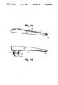
- FIG. 2is a side elevational view of a chair control mechanism embodying the present invention, shown in an untilted position with part of the back support structure cut away.
- FIG. 3is a side elevational view of the chair control mechanism of FIG. 2 in a tilted position.
- FIG. 4is a top elevational view of a chair control mechanism as in FIG. 2, with the back support removed.
- FIG. 5is a side elevational view of a back support structure as in FIG. 2.
- FIG. 6is a bottom view of a chair control mechanism as in FIG. 2.
- FIG. 7is a schematic illustration of a chair control mechanism according to the present invention, with the chair in an upright position.
- FIG. 8is a front perspective view of a chair control mechanism as in FIG. 2.
- FIG. 9is an exploded perspective view of a chair control mechanism as in FIG. 2.
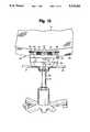
- FIG. 10is a front elevational view of a chair control mechanism embodying the present invention, showing the spring mount assembly.
- FIG. 11is an exploded perspective view of a chair base assembly embodying the present invention.
- FIG. 12is a top view of the top base cover of FIG. 11.
- FIG. 13is a top view of the bottom base cover of FIG. 11.
- FIG. 14is a sectional view of the top base cover of FIG. 12, taken along section 14--14 of FIG. 12.
- FIG. 15is a sectional view of the bottom base cover of FIG. 13, taken along section 15--15 of FIG. 13.
- FIG. 16is an enlarged view of the mating engagement of the bottom base cover and the base shown in FIG. 15.
- FIG. 17is an enlarged view of the mating engagement of the top and bottom base covers shown in FIGS. 14 and 15.
- a chair 10 embodying the present inventionis shown.
- the chairincludes a base 12, a vertical support post or pedestal 14 supported by the base 12, a seat 16 and a back 18.
- a lower back member 20is interposed between the back 18 and seat 16.
- the chair control mechanismdesignated generally as 22 and shown in FIGS. 2-9, is located beneath the seat 16 and is hidden from view in FIG. 1 by the seat and by bottom cover panel 24.
- a lever handle 26engages a height adjustment lever 27 which extends radially from vertical post 14 and can be manipulated by the user to adjust the height of the chair.
- a tension adjustment knob 28can be manipulated by the user to adjust the tension applied to the tilt control, thus increasing or decreasing the resistance to tilt of the chair back and seat relative to the base.
- a tilt lock lever 29, shown in FIG. 10,can be manipulated by the user to place the tilt control mechanism in a locked or unlocked position.
- the base 12comprises a top base cover 30 and a bottom base cover 32 which fit together to form a smooth attractive surface in a manner explained in greater detail below.
- the chair control mechanism 22comprises a housing 34 pivotally attached in a fixed horizontal position on the vertical post 14, a seat support structure 36, a back support structure 38 and a back frame member or flipper 40.
- a resilient biasing means 42comprising a coil spring as best shown in FIGS. 8 and 9, is mounted in the stationary housing 34 and biases the control toward maintaining the chair seat and back in an upright (untilted) position.
- a J-shaped tension bolt 41engages a front portion 42a of the spring, projects through an opening in housing 34, and is adjusted by knob 28 for tension control of the spring 42.
- the seat 16is mounted on and supported by the seat support structure 36. As FIG. 2 shows, and as described further below, the seat support structure 36 is pivotally attached to the stationary housing 34 at horizontal axis A, which is substantially aligned over the vertical post 14.
- the seat support structure 36comprises two substantially parallel horizontal members 48, 50 having front portions 48a, 50a and rear portions 48b, 50b (see FIG. 4).
- the front portionsrefer to those portions forward of the seat pivot axis A
- the rear portionsrefer to those portions rearward of the seat pivot axis A.
- a member 52which is U-shaped in cross-section, extends between and connects the front portions 48a, 50a of the horizontal members 48, 50.
- a flat rigid horizontal cross member 54is fixedly attached to the rear portions 48b, 50b of the horizontal members 48, 50.
- the cross member 54has holes 56, 58 for receiving bolts (not shown) for securing the rear portion of the seat 16 to the seat support structure 36.
- the chair back 18is mounted on and supported by the back support structure 38.
- the back support structure 38is pivotally attached to the seat support structure 36 at axis B which is forward of the vertical post 14.
- the back support structure 38comprises two substantially parallel vertical members 68, 70 and two substantially parallel horizontal members or extension arms 72, 74.
- a horizontal member 76(FIG. 8) connects the vertical members 68, 70.
- the horizontal member 76provides strength and support to the back support structure 38 and also provides a place to attach the bearing pad means 78.
- the back support structure 38is pivotally attached to the seat support structure 36 on a pair of pivot studs 79 which are threaded into nuts 79a that are welded to the sides of the seat support structure 36 (see FIG. 9) at a transverse horizontal axis B located forward of the vertical post 14 to be approximately beneath (in vertical alignment with) the hip joints of a user when in a normal seated position on the chair.
- the rear portion of the back support structure 38is supported by the flipper 40 at the sliding interface of the bearing means 78 and the back plate 44 of the flipper 40.
- the flipper 40comprises a plate 44 at one end for supporting the back support structure 38 at sliding interface C.
- the support plate 44is an extension of the flipper 40 such as by being welded thereto.
- the opposite end 46 of the flipper 40is pivotally attached to the housing 34 at pivot axis D by flipper pivot pin 66 (FIG. 9).
- the flipperis also attached to the seat support structure 36 at slidable pivot connection E in the mid-portion of the flipper.
- An axle pin 60extends through openings in side flanges 40a of the flipper 40 and through slots 61 in the seat support structure 36 (best shown in FIGS. 2 and 3) to secure the flipper 40 to the seat support structure 36 in such a slidable interconnection. This provides a vertical two-way support and load transfer interconnection and interrelation between the tiltable seat support 36 and the tiltable back support structure 38.
- the torsion spring 42rests on a shallow channel "nest" plate 43 which is welded inside the housing 34.
- the springcomprises a coil portion with front arms 42a and rear arms 42b (shown in FIGS. 8 and 9) extending substantially perpendicular to the torsional axis, designated by a T in FIG. 4.
- the rear arms 42b of the torsion spring 42are in contact with a downwardly embossed rib 62 and thereby exert an upward force on the rear portion of the flipper 40.
- the front arm portion 42a of the torsion spring 42is engaged and held by the tension adjustment bolt 41.
- the height adjustment lever 27, shown in FIG. 4,is pivotally supported in one side of the stationary housing 34 and engages a control button 97 at the top of vertical post 14 for selective operation of the pneumatic gas cylinder 98 for adjusting the height of the chair seat 16 in a known manner.
- FIG. 7is a schematic illustration of a chair control mechanism according to the present invention, with the chair shown in an upright position.
- Seat pivot axis Ais shown as being substantially in alignment over vertical post 14.
- Back support structure pivot axis Bis forward of vertical post 14.
- the back support structure 38is supported at C by one end of the flipper 40.
- the opposite end of the flipper 40is pivotally attached to the stationary housing 34 at axis D.
- the flipper 40is also connected to the seat support structure 36 by slidable connection E.
- the torsion spring 42shown schematically, exerts an upward force on the flipper 40 at a location rearward of axis D and thereby biases both the seat and the back to their forward or "upright" position.
- FIG. 9provides an exploded perspective view of the chair control mechanism 22.
- FIG. 9clearly illustrates the manner in which the horizontal members 72, 74 of the back support structure 38 may be connected to the vertical members 68, 70. While the horizontal members 72, 74 are shown welded to the vertical members 68, 70 in the illustrated embodiment, other means for connecting the horizontal members to the vertical members are anticipated, such as bolting the horizontal members to the vertical members, or by making each pair of horizontal and vertical members out of one piece of material. Similarly it will be appreciated that various means of assembly and attachment may be utilized for other components.
- the spring mount assembly 80comprises a pair of coil compression springs 82 supported in the U-shaped member 52, with one spaced at each side of the fore-and-aft centerline of the seat.
- the springs 82are engaged under compression between the underside 84 of the front portion of the chair seat 16 and the U-shaped member 52 for resiliently supporting the front portion of the seat.
- the springsmay be maintained in predetermined positions by being engaged over cylindrical projections or buttons 85 affixed to the seat in appropriate locations, as on a mounting plate 86 affixed to the seat.
- a retention bolt or machine screw 87extends through a larger center opening 88 in member 52 (see FIGS.
- Resilient bumpers 89also are affixed to plate 86 in vertical alignment with the top flanges of the seat support members 48 and 50 to serve as limit stops of this tilting movement.
- the rear portion of the chair seat bottom 84is bolted to the horizontal cross member 54 (shown in FIG. 8).
- the seat bottom 84is made from a resiliently flexible material such as plywood to facilitate fore-and-aft, side-to-side, and diagonal tilting of the seat in concert with the user's movements.
- the flexure of the seatalso is accommodated by rubber bushings in the attachment holes 56, 58 of bar 54, around the respective mounting bolts.
- the tilt lock lever 29 shown in FIG. 10controls the tilting capability of the chair in a known fashion. Specifically, when the tilt lock lever 29 is set in a "locked” position, the lever 29 extends through aligned holes 91 located in the flipper 40 and the housing 34, operately engaging both so as to prevent the flipper 40 and thus the seat and back from tilting with respect to the housing 34. However, when the tilt lock lever 29 is set in an "unlocked” position, the lever 29 is disengaged from these alignment holes, thus allowing the flipper 40 (and consequently the chair back and seat) to move or tilt relative to the housing 34.
- FIG. 11is an exploded elevational view of the base support assembly, designated generally as 90.
- the base support assembly 90comprises a rigid multi-arm base 92 which is covered by top and bottom covers or fairings 94 and 96 respectively, a pneumatic gas cylinder 98, and a gas cylinder cover assembly 100.
- top and bottom base covers 94, 96are secured to the base 92 by means of a friction fit, while the covers themselves are secured to each other by means of a snap fit.
- the top and bottom covers 94, 96fully conceal the base 92, providing a selected finished appearance independent of the structural detail.
- the bottom base cover 96has a central cylindrical portion 102 which itself has a short sleeve portion 103 extending inward from its distal end and which terminates at a constricted inner gripping lip or ring 104.
- the ring 104is defined by an inwardly exposed taper surface 104a and a radial surface 104b.
- the constricted ring portion 104provides a friction fit with the base 92.
- the shape of the ring 104provides ease of assembly of the cover in force-fit relation to a cylindrical portion of the base 92 and firm retention of the bottom cover 96 on the base 92 thereafter.
- a bottom resilient ring 106is then friction fitted around the bottom of the base 92, beneath the radial surface 104b, to help secure the base cover 96 to the base 92 by preventing the bottom base cover 96 from dropping down.
- the top base cover 98is coextensive with and fits over and forms a mating closure with the bottom cover 96.
- the top coverincludes vertical ribs 108 which, upon assembly, fit over the arms of the base 92 to locate the cover in its correct position with respect to the base 92.
- the top base cover 98has a central opening 110 for accommodating the central cylindrical portion 111 of the base 92.
- a plurality of radially inwardly extending cantilever tabs or projections 112engage the central cylindrical portion 111 of the base 92 in a tight friction fit for location and for retention.
- the bottom base cover 96also has an upwardly extending resilient latch tab 114 in each of its radially projecting arms. To engage these tabs 114, each arm of the top base cover 94 has a downwardly extending resilient tapered latch tongue 116 with an aperture 118 to receive the latch head 120 of the respective tab 114 and provide a shoulder 122 for abutting retentive engagement with the lateral latch surface 124 of the respective head 120. Thus, upon assembly, the tabs 114 fit within the slots of the slotted tongues 116 to form a snap fit. In the illustrated embodiment, there are five pairs of tabs and latch tongues, one pair for each of the five arms.
- the top base cover 94is fitted to the base 92 by means of a friction fit.
- the bottom base cover 94is also fitted to the base 92 by means of a friction fit, while the upwardly extending latch tabs 114 engage the downwardly extending latch tongues 116 of the top base cover to form a snap fit between the top and bottom base covers.
- a small washer 128fits over the shaft at the bottom of the gas cylinder assembly 98.
- a clip 130engages a groove in the shaft.
- the resilient base ring 106is fitted to the base 92 to help hold the bottom base cover in place. After the bottom base cover is fitted to the base, the casters 126 are put on.
- a hub liner 132fits within the central opening of the base 92.
- a first large washer 134, a bearing 136, a second large washer 138 and a rubber cushion 140 respectivelyare interposed between the hub liner 132 and the large diameter portion of the gas cylinder 98.
- a multi-section freely telescoping pedestal cover 100fits over the gas cylinder 98, hiding it from view and providing an attractive appearance.
- Flexible snap tabs 101 in the lower end of the cover 100engage slots 105 located around the center of the top base cover.
- a foam filler piece 142is interposed between the pedestal cover 100 and the gas cylinder 98.
- the back support structure 38bears down on the flipper 40 at interface C and/or the seat support structure 36 bears down on the flipper 40 at interface E, causing the flipper 40 to rotate about axis D. That is, in the tilted back position, the flipper 40 is deflected downward. As the flipper 40 is deflected downward, the seat support structure 36 is rotated about the seat pivot axis A in a predetermined relationship because of the vertical interengagement effected between the seat support structure 36 and the flipper 40 by the pin 60 in slots 61.
- the equal vertical movement of the flipper 40 and the rear portion of the seat at the interconnection Eresults in substantially greater angular movement of the flipper 40 than of the seat support 36 because of the difference in effective length of the respective radii or "links" D-E and A-E. Also, because the distance D-C substantially exceeds distance D-E (more than double) the flipper provides much greater vertical displacement of the support C than of the rear end portion of seat support 36 at E. Consequently, the back support structure 38 and hence the chair back 18 have a correspondingly greater vertical movement than the rear portion of the seat 16. In this regard, the lower back member 20 also is fixed relative to the supports 68, 70 and moves vertically therewith adjacent the rear edge of the seat 16.
- the torsion spring 42resists the rearward tilting of the chair by applying upward pressure on the flipper 40 at the location 62 where the torsion spring 42 and the flipper 40 are in contact.
- the back pivot axis BSince the back pivot axis B is located on the seat support structure 36 forward of the seat pivot axis A, the back pivot axis B moves upward slightly as the chair seat and back are tilted rearwardly.
- the substantial vertical displacement at C complemented somewhat by the upward movement at Bis sufficient to pivot the back support 38 about its forward pivot B with an angular displacement significantly greater than the angular displacement of the seat 36, e.g., about 1.5:1.
- This relationship between the chair back and the seatprovides a comfortable ergonomically desirable tilt action.
- a further beneficial result of this configuration and correlated angular and vertical movementsis that the distance between any point on the seat and the lumbar support area of the chair back varies only slightly during these movements, thereby minimizing or eliminating the "shirt-pull" side effect.
- the spring mount assembly 80 located under the front portion of the seat 16reduces seat tilt slightly by compressing as the front leg pressure of the user increases. In this way, the spring mount assembly reduces leg pressure caused by the upward movement of the front edge of the seat 16 as well as accommodating independent shifting movement of the user legs.
- the back supportmay be pivotally mounted directly to the housing 34.
- the illustrated embodimentis preferred for its beneficial operation and the fact that it may be implemented by relatively simple and economical modifications of proven and available controls.
Landscapes
- Health & Medical Sciences (AREA)
- Dentistry (AREA)
- General Health & Medical Sciences (AREA)
- Chairs Characterized By Structure (AREA)
- Chair Legs, Seat Parts, And Backrests (AREA)
Abstract
Description
Claims (31)
Priority Applications (6)
| Application Number | Priority Date | Filing Date | Title |
|---|---|---|---|
| US07/712,085US5318345A (en) | 1991-06-07 | 1991-06-07 | Tilt back chair and control |
| DE69215966TDE69215966T2 (en) | 1991-06-07 | 1992-06-04 | Control mechanism for chairs |
| EP92109442AEP0517206B1 (en) | 1991-06-07 | 1992-06-04 | Chair control mechanism |
| CA002070592ACA2070592C (en) | 1991-06-07 | 1992-06-05 | Tilt back chair and control |
| MX9202699AMX9202699A (en) | 1991-06-07 | 1992-06-05 | RECLINING CHAIR AND CONTROL. |
| JP4147500AJPH05161520A (en) | 1991-06-07 | 1992-06-08 | Chair and controller and base part cover assembly thereof |
Applications Claiming Priority (1)
| Application Number | Priority Date | Filing Date | Title |
|---|---|---|---|
| US07/712,085US5318345A (en) | 1991-06-07 | 1991-06-07 | Tilt back chair and control |
Publications (1)
| Publication Number | Publication Date |
|---|---|
| US5318345Atrue US5318345A (en) | 1994-06-07 |
Family
ID=24860705
Family Applications (1)
| Application Number | Title | Priority Date | Filing Date |
|---|---|---|---|
| US07/712,085Expired - LifetimeUS5318345A (en) | 1991-06-07 | 1991-06-07 | Tilt back chair and control |
Country Status (6)
| Country | Link |
|---|---|
| US (1) | US5318345A (en) |
| EP (1) | EP0517206B1 (en) |
| JP (1) | JPH05161520A (en) |
| CA (1) | CA2070592C (en) |
| DE (1) | DE69215966T2 (en) |
| MX (1) | MX9202699A (en) |
Cited By (31)
| Publication number | Priority date | Publication date | Assignee | Title |
|---|---|---|---|---|
| US5630649A (en)* | 1995-02-17 | 1997-05-20 | Steelcase Inc. | Modular chair construction and method of assembly |
| USD383322S (en)* | 1995-02-17 | 1997-09-09 | Steelcase Inc. | Seating unit |
| USD383323S (en)* | 1995-02-17 | 1997-09-09 | Steelcase Inc. | Seating unit |
| USD390385S (en) | 1996-09-30 | 1998-02-10 | Steelcase Inc. | Seating unit |
| US5725276A (en)* | 1995-06-07 | 1998-03-10 | Ginat; Jonathan | Tilt back chair and control |
| US5765914A (en)* | 1995-06-07 | 1998-06-16 | Herman Miller, Inc. | Chair with a tilt control mechanism |
| US5772282A (en)* | 1992-06-15 | 1998-06-30 | Herman Miller Inc. | Tilt control mechanism for a chair |
| USD396975S (en) | 1997-04-04 | 1998-08-18 | Dammermann Arnold B | Seating unit |
| USD404229S (en) | 1996-09-30 | 1999-01-19 | Steelcase Inc. | Seating unit |
| USD410342S (en)* | 1998-09-02 | 1999-06-01 | Steelcase Inc. | Seating unit |
| US6109694A (en)* | 1999-06-01 | 2000-08-29 | Hon Technololgy, Inc. | Chair with four-bar linkage for self-adjusting back tension |
| US6213552B1 (en)* | 1998-01-16 | 2001-04-10 | Miotto International Company | Multi-position chair control mechanism for synchronously adjusting the seat and backrest of a chair |
| US6585320B2 (en) | 2001-06-15 | 2003-07-01 | Virco Mgmt. Corporation | Tilt control mechanism for a tilt back chair |
| US6609755B2 (en) | 2001-06-15 | 2003-08-26 | Hon Technology Inc. | Ergonomic chair |
| US6644741B2 (en)* | 2001-09-20 | 2003-11-11 | Haworth, Inc. | Chair |
| US20050146185A1 (en)* | 2003-12-18 | 2005-07-07 | Tim Fookes | Tilt control mechanism for chair |
| US20060202529A1 (en)* | 2005-03-08 | 2006-09-14 | L & P Property Management Company | Multi-purpose adjustment chair mechanism |
| US8272693B2 (en) | 2008-05-02 | 2012-09-25 | Haworth, Inc. | Tension mechanism for a weight-responsive chair |
| USD688482S1 (en)* | 2009-11-06 | 2013-08-27 | Hyundai Metal Co., Ltd | Office chair |
| CN104095428A (en)* | 2014-08-04 | 2014-10-15 | 苏州扬明实业有限公司 | Rotary bottom frame for public chair |
| US20140339870A1 (en)* | 2009-02-17 | 2014-11-20 | Steelcase S.A. | Seat Furniture, More Especially Office Swivel Chair |
| US9004597B2 (en) | 2012-09-20 | 2015-04-14 | Steelcase Inc. | Chair back mechanism and control assembly |
| US20160113399A1 (en)* | 2013-05-11 | 2016-04-28 | Bock 1 Gmbh & Co., Kg | Synchronizing mechanism |
| US9648957B2 (en)* | 2015-08-05 | 2017-05-16 | Dongguan Kentec Office Seating Co., Ltd. | Chair with back tilt adjustment structure |
| US9706845B2 (en) | 2012-09-20 | 2017-07-18 | Steelcase Inc. | Chair assembly |
| US9801471B2 (en) | 2014-04-17 | 2017-10-31 | Hni Technologies Inc. | Chair and chair control assemblies, systems, and methods |
| US20200029693A1 (en)* | 2016-06-09 | 2020-01-30 | Steelcase Inc. | Seating arrangement |
| US11304528B2 (en) | 2012-09-20 | 2022-04-19 | Steelcase Inc. | Chair assembly with upholstery covering |
| US20220369817A1 (en)* | 2012-09-20 | 2022-11-24 | Steelcase Inc. | Chair arm assembly |
| US11589678B2 (en) | 2019-01-17 | 2023-02-28 | Hni Technologies Inc. | Chairs including flexible frames |
| US12082707B2 (en) | 2021-08-23 | 2024-09-10 | Lippert Components, Inc. | Devices and method to removably secure a seatback shell to a seatback frame |
Families Citing this family (1)
| Publication number | Priority date | Publication date | Assignee | Title |
|---|---|---|---|---|
| ITVE20020005A1 (en) | 2002-01-24 | 2003-07-24 | Imarc Spa | PROCEDURE FOR MAKING BASES FOR REVOLVING OFFICE CHAIRS AND BASE OBTAINED WITH THE PROCEDURE.- |
Citations (27)
| Publication number | Priority date | Publication date | Assignee | Title |
|---|---|---|---|---|
| US2441251A (en)* | 1943-06-21 | 1948-05-11 | Seng Co | Chair iron for tilting seats |
| US2859799A (en)* | 1956-05-03 | 1958-11-11 | Edwin R Moore | Functional posture controller for chairs |
| US3072436A (en)* | 1960-04-14 | 1963-01-08 | Moore Edwin Rosco | Tilting devices for chair seats and chair backs |
| US3329463A (en)* | 1966-03-28 | 1967-07-04 | Budd Co | Center pivot reclining seat |
| US3356414A (en)* | 1966-03-07 | 1967-12-05 | Doerner Products Co Ltd | Chair control |
| US3578379A (en)* | 1967-12-28 | 1971-05-11 | Pennwalt Corp | Adjustable chair |
| US4131260A (en)* | 1977-05-09 | 1978-12-26 | Center For Design Research And Development N.V. | Chair seat mount which permits the seat to tilt forward |
| US4200332A (en)* | 1977-07-23 | 1980-04-29 | Protoned B.V. | Adjustable chair |
| US4390206A (en)* | 1980-05-01 | 1983-06-28 | Steelcase, Incorporated | Synchrotilt chair control |
| US4429917A (en)* | 1981-04-29 | 1984-02-07 | Hauserman Inc. Int. Furniture & Textile Division | Chair |
| US4432582A (en)* | 1981-12-17 | 1984-02-21 | Wilkhahn-Wilkening & Hahne Gmbh & Company | Chair with means for adjusting the inclination of the backrest |
| US4502729A (en)* | 1981-08-19 | 1985-03-05 | Giroflex Entwicklungs Ag | Chair, especially a reclining chair |
| US4537445A (en)* | 1983-05-10 | 1985-08-27 | Meiko Industrial Co., Ltd. | Chair |
| DE8614185U1 (en)* | 1986-05-26 | 1986-07-17 | Drabert Söhne GmbH & Co, 4950 Minden | chair |
| US4603905A (en)* | 1983-09-23 | 1986-08-05 | Girsberger Aktiengesellschaft | Control mechanism for an adjustable chair or the like |
| US4685730A (en)* | 1984-12-21 | 1987-08-11 | Etablissements Linguanotto | Seat, especially work seat, with several positions |
| EP0237825A2 (en)* | 1986-03-15 | 1987-09-23 | Drabert Söhne GmbH & Co. | Sitting-furniture |
| US4707028A (en)* | 1985-07-18 | 1987-11-17 | C.O.M. Cooperativa Operai Mobilieri S.C.R.L. | Adjustable chair |
| US4718725A (en)* | 1985-08-02 | 1988-01-12 | Firma August Froscher G.M.B.H. & Co. K.G. | Support-and adjusting device for seat and backrest on a work chair |
| US4720142A (en)* | 1986-04-10 | 1988-01-19 | Steelcase Inc. | Variable back stop |
| US4765679A (en)* | 1986-05-26 | 1988-08-23 | Drabert Sohne Gmbh & Co. | Chair having a seat with front and rear seat portions being hinged to each other |
| US4773706A (en)* | 1986-07-03 | 1988-09-27 | Dr. Ing. H.C.F. Porsche Aktiengesellschaft | Chair, particularly an office chair |
| US4776633A (en)* | 1986-04-10 | 1988-10-11 | Steelcase Inc. | Integrated chair and control |
| US4848837A (en)* | 1986-10-15 | 1989-07-18 | Voelkle Rolf | Chair having a pelvis-hip support adjustable relative to a front seat portion |
| US4966411A (en)* | 1987-10-24 | 1990-10-30 | Kokuyo Co., Ltd. | Chair provided with a backrest |
| US4966412A (en)* | 1984-10-24 | 1990-10-30 | Burositzmobelfabrik Friedrich-W. Dauphin Gmbh & Co. | Chair, in particular office chair |
| US4986601A (en)* | 1988-11-30 | 1991-01-22 | Itoki Co., Ltd. | Tilting mechanism for supporting seat portion and backrest of chair in integral fashion |
- 1991
- 1991-06-07USUS07/712,085patent/US5318345A/ennot_activeExpired - Lifetime
- 1992
- 1992-06-04EPEP92109442Apatent/EP0517206B1/ennot_activeExpired - Lifetime
- 1992-06-04DEDE69215966Tpatent/DE69215966T2/ennot_activeExpired - Fee Related
- 1992-06-05MXMX9202699Apatent/MX9202699A/ennot_activeIP Right Cessation
- 1992-06-05CACA002070592Apatent/CA2070592C/ennot_activeExpired - Lifetime
- 1992-06-08JPJP4147500Apatent/JPH05161520A/enactivePending
Patent Citations (30)
| Publication number | Priority date | Publication date | Assignee | Title |
|---|---|---|---|---|
| US2441251A (en)* | 1943-06-21 | 1948-05-11 | Seng Co | Chair iron for tilting seats |
| US2859799A (en)* | 1956-05-03 | 1958-11-11 | Edwin R Moore | Functional posture controller for chairs |
| US3072436A (en)* | 1960-04-14 | 1963-01-08 | Moore Edwin Rosco | Tilting devices for chair seats and chair backs |
| US3356414A (en)* | 1966-03-07 | 1967-12-05 | Doerner Products Co Ltd | Chair control |
| US3329463A (en)* | 1966-03-28 | 1967-07-04 | Budd Co | Center pivot reclining seat |
| US3578379A (en)* | 1967-12-28 | 1971-05-11 | Pennwalt Corp | Adjustable chair |
| US4131260A (en)* | 1977-05-09 | 1978-12-26 | Center For Design Research And Development N.V. | Chair seat mount which permits the seat to tilt forward |
| US4200332A (en)* | 1977-07-23 | 1980-04-29 | Protoned B.V. | Adjustable chair |
| US4390206A (en)* | 1980-05-01 | 1983-06-28 | Steelcase, Incorporated | Synchrotilt chair control |
| US4429917A (en)* | 1981-04-29 | 1984-02-07 | Hauserman Inc. Int. Furniture & Textile Division | Chair |
| US4502729A (en)* | 1981-08-19 | 1985-03-05 | Giroflex Entwicklungs Ag | Chair, especially a reclining chair |
| US4432582A (en)* | 1981-12-17 | 1984-02-21 | Wilkhahn-Wilkening & Hahne Gmbh & Company | Chair with means for adjusting the inclination of the backrest |
| US4537445A (en)* | 1983-05-10 | 1985-08-27 | Meiko Industrial Co., Ltd. | Chair |
| US4603905A (en)* | 1983-09-23 | 1986-08-05 | Girsberger Aktiengesellschaft | Control mechanism for an adjustable chair or the like |
| US4966412A (en)* | 1984-10-24 | 1990-10-30 | Burositzmobelfabrik Friedrich-W. Dauphin Gmbh & Co. | Chair, in particular office chair |
| US4685730A (en)* | 1984-12-21 | 1987-08-11 | Etablissements Linguanotto | Seat, especially work seat, with several positions |
| US4707028A (en)* | 1985-07-18 | 1987-11-17 | C.O.M. Cooperativa Operai Mobilieri S.C.R.L. | Adjustable chair |
| US4718725A (en)* | 1985-08-02 | 1988-01-12 | Firma August Froscher G.M.B.H. & Co. K.G. | Support-and adjusting device for seat and backrest on a work chair |
| EP0237825A2 (en)* | 1986-03-15 | 1987-09-23 | Drabert Söhne GmbH & Co. | Sitting-furniture |
| US4758045A (en)* | 1986-03-15 | 1988-07-19 | Drabert Sohne Gmbh & Co. | Seat furniture |
| US4776633A (en)* | 1986-04-10 | 1988-10-11 | Steelcase Inc. | Integrated chair and control |
| US4720142A (en)* | 1986-04-10 | 1988-01-19 | Steelcase Inc. | Variable back stop |
| EP0242140B1 (en)* | 1986-04-10 | 1991-09-11 | Steelcase Inc. | Integrated chair and control |
| US4765679A (en)* | 1986-05-26 | 1988-08-23 | Drabert Sohne Gmbh & Co. | Chair having a seat with front and rear seat portions being hinged to each other |
| DE8614185U1 (en)* | 1986-05-26 | 1986-07-17 | Drabert Söhne GmbH & Co, 4950 Minden | chair |
| US4761033A (en)* | 1986-05-26 | 1988-08-02 | Drabert Sohne Gmbh & Co. | Chair |
| US4773706A (en)* | 1986-07-03 | 1988-09-27 | Dr. Ing. H.C.F. Porsche Aktiengesellschaft | Chair, particularly an office chair |
| US4848837A (en)* | 1986-10-15 | 1989-07-18 | Voelkle Rolf | Chair having a pelvis-hip support adjustable relative to a front seat portion |
| US4966411A (en)* | 1987-10-24 | 1990-10-30 | Kokuyo Co., Ltd. | Chair provided with a backrest |
| US4986601A (en)* | 1988-11-30 | 1991-01-22 | Itoki Co., Ltd. | Tilting mechanism for supporting seat portion and backrest of chair in integral fashion |
Cited By (63)
| Publication number | Priority date | Publication date | Assignee | Title |
|---|---|---|---|---|
| US6966604B2 (en) | 1992-06-15 | 2005-11-22 | Herman Miller, Inc. | Chair with a linkage assembly |
| US6386634B1 (en) | 1992-06-15 | 2002-05-14 | Herman Miller, Inc. | Office chair |
| US5772282A (en)* | 1992-06-15 | 1998-06-30 | Herman Miller Inc. | Tilt control mechanism for a chair |
| US5873634A (en)* | 1995-02-17 | 1999-02-23 | Steelcase Inc. | Modular chair construction and method of assembly |
| US5630647A (en)* | 1995-02-17 | 1997-05-20 | Steelcase Inc. | Tension adjustment mechanism for chairs |
| USD383322S (en)* | 1995-02-17 | 1997-09-09 | Steelcase Inc. | Seating unit |
| USD383323S (en)* | 1995-02-17 | 1997-09-09 | Steelcase Inc. | Seating unit |
| US5630649A (en)* | 1995-02-17 | 1997-05-20 | Steelcase Inc. | Modular chair construction and method of assembly |
| US5782536A (en)* | 1995-02-17 | 1998-07-21 | Steelcase Inc. | Modular chair construction and method of assembly |
| US5979988A (en)* | 1995-02-17 | 1999-11-09 | Steelcase Development Inc. | Modular chair construction and method of assembly |
| US6039397A (en)* | 1995-06-07 | 2000-03-21 | Ginat; Jonathan | Tilt back chair control |
| US5765914A (en)* | 1995-06-07 | 1998-06-16 | Herman Miller, Inc. | Chair with a tilt control mechanism |
| US5725276A (en)* | 1995-06-07 | 1998-03-10 | Ginat; Jonathan | Tilt back chair and control |
| USD404229S (en) | 1996-09-30 | 1999-01-19 | Steelcase Inc. | Seating unit |
| USD390385S (en) | 1996-09-30 | 1998-02-10 | Steelcase Inc. | Seating unit |
| USD396975S (en) | 1997-04-04 | 1998-08-18 | Dammermann Arnold B | Seating unit |
| US6213552B1 (en)* | 1998-01-16 | 2001-04-10 | Miotto International Company | Multi-position chair control mechanism for synchronously adjusting the seat and backrest of a chair |
| USD410342S (en)* | 1998-09-02 | 1999-06-01 | Steelcase Inc. | Seating unit |
| US6109694A (en)* | 1999-06-01 | 2000-08-29 | Hon Technololgy, Inc. | Chair with four-bar linkage for self-adjusting back tension |
| US6609755B2 (en) | 2001-06-15 | 2003-08-26 | Hon Technology Inc. | Ergonomic chair |
| US6669292B2 (en) | 2001-06-15 | 2003-12-30 | Hon Technology Inc. | Ergonomic chair |
| US6585320B2 (en) | 2001-06-15 | 2003-07-01 | Virco Mgmt. Corporation | Tilt control mechanism for a tilt back chair |
| US6644741B2 (en)* | 2001-09-20 | 2003-11-11 | Haworth, Inc. | Chair |
| US20050146185A1 (en)* | 2003-12-18 | 2005-07-07 | Tim Fookes | Tilt control mechanism for chair |
| US6945602B2 (en) | 2003-12-18 | 2005-09-20 | Haworth, Inc. | Tilt control mechanism for chair |
| US20060202529A1 (en)* | 2005-03-08 | 2006-09-14 | L & P Property Management Company | Multi-purpose adjustment chair mechanism |
| US7478880B2 (en) | 2005-03-08 | 2009-01-20 | L&P Property Management Company | Multi-purpose adjustment chair mechanism |
| US8272693B2 (en) | 2008-05-02 | 2012-09-25 | Haworth, Inc. | Tension mechanism for a weight-responsive chair |
| US20140339870A1 (en)* | 2009-02-17 | 2014-11-20 | Steelcase S.A. | Seat Furniture, More Especially Office Swivel Chair |
| USD688482S1 (en)* | 2009-11-06 | 2013-08-27 | Hyundai Metal Co., Ltd | Office chair |
| US9004597B2 (en) | 2012-09-20 | 2015-04-14 | Steelcase Inc. | Chair back mechanism and control assembly |
| US9706845B2 (en) | 2012-09-20 | 2017-07-18 | Steelcase Inc. | Chair assembly |
| US9010859B2 (en) | 2012-09-20 | 2015-04-21 | Steelcase Inc. | Chair assembly |
| US9022476B2 (en) | 2012-09-20 | 2015-05-05 | Steelcase Inc. | Control assembly for chair |
| US9027999B2 (en) | 2012-09-20 | 2015-05-12 | Steelcase Inc. | Control assembly for chair |
| US9027998B2 (en) | 2012-09-20 | 2015-05-12 | Steelcase Inc. | Chair assembly |
| US9027997B2 (en) | 2012-09-20 | 2015-05-12 | Steelcasel Inc. | Chair assembly |
| US9049935B2 (en) | 2012-09-20 | 2015-06-09 | Steelcase Inc. | Control assembly for chair |
| USD742676S1 (en) | 2012-09-20 | 2015-11-10 | Steelcase Inc. | Chair |
| USD742677S1 (en) | 2012-09-20 | 2015-11-10 | Steelcase Inc. | Chair |
| US12226028B2 (en)* | 2012-09-20 | 2025-02-18 | Steelcase Inc. | Chair arm assembly |
| US9345328B2 (en) | 2012-09-20 | 2016-05-24 | Steelcase Inc. | Chair assembly with upholstery covering |
| US9451826B2 (en) | 2012-09-20 | 2016-09-27 | Steelcase Inc. | Chair assembly |
| US9462888B2 (en) | 2012-09-20 | 2016-10-11 | Steelcase Inc. | Control assembly for chair |
| US9492013B2 (en) | 2012-09-20 | 2016-11-15 | Steelcase Inc. | Chair back mechanism and control assembly |
| US9526339B2 (en) | 2012-09-20 | 2016-12-27 | Steelcase Inc. | Control assembly for chair |
| US20220369817A1 (en)* | 2012-09-20 | 2022-11-24 | Steelcase Inc. | Chair arm assembly |
| US11304528B2 (en) | 2012-09-20 | 2022-04-19 | Steelcase Inc. | Chair assembly with upholstery covering |
| US10206507B2 (en) | 2012-09-20 | 2019-02-19 | Steelcase Inc. | Control assembly for chair |
| US9844267B2 (en) | 2012-09-20 | 2017-12-19 | Steelcase Inc. | Chair back mechanism and control assembly |
| US9861201B2 (en) | 2012-09-20 | 2018-01-09 | Steelcase, Inc. | Chair assembly |
| US9918552B2 (en) | 2012-09-20 | 2018-03-20 | Steelcase Inc. | Control assembly for chair |
| US20160113399A1 (en)* | 2013-05-11 | 2016-04-28 | Bock 1 Gmbh & Co., Kg | Synchronizing mechanism |
| US9801471B2 (en) | 2014-04-17 | 2017-10-31 | Hni Technologies Inc. | Chair and chair control assemblies, systems, and methods |
| US10455940B2 (en) | 2014-04-17 | 2019-10-29 | Hni Technologies Inc. | Chair and chair control assemblies, systems, and methods |
| CN104095428A (en)* | 2014-08-04 | 2014-10-15 | 苏州扬明实业有限公司 | Rotary bottom frame for public chair |
| US9648957B2 (en)* | 2015-08-05 | 2017-05-16 | Dongguan Kentec Office Seating Co., Ltd. | Chair with back tilt adjustment structure |
| US20200029693A1 (en)* | 2016-06-09 | 2020-01-30 | Steelcase Inc. | Seating arrangement |
| US10813459B2 (en)* | 2016-06-09 | 2020-10-27 | Steelcase Inc. | Seating arrangement |
| US11583082B2 (en)* | 2016-06-09 | 2023-02-21 | Steelcase Inc. | Seating arrangement |
| US11589678B2 (en) | 2019-01-17 | 2023-02-28 | Hni Technologies Inc. | Chairs including flexible frames |
| US12075921B2 (en) | 2019-01-17 | 2024-09-03 | Hni Technologies Inc. | Chairs including flexible frames |
| US12082707B2 (en) | 2021-08-23 | 2024-09-10 | Lippert Components, Inc. | Devices and method to removably secure a seatback shell to a seatback frame |
Also Published As
| Publication number | Publication date |
|---|---|
| JPH05161520A (en) | 1993-06-29 |
| EP0517206A3 (en) | 1993-06-16 |
| DE69215966T2 (en) | 1997-07-03 |
| EP0517206A2 (en) | 1992-12-09 |
| MX9202699A (en) | 1992-12-01 |
| CA2070592A1 (en) | 1992-12-08 |
| CA2070592C (en) | 2003-08-12 |
| EP0517206B1 (en) | 1996-12-18 |
| DE69215966D1 (en) | 1997-01-30 |
Similar Documents
| Publication | Publication Date | Title |
|---|---|---|
| US5318345A (en) | Tilt back chair and control | |
| EP0722283B1 (en) | Split back chair | |
| US6729691B2 (en) | Chair back construction | |
| US5683139A (en) | Chair seat tilt adjustment and locking mechanism | |
| US4084850A (en) | Chair | |
| US5035466A (en) | Ergonomic chair | |
| US5352022A (en) | Controlled deflection front lip for seating | |
| US6935690B2 (en) | Chair with synchronously moving seat and seat back | |
| US7249802B2 (en) | Back support structure | |
| US5842264A (en) | Chair construction and method of assembly | |
| US6039397A (en) | Tilt back chair control | |
| US5244253A (en) | Height adjustment control for a chair | |
| US10448742B2 (en) | Chair with pivot function | |
| US5411316A (en) | Single piece chair shell | |
| JPH0146126B2 (en) | ||
| MXPA03011406A (en) | Improved ergonomic chair background of the invention. | |
| US6161897A (en) | Chair construction |
Legal Events
| Date | Code | Title | Description |
|---|---|---|---|
| AS | Assignment | Owner name:HON INDUSTRIES INC., IOWA Free format text:ASSIGNMENT OF ASSIGNORS INTEREST.;ASSIGNOR:OLSON, OGDEN R.;REEL/FRAME:005797/0507 Effective date:19910729 | |
| STCF | Information on status: patent grant | Free format text:PATENTED CASE | |
| FPAY | Fee payment | Year of fee payment:4 | |
| AS | Assignment | Owner name:HON TECHNOLOGY INC., IOWA Free format text:ASSIGNMENT OF ASSIGNORS INTEREST;ASSIGNOR:HON INDUSTRIES INC.;REEL/FRAME:008907/0971 Effective date:19971222 | |
| FPAY | Fee payment | Year of fee payment:8 | |
| FEPP | Fee payment procedure | Free format text:PAYOR NUMBER ASSIGNED (ORIGINAL EVENT CODE: ASPN); ENTITY STATUS OF PATENT OWNER: LARGE ENTITY | |
| REMI | Maintenance fee reminder mailed | ||
| AS | Assignment | Owner name:HNI TECHNOLOGIES INC., IOWA Free format text:CHANGE OF NAME;ASSIGNOR:HON TECHNOLOGY INC.;REEL/FRAME:015732/0836 Effective date:20040504 | |
| REMI | Maintenance fee reminder mailed | ||
| FPAY | Fee payment | Year of fee payment:12 | |
| SULP | Surcharge for late payment | Year of fee payment:11 | |
| FEPP | Fee payment procedure | Free format text:PAYOR NUMBER ASSIGNED (ORIGINAL EVENT CODE: ASPN); ENTITY STATUS OF PATENT OWNER: LARGE ENTITY Free format text:PAYER NUMBER DE-ASSIGNED (ORIGINAL EVENT CODE: RMPN); ENTITY STATUS OF PATENT OWNER: LARGE ENTITY |