US5318262A - Multiple layer suction holder - Google Patents
Multiple layer suction holderDownload PDFInfo
- Publication number
- US5318262A US5318262AUS07/982,588US98258892AUS5318262AUS 5318262 AUS5318262 AUS 5318262AUS 98258892 AUS98258892 AUS 98258892AUS 5318262 AUS5318262 AUS 5318262A
- Authority
- US
- United States
- Prior art keywords
- lower attaching
- shell
- attaching layer
- suction holder
- neck
- Prior art date
- Legal status (The legal status is an assumption and is not a legal conclusion. Google has not performed a legal analysis and makes no representation as to the accuracy of the status listed.)
- Expired - Lifetime
Links
Images


Classifications
- F—MECHANICAL ENGINEERING; LIGHTING; HEATING; WEAPONS; BLASTING
- F16—ENGINEERING ELEMENTS AND UNITS; GENERAL MEASURES FOR PRODUCING AND MAINTAINING EFFECTIVE FUNCTIONING OF MACHINES OR INSTALLATIONS; THERMAL INSULATION IN GENERAL
- F16B—DEVICES FOR FASTENING OR SECURING CONSTRUCTIONAL ELEMENTS OR MACHINE PARTS TOGETHER, e.g. NAILS, BOLTS, CIRCLIPS, CLAMPS, CLIPS OR WEDGES; JOINTS OR JOINTING
- F16B47/00—Suction cups for attaching purposes; Equivalent means using adhesives
- Y—GENERAL TAGGING OF NEW TECHNOLOGICAL DEVELOPMENTS; GENERAL TAGGING OF CROSS-SECTIONAL TECHNOLOGIES SPANNING OVER SEVERAL SECTIONS OF THE IPC; TECHNICAL SUBJECTS COVERED BY FORMER USPC CROSS-REFERENCE ART COLLECTIONS [XRACs] AND DIGESTS
- Y10—TECHNICAL SUBJECTS COVERED BY FORMER USPC
- Y10S—TECHNICAL SUBJECTS COVERED BY FORMER USPC CROSS-REFERENCE ART COLLECTIONS [XRACs] AND DIGESTS
- Y10S248/00—Supports
- Y10S248/903—Support reinforcement
Definitions
- the present inventionrelates to suction holders which rely on atmospheric pressure to hold them against a mounting surface. More particularly, the present invention relates to a multiple layer suction holder providing maximum memory for improved surface contact, longer life and reduced cost.
- Suction cupsare generally comprised of a cup portion with a neck extending therefrom.
- the cup portionhas an external convex surface and an internal concave gripping surface which is pressed against a window or other clean, smooth mounting surface for attachment thereto.
- airis forced from under the concave gripping surface.
- a vacuumis created which holds the suction cup against the mounting surface.
- suction cupsare formed in a mold from a soft, pliable material such as rubber, PVC or various soft plastics having a durometer of 50 to 75.
- Suction cups made from these plasticswork well, but have limited memory. After adhering to a mounting surface for a period of time, particularly a window exposed to light, the suction cups lose their memory and flatten out. When a suction cup has flattened out, there is little or no internal tension to hold the cup against the window. Because of this lack of memory in the perimeter of the suction cup, the perimeter of the suction cup tends to curl back. That allows air to enter the vacuum between the cup and the glass, causing the cup to release from the mounting surface. Such a loss of memory prevents reuse and the cup must be discarded.
- Another conventional suction cupcomprises a cup portion, a second layer which fits over the cup portion and a mechanism which when activated pulls the center of the suction cup away from the mounting surface toward the second layer in order to increase the degree of suction.
- the utilization of this mechanismmakes this suction cup a complex and relatively expensive structure.
- a suction cupwhich retains its memory longer and, therefore, has a longer period of use.
- Such a productshould also be relatively inexpensive.
- Iprovide a multiple layer suction holder including a lower attaching layer, a shell and connecting means for joining the lower attaching layer to the shell and creating improved surface contact between the suction holder and the mounting surface.
- the lower attaching layeris made of soft, pliable material such as PVC.
- the materialshould generally have a durometer of not more than 75 and be as smooth and free of microscopic irregularities as possible.
- the lower attaching layercan be formed by injection molding. However, when the lower attaching layer has a durometer of 50 or less, injection molding is difficult. When materials with 50 durometers or less are utilized, calendar forming is preferred because with calendar forming smooth finishes can be obtained. Also, calendaring is a relatively inexpensive process. A sheet of plastic with a smooth finish is produced via calendar forming. The lower attaching layer of the present invent is then stamped from this sheet.
- the shellis made from a thin, flexible plastic material which is harder and has a greater memory than the lower attaching layer material.
- the shellfits over the lower attaching layer and is connected to the lower attaching layer by connecting means which forces the shell against the lower attaching layer creating a pressure around the perimeter of the lower attaching layer in the direction of the mounting surface. This results in increased surface contact between the suction holder and the mounting surface.
- the pressurecreates a seal between the perimeter of the lower attaching layer and the mounting surface which prevents air from getting under the lower attaching layer. Consequently, the lower attaching layer remains engaged with the mounting surface for a longer period.
- the shellincreases the memory of the suction holder without hindering the flexibility of the lower attaching layer allowing the suction holder to be mountable on various contoured surfaces. The more of the lower attaching layer that contacts the mounting surface, the more friction there is between the suction holder and the mounting surface thus allowing a smaller suction holder to carry more weight.
- the shape of the shelldictates the extent to which the lower attached portion engages the mounting surface.
- the shellmay be flat or concave and may have an elevated rim along the shell perimeter which engages the lower attaching layer.
- Varying degrees of concavitymay be provided, both in the shell and lower attaching layer.
- the shellBy providing a flat shell for engaging the lower attaching layer, the overall surface contact between the attaching portion and mounting surface will be increased.
- the shellwhen a concave or truncated shell is employed, the shell primarily contacts the lower attaching layer at its circumference and a circular surface contact between the lower attaching layer and mounting surface results.
- An elevated rim positioned along the perimeter of the shell surface which engages the lower attaching layerincreases the force of the shell against the lower attaching layer.
- an adjustable shellmay be used which may be twisted or adjusted to provide a greater vacuum between the mounting surface and the lower attaching layer.
- a suction holder having more than two layerscould be provided.
- a third caulk layercan be added to the lower attaching layer in order to create a seal between the lower attaching layer and the mounting surface. This seal will not only prevent air from getting under the lower attaching layer but will also keep fluids and other debris from under the lower attaching layer.
- multiple shell membersmay be combined with the lower attaching layer and primary shell to give an increased memory when it is necessary for the suction holder to support a large amount of weight. Contrasting colored shells may be used which have visible through holes to indicate the degree of memory contributed by each shell.
- the shellsmay further take the form of decorative shells that combine for an aesthetic appearance.
- Iprovide several means for connecting the shell with the lower attaching layer that will create maximum surface contact and increased memory of the suction holder thus, preventing separation of the suction holder from the mounting surface.
- connecting meansincludes nubs or projections positioned along the neck of the lower attaching layer which forces the shell against the lower attaching layer resulting in a maximum surface contact between the lower attaching layer and the mounting surface.
- Threads or annular ringscan alternatively be provided on the neck portion of the lower attaching layer to connect the lower attaching layer to the shell.
- the threads or annular ringsallow for adjustment of the shell along the neck of the lower attaching layer. The more of the shell in contact with the lower attaching layer, the greater the surface contact between the lower attaching layer and the mounting surface to resist downward pressure that causes disengagement of the suction holder.
- connection means between the lower attaching layer and shellis an anchor stem which extends from the lower attaching layer and is friction fitted within a cavity in the shell.
- the anchor stemworks in combination with a flexible lip formed on the exterior circumference of the lower attaching layer. The flexible lip receives the circumference of the shell which results in increased surface contact along the lip between the suction holder and the mounting surface.
- Another embodiment of the connecting meansincludes either a wedge or a pin member extending transversely through the neck of the lower attaching layer forcing the shell against the lower attaching layer.
- the degree of memory and surface contact createdcan be controlled by the amount of interference between the wedge or the pin and the shell which forces the shell against the lower attaching layer and in turn forces the lower attaching layer against the mounting surface.
- suction holderis comprised of two different plastics, the shell and the attaching portion, light which can harm objects is diffused at the interface of the different plastics so that it will not focus on curtains, furniture or other objects near the window.
- Ifurther provide a suction holder which will reduce the amount of what is thought to be toxic material.
- Heavy metal stabilizersare commonly used to retard degradation of soft, conventional plastics caused by sunlight.
- My multiple layer suction holder with better memory and thus, a longer liferesults in a reduced demand for suction holders which in turn reduces the amount of heavy metal stabilizers to be discarded.
- My suction cupprovides an optional hook located on either the lower attaching layer or shell, preferably on the shell, allowing an object to be hung from the suction holder. Further, a spring arm can be utilized with the hook in order to hold any paper hung from the suction holder hook against the mounting surface preventing the paper from curling at the edges.
- the suction holderhaving a spring gripping section included on the shell portion. Paper can be held by slipping the paper under the spring gripping section.
- FIG. 1is a perspective view showing a preferred embodiment of my multiple layer suction holder having an optional hook attached to the shell.
- FIG. 2is an exploded view of the suction holder of FIG. 1 showing the shell removed from the suction holder.
- FIG. 3is a top view of the suction holder of FIG. 1.
- FIG. 4is a bottom view of the suction holder of FIG. 1.
- FIG. 5is a cross-sectional view taken along lines V--V of FIG. 3.
- FIG. 6is a perspective view of a second preferred embodiment of my multiple layer suction holder.
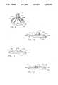
- FIG. 7is a side view of a third preferred embodiment of my multiple layer suction holder.
- FIG. 8is a cross-sectional view through the center of FIG. 7.
- FIG. 9is a perspective view of a fourth preferred embodiment of my multiple layer suction holder.
- FIG. 10is a side view of a fifth embodiment of my multiple layer suction holder.
- FIG. 11is a side view showing a sixth embodiment of my multiple layer suction holder.
- FIG. 12is a side view of a seventh embodiment of my multiple layer suction holder.
- FIG. 13is a side view of an eighth embodiment of my multiple layer suction holder.
- FIG. 14is a side view showing the multiple layer suction holder having an optional hook and spring arm.
- FIG. 15is a front view of my multiple layer suction holder having an optional spring gripping section.
- FIG. 16is a side view of the embodiment of FIG. 15.
- my suction holderincludes a lower attaching layer 2 having a convex top surface 4 and concave bottom surface 6.
- a cylindrical neck 8extends from the center of the convex top surface 4. I prefer to provide nubs or projections 10 on the neck portion 8.
- a lip 16is positioned on the circumference 3 of the lower attaching layer 2 to receive the circumference 13 of a shell 12.
- the lower attaching layer 2 and neck portion 8can be injection molded as one piece from materials having a durometer of not more than 75 such as rubber or polyvinyl chloride. However, other more soft and flexible materials having a durometer of 50 or less are desired in the instance where greater flexibility is needed to engage an unusual contoured mounting surface. Materials having a durometer of less than 50 are difficult to mold. Calendar forming which can provide a smooth finished sheet of plastic could be utilized to produce the lower attaching layer 2 having a durometer of less than 50. Once the sheet of plastic is formed by calendar forming, the lower attaching layer can be stamped therefrom.
- Softer durometer material(below 50-55) tends to fill voids in surfaces when pressed against those surfaces.
- This multi-layer suction cup with a very soft (20-50 durometer) lower layerwould form and maintain a vacuum on more porous surfaces such as some painted or enameled surfaces, as well as metal and other surfaces to which suction cups would not ordinarily stick.
- a caulk-like materialcould also be used beneath the harder, better-memory outer shell that would be formed and hold a vacuum beneath it. It could be attached to the outer shell(s) by being forced through holes or screening which would hold it in place. It could be made so that it would form a vacuum between itself, the shell above it, and the surface beneath it, and be designed so that it was self-sealing to both these surfaces.
- Iprovide a truncated shell 12 which fits on top of the lower attaching layer 2 and engages the convex top surface 4 of the lower attaching layer 2.
- the shell 12has an opening 14 through which the neck portion 8 having nubs or projections 10 extends.
- the projections 10 on the neck portion 8engage the shell 12 forcing the shell 12 against the convex top surface 4 and lip 16 thus creating pressure along the lip 16 of the lower attaching layer 2.
- This pressure along the lip 16 of the lower attaching layer 2creates increased surface contact with the mounting surface preventing air from getting under the lower attaching layer 2 and causing the suction holder from disengaging from the mounting surface.
- the positioning of the nubs or projections 10 along the neck 8dictates the amount of force applied by the shell against the lower attaching layer 2 and thus, the amount of surface contact between the lower attaching layer 2, and the mounting surface. The more surface contact, the more friction between the lower attaching layer 2 and the mounting surface, and the more weight the suction holder can support.
- the number of nubs or projections 10 located on the neck portion 8varies depending on the amount of weight that needs to be supported by the suction holder.
- the shell 12should be made of a material harder than the lower attaching layer 2 material. I prefer to use polycarbonate because of its memory, clarity and strength. Because the shell 12 and lower attaching layer 2 are made of different materials, light passing through the lower attaching layer 2 will be diffused at the interface between the lower attaching layer 2 and the shell 12. Hence, sunlight passing through a window-mounted suction holder will tend not to focus on and harm curtains, furniture or other objects located near the window.
- FIGS. 6 through 16Alternative embodiments are shown in FIGS. 6 through 16 in which like reference numerals indicate parts similar with those above described.
- Iprovide a series of annular rings 124 along the neck portion 108.
- the annular rings 124enable me to control the fit of the shell 112 against the lower attaching layer 102 by providing a means of adjustment for the shell along the neck portion 8. The further down the neck portion 108 the shell 112 is positioned, the more the shell 112 forces the lower attaching layer against the mounting surface. The more pressure the shell 112 exerts along the lip 116 of the lower attaching layer 102, the less chance of air readily passing under the lower attaching layer 102.
- threadscan also be utilized to provide a means of adjustment for the shell 112 along the neck portion 108 of the lower attaching layer 102.
- Iprovide a friction fit anchor stem 226.
- the neck 208 of the lower attaching layertakes the form of an anchor stem 226 which is friction fit within a cavity 228 located in the bottom center of the shell 212.
- the shell 212extends over the convex top surface 204 of the lower attaching layer 202 and neck 208.
- the circumference 213 of the shell 212is received by flexible lip 216 of the lower attaching layer 202.
- the shellis a truncated cone.
- This shell 312is comprised of a series of radial arms 330 which extend from the upper center portion 332 of the shell to the circumference 313 of the shell 312.
- the radial arms 330strengthen the shell 312 which increases the overall memory of the suction holder.
- the distal ends 334 of the radial arms 330engage protuberances 336 on the outer circumference of the lower attaching layer 302.
- a lower attaching layer 2 having a flexible lip 16 extending around its circumference, as shown in the embodiment of FIGS. 1 through 5,can also be utilized to engage the radial arms 330 of the shell 312.
- the shell and the lower attaching layercould also be made flat, as shown in FIGS. 10 through 13.
- the lower attaching layer 402(FIGS. 10 and 11) includes a flat circular base section 438 with tapered edge 439 and having a top surface 440 and a bottom surface 406.
- the flat base section 438further includes a neck portion 408 extending from the top surface 404 of the base section 438.
- the flat shell 412includes an opening 414 through which the neck portion 408 of the lower attaching layer 402 extends. Because both the shell 412 and the lower attaching layer 402 are flat, they share greater surface contact at their interface than the non flat embodiments of the suction holder shown in FIGS. 1 through 9. The feature of increased surface contact results in the suction holder sharing maximum surface contact with the mounting surface and being able to support greater weight.
- FIGS. 10 and 11show another embodiment of connection means for joining the lower attaching layer to the shell.
- a pin 444 or wedge 446extends transversely through an aperture or slot in the neck portion 408 and forces the shell 412 against the lower attaching layer 402.
- the degree of pressure or memory created in the lower attaching layer 402can be controlled by the amount the wedge 446 or pin 444 contacts the shell 412 and thus, forces the shell 412 against the lower attaching layer 402.
- pin or wedge connecting meanscan also be utilized with a suction holder having a non-flat lower attaching layer and non-flat shell.
- shell 512can have an elevated rim 548 along the perimeter of the shell surface which engages the lower attaching layer 502 in order to further increase memory of the suction holder.
- the circumference 513 of the shell possessing the elevated rim 548is spring loaded and engages the lower attaching layer 502 with increased pressure.
- the elevated rim 548positions the greatest amount of pressure along the circumference of the lower attaching layer 502 thus preventing any air from getting under the lower attaching layer 502 and preventing disengagement of the suction holder from the mounting surface.
- the suction holders shown in FIGS. 1 through 12have only two layers, the lower attaching layer and one shell. However, my suction holder may have more than two layers depending on the amount of weight to be supported by the suction holder. For this type of product I prefer to use one of the two types of layers shown in FIG. 13.
- multiple shells 412could be added to the lower attaching layer 502 in order to increase the surface contact between the suction holder and the mounting surface 52.
- Two shells 412extend over the neck 508 of the lower attaching portion 502 and are held against the lower attaching portions top surface 504 by projections 510. Because the shells 412 are flat, more of their surface contacts the lower attaching portion 502 top surface 504 which results in increased surface contact between the suction holder and the mounting surface 52. The more shells 412 that are employed, the greater the force that is created against the lower attaching layer 502 which results in the suction holder having maximum surface contact and maximum memory. Multiple shells having non-flat configurations, i.e. truncated cones, can also be utilized to increase the surface contact between the suction holder and the mounting surface.
- a vinyl or silicone caulk 550could be positioned adjacent the lower attaching layer 502 to create a seal between the mounting surface 52 and the lower attaching layer 502.
- the caulk 550prevents any fluids or debris from readily passing under the lower attaching layer 502 and causing the lower attaching layer to disengage from the mounting surface 52.
- a spring arm 654 acting in conjunction with a hook 622can be utilized in order to hold the sign, paper or the like and prevent the edges of the paper from curling.
- the hook 622 and spring arm 654are positioned on the shell 612. But, they may be positioned on the lower attaching layer 2.
- the paper(not shown) would extend between the spring arm 654 and the mounting surface 52.
- Ialso provide a shell 712 having a spring gripping section 756 which can be utilized to display paper 758 or the like.
- the shell having the spring gripping section 756is shown in FIGS. 15 and 16.
- the spring gripping section 756is formed by segmenting a portion of the shell 712 and positioning a lift tab 762 on the spring gripping section 756.
- the spring gripping surface 756is lifted via the lift tab 762 and the paper 758 is positioned between the spring gripping section 762 and the flat lower attaching layer 702.
- the present inventionencompasses any of the connecting means described above being utilized with any of the described shell and lower attaching layer configurations.
- the shell and lower attaching layer shown in the figureshave generally circular cross-sections, other shapes could also be used.
- Such an oblong suction cupis shown in my U.S. Pat. No. 5,078,356.
- the truncated shellcould be molded with holes in it to provide a decorative appearance.
- holescould be provided around the opening of the shell in which the holes may be shamrock or heart-shaped.
Landscapes
- Engineering & Computer Science (AREA)
- General Engineering & Computer Science (AREA)
- Mechanical Engineering (AREA)
- Hooks, Suction Cups, And Attachment By Adhesive Means (AREA)
- Supports Or Holders For Household Use (AREA)
Abstract
Description
Claims (43)
Priority Applications (1)
| Application Number | Priority Date | Filing Date | Title |
|---|---|---|---|
| US07/982,588US5318262A (en) | 1992-11-27 | 1992-11-27 | Multiple layer suction holder |
Applications Claiming Priority (1)
| Application Number | Priority Date | Filing Date | Title |
|---|---|---|---|
| US07/982,588US5318262A (en) | 1992-11-27 | 1992-11-27 | Multiple layer suction holder |
Publications (1)
| Publication Number | Publication Date |
|---|---|
| US5318262Atrue US5318262A (en) | 1994-06-07 |
Family
ID=25529321
Family Applications (1)
| Application Number | Title | Priority Date | Filing Date |
|---|---|---|---|
| US07/982,588Expired - LifetimeUS5318262A (en) | 1992-11-27 | 1992-11-27 | Multiple layer suction holder |
Country Status (1)
| Country | Link |
|---|---|
| US (1) | US5318262A (en) |
Cited By (52)
| Publication number | Priority date | Publication date | Assignee | Title |
|---|---|---|---|---|
| US5885271A (en)* | 1997-03-14 | 1999-03-23 | Millennium Cardiac Strategies, Inc. | Device for regional immobilization of a compliant body |
| US6143391A (en)* | 1998-12-11 | 2000-11-07 | Apogee Designs, Ltd. | One-piece, dual-material suction cup |
| GB2353701A (en)* | 1999-09-03 | 2001-03-07 | Proto Magic Innovations Ltd | A foot and retainer for a bath seat |
| US6316073B1 (en) | 1998-03-27 | 2001-11-13 | Anthony S. Hiscock | Multi-purpose re-usable adhesive pad |
| US6375143B1 (en)* | 1999-10-01 | 2002-04-23 | Catherine R. Burns | Releasable suction cup |
| US6405973B1 (en) | 2000-06-02 | 2002-06-18 | Kv And F Metal Products, Inc. | Disposable towel holder |
| US6422402B1 (en)* | 2001-04-23 | 2002-07-23 | E&B Giftware Llc | Napkin holder with suction cup |
| US6443388B1 (en) | 2000-06-02 | 2002-09-03 | E & B Giftware Llc | Disposable towel holder with suction cup |
| US6463598B2 (en)* | 1999-09-30 | 2002-10-15 | Victor B. David | Accessory for distributing fresh water from a faucet to bathers |
| US6553929B1 (en)* | 2000-02-02 | 2003-04-29 | Kevin Louis Harp | Hazard marker |
| US6581541B2 (en)* | 2001-05-03 | 2003-06-24 | E&B Giftware Llc | Pet bowl with suction cup |
| US20030189147A1 (en)* | 2002-04-09 | 2003-10-09 | Interdesign, Inc. | Embedded connection member |
| WO2004043244A1 (en)* | 2002-11-07 | 2004-05-27 | Ethicon, Inc. | Compliant suction surgical device |
| US20040186467A1 (en)* | 2003-03-21 | 2004-09-23 | Swanson David K. | Apparatus for maintaining contact between diagnostic and therapeutic elements and tissue and systems including the same |
| US20050070825A1 (en)* | 2001-12-06 | 2005-03-31 | Hidenori Hagiwara | Disposable weight-reducing suction cup |
| US20050119648A1 (en)* | 2003-12-02 | 2005-06-02 | Swanson David K. | Surgical methods and apparatus for stimulating tissue |
| US20050187544A1 (en)* | 2004-02-19 | 2005-08-25 | Scimed Life Systems, Inc. | Cooled probes and apparatus for maintaining contact between cooled probes and tissue |
| US20060022100A1 (en)* | 2003-10-27 | 2006-02-02 | Yung-Huei Lan | Holding device with a securing sheet for mounting onto a wall |
| US20060208142A1 (en)* | 2005-03-17 | 2006-09-21 | Adams William E Iv | Slotted suction cup with transverse bore and holding device |
| US20060271034A1 (en)* | 2005-05-28 | 2006-11-30 | Boston Scientific Scimed, Inc. | Fluid injecting devices and methods and apparatus for maintaining contact between fluid injecting devices and tissue |
| EP1847723A1 (en)* | 2006-04-20 | 2007-10-24 | Sony Corporation | Suction cup |
| US20080017768A1 (en)* | 2006-07-24 | 2008-01-24 | We-Flex, Llc | Suction-mountable display device having a periphery and a bend adjacent the periphery |
| US20080035818A1 (en)* | 2006-07-24 | 2008-02-14 | We-Flex, Llc | Portable item holder and method for using the holder |
| US20080134421A1 (en)* | 2006-12-08 | 2008-06-12 | We-Flex, Llc | Plunger device |
| US20090032663A1 (en)* | 2007-05-29 | 2009-02-05 | Eagle Fan | Sucker Assembly |
| US20090224117A1 (en)* | 2008-03-07 | 2009-09-10 | Sony Corporation | Suction cup device and article attaching apparatus |
| US7608072B2 (en) | 2003-12-02 | 2009-10-27 | Boston Scientific Scimed, Inc. | Surgical methods and apparatus for maintaining contact between tissue and electrophysiology elements and confirming whether a therapeutic lesion has been formed |
| GB2463325A (en)* | 2008-09-16 | 2010-03-17 | Proto Magic Innovations Ltd | Suction cup retention means |
| US20100096513A1 (en)* | 2008-10-22 | 2010-04-22 | Frank Denis Beebe | Pool vacuum hose clip/ lane buoy clip |
| USD659519S1 (en)* | 2010-12-09 | 2012-05-15 | Trimtag Trading Inc. | Hanger |
| USD664422S1 (en)* | 2011-08-18 | 2012-07-31 | Jiin Haur Industrial Co., Ltd. | Suction-type bracket |
| CN103115063A (en)* | 2013-02-07 | 2013-05-22 | 中山市太力家庭用品制造有限公司 | Sucker |
| US20140094724A1 (en)* | 2012-09-28 | 2014-04-03 | Zoll Medical Corporation | Method and Device for Performing Alternating Chest Compression and Decompression |
| CN104842868A (en)* | 2015-03-20 | 2015-08-19 | 盐城工学院 | Automobile trunk with lamp |
| US20160309938A1 (en)* | 2015-04-24 | 2016-10-27 | Jamie Ortiz | Rotary organizer for brushes |
| US20180343826A1 (en)* | 2017-06-05 | 2018-12-06 | Sudhir Kumar | Feeding Bowl Securement Apparatus |
| US20180355906A1 (en)* | 2014-03-07 | 2018-12-13 | Isee Store Innovations, L.L.C. | Securing assembly |
| US20190021519A1 (en)* | 2014-03-07 | 2019-01-24 | Isee Store Innovations, L.L.C. | Securing assemblies for systems and methods for securing and displaying products |
| US20190290022A1 (en)* | 2018-03-21 | 2019-09-26 | K-International, Inc. | Advertising panel and method for mounting to a surface |
| US10568465B2 (en) | 2017-05-11 | 2020-02-25 | Summer Infant (usa) Inc. | Bath seat |
| US20200093285A1 (en)* | 2018-09-21 | 2020-03-26 | Isee Store Innovations, L.L.C. | Product displaying holder systems |
| US10610062B2 (en)* | 2018-08-31 | 2020-04-07 | Jeffery Alan Mieldon | Washcloth identification system |
| EP1745217B2 (en)† | 2004-05-03 | 2020-04-15 | Schmidt, Patrick | Suction-type holding device |
| US10639234B2 (en) | 2015-10-16 | 2020-05-05 | Zoll Circulation, Inc. | Automated chest compression device |
| US10682282B2 (en) | 2015-10-16 | 2020-06-16 | Zoll Circulation, Inc. | Automated chest compression device |
| US10874583B2 (en) | 2017-04-20 | 2020-12-29 | Zoll Circulation, Inc. | Compression belt assembly for a chest compression device |
| US10905629B2 (en) | 2018-03-30 | 2021-02-02 | Zoll Circulation, Inc. | CPR compression device with cooling system and battery removal detection |
| US11022168B1 (en) | 2020-05-01 | 2021-06-01 | Isee Store Innovations, L.L.C. | Securing assembly having container retaining housing |
| US11246795B2 (en) | 2017-04-20 | 2022-02-15 | Zoll Circulation, Inc. | Compression belt assembly for a chest compression device |
| US11280367B2 (en) | 2020-04-29 | 2022-03-22 | Isee Store Innovations, L.L.C. | Securing assembly having component support hook |
| USD972639S1 (en)* | 2019-09-13 | 2022-12-13 | SpinTopSigns, LLC | Display sign |
| US11673711B2 (en) | 2020-08-03 | 2023-06-13 | Isee Store Innovations, L.L.C. | Fluid container retaining systems and methods |
Citations (6)
| Publication number | Priority date | Publication date | Assignee | Title |
|---|---|---|---|---|
| US3310267A (en)* | 1966-08-01 | 1967-03-21 | Koehler Sandra Sue | Wig support |
| US3750991A (en)* | 1971-05-05 | 1973-08-07 | M Ragir | Suction mounting device |
| US4813640A (en)* | 1986-10-24 | 1989-03-21 | Easy Italy S.D.F. Di Perentin Alessandro & C. | Suction-cup with a pin put in, fitted to prop up some points of support for clothes on transparent or not transparent panels, particularly suitable to prepare shop-windows, shows, etc. |
| US5029786A (en)* | 1990-05-21 | 1991-07-09 | Hans Wu | Suction cup |
| US5104077A (en)* | 1990-09-07 | 1992-04-14 | Hung Mei Brush Co., Ltd. | Suction cup |
| US5176346A (en)* | 1991-02-11 | 1993-01-05 | Liu Bao Shen | Suction cup device |
- 1992
- 1992-11-27USUS07/982,588patent/US5318262A/ennot_activeExpired - Lifetime
Patent Citations (6)
| Publication number | Priority date | Publication date | Assignee | Title |
|---|---|---|---|---|
| US3310267A (en)* | 1966-08-01 | 1967-03-21 | Koehler Sandra Sue | Wig support |
| US3750991A (en)* | 1971-05-05 | 1973-08-07 | M Ragir | Suction mounting device |
| US4813640A (en)* | 1986-10-24 | 1989-03-21 | Easy Italy S.D.F. Di Perentin Alessandro & C. | Suction-cup with a pin put in, fitted to prop up some points of support for clothes on transparent or not transparent panels, particularly suitable to prepare shop-windows, shows, etc. |
| US5029786A (en)* | 1990-05-21 | 1991-07-09 | Hans Wu | Suction cup |
| US5104077A (en)* | 1990-09-07 | 1992-04-14 | Hung Mei Brush Co., Ltd. | Suction cup |
| US5176346A (en)* | 1991-02-11 | 1993-01-05 | Liu Bao Shen | Suction cup device |
Cited By (82)
| Publication number | Priority date | Publication date | Assignee | Title |
|---|---|---|---|---|
| US6159201A (en)* | 1997-03-14 | 2000-12-12 | Millennium Cardiac Strategies, Inc. | Device for regional immobilization of a compliant body |
| US5885271A (en)* | 1997-03-14 | 1999-03-23 | Millennium Cardiac Strategies, Inc. | Device for regional immobilization of a compliant body |
| US6316073B1 (en) | 1998-03-27 | 2001-11-13 | Anthony S. Hiscock | Multi-purpose re-usable adhesive pad |
| US6143391A (en)* | 1998-12-11 | 2000-11-07 | Apogee Designs, Ltd. | One-piece, dual-material suction cup |
| GB2353701A (en)* | 1999-09-03 | 2001-03-07 | Proto Magic Innovations Ltd | A foot and retainer for a bath seat |
| GB2353701B (en)* | 1999-09-03 | 2001-08-08 | Proto Magic Innovations Ltd | A foot for a bath seat |
| US6463598B2 (en)* | 1999-09-30 | 2002-10-15 | Victor B. David | Accessory for distributing fresh water from a faucet to bathers |
| US6375143B1 (en)* | 1999-10-01 | 2002-04-23 | Catherine R. Burns | Releasable suction cup |
| US6553929B1 (en)* | 2000-02-02 | 2003-04-29 | Kevin Louis Harp | Hazard marker |
| US6443388B1 (en) | 2000-06-02 | 2002-09-03 | E & B Giftware Llc | Disposable towel holder with suction cup |
| US6405973B1 (en) | 2000-06-02 | 2002-06-18 | Kv And F Metal Products, Inc. | Disposable towel holder |
| US9345347B2 (en)* | 2000-09-13 | 2016-05-24 | Yung-Huei Lan | Holding device with a securing sheet for mounting onto a wall |
| US20100038502A1 (en)* | 2000-09-13 | 2010-02-18 | Yung-Huei Lan | Holding device with a securing sheet for mounting onto a wall |
| US6422402B1 (en)* | 2001-04-23 | 2002-07-23 | E&B Giftware Llc | Napkin holder with suction cup |
| US6581541B2 (en)* | 2001-05-03 | 2003-06-24 | E&B Giftware Llc | Pet bowl with suction cup |
| US20050070825A1 (en)* | 2001-12-06 | 2005-03-31 | Hidenori Hagiwara | Disposable weight-reducing suction cup |
| US20030189147A1 (en)* | 2002-04-09 | 2003-10-09 | Interdesign, Inc. | Embedded connection member |
| US6749165B2 (en)* | 2002-04-09 | 2004-06-15 | Interdesign, Inc. | Holder assembly having an embedded hook and securing member |
| WO2004043244A1 (en)* | 2002-11-07 | 2004-05-27 | Ethicon, Inc. | Compliant suction surgical device |
| US20040186467A1 (en)* | 2003-03-21 | 2004-09-23 | Swanson David K. | Apparatus for maintaining contact between diagnostic and therapeutic elements and tissue and systems including the same |
| US20060022100A1 (en)* | 2003-10-27 | 2006-02-02 | Yung-Huei Lan | Holding device with a securing sheet for mounting onto a wall |
| US7575208B2 (en)* | 2003-10-27 | 2009-08-18 | Yung-Huei Lan | Holding device with a securing sheet for mounting onto a wall |
| US20050119648A1 (en)* | 2003-12-02 | 2005-06-02 | Swanson David K. | Surgical methods and apparatus for stimulating tissue |
| US8052676B2 (en) | 2003-12-02 | 2011-11-08 | Boston Scientific Scimed, Inc. | Surgical methods and apparatus for stimulating tissue |
| US7608072B2 (en) | 2003-12-02 | 2009-10-27 | Boston Scientific Scimed, Inc. | Surgical methods and apparatus for maintaining contact between tissue and electrophysiology elements and confirming whether a therapeutic lesion has been formed |
| US20050187544A1 (en)* | 2004-02-19 | 2005-08-25 | Scimed Life Systems, Inc. | Cooled probes and apparatus for maintaining contact between cooled probes and tissue |
| US7371233B2 (en) | 2004-02-19 | 2008-05-13 | Boston Scientific Scimed, Inc. | Cooled probes and apparatus for maintaining contact between cooled probes and tissue |
| EP1745217B2 (en)† | 2004-05-03 | 2020-04-15 | Schmidt, Patrick | Suction-type holding device |
| US20060208142A1 (en)* | 2005-03-17 | 2006-09-21 | Adams William E Iv | Slotted suction cup with transverse bore and holding device |
| US8480045B2 (en)* | 2005-03-17 | 2013-07-09 | Adams Mfg. Corp. | Slotted suction cup with transverse bore and holding device |
| US8016822B2 (en) | 2005-05-28 | 2011-09-13 | Boston Scientific Scimed, Inc. | Fluid injecting devices and methods and apparatus for maintaining contact between fluid injecting devices and tissue |
| US20060271034A1 (en)* | 2005-05-28 | 2006-11-30 | Boston Scientific Scimed, Inc. | Fluid injecting devices and methods and apparatus for maintaining contact between fluid injecting devices and tissue |
| US7690609B2 (en) | 2006-04-20 | 2010-04-06 | Sony Corporation | Suction cup |
| EP1847723A1 (en)* | 2006-04-20 | 2007-10-24 | Sony Corporation | Suction cup |
| CN100585197C (en)* | 2006-04-20 | 2010-01-27 | 索尼株式会社 | Suction cup |
| US20070246621A1 (en)* | 2006-04-20 | 2007-10-25 | Sony Corporation | Suction cup |
| US20080017768A1 (en)* | 2006-07-24 | 2008-01-24 | We-Flex, Llc | Suction-mountable display device having a periphery and a bend adjacent the periphery |
| US7740221B2 (en) | 2006-07-24 | 2010-06-22 | Sheffield Jr Douglas M | Suction-mountable display device having a periphery and a bend adjacent the periphery |
| US20080035818A1 (en)* | 2006-07-24 | 2008-02-14 | We-Flex, Llc | Portable item holder and method for using the holder |
| US20080134421A1 (en)* | 2006-12-08 | 2008-06-12 | We-Flex, Llc | Plunger device |
| US20090032663A1 (en)* | 2007-05-29 | 2009-02-05 | Eagle Fan | Sucker Assembly |
| US20090224117A1 (en)* | 2008-03-07 | 2009-09-10 | Sony Corporation | Suction cup device and article attaching apparatus |
| GB2463325B (en)* | 2008-09-16 | 2010-08-11 | Proto Magic Innovations Ltd | Sucker retention means |
| GB2463325A (en)* | 2008-09-16 | 2010-03-17 | Proto Magic Innovations Ltd | Suction cup retention means |
| US20100096513A1 (en)* | 2008-10-22 | 2010-04-22 | Frank Denis Beebe | Pool vacuum hose clip/ lane buoy clip |
| USD659519S1 (en)* | 2010-12-09 | 2012-05-15 | Trimtag Trading Inc. | Hanger |
| USD664422S1 (en)* | 2011-08-18 | 2012-07-31 | Jiin Haur Industrial Co., Ltd. | Suction-type bracket |
| US9655809B2 (en)* | 2012-09-28 | 2017-05-23 | Zoll Medical Corporation | Method and device for performing alternating chest compression and decompression |
| US20150105705A1 (en)* | 2012-09-28 | 2015-04-16 | Zoll Medical Corporation | Method and Device for Performing Alternating Chest Compression and Decompression |
| CN104755058A (en)* | 2012-09-28 | 2015-07-01 | 佐尔医药公司 | Method and device for performing alternating chest compression and decompression |
| US8920348B2 (en)* | 2012-09-28 | 2014-12-30 | Zoll Medical Corporation | Method and device for performing alternating chest compression and decompression |
| US20140094724A1 (en)* | 2012-09-28 | 2014-04-03 | Zoll Medical Corporation | Method and Device for Performing Alternating Chest Compression and Decompression |
| CN103115063A (en)* | 2013-02-07 | 2013-05-22 | 中山市太力家庭用品制造有限公司 | Sucker |
| US20190021519A1 (en)* | 2014-03-07 | 2019-01-24 | Isee Store Innovations, L.L.C. | Securing assemblies for systems and methods for securing and displaying products |
| US20180355906A1 (en)* | 2014-03-07 | 2018-12-13 | Isee Store Innovations, L.L.C. | Securing assembly |
| US10393168B2 (en)* | 2014-03-07 | 2019-08-27 | Isee Store Innovations, Llc | Securing assembly |
| US10588406B2 (en)* | 2014-03-07 | 2020-03-17 | Isee Store Innovations, L.L.C. | Securing assemblies for systems and methods for securing and displaying products |
| CN104842868A (en)* | 2015-03-20 | 2015-08-19 | 盐城工学院 | Automobile trunk with lamp |
| US20160309938A1 (en)* | 2015-04-24 | 2016-10-27 | Jamie Ortiz | Rotary organizer for brushes |
| US10863842B2 (en)* | 2015-04-24 | 2020-12-15 | Jamie Ortiz | Rotary organizer for brushes |
| US11723833B2 (en) | 2015-10-16 | 2023-08-15 | Zoll Circulation, Inc. | Automated chest compression device |
| US11666506B2 (en) | 2015-10-16 | 2023-06-06 | Zoll Circulation, Inc. | Automated chest compression device |
| US10682282B2 (en) | 2015-10-16 | 2020-06-16 | Zoll Circulation, Inc. | Automated chest compression device |
| US10639234B2 (en) | 2015-10-16 | 2020-05-05 | Zoll Circulation, Inc. | Automated chest compression device |
| US10874583B2 (en) | 2017-04-20 | 2020-12-29 | Zoll Circulation, Inc. | Compression belt assembly for a chest compression device |
| US11246795B2 (en) | 2017-04-20 | 2022-02-15 | Zoll Circulation, Inc. | Compression belt assembly for a chest compression device |
| US12193990B2 (en) | 2017-04-20 | 2025-01-14 | Zoll Circulation, Inc. | Compression belt assembly for a chest compression device |
| US11813224B2 (en) | 2017-04-20 | 2023-11-14 | Zoll Circulation, Inc. | Compression belt assembly for a chest compression device |
| US10568465B2 (en) | 2017-05-11 | 2020-02-25 | Summer Infant (usa) Inc. | Bath seat |
| US11197587B2 (en) | 2017-05-11 | 2021-12-14 | Summer Infant (Usa), Inc. | Bath seat |
| US20180343826A1 (en)* | 2017-06-05 | 2018-12-06 | Sudhir Kumar | Feeding Bowl Securement Apparatus |
| US20190290022A1 (en)* | 2018-03-21 | 2019-09-26 | K-International, Inc. | Advertising panel and method for mounting to a surface |
| US10477987B2 (en)* | 2018-03-21 | 2019-11-19 | K-International, Inc. | Advertising panel and method for mounting to a surface |
| US10905629B2 (en) | 2018-03-30 | 2021-02-02 | Zoll Circulation, Inc. | CPR compression device with cooling system and battery removal detection |
| US12144778B2 (en) | 2018-03-30 | 2024-11-19 | Zoll Circulation, Inc. | CPR compression device with cooling system and battery removal detection |
| US10610062B2 (en)* | 2018-08-31 | 2020-04-07 | Jeffery Alan Mieldon | Washcloth identification system |
| US10912401B2 (en)* | 2018-09-21 | 2021-02-09 | Isee Store Innovations, L.L.C. | Product displaying holder systems |
| US20200093285A1 (en)* | 2018-09-21 | 2020-03-26 | Isee Store Innovations, L.L.C. | Product displaying holder systems |
| USD972639S1 (en)* | 2019-09-13 | 2022-12-13 | SpinTopSigns, LLC | Display sign |
| US11280367B2 (en) | 2020-04-29 | 2022-03-22 | Isee Store Innovations, L.L.C. | Securing assembly having component support hook |
| US11022168B1 (en) | 2020-05-01 | 2021-06-01 | Isee Store Innovations, L.L.C. | Securing assembly having container retaining housing |
| US11673711B2 (en) | 2020-08-03 | 2023-06-13 | Isee Store Innovations, L.L.C. | Fluid container retaining systems and methods |
Similar Documents
| Publication | Publication Date | Title |
|---|---|---|
| US5318262A (en) | Multiple layer suction holder | |
| US5769144A (en) | Eyelet reinforcement for curtains | |
| CA3085023C (en) | Hook and lattice adjustable wreath hanger | |
| US5709462A (en) | Mounting for conventional decorative light strings | |
| RU2637973C1 (en) | Vacuum suction cup | |
| US20230228290A1 (en) | Universal quick-release vacuum connector | |
| US4561200A (en) | Display device | |
| CA2112346A1 (en) | Airspring piston and airspring assembly | |
| US5402974A (en) | Self-closing holder | |
| GB2124294A (en) | Hinge for toilet seat | |
| CA2103153A1 (en) | Suction-type clamp | |
| EP0287059B1 (en) | Ornamental button | |
| EP0001916A1 (en) | A reusable badge and a press for making the same | |
| US5195220A (en) | Decorative and aesthetic multi-part buckle for belts and the like and the fabrication thereof | |
| US2806314A (en) | Christmas decoration | |
| US9435371B2 (en) | Varied diameter suction cup | |
| US4796329A (en) | Faucet handle | |
| US4446642A (en) | Peripheral decorative article | |
| EP0580343A1 (en) | Cord stopper | |
| US2619640A (en) | Combination cap and eyeshield | |
| US20190159615A1 (en) | Spill-proof lid for drinking vessel | |
| US4549331A (en) | Button for receiving and securing a fabric covering therefor and fabric-covered button assembly formed therewith | |
| US8769849B1 (en) | Device for table settings | |
| US4761863A (en) | Structure of snap | |
| US4158251A (en) | Button construction for tufted boat upholstery |
Legal Events
| Date | Code | Title | Description |
|---|---|---|---|
| AS | Assignment | Owner name:ADAMS MFG. CORP., PENNSYLVANIA Free format text:ASSIGNMENT OF ASSIGNORS INTEREST.;ASSIGNOR:ADAMS, WILLIAM E.;REEL/FRAME:006359/0952 Effective date:19921123 | |
| STCF | Information on status: patent grant | Free format text:PATENTED CASE | |
| CC | Certificate of correction | ||
| FEPP | Fee payment procedure | Free format text:PAYOR NUMBER ASSIGNED (ORIGINAL EVENT CODE: ASPN); ENTITY STATUS OF PATENT OWNER: SMALL ENTITY | |
| FPAY | Fee payment | Year of fee payment:4 | |
| FPAY | Fee payment | Year of fee payment:8 | |
| REMI | Maintenance fee reminder mailed | ||
| FPAY | Fee payment | Year of fee payment:12 | |
| AS | Assignment | Owner name:UBS AG, LONDON BRANCH, AS AGENT, GREAT BRITAIN Free format text:SECURITY INTEREST;ASSIGNOR:ADAMS MFG. CORP.;REEL/FRAME:047975/0860 Effective date:20181221 | |
| AS | Assignment | Owner name:ADAMS MFG. CORP., PENNSYLVANIA Free format text:RELEASE BY SECURED PARTY;ASSIGNOR:UBS AG, LONDON BRANCH, IN ITS CAPACITY AS SECURITY AGENT FOR THE SECURED PARTIES;REEL/FRAME:071236/0860 Effective date:20250403 |