US5317441A - Transceiver for full duplex signalling on a fiber optic cable - Google Patents
Transceiver for full duplex signalling on a fiber optic cableDownload PDFInfo
- Publication number
- US5317441A US5317441AUS07/779,829US77982991AUS5317441AUS 5317441 AUS5317441 AUS 5317441AUS 77982991 AUS77982991 AUS 77982991AUS 5317441 AUS5317441 AUS 5317441A
- Authority
- US
- United States
- Prior art keywords
- signal
- transceiver
- optical signal
- component
- output signal
- Prior art date
- Legal status (The legal status is an assumption and is not a legal conclusion. Google has not performed a legal analysis and makes no representation as to the accuracy of the status listed.)
- Expired - Lifetime
Links
Images

Classifications
- H—ELECTRICITY
- H04—ELECTRIC COMMUNICATION TECHNIQUE
- H04B—TRANSMISSION
- H04B10/00—Transmission systems employing electromagnetic waves other than radio-waves, e.g. infrared, visible or ultraviolet light, or employing corpuscular radiation, e.g. quantum communication
- H04B10/40—Transceivers
Definitions
- the present inventionrelates to fiber optic transmission systems in general and in particular to a transceiver for providing full duplex signalling in an optical transmission system comprising a single fiber optic cable.
- a full duplex communication transmission systemin general comprises one or more transmission line(s) having both a receiver and a transmitter, i.e. transceiver, located at each end of the line(s) for simultaneously receiving and transmitting signals.
- a transmitteri.e. transceiver
- principal objects of the present inventionare a method and apparatus for providing full duplex signal transmissions over a single fiber optic cable.
- a transceivercomprising means for separating a transmitted signal from a received signal at both ends of the fiber optic cable.
- the separating meanscomprises a laser transmitter having or used with a back-facet sensing diode.
- the output from the back-facet sensing diodeis applied to one input of a differential amplifier and compared with the electrical signal used to drive the laser transmitter.
- Delay and amplitude compensating meansis provided to equalize the output of the back-facet sensing diode and the electrical signal used to drive the laser transmitter so as to null the output of the differential amplifier.
- an optical output from the fiber optic cable which is received from a distant transmitter and sensed by the back-facet sensing diodeis not nulled out locally, and so appears on the output of the differential amplifier as a received signal.
- a beam splitter and a light sensing diode or the likeis used at each end of the cable in place of the back-facet sensing diode for transducing a portion of the transmitted optical signal for application to one input of a differential amplifier or other comparator.
- the transmitted signalsmay be either digital or analog.
- the only significant signal limitationbeing that the total optical signal, i.e. the sum of the transmitted and received signals, must be within the dynamic range of the receiving electronics. Accordingly, the maximum transmitted power in a full duplex signal fiber optic system is limited to about one half of the power that can be transmitted in a half-duplex system using the same electronics.
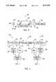
- FIG. 1is a schematic diagram of a prior art electrical, hybrid full duplex signalling system
- FIG. 2is a schematic diagram of an embodiment of the present invention
- FIG. 3is a perspective diagrammatic view of a source of current radiation with a back-facet sensing diode is used in the embodiment of FIG. 2;
- FIG. 4is another embodiment of the present invention.
- a standard electrical hybrid duplex signal communication systemdesignated generally as 1, comprising a local transceiver 2 and a substantially identical remote transceiver 3 which are interconnected by means of a coaxial cable 4 having a line impedance Z 0 .
- the terms local and remoteare used simply to indicate that the remote transceiver 3 is located at a distance from the local transceiver 2.
- a driver 5 and a termination 7are provided in each of the transceivers 2 and 3 in each of the transceivers 2 and 3 in each of the transceivers 2 and 3 in each of the transceivers 2 and 3 in each of the transceivers 2 and 3 there is provided a driver 5 and a termination 7.
- the driver 5has a single-ended output line 8 (a single line which is referenced to a local ground 9) for providing an output which is applied equally via two-resistor voltage divider networks 10 and 11 to the true and complementary or inverting inputs of a differential amplifier 12 which is the front end of a receiver 13.
- the resistor voltage divider networks 10 and 11each comprise a pair of resistors R.
- the termination 7comprises a resistance Z 0 corresponding to the impedance Z 0 of the coaxial cable 4 so as to balance the networks 10 and 11.
- the signal from the driver 5is applied as a common mode voltage to the differential amplifier 12 of the receiver 13, the voltage difference which the differential amplifier 12 sees is zero and the receiver 12 does not respond to the output of the local driver 5.
- an electrical signal applied to the driver 5 by means of an input line 14is amplified by the local driver 5 and is propagated down the coaxial cable 4 to the remote transceiver 3.
- the signal received from the transceiver 2unbalances the voltages developed across voltage divider networks 10 and 11 located therein and produces a differential input in the differential amplifier 12 in the transceiver 3.
- the output from the amplifier 12 in the transceiver 3comprises a faithful reproduction of the signal from the driver 5 in the transceiver 2.
- a signal originating from the driver 5 in the transceiver 3unbalances the voltages across the voltage drivers 10 and 11 in the transceiver 2, developing a differential signal at the input of the amplifier 12 which is faithfully reproduced at the output of the amplifier 12.
- simultaneously sending and receiving signals over a single conductor (plus return)is achieved by actively cancelling out the effect of the driver 5 on their associated receivers 13.
- a full duplex optical transmission system designated generally as 30comprising a local transceiver 31 and a substantially identical remote transceiver 32 which are interconnected by a single fiber optic cable 40.
- a driver 33In each of the transceivers 31 and 32 there is provided a driver 33, an optical receiver-transmitter circuit 34, a receiver amplifier 35, a delay and compensation circuit 36, and a differential amplifier 37.
- a source of optical radiationsuch as a forward biased transmitting laser diode 38, and an optical signal receiver, such as a reverse bias back-facet sensing diode 39.
- the transmitting diodewill be driven by a current source whose path is through the diode to ground.
- a current sourcewhose path is through the diode to ground.
- the cathode of the receiving diodes 39which are reverse biased, is typically connected to the supply rail.
- the source of optical radiationtypically comprises a laser diode 50 having a front facet 51 and a rear facet 52.
- an electrical signal applied to the input of the driver 33drives the diode 50.
- Radiation from the diode 50, as represented by the arrow 53,is then projected through a lens 54 for propagation on the fiber optic cable 40 to the transceiver 32.
- Optical signals received from the transceiver 32 via the fiber optic cable 40exit the back facet of the diode 50 as shown by the arrow 55 and are detected by the back-facet sensing diode 39.
- the electrical signal which is applied to the input of the driver 33is also applied to the input of the delay and compensation circuit 36.
- the output of the delay and compensation circuit 36drives one input of the differential amplifier 37.
- the other input of the differential amplifier 37is driven by an amplified version of the signal developed by the receiver diode 39 which comprises a first component corresponding to the optical output of the source 38 and a second component which corresponds to the optical signal from the fiber optic cable 40 which is transmitted by the remote transceiver 32.
- optical signals generated in the transceiver 32 for transmission to the local transceiver 31are separated from signals received by the transceiver 32 from the transceiver 31 in the same manner, thus providing full duplex operation in an optical system using a single fiber optic cable.
- a full duplex signalling transmission systemdesignated generally as 60.
- a local transceiver 61 and a remote transceiver 62In each of the transceivers 61 and 62 there is provided a source of coherent radiation 63, such as a laser diode, a delay and compensation circuit 64, a receiver 65, a comparator 66 and a beam splitter 67.
- the optical transceiver 61 and 62are interconnected by a fiber optic cable 68.
- an electrical signal applied to the input of the transmitter 63 on an input line 69results in the generation of an optical signal represented by the arrow 70.
- a portion of the optical signal 70is directed through the fiber optic cable 68 to the transceiver 62 as shown by the arrow 71 and to the receiver 65 as shown by the arrow 72.
- the electrical signal applied to the transmitter 63is also applied to the input of the delay and compensation circuit 64.
- the output of the receiver 65 due to radiation directed thereto by the beam splitter 67comprises a first component corresponding to the optical signal transmitted to the transceiver 62 and a second component corresponding to the optical signal received from the fiber optic cable 68.
- the delay and compensation circuit 64provides an output which corresponds to the magnitude and phase of the first component of the output of the receiver 65, namely the optical signal transmitted to the transceiver 62.
- the comparator 66the outputs of the delay and compensation circuit 64 and the receiver 65 are compared as in a differential amplifier described above with respect to FIG. 2.
- the transceiver 62Since the effects of the optical signal transmitted from the transceiver 61 to the transceiver 62 are cancelled by the differential amplifier in the comparator 66.
- the output of the comparator 66is a faithful reproduction of the optical signal received from the transceiver 62.
- the transceiver 62operates in substantially the same manner as described above with respect to the transceiver 61.
- edge emitting LED driverscan be modified to have the equivalent of the laser diodes back-facet sensing diode.
- delay and compensation circuits 36 and 64 described abovecomprise basically a voltage divider possibly buffered by an amplifier and an adjustable delay element such as a tapped delay line, or in the case of digital signals a string of logic gates, other types of delay and compensation circuits may also be used.
- the principles of the present invention as described aboveare applicable to both analog as well as digital optical signals and that the invention may be used in conjunction with the above-described prior known full duplex signalling schemes to permit even more channels to share a single fiber.
Landscapes
- Physics & Mathematics (AREA)
- Electromagnetism (AREA)
- Engineering & Computer Science (AREA)
- Computer Networks & Wireless Communication (AREA)
- Signal Processing (AREA)
- Optical Communication System (AREA)
Abstract
Description
Claims (14)
Priority Applications (1)
| Application Number | Priority Date | Filing Date | Title |
|---|---|---|---|
| US07/779,829US5317441A (en) | 1991-10-21 | 1991-10-21 | Transceiver for full duplex signalling on a fiber optic cable |
Applications Claiming Priority (1)
| Application Number | Priority Date | Filing Date | Title |
|---|---|---|---|
| US07/779,829US5317441A (en) | 1991-10-21 | 1991-10-21 | Transceiver for full duplex signalling on a fiber optic cable |
Publications (1)
| Publication Number | Publication Date |
|---|---|
| US5317441Atrue US5317441A (en) | 1994-05-31 |
Family
ID=25117702
Family Applications (1)
| Application Number | Title | Priority Date | Filing Date |
|---|---|---|---|
| US07/779,829Expired - LifetimeUS5317441A (en) | 1991-10-21 | 1991-10-21 | Transceiver for full duplex signalling on a fiber optic cable |
Country Status (1)
| Country | Link |
|---|---|
| US (1) | US5317441A (en) |
Cited By (64)
| Publication number | Priority date | Publication date | Assignee | Title |
|---|---|---|---|---|
| US5448390A (en)* | 1993-01-14 | 1995-09-05 | Nippon Telegraph And Telephone Corporation | Wavelength division multiplex bothway optical communication system |
| US5500755A (en)* | 1993-04-27 | 1996-03-19 | Alcatel Sel Aktiengesellschaft | Compensation device |
| US5677779A (en)* | 1994-07-01 | 1997-10-14 | Fujitsu Limited | Optical communications module |
| US5956169A (en)* | 1995-07-06 | 1999-09-21 | Fujitsu Limited | Bidirectional optical burst transmission |
| EP1058457A1 (en)* | 1999-06-02 | 2000-12-06 | Sony Corporation | An optical connection part of an optical fiber cable, and an optical communication apparatus using the same |
| US6407846B1 (en) | 2001-03-16 | 2002-06-18 | All Optical Networks, Inc. | Photonic wavelength shifting method |
| US6434363B2 (en)* | 1996-12-30 | 2002-08-13 | Nokia Mobile Phones Limited | Infrared link |
| US20020131100A1 (en)* | 2001-03-16 | 2002-09-19 | Myers Michael H. | Method for photonic wavelength error detection |
| US20020131125A1 (en)* | 2001-03-16 | 2002-09-19 | Myers Michael H. | Replicated-spectrum photonic transceiving |
| US20030053178A1 (en)* | 2001-08-28 | 2003-03-20 | Karlquist Richard K. | Frequency translating devices and frequency translating measurement systems that utilize light-activated resistors |
| US6597479B1 (en) | 1999-10-22 | 2003-07-22 | Adtran, Inc. | Fiber quadrupler device method for providing full duplex communications to a synchronous optical network over a single optical fiber |
| US20030189975A1 (en)* | 1994-09-20 | 2003-10-09 | Fullerton Larry W. | Method and transceiver for full duplex communication of ultra wideband signals |
| US20040076193A1 (en)* | 2000-02-03 | 2004-04-22 | Daisuke Nakano | Apparatus and method for data communication |
| US6731881B2 (en)* | 1999-12-01 | 2004-05-04 | Nec Corporation | Device for transmitting and receiving optical signals |
| WO2005013517A3 (en)* | 2003-07-30 | 2005-04-28 | Denselight Semiconductors Pte | Optical transceiver with reduced optical cross-talk between transmitter and receiver |
| US20050095994A1 (en)* | 2003-10-29 | 2005-05-05 | Infineon Technologies Ag | Transmitting and receiving device |
| US20060210280A1 (en)* | 2005-03-08 | 2006-09-21 | Shigeo Hayashi | Optical transceiver |
| US20070147844A1 (en)* | 2005-12-23 | 2007-06-28 | The Boeing Company | Bi-directional, full-duplex, one-wire communications link for use in fiber optic transceivers |
| US20070223919A1 (en)* | 2006-03-27 | 2007-09-27 | Fujitsu Limited | Optical apparatus |
| US20080189444A1 (en)* | 2007-02-07 | 2008-08-07 | Honeywell International Inc. | System of circumvention and recovery in a multi-function system |
| US20080189449A1 (en)* | 2007-02-07 | 2008-08-07 | Honeywell International Inc. | Method of peripheral type identification in a system of circumvention and recovery |
| US20080189448A1 (en)* | 2007-02-07 | 2008-08-07 | Honeywell International Inc. | Method for implementing a control channel in a system of circumvention and recovery |
| US20080256375A1 (en)* | 2007-04-12 | 2008-10-16 | Honeywell International Inc. | System of integrated environmenatlly hardened architecture for space application |
| US7539237B2 (en) | 1996-12-06 | 2009-05-26 | Alereon, Inc. | Fast locking mechanism for channelized ultrawide-band communications |
| US20100061734A1 (en)* | 2008-09-05 | 2010-03-11 | Knapp David J | Optical communication device, method and system |
| US20100327764A1 (en)* | 2008-09-05 | 2010-12-30 | Knapp David J | Intelligent illumination device |
| US20110063214A1 (en)* | 2008-09-05 | 2011-03-17 | Knapp David J | Display and optical pointer systems and related methods |
| US20110063268A1 (en)* | 2008-09-05 | 2011-03-17 | Knapp David J | Display calibration systems and related methods |
| US20110069960A1 (en)* | 2008-09-05 | 2011-03-24 | Knapp David J | Systems and methods for visible light communication |
| US20110069094A1 (en)* | 2008-09-05 | 2011-03-24 | Knapp David J | Illumination devices and related systems and methods |
| USRE42814E1 (en) | 1998-10-30 | 2011-10-04 | Acqis Technology, Inc. | Password protected modular computer method and device |
| US20110253915A1 (en)* | 2008-09-05 | 2011-10-20 | Knapp David J | Led transceiver front end circuitry and related methods |
| USRE42984E1 (en) | 1999-05-14 | 2011-11-29 | Acqis Technology, Inc. | Data security method and device for computer modules |
| US20130294294A1 (en)* | 2012-05-07 | 2013-11-07 | Broadcom Corporation | Power-efficient driver architecture |
| US8749172B2 (en) | 2011-07-08 | 2014-06-10 | Ketra, Inc. | Luminance control for illumination devices |
| US9146028B2 (en) | 2013-12-05 | 2015-09-29 | Ketra, Inc. | Linear LED illumination device with improved rotational hinge |
| US9155155B1 (en) | 2013-08-20 | 2015-10-06 | Ketra, Inc. | Overlapping measurement sequences for interference-resistant compensation in light emitting diode devices |
| US9237620B1 (en) | 2013-08-20 | 2016-01-12 | Ketra, Inc. | Illumination device and temperature compensation method |
| US9237623B1 (en) | 2015-01-26 | 2016-01-12 | Ketra, Inc. | Illumination device and method for determining a maximum lumens that can be safely produced by the illumination device to achieve a target chromaticity |
| US9237612B1 (en) | 2015-01-26 | 2016-01-12 | Ketra, Inc. | Illumination device and method for determining a target lumens that can be safely produced by an illumination device at a present temperature |
| US9247605B1 (en) | 2013-08-20 | 2016-01-26 | Ketra, Inc. | Interference-resistant compensation for illumination devices |
| US9332598B1 (en) | 2013-08-20 | 2016-05-03 | Ketra, Inc. | Interference-resistant compensation for illumination devices having multiple emitter modules |
| US9345097B1 (en) | 2013-08-20 | 2016-05-17 | Ketra, Inc. | Interference-resistant compensation for illumination devices using multiple series of measurement intervals |
| US9360174B2 (en) | 2013-12-05 | 2016-06-07 | Ketra, Inc. | Linear LED illumination device with improved color mixing |
| US9386668B2 (en) | 2010-09-30 | 2016-07-05 | Ketra, Inc. | Lighting control system |
| US9392663B2 (en) | 2014-06-25 | 2016-07-12 | Ketra, Inc. | Illumination device and method for controlling an illumination device over changes in drive current and temperature |
| US9392660B2 (en) | 2014-08-28 | 2016-07-12 | Ketra, Inc. | LED illumination device and calibration method for accurately characterizing the emission LEDs and photodetector(s) included within the LED illumination device |
| US9485813B1 (en) | 2015-01-26 | 2016-11-01 | Ketra, Inc. | Illumination device and method for avoiding an over-power or over-current condition in a power converter |
| US9510416B2 (en) | 2014-08-28 | 2016-11-29 | Ketra, Inc. | LED illumination device and method for accurately controlling the intensity and color point of the illumination device over time |
| US9529769B2 (en) | 1999-05-14 | 2016-12-27 | Acqis Llc | Computer system including CPU or peripheral bridge directly connected to a low voltage differential signal channel that communicates serial bits of a peripheral component interconnect bus transaction in opposite directions |
| US9557214B2 (en) | 2014-06-25 | 2017-01-31 | Ketra, Inc. | Illumination device and method for calibrating an illumination device over changes in temperature, drive current, and time |
| US9578724B1 (en) | 2013-08-20 | 2017-02-21 | Ketra, Inc. | Illumination device and method for avoiding flicker |
| US9651632B1 (en) | 2013-08-20 | 2017-05-16 | Ketra, Inc. | Illumination device and temperature calibration method |
| US9736895B1 (en) | 2013-10-03 | 2017-08-15 | Ketra, Inc. | Color mixing optics for LED illumination device |
| US9736903B2 (en) | 2014-06-25 | 2017-08-15 | Ketra, Inc. | Illumination device and method for calibrating and controlling an illumination device comprising a phosphor converted LED |
| US9769899B2 (en) | 2014-06-25 | 2017-09-19 | Ketra, Inc. | Illumination device and age compensation method |
| US10161786B2 (en) | 2014-06-25 | 2018-12-25 | Lutron Ketra, Llc | Emitter module for an LED illumination device |
| US10210750B2 (en) | 2011-09-13 | 2019-02-19 | Lutron Electronics Co., Inc. | System and method of extending the communication range in a visible light communication system |
| USRE48365E1 (en) | 2006-12-19 | 2020-12-22 | Mobile Motherboard Inc. | Mobile motherboard |
| USRE48956E1 (en) | 2013-08-20 | 2022-03-01 | Lutron Technology Company Llc | Interference-resistant compensation for illumination devices using multiple series of measurement intervals |
| USRE48955E1 (en) | 2013-08-20 | 2022-03-01 | Lutron Technology Company Llc | Interference-resistant compensation for illumination devices having multiple emitter modules |
| US11272599B1 (en) | 2018-06-22 | 2022-03-08 | Lutron Technology Company Llc | Calibration procedure for a light-emitting diode light source |
| USRE49454E1 (en) | 2010-09-30 | 2023-03-07 | Lutron Technology Company Llc | Lighting control system |
| USRE50468E1 (en) | 2008-09-05 | 2025-06-24 | Lutron Technology Company Llc | Intelligent illumination device |
Citations (8)
| Publication number | Priority date | Publication date | Assignee | Title |
|---|---|---|---|---|
| GB1429875A (en)* | 1972-06-22 | 1976-03-31 | Sick Optik Elektronik Erwin | Optical apparatus |
| GB2014723A (en)* | 1978-02-15 | 1979-08-30 | Atomic Energy Authority Uk | Two-way communication using a single light guide |
| JPS5628538A (en)* | 1979-08-17 | 1981-03-20 | Nec Corp | Optical multiplex transmission system |
| JPS5661844A (en)* | 1979-10-24 | 1981-05-27 | Nec Corp | Optical multiplex transmission system |
| US4698800A (en)* | 1985-10-28 | 1987-10-06 | International Business Machines Corporation | Bi-directional transceiver circuit |
| JPS63175539A (en)* | 1987-01-16 | 1988-07-19 | Nippon Denki Tsushin Syst Kk | Optical communication method |
| US5027434A (en)* | 1987-10-24 | 1991-06-25 | Ke Kommunikations-Elektronik Gmbh & Co. | Apparatus for bidirectional transmission of optical signals |
| US5111451A (en)* | 1989-10-27 | 1992-05-05 | Crystal Semiconductor | Method and apparatus for synchronizing an optical transceiver over a full duplex data communication channel |
- 1991
- 1991-10-21USUS07/779,829patent/US5317441A/ennot_activeExpired - Lifetime
Patent Citations (8)
| Publication number | Priority date | Publication date | Assignee | Title |
|---|---|---|---|---|
| GB1429875A (en)* | 1972-06-22 | 1976-03-31 | Sick Optik Elektronik Erwin | Optical apparatus |
| GB2014723A (en)* | 1978-02-15 | 1979-08-30 | Atomic Energy Authority Uk | Two-way communication using a single light guide |
| JPS5628538A (en)* | 1979-08-17 | 1981-03-20 | Nec Corp | Optical multiplex transmission system |
| JPS5661844A (en)* | 1979-10-24 | 1981-05-27 | Nec Corp | Optical multiplex transmission system |
| US4698800A (en)* | 1985-10-28 | 1987-10-06 | International Business Machines Corporation | Bi-directional transceiver circuit |
| JPS63175539A (en)* | 1987-01-16 | 1988-07-19 | Nippon Denki Tsushin Syst Kk | Optical communication method |
| US5027434A (en)* | 1987-10-24 | 1991-06-25 | Ke Kommunikations-Elektronik Gmbh & Co. | Apparatus for bidirectional transmission of optical signals |
| US5111451A (en)* | 1989-10-27 | 1992-05-05 | Crystal Semiconductor | Method and apparatus for synchronizing an optical transceiver over a full duplex data communication channel |
Cited By (114)
| Publication number | Priority date | Publication date | Assignee | Title |
|---|---|---|---|---|
| US5448390A (en)* | 1993-01-14 | 1995-09-05 | Nippon Telegraph And Telephone Corporation | Wavelength division multiplex bothway optical communication system |
| US5500755A (en)* | 1993-04-27 | 1996-03-19 | Alcatel Sel Aktiengesellschaft | Compensation device |
| US5677779A (en)* | 1994-07-01 | 1997-10-14 | Fujitsu Limited | Optical communications module |
| US20030189975A1 (en)* | 1994-09-20 | 2003-10-09 | Fullerton Larry W. | Method and transceiver for full duplex communication of ultra wideband signals |
| US7321611B2 (en)* | 1994-09-20 | 2008-01-22 | Alereen, Inc. | Method and transceiver for full duplex communication of ultra wideband signals |
| US5956169A (en)* | 1995-07-06 | 1999-09-21 | Fujitsu Limited | Bidirectional optical burst transmission |
| US7539237B2 (en) | 1996-12-06 | 2009-05-26 | Alereon, Inc. | Fast locking mechanism for channelized ultrawide-band communications |
| US6434363B2 (en)* | 1996-12-30 | 2002-08-13 | Nokia Mobile Phones Limited | Infrared link |
| USRE42814E1 (en) | 1998-10-30 | 2011-10-04 | Acqis Technology, Inc. | Password protected modular computer method and device |
| USRE43119E1 (en) | 1998-10-30 | 2012-01-17 | Acqis Llc | Password protected modular computer method and device |
| US9529769B2 (en) | 1999-05-14 | 2016-12-27 | Acqis Llc | Computer system including CPU or peripheral bridge directly connected to a low voltage differential signal channel that communicates serial bits of a peripheral component interconnect bus transaction in opposite directions |
| USRE42984E1 (en) | 1999-05-14 | 2011-11-29 | Acqis Technology, Inc. | Data security method and device for computer modules |
| USRE46947E1 (en) | 1999-05-14 | 2018-07-10 | Acqis Llc | Data security method and device for computer modules |
| USRE43171E1 (en) | 1999-05-14 | 2012-02-07 | Acqis Llc | Data security method and device for computer modules |
| US9703750B2 (en) | 1999-05-14 | 2017-07-11 | Acqis Llc | Computer system including CPU or peripheral bridge directly connected to a low voltage differential signal channel that communicates serial bits of a peripheral component interconnect bus transaction in opposite directions |
| US9529768B2 (en) | 1999-05-14 | 2016-12-27 | Acqis Llc | Computer system including CPU or peripheral bridge directly connected to a low voltage differential signal channel that communicates serial bits of a peripheral component interconnect bus transaction in opposite directions |
| EP1058457A1 (en)* | 1999-06-02 | 2000-12-06 | Sony Corporation | An optical connection part of an optical fiber cable, and an optical communication apparatus using the same |
| US6597479B1 (en) | 1999-10-22 | 2003-07-22 | Adtran, Inc. | Fiber quadrupler device method for providing full duplex communications to a synchronous optical network over a single optical fiber |
| US6731881B2 (en)* | 1999-12-01 | 2004-05-04 | Nec Corporation | Device for transmitting and receiving optical signals |
| US7394771B2 (en)* | 2000-02-03 | 2008-07-01 | Sharp Kabushiki Kaisha | Apparatus and method for data communication including establishing communication using tone signal |
| US20040076193A1 (en)* | 2000-02-03 | 2004-04-22 | Daisuke Nakano | Apparatus and method for data communication |
| US20020131125A1 (en)* | 2001-03-16 | 2002-09-19 | Myers Michael H. | Replicated-spectrum photonic transceiving |
| US20020131100A1 (en)* | 2001-03-16 | 2002-09-19 | Myers Michael H. | Method for photonic wavelength error detection |
| US6407846B1 (en) | 2001-03-16 | 2002-06-18 | All Optical Networks, Inc. | Photonic wavelength shifting method |
| US20030053178A1 (en)* | 2001-08-28 | 2003-03-20 | Karlquist Richard K. | Frequency translating devices and frequency translating measurement systems that utilize light-activated resistors |
| WO2005013517A3 (en)* | 2003-07-30 | 2005-04-28 | Denselight Semiconductors Pte | Optical transceiver with reduced optical cross-talk between transmitter and receiver |
| US7460788B2 (en)* | 2003-10-29 | 2008-12-02 | Ezconn Corporation | Transmitting and receiving device |
| US20050095994A1 (en)* | 2003-10-29 | 2005-05-05 | Infineon Technologies Ag | Transmitting and receiving device |
| US7483638B2 (en)* | 2005-03-08 | 2009-01-27 | Sumitomo Electric Industries, Ltd. | Optical transceiver |
| US20060210280A1 (en)* | 2005-03-08 | 2006-09-21 | Shigeo Hayashi | Optical transceiver |
| US7433596B2 (en) | 2005-12-23 | 2008-10-07 | The Boeing Corporation | Bi-directional, full-duplex, one-wire communications link for use in fiber optic transceivers |
| WO2007075811A1 (en) | 2005-12-23 | 2007-07-05 | The Boeing Company | Bidirectional, full-duplex, one-wire communications link for use in fiber optic transceivers |
| US20070147844A1 (en)* | 2005-12-23 | 2007-06-28 | The Boeing Company | Bi-directional, full-duplex, one-wire communications link for use in fiber optic transceivers |
| US7567759B2 (en)* | 2006-03-27 | 2009-07-28 | Fujitsu Limited | Optical apparatus |
| US20070223919A1 (en)* | 2006-03-27 | 2007-09-27 | Fujitsu Limited | Optical apparatus |
| USRE48365E1 (en) | 2006-12-19 | 2020-12-22 | Mobile Motherboard Inc. | Mobile motherboard |
| US20080189444A1 (en)* | 2007-02-07 | 2008-08-07 | Honeywell International Inc. | System of circumvention and recovery in a multi-function system |
| US7657785B2 (en) | 2007-02-07 | 2010-02-02 | Honeywell International Inc. | System of circumvention and recovery in a multi-function system |
| US20080189448A1 (en)* | 2007-02-07 | 2008-08-07 | Honeywell International Inc. | Method for implementing a control channel in a system of circumvention and recovery |
| US20080189449A1 (en)* | 2007-02-07 | 2008-08-07 | Honeywell International Inc. | Method of peripheral type identification in a system of circumvention and recovery |
| US7694187B2 (en) | 2007-02-07 | 2010-04-06 | Honeywell International Inc. | Method of peripheral type identification in a system of circumvention and recovery |
| US7805545B2 (en)* | 2007-02-07 | 2010-09-28 | Honeywell International Inc. | Method for implementing a control channel in a system of circumvention and recovery |
| US7761721B2 (en) | 2007-04-12 | 2010-07-20 | Honeywell International Inc. | System of integrated environmentally hardened architecture for space application |
| US20080256375A1 (en)* | 2007-04-12 | 2008-10-16 | Honeywell International Inc. | System of integrated environmenatlly hardened architecture for space application |
| US8886047B2 (en) | 2008-09-05 | 2014-11-11 | Ketra, Inc. | Optical communication device, method and system |
| US9295112B2 (en) | 2008-09-05 | 2016-03-22 | Ketra, Inc. | Illumination devices and related systems and methods |
| US8521035B2 (en) | 2008-09-05 | 2013-08-27 | Ketra, Inc. | Systems and methods for visible light communication |
| US20100061734A1 (en)* | 2008-09-05 | 2010-03-11 | Knapp David J | Optical communication device, method and system |
| US8674913B2 (en)* | 2008-09-05 | 2014-03-18 | Ketra, Inc. | LED transceiver front end circuitry and related methods |
| US20110063268A1 (en)* | 2008-09-05 | 2011-03-17 | Knapp David J | Display calibration systems and related methods |
| US8773336B2 (en) | 2008-09-05 | 2014-07-08 | Ketra, Inc. | Illumination devices and related systems and methods |
| US9509525B2 (en) | 2008-09-05 | 2016-11-29 | Ketra, Inc. | Intelligent illumination device |
| US20110069960A1 (en)* | 2008-09-05 | 2011-03-24 | Knapp David J | Systems and methods for visible light communication |
| US10847026B2 (en) | 2008-09-05 | 2020-11-24 | Lutron Ketra, Llc | Visible light communication system and method |
| US20100327764A1 (en)* | 2008-09-05 | 2010-12-30 | Knapp David J | Intelligent illumination device |
| US20110063214A1 (en)* | 2008-09-05 | 2011-03-17 | Knapp David J | Display and optical pointer systems and related methods |
| USRE50468E1 (en) | 2008-09-05 | 2025-06-24 | Lutron Technology Company Llc | Intelligent illumination device |
| US20110069094A1 (en)* | 2008-09-05 | 2011-03-24 | Knapp David J | Illumination devices and related systems and methods |
| US20110253915A1 (en)* | 2008-09-05 | 2011-10-20 | Knapp David J | Led transceiver front end circuitry and related methods |
| US9276766B2 (en) | 2008-09-05 | 2016-03-01 | Ketra, Inc. | Display calibration systems and related methods |
| USRE49454E1 (en) | 2010-09-30 | 2023-03-07 | Lutron Technology Company Llc | Lighting control system |
| US9386668B2 (en) | 2010-09-30 | 2016-07-05 | Ketra, Inc. | Lighting control system |
| US8749172B2 (en) | 2011-07-08 | 2014-06-10 | Ketra, Inc. | Luminance control for illumination devices |
| US10210750B2 (en) | 2011-09-13 | 2019-02-19 | Lutron Electronics Co., Inc. | System and method of extending the communication range in a visible light communication system |
| US11210934B2 (en) | 2011-09-13 | 2021-12-28 | Lutron Technology Company Llc | Visible light communication system and method |
| US11915581B2 (en) | 2011-09-13 | 2024-02-27 | Lutron Technology Company, LLC | Visible light communication system and method |
| US9252833B2 (en)* | 2012-05-07 | 2016-02-02 | Broadcom Corporation | Power efficient driver architecture |
| US20130294294A1 (en)* | 2012-05-07 | 2013-11-07 | Broadcom Corporation | Power-efficient driver architecture |
| US9345097B1 (en) | 2013-08-20 | 2016-05-17 | Ketra, Inc. | Interference-resistant compensation for illumination devices using multiple series of measurement intervals |
| USRE49421E1 (en) | 2013-08-20 | 2023-02-14 | Lutron Technology Company Llc | Illumination device and method for avoiding flicker |
| USRE48955E1 (en) | 2013-08-20 | 2022-03-01 | Lutron Technology Company Llc | Interference-resistant compensation for illumination devices having multiple emitter modules |
| USRE48956E1 (en) | 2013-08-20 | 2022-03-01 | Lutron Technology Company Llc | Interference-resistant compensation for illumination devices using multiple series of measurement intervals |
| US9155155B1 (en) | 2013-08-20 | 2015-10-06 | Ketra, Inc. | Overlapping measurement sequences for interference-resistant compensation in light emitting diode devices |
| US9578724B1 (en) | 2013-08-20 | 2017-02-21 | Ketra, Inc. | Illumination device and method for avoiding flicker |
| US9651632B1 (en) | 2013-08-20 | 2017-05-16 | Ketra, Inc. | Illumination device and temperature calibration method |
| USRE50018E1 (en) | 2013-08-20 | 2024-06-18 | Lutron Technology Company Llc | Interference-resistant compensation for illumination devices having multiple emitter modules |
| US9237620B1 (en) | 2013-08-20 | 2016-01-12 | Ketra, Inc. | Illumination device and temperature compensation method |
| US9247605B1 (en) | 2013-08-20 | 2016-01-26 | Ketra, Inc. | Interference-resistant compensation for illumination devices |
| USRE49705E1 (en) | 2013-08-20 | 2023-10-17 | Lutron Technology Company Llc | Interference-resistant compensation for illumination devices using multiple series of measurement intervals |
| US9332598B1 (en) | 2013-08-20 | 2016-05-03 | Ketra, Inc. | Interference-resistant compensation for illumination devices having multiple emitter modules |
| US11662077B2 (en) | 2013-10-03 | 2023-05-30 | Lutron Technology Company Llc | Color mixing optics for LED illumination device |
| US9736895B1 (en) | 2013-10-03 | 2017-08-15 | Ketra, Inc. | Color mixing optics for LED illumination device |
| US12292184B2 (en) | 2013-10-03 | 2025-05-06 | Lutron Technology Company Llc | Color mixing optics for LED illumination device |
| US11326761B2 (en) | 2013-10-03 | 2022-05-10 | Lutron Technology Company Llc | Color mixing optics for LED illumination device |
| US12072091B2 (en) | 2013-10-03 | 2024-08-27 | Lutron Technology Company Llc | Color mixing optics for LED illumination device |
| USRE50562E1 (en) | 2013-12-05 | 2025-08-26 | Lutron Technology Company Llc | Linear LED illumination device with improved color mixing |
| US9360174B2 (en) | 2013-12-05 | 2016-06-07 | Ketra, Inc. | Linear LED illumination device with improved color mixing |
| US9668314B2 (en) | 2013-12-05 | 2017-05-30 | Ketra, Inc. | Linear LED illumination device with improved color mixing |
| USRE50470E1 (en) | 2013-12-05 | 2025-06-24 | Lutron Technology Company Llc | Linear LED illumination device with improved color mixing |
| US9146028B2 (en) | 2013-12-05 | 2015-09-29 | Ketra, Inc. | Linear LED illumination device with improved rotational hinge |
| USRE48922E1 (en) | 2013-12-05 | 2022-02-01 | Lutron Technology Company Llc | Linear LED illumination device with improved color mixing |
| US10595372B2 (en) | 2014-06-25 | 2020-03-17 | Lutron Ketra, Llc | Illumination device and method for calibrating an illumination device over changes in temperature, drive current, and time |
| US9557214B2 (en) | 2014-06-25 | 2017-01-31 | Ketra, Inc. | Illumination device and method for calibrating an illumination device over changes in temperature, drive current, and time |
| US9392663B2 (en) | 2014-06-25 | 2016-07-12 | Ketra, Inc. | Illumination device and method for controlling an illumination device over changes in drive current and temperature |
| US11243112B2 (en) | 2014-06-25 | 2022-02-08 | Lutron Technology Company Llc | Emitter module for an LED illumination device |
| US12292326B2 (en) | 2014-06-25 | 2025-05-06 | Lutron Technology Company Llc | Emitter module for an LED illumination device |
| US12052807B2 (en) | 2014-06-25 | 2024-07-30 | Lutron Technology Company Llc | Illumination device and method for calibrating an illumination device over changes in temperature, drive current, and time |
| US10605652B2 (en) | 2014-06-25 | 2020-03-31 | Lutron Ketra, Llc | Emitter module for an LED illumination device |
| US10161786B2 (en) | 2014-06-25 | 2018-12-25 | Lutron Ketra, Llc | Emitter module for an LED illumination device |
| US12050126B2 (en) | 2014-06-25 | 2024-07-30 | Lutron Technology Company Llc | Emitter module for an LED illumination device |
| US9769899B2 (en) | 2014-06-25 | 2017-09-19 | Ketra, Inc. | Illumination device and age compensation method |
| US9736903B2 (en) | 2014-06-25 | 2017-08-15 | Ketra, Inc. | Illumination device and method for calibrating and controlling an illumination device comprising a phosphor converted LED |
| US11252805B2 (en) | 2014-06-25 | 2022-02-15 | Lutron Technology Company Llc | Illumination device and method for calibrating an illumination device over changes in temperature, drive current, and time |
| US9510416B2 (en) | 2014-08-28 | 2016-11-29 | Ketra, Inc. | LED illumination device and method for accurately controlling the intensity and color point of the illumination device over time |
| USRE49479E1 (en) | 2014-08-28 | 2023-03-28 | Lutron Technology Company Llc | LED illumination device and calibration method for accurately characterizing the emission LEDs and photodetector(s) included within the LED illumination device |
| USRE49246E1 (en) | 2014-08-28 | 2022-10-11 | Lutron Technology Company Llc | LED illumination device and method for accurately controlling the intensity and color point of the illumination device over time |
| US9392660B2 (en) | 2014-08-28 | 2016-07-12 | Ketra, Inc. | LED illumination device and calibration method for accurately characterizing the emission LEDs and photodetector(s) included within the LED illumination device |
| US9485813B1 (en) | 2015-01-26 | 2016-11-01 | Ketra, Inc. | Illumination device and method for avoiding an over-power or over-current condition in a power converter |
| USRE49137E1 (en) | 2015-01-26 | 2022-07-12 | Lutron Technology Company Llc | Illumination device and method for avoiding an over-power or over-current condition in a power converter |
| US9237612B1 (en) | 2015-01-26 | 2016-01-12 | Ketra, Inc. | Illumination device and method for determining a target lumens that can be safely produced by an illumination device at a present temperature |
| US9237623B1 (en) | 2015-01-26 | 2016-01-12 | Ketra, Inc. | Illumination device and method for determining a maximum lumens that can be safely produced by the illumination device to achieve a target chromaticity |
| USRE50612E1 (en) | 2015-01-26 | 2025-09-30 | Lutron Technology Company Llc | Illumination device and method for avoiding an over-power or over-current condition in a power converter |
| US12302466B1 (en) | 2018-06-22 | 2025-05-13 | Lutron Technology Company Llc | Calibration procedure for a light-emitting diode light source |
| US11272599B1 (en) | 2018-06-22 | 2022-03-08 | Lutron Technology Company Llc | Calibration procedure for a light-emitting diode light source |
Similar Documents
| Publication | Publication Date | Title |
|---|---|---|
| US5317441A (en) | Transceiver for full duplex signalling on a fiber optic cable | |
| US4724315A (en) | Optical receiver | |
| US5539779A (en) | Automatic offset control circuit for digital receiver | |
| US6259845B1 (en) | Dispersion compensating element having an adjustable dispersion | |
| US6288813B1 (en) | Apparatus and method for effecting data transfer between data systems | |
| US6075634A (en) | Gigabit data rate extended range fiber optic communication system and transponder therefor | |
| US6266457B1 (en) | System and method for differential group delay compensation | |
| US6081362A (en) | Optical receiver capable of responding to both burst and continuous signals | |
| US5012475A (en) | Analog compensation system for linear lasers | |
| US4393518A (en) | Optical communication arrangement | |
| GB2043882A (en) | Fibre optics transmit/receive circuit | |
| US5105293A (en) | Differential optical signal transmission using a single optical fiber | |
| US4257124A (en) | Optical repeater for use in active multiport fiber optic data bus coupler | |
| GB2121636A (en) | Coherent optical receiver | |
| US4051363A (en) | Split-path receiver for fiber optics application | |
| US4318873A (en) | Method of bonding an array of optical fibers | |
| GB2123236A (en) | Arrangement for locating faults in an optical transmission system | |
| EP0954126A1 (en) | Optical dispersion compensation | |
| EP0368282B1 (en) | A bidirectional optical transmission system having a light-interruption detecting function | |
| US3984824A (en) | Wide-band optical analog signal link using fiber optics | |
| US5046139A (en) | Optical receiver for subcarrier frequency division multiplexing signals | |
| US5146357A (en) | Data communications system that prevents undesired coupling between data stations | |
| DE59307745D1 (en) | Transceiver circuit in a passive optical telecommunication system | |
| JP2609831B2 (en) | Optical duplex transmission method | |
| JPH0583196A (en) | Optical transmission device |
Legal Events
| Date | Code | Title | Description |
|---|---|---|---|
| AS | Assignment | Owner name:ADVANCED MICRO DEVICES, INC., A CORP. OF CA, CA Free format text:ASSIGNMENT OF ASSIGNORS INTEREST.;ASSIGNOR:SIDMAN, STEVEN B.;REEL/FRAME:005902/0229 Effective date:19911011 | |
| STCF | Information on status: patent grant | Free format text:PATENTED CASE | |
| FPAY | Fee payment | Year of fee payment:4 | |
| AS | Assignment | Owner name:MORGAN STANLEY & CO. INCORPORATED, NEW YORK Free format text:SECURITY INTEREST;ASSIGNOR:LEGERITY, INC.;REEL/FRAME:011601/0539 Effective date:20000804 | |
| AS | Assignment | Owner name:LEGERITY, INC., TEXAS Free format text:ASSIGNMENT OF ASSIGNORS INTEREST;ASSIGNOR:ADVANCED MICRO DEVICES, INC.;REEL/FRAME:011700/0686 Effective date:20000731 | |
| FPAY | Fee payment | Year of fee payment:8 | |
| AS | Assignment | Owner name:MORGAN STANLEY & CO. INCORPORATED, AS FACILITY COL Free format text:SECURITY AGREEMENT;ASSIGNORS:LEGERITY, INC.;LEGERITY HOLDINGS, INC.;LEGERITY INTERNATIONAL, INC.;REEL/FRAME:013372/0063 Effective date:20020930 | |
| FPAY | Fee payment | Year of fee payment:12 | |
| AS | Assignment | Owner name:LEGERITY, INC., TEXAS Free format text:RELEASE BY SECURED PARTY;ASSIGNOR:MORGAN STANLEY SENIOR FUNDING INC;REEL/FRAME:019640/0676 Effective date:20070803 Owner name:LEGERITY, INC.,TEXAS Free format text:RELEASE BY SECURED PARTY;ASSIGNOR:MORGAN STANLEY SENIOR FUNDING INC;REEL/FRAME:019640/0676 Effective date:20070803 |