US5317303A - Batteryless sensor used in security applications - Google Patents
Batteryless sensor used in security applicationsDownload PDFInfo
- Publication number
- US5317303A US5317303AUS07/943,715US94371592AUS5317303AUS 5317303 AUS5317303 AUS 5317303AUS 94371592 AUS94371592 AUS 94371592AUS 5317303 AUS5317303 AUS 5317303A
- Authority
- US
- United States
- Prior art keywords
- rod
- pulley
- magnet
- sensor
- door
- Prior art date
- Legal status (The legal status is an assumption and is not a legal conclusion. Google has not performed a legal analysis and makes no representation as to the accuracy of the status listed.)
- Expired - Fee Related
Links
Images


Classifications
- G—PHYSICS
- G08—SIGNALLING
- G08B—SIGNALLING OR CALLING SYSTEMS; ORDER TELEGRAPHS; ALARM SYSTEMS
- G08B13/00—Burglar, theft or intruder alarms
- G08B13/02—Mechanical actuation
- G08B13/10—Mechanical actuation by pressure on floors, floor coverings, stair treads, counters, or tills
- G—PHYSICS
- G08—SIGNALLING
- G08B—SIGNALLING OR CALLING SYSTEMS; ORDER TELEGRAPHS; ALARM SYSTEMS
- G08B13/00—Burglar, theft or intruder alarms
- G08B13/02—Mechanical actuation
- G08B13/08—Mechanical actuation by opening, e.g. of door, of window, of drawer, of shutter, of curtain, of blind
- G—PHYSICS
- G08—SIGNALLING
- G08B—SIGNALLING OR CALLING SYSTEMS; ORDER TELEGRAPHS; ALARM SYSTEMS
- G08B25/00—Alarm systems in which the location of the alarm condition is signalled to a central station, e.g. fire or police telegraphic systems
- G08B25/01—Alarm systems in which the location of the alarm condition is signalled to a central station, e.g. fire or police telegraphic systems characterised by the transmission medium
- G08B25/10—Alarm systems in which the location of the alarm condition is signalled to a central station, e.g. fire or police telegraphic systems characterised by the transmission medium using wireless transmission systems
Definitions
- This inventionrelates to a batteryless and unattended sensor which can be used in security system applications to, for example, determine remotely, the opening/closing of a door or a window without the use of hard wiring.
- the output voltageis an oscillatory transient of sufficient magnitude to power a VHF transmitter with an effective range of a few hundred feet.
- the radiated signalwas produced when the amplitude of the signal was positive.
- the duration and amplitude of the oscillatory burstdepended upon the speed and height of the vehicle.
- An oscillator using the output of the solenoid as an ersatz power supply (V cc )radiated a VHF signal to a traffic pole a few hundred feet away and then to a CPU for processing data. To be effective, however, the vehicle must be in motion over the sensor.
- the magnetic sensor placed in the roadwayproduces an EMF by changing the reluctance of the magnetic path. This, in turn, varies the flux lines passing through a solenoid generating the voltage required to power the VHF oscillator.
- the movement of the ferromagnetic automobilecauses the generation action; the magnet and the solenoid are stationary.
- the EMFis generated by a magnet mounted on a cantilever rod surrounded by a solenoid. Both the magnet and the solenoid rotate together with tire motion; only when there is acceleration (deceleration) is there a relative velocity between the magnet and the coil causing an EMF to be generated. This then powers a VHF oscillator which activates under low tire pressure.
- an EMFis generated by a piezoelectric transducer which is activated by an intruder's footprint.
- the format of this energyis a high voltage, short duration pulse (e.g., 30 kv and 50 ⁇ s, respectively).
- converting the signal to a conventional V cc supply voltage with sufficient duration to operate a coded signalis the task.
- the piezoelectric device and mounting structureremain fixed.
- An object of the subject inventionis to create a batteryless energy source for converting either a rotational or a translational motion applied to the sensor into electrical energy sufficient to power a VHF oscillator.
- a small and concealed permanent magnet motor operated as a generator and when placed, in one example, in a door jambis used to convert the rotational energy available from opening/closing a door or, in another example, the translational energy from opening/closing a window to an ersatz V cc transient power supply via a pulley and spring arrangement; the regulated 10 volt supply has a duration of about 150 ms.
- the duration of the power supplyis sufficient to radiate a coded VHF oscillator signal to a repeater or central processing unit located as far as one mile from the sensor.
- the receiveris able to interrogate a multiplicity of sensor units over a given time period. It is shown how the covertness of the sensor can be further improved by using opposing magnets mounted both in the door and jamb.
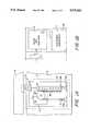
- FIG. 1ashows a side view of a batteryless sensor.
- FIG. 1bshows a front view of the batteryless sensor.
- FIG. 2shows an electronic block diagram of the preferred embodiment of the invention.
- FIG. 3shows an array of coded sensors and a central receiver.
- FIG. 4shows a covert permanent magnet approach for driving the permanent magnet generator of the batteryless sensor.
- FIG. 5shows a micropower receiver block diagram
- FIG. 6is a vector representation of physical variables.
- FIG. 7shows a step up gear arrangement
- the intruderspins the armature of a small permanent magnet dc motor and gear train. Either the field or the magnets are moved relative to each other by the motion of the intrusion that generates the EMF. Translation energy here is converted to rotary motion and a pulley and a gear reduction scheme is used to provide the proper duration signal.
- a dc motoracting as a generator, converts motion to a transient electrical power supply.
- the rotational energy of a door closure/opening motionis converted to the transient electrical power supply.
- the linear motion of a double hung window being openedis converted to the transient electrical power supply.
- the gear trainspins the motor, which acts as the generator, at a high speed for a small linear displacement of a rod located in the frame of the door or window.
- One approachis to use a rack and pinion gear arrangement to convert the linear translation of a rod mounted in the door frame or window into a momentary rotational movement of the generator shaft. This was replaced in later models by a simple pulley and spring arrangement as the preferred mounting arrangement for the sensor. An analysis of the door/rod/pulley and gear train requirements will follow.
- FIGS. 1a and 1bA typical example showing the invention is shown in FIGS. 1a and 1b.
- a batteryless sensor 7is encased in a door jamb 8.
- a timing belt 20 attached to the rod 3 by a collar 40turns a pulley 1 which rotates a motor/generator 4.
- a spring 2applies the proper tension to belt 20 to reset the rod 3 when the door 15 opens, again turning pulley 1 and rotating motor/generator 4 in the opposite direction.
- a stop collar 41 fastened to rod 3is stopped by an inner surface of a container 42 to limit the motion of rod 3.
- a rubber grommet 43cushions the rod 3 at the bottom.
- One end of spring 2is anchored to a block 44, which is fastened to container 42.
- One embodiment of the subject inventionuses a motor/generator and associated gear train 4 manufactured by Buehler Products, Inc., Raleigh, N.C., and identified as 18 V dc, part #1.61.01.347-5 068.
- the gear train accompanying the motor/generator 4requires modification for this application.
- a number of intermediate spur gearsare removed.
- a spaceris added so that the drive gear directly drives the gear that was previously at the end of the chain.
- an approximately one inch displacement of the rod 3 mounted in the door jamb 8turns the pulley 1 about 1/3 turn at a sufficient speed to generate about 10 volts across a 1k ohm load.
- capacitor filteringWith capacitor filtering, a pulse duration of 150 milliseconds (ms) is produced.
- the total cost of all the components, including the motor/generator and gear train 4 and the electronics 5is in the order of tens of dollars for the batteryless sensor 7; this does not include the cost of receiver 6 of FIG. 3, which is estimated in the range of hundreds of dollars.
- FIG. 2An electronic block diagram of the preferred embodiment of the energy source 5 is shown in FIG. 2.
- Rod 3, belt 20 and pulley 1turn the generator/gear train 4 shaft by making physical contact with the door 15 as shown in FIG. 1a.
- the resulting output of generator brushes 9, permanent magnet (PM) field 19is applied to a DF02M, 1 ampere, 200-volt full-wave bridge rectifier 10 producing an unregulated 10 volt peak signal.
- a 100 ⁇ fd, 25 volt filter capacitor 11 and a 5 volt type 1078L05 regulator 12provides an Ecc +5 volt supply, which is constant during the 150 ms pulse burst of VHF energy.
- the 5 volt V cc supplyis connected to both a tone generator 17 (MX503 or 258TC) and a modulator and VHF oscillator 18 which feeds an essentially resonant dipole 16 (i.e., depending on length constraints in the door application).
- the signal radiated by the MC2833 oscillator chip 18is set at 49.845 MHz and receives tones from tone generator 17 from 600 to 2,295 Hz. Four different tones were selected for experimentation and monitored by receiver 6.
- the MC2833 oscillator chip 18is described on page 2-20 of the Motorola Telecommunications Catalogue, DL136 Revision 2, 1989.
- the tone generator 17supplies a sinusoidal tone frequency depending upon the digital code selected, as shown in Table I, as set by small switches D 0 through D 3 .
- One such switch settingis assigned to each batteryless/window sensor 7.
- a central receiver 6 distal to the sensors 7receives the radiated signals.
- the total current drain of the sensor, when activated,is 6.5 ma, corresponding to an actual load of 770 ohms, as compared to our original value of 750 ohms used in the initial testing of the V cc source.
- the chips for the RF modulator/oscillator 18 and tone generator 17were selected to coordinate with the receiver 6 design.
- the frequency deviation of the FM transmissionwas measured to be 2500 Mz.
- FIG. 4a more covert application suggests the use of two opposing magnets 13 and 14 in the door 15 and the door jamb 8 respectively. Then when the door 15 closes, the opposing magnets 13 and 14 would cause the rod 3 connected to one of the magnets 14 to drive the gear train 4 and, in turn, the generator 4 of sensor 7.
- the selection of magnets 13 and 14 and the cosmetic design of the door 15 and jamb 8 to facilitate this conceptwould be used where covertness is important.
- FIG. 3shows one receiver 6 monitoring a large number, f1 through fn, of coded sensors 7.
- the dipole 16transmits the coded rf signals to antenna 22 of receiver 6.
- a signal duration of 150 msis radiated; a minimum signal duration of 20 ms is required for successful detection.
- a block diagram of the receiver 6is provided in FIG. 5.
- the radiated VHF signal from the batteryless sensor 7is received by antenna 22 and filtered by input bandpass filter 23. After amplification in low noise RF amplifier 24, the signal is further filtered by bandpass filter 25 in order to reduce the possibility of adjacent channel interference.
- the filtered RF signalis then fed to a micropower RM receiver chip 27 (Motorola MC 3367) which consists of an internal downconverter (controlled by local oscillator crystal 28), IF amplifier, quadrature detector and lower power audio stages. Filtering is accomplished at the intermediate frequency (IF) of 456 kHz through the use of external resonators 26.
- a micropower RM receiver chip 27Motorola MC 3367
- the audio output from the micropower receiver 27is then passed to a tone decoder 29, an MX-COM MX-013 MetroPageTM decoder chip.
- a reference frequency for the tone decoderis generated by an internal oscillator controlled by external ceramic resonator 30.
- the decoder output 31contains a four-bit digital word containing the ID of the signal, and Data Valid line 32 goes high to indicate that a valid tone has been received.
- Hexadecimal switch 34is used to select one of the 16 possible tone frequencies. If the output 31 from tone detector 29 matches the setting of switch 34, a logical one Detection Output signal 35 is generated by the comparator 33 to activate a monitor 36.
- Receiver 6 poweris obtained from a set of three (3) D-size lithium batteries (not shown). The entire receiver 6, as described above, draws approximately 2 mA at 3.6 Volts.
- the batteryless sensor 7 being usedoperates on a spring-loaded pulley system which produces a voltage signal used to power a transmitter chip. It is important to determine the minimum rotational (angular) velocity required to cause the generator to produce some minimum supply voltage V S .
- step-up gear 58can be added between the generator pulley 56 and rod and belt 50, as shown in FIG. 7. From the following relationships, the improvement that the step-up gear 58 will contribute can be found to be:
- Equation (7)indicates that for a given V m , the rotational speed of the generator 60 can be increased directly by a factor of the ratio of the radii of the two gears 56 and 58.
Landscapes
- Physics & Mathematics (AREA)
- General Physics & Mathematics (AREA)
- Engineering & Computer Science (AREA)
- Computer Networks & Wireless Communication (AREA)
- Business, Economics & Management (AREA)
- Emergency Management (AREA)
- Burglar Alarm Systems (AREA)
Abstract
Description
TABLE I ______________________________________ TONE MODULATOR TABLE. Input Tone Frequencies (f.sub.0 in Hz)* Binary Coded Inputs MX013QA D.sub.3 D.sub.2 D.sub.1 D.sub.0 ______________________________________ 600 0 0 0 0 741 0 0 0 1 882 0 0 1 0 1023 0 0 1 1 1164 0 1 0 0 1305 0 1 0 1 1446 0 1 1 0 1587 0 1 1 1 1728 1 0 0 0 1869 1 0 0 1 2151 1 0 1 0 2435 1 0 1 1 2007 1 1 0 0 2295 1 1 0 1 459 1 1 1 0NOTONE 1 1 1 1 ______________________________________ *Tolerance, ±20 Hz (Minimum)
TABLE II ______________________________________ CURRENT DRAIN @ 5 VOLTS REGULATED. Component # Component Type Current (ma) ______________________________________ 17 MX503 3 12 78L05 0.5 18 MC2833 3.0 ______________________________________
V.sub.d =ω.sub.d r.sub.d
V.sub.m =V.sub.d cos θ=ω.sub.d r.sub.d cos θ(1)
r.sub.d =r.sub.n sec θ, (2)
v.sub.m =ω.sub.d r.sub.n secθ cos θ=ω.sub.d r.sub.n. (3)
V.sub.m =ω.sub.m r.sub.m. (4)
ω.sub.m /ω.sub.d =r.sub.n /r.sub.m. (5)
V.sub.m =ω.sub.m 'r.sub.m '=ω.sub.m r.sub.m, (6)
ω.sub.m /ω.sub.m '=r.sub.m '/r.sub.m. (7)
Claims (10)
Priority Applications (1)
| Application Number | Priority Date | Filing Date | Title |
|---|---|---|---|
| US07/943,715US5317303A (en) | 1992-09-11 | 1992-09-11 | Batteryless sensor used in security applications |
Applications Claiming Priority (1)
| Application Number | Priority Date | Filing Date | Title |
|---|---|---|---|
| US07/943,715US5317303A (en) | 1992-09-11 | 1992-09-11 | Batteryless sensor used in security applications |
Publications (1)
| Publication Number | Publication Date |
|---|---|
| US5317303Atrue US5317303A (en) | 1994-05-31 |
Family
ID=25480142
Family Applications (1)
| Application Number | Title | Priority Date | Filing Date |
|---|---|---|---|
| US07/943,715Expired - Fee RelatedUS5317303A (en) | 1992-09-11 | 1992-09-11 | Batteryless sensor used in security applications |
Country Status (1)
| Country | Link |
|---|---|
| US (1) | US5317303A (en) |
Cited By (31)
| Publication number | Priority date | Publication date | Assignee | Title |
|---|---|---|---|---|
| US5572190A (en)* | 1995-03-22 | 1996-11-05 | Anro Engineering, Inc. | Batteryless sensor used in security applications |
| US6215396B1 (en) | 1996-05-30 | 2001-04-10 | Henry J. Script | Portable motion detector and alarm system and method |
| US6271753B1 (en)* | 2000-03-21 | 2001-08-07 | Kavita M Shukla | Smart lid |
| US6417770B1 (en)* | 2000-06-02 | 2002-07-09 | James F. Sturznickel | Security spacer member for a window |
| US6542078B2 (en)* | 1996-05-30 | 2003-04-01 | Henry J. Script | Portable motion detector and alarm system and method |
| US20030143963A1 (en)* | 2000-05-24 | 2003-07-31 | Klaus Pistor | Energy self-sufficient radiofrequency transmitter |
| GB2385983A (en)* | 2001-06-12 | 2003-09-03 | Roke Manor Research | Switched signalling means |
| US6626267B2 (en)* | 2001-04-30 | 2003-09-30 | The United States Of America As Represented By The Department Of Health And Human Services | Apparatus and method for generating power onboard a hoist conveyance |
| US20040113778A1 (en)* | 1996-05-30 | 2004-06-17 | Script Michael H. | Portable motion detector and alarm system and method |
| US6828909B2 (en) | 1996-05-30 | 2004-12-07 | Guardit Technologies Llc | Portable motion detector and alarm system and method |
| US20050030179A1 (en)* | 1996-05-30 | 2005-02-10 | Script Michael H. | Portable motion detector and alarm system and method |
| US7010369B2 (en) | 1997-11-07 | 2006-03-07 | Hill-Rom Services, Inc. | Medical equipment controller |
| US20070052538A1 (en)* | 2005-08-19 | 2007-03-08 | Nobuyo Sakai | Simple alarm device |
| US20070222584A1 (en)* | 2001-10-11 | 2007-09-27 | Enocean Gmbh | Wireless sensor system |
| US20070252691A1 (en)* | 2006-05-01 | 2007-11-01 | Honeywell International, Inc. | Sensor system including multiple radio frequency identification tags |
| US20090273322A1 (en)* | 2008-05-01 | 2009-11-05 | Robert Bosch Llc | Apparatus and method for generating power for a low current device |
| US20100097778A1 (en)* | 2008-10-21 | 2010-04-22 | Palmer William R | Emergency light station with mechanically activated radio frequency signaling |
| US20100283593A1 (en)* | 2009-05-11 | 2010-11-11 | Ford Global Technologies, Llc | Wireless Seatbelt Monitoring System |
| US20100302025A1 (en)* | 2009-05-26 | 2010-12-02 | Script Michael H | Portable Motion Detector And Alarm System And Method |
| US20110006896A1 (en)* | 2007-08-05 | 2011-01-13 | Thomas Alan Barnett | Security system including wireless self-energizing switch |
| EP2199998A3 (en)* | 2008-12-19 | 2011-04-13 | Dirk Selbach | Radio frame switcher with radio message without energy supply |
| US20110110171A1 (en)* | 2009-11-12 | 2011-05-12 | Em Microelectronic-Marin Sa | Powerless external event detection device |
| US20110119017A1 (en)* | 2009-11-12 | 2011-05-19 | Em Microelectronic-Marin Sa | Self-powered detection device with a non-volatile memory |
| US20110115548A1 (en)* | 2009-11-12 | 2011-05-19 | Em Microelectronic-Marin Sa | Self-powered event detection device |
| US20110115540A1 (en)* | 2009-11-12 | 2011-05-19 | Em Microelectronic-Marin Sa | Self-powered detection device with a non-volatile memory |
| US9199606B1 (en) | 2014-05-15 | 2015-12-01 | Ford Global Technologies | Detecting vehicle door ajar using intrusion sensor |
| CN105742974A (en)* | 2014-12-08 | 2016-07-06 | 济源巨鑫电力设备有限公司 | Antitheft power distribution cabinet |
| US20160337572A1 (en)* | 2015-05-13 | 2016-11-17 | Tyco Fire & Security Gmbh | Self-powered door and window opening sensor |
| USRE46499E1 (en) | 2001-07-03 | 2017-08-01 | Face International Corporation | Self-powered switch initiation system |
| US10096215B1 (en)* | 2017-03-29 | 2018-10-09 | Ambit Microsystems (Shanghai) Ltd. | Non-electrical power operated sensor and monitoring system using the same |
| US11187022B1 (en) | 2001-07-13 | 2021-11-30 | Steven M. Hoffberg | Intelligent door restraint |
Citations (7)
| Publication number | Priority date | Publication date | Assignee | Title |
|---|---|---|---|---|
| US3614760A (en)* | 1968-12-27 | 1971-10-19 | Arthur L Zimmer | Signaling apparatus |
| US3696359A (en)* | 1971-01-26 | 1972-10-03 | Sperry Rand Corp | Intrusion alarm system |
| US3772669A (en)* | 1972-07-14 | 1973-11-13 | Westinghouse Electric Corp | Magnetic pulse generator |
| US3781836A (en)* | 1972-07-14 | 1973-12-25 | Westinghouse Electric Corp | Self-powered wireless intrusion alarm system |
| US3818467A (en)* | 1973-02-01 | 1974-06-18 | Solid State Technology | Damage detection |
| US3827038A (en)* | 1972-10-26 | 1974-07-30 | Solid State Technology | Alarm system |
| US4170005A (en)* | 1977-12-19 | 1979-10-02 | Duke Norman G | Switch operated alarm circuit |
- 1992
- 1992-09-11USUS07/943,715patent/US5317303A/ennot_activeExpired - Fee Related
Patent Citations (7)
| Publication number | Priority date | Publication date | Assignee | Title |
|---|---|---|---|---|
| US3614760A (en)* | 1968-12-27 | 1971-10-19 | Arthur L Zimmer | Signaling apparatus |
| US3696359A (en)* | 1971-01-26 | 1972-10-03 | Sperry Rand Corp | Intrusion alarm system |
| US3772669A (en)* | 1972-07-14 | 1973-11-13 | Westinghouse Electric Corp | Magnetic pulse generator |
| US3781836A (en)* | 1972-07-14 | 1973-12-25 | Westinghouse Electric Corp | Self-powered wireless intrusion alarm system |
| US3827038A (en)* | 1972-10-26 | 1974-07-30 | Solid State Technology | Alarm system |
| US3818467A (en)* | 1973-02-01 | 1974-06-18 | Solid State Technology | Damage detection |
| US4170005A (en)* | 1977-12-19 | 1979-10-02 | Duke Norman G | Switch operated alarm circuit |
Cited By (55)
| Publication number | Priority date | Publication date | Assignee | Title |
|---|---|---|---|---|
| US5572190A (en)* | 1995-03-22 | 1996-11-05 | Anro Engineering, Inc. | Batteryless sensor used in security applications |
| US20040113778A1 (en)* | 1996-05-30 | 2004-06-17 | Script Michael H. | Portable motion detector and alarm system and method |
| US6215396B1 (en) | 1996-05-30 | 2001-04-10 | Henry J. Script | Portable motion detector and alarm system and method |
| US7113091B2 (en) | 1996-05-30 | 2006-09-26 | Script Michael H | Portable motion detector and alarm system and method |
| US6542078B2 (en)* | 1996-05-30 | 2003-04-01 | Henry J. Script | Portable motion detector and alarm system and method |
| US6828909B2 (en) | 1996-05-30 | 2004-12-07 | Guardit Technologies Llc | Portable motion detector and alarm system and method |
| US20050030179A1 (en)* | 1996-05-30 | 2005-02-10 | Script Michael H. | Portable motion detector and alarm system and method |
| US6940405B2 (en) | 1996-05-30 | 2005-09-06 | Guardit Technologies Llc | Portable motion detector and alarm system and method |
| US7010369B2 (en) | 1997-11-07 | 2006-03-07 | Hill-Rom Services, Inc. | Medical equipment controller |
| US6271753B1 (en)* | 2000-03-21 | 2001-08-07 | Kavita M Shukla | Smart lid |
| US20030143963A1 (en)* | 2000-05-24 | 2003-07-31 | Klaus Pistor | Energy self-sufficient radiofrequency transmitter |
| US9887711B2 (en) | 2000-05-24 | 2018-02-06 | Enocean Gmbh | Energy self-sufficient radiofrequency transmitter |
| US20090027167A1 (en)* | 2000-05-24 | 2009-01-29 | Enocean Gmbh | Energy self-sufficient radiofrequency transmitter |
| US9614553B2 (en)* | 2000-05-24 | 2017-04-04 | Enocean Gmbh | Energy self-sufficient radiofrequency transmitter |
| US6417770B1 (en)* | 2000-06-02 | 2002-07-09 | James F. Sturznickel | Security spacer member for a window |
| US6626267B2 (en)* | 2001-04-30 | 2003-09-30 | The United States Of America As Represented By The Department Of Health And Human Services | Apparatus and method for generating power onboard a hoist conveyance |
| GB2385983B (en)* | 2001-06-12 | 2005-01-12 | Roke Manor Research | Switched signalling means |
| GB2385983A (en)* | 2001-06-12 | 2003-09-03 | Roke Manor Research | Switched signalling means |
| USRE46499E1 (en) | 2001-07-03 | 2017-08-01 | Face International Corporation | Self-powered switch initiation system |
| US11187022B1 (en) | 2001-07-13 | 2021-11-30 | Steven M. Hoffberg | Intelligent door restraint |
| US20070222584A1 (en)* | 2001-10-11 | 2007-09-27 | Enocean Gmbh | Wireless sensor system |
| US7777623B2 (en) | 2001-10-11 | 2010-08-17 | Enocean Gmbh | Wireless sensor system |
| US20100097205A1 (en)* | 2003-07-03 | 2010-04-22 | Script Michael H | Portable Motion Detector And Alarm System And Method |
| US20070126576A1 (en)* | 2003-07-03 | 2007-06-07 | Script Michael H | Portable motion detector and alarm system and method |
| US8217789B2 (en) | 2003-07-03 | 2012-07-10 | Script Michael H | Portable motion detector and alarm system and method |
| US7554445B2 (en) | 2003-07-03 | 2009-06-30 | Script Michael H | Portable motion detector and alarm system and method |
| US7414539B2 (en)* | 2005-08-19 | 2008-08-19 | Nobuyo Sakai | Simple alarm device |
| US20070052538A1 (en)* | 2005-08-19 | 2007-03-08 | Nobuyo Sakai | Simple alarm device |
| US7636031B2 (en) | 2006-05-01 | 2009-12-22 | Honeywell International Inc. | Sensor system including multiple radio frequency identification tags |
| US20070252691A1 (en)* | 2006-05-01 | 2007-11-01 | Honeywell International, Inc. | Sensor system including multiple radio frequency identification tags |
| US20110006893A1 (en)* | 2007-08-05 | 2011-01-13 | John Gerard Finch | Notification system utilizing self-energizing switches |
| US20110012730A1 (en)* | 2007-08-05 | 2011-01-20 | John Gerard Finch | Door notification system |
| US20110006896A1 (en)* | 2007-08-05 | 2011-01-13 | Thomas Alan Barnett | Security system including wireless self-energizing switch |
| US8786435B2 (en)* | 2007-08-05 | 2014-07-22 | Enocean Gmbh | Security system including wireless self-energizing switch |
| US7795746B2 (en)* | 2008-05-01 | 2010-09-14 | Robert Bosch Gmbh | Apparatus and method for generating power for a low current device |
| US20090273322A1 (en)* | 2008-05-01 | 2009-11-05 | Robert Bosch Llc | Apparatus and method for generating power for a low current device |
| US20100097778A1 (en)* | 2008-10-21 | 2010-04-22 | Palmer William R | Emergency light station with mechanically activated radio frequency signaling |
| EP2199998A3 (en)* | 2008-12-19 | 2011-04-13 | Dirk Selbach | Radio frame switcher with radio message without energy supply |
| US8289145B2 (en) | 2009-05-11 | 2012-10-16 | Ford Global Technologies, Llc | Wireless seatbelt monitoring system |
| US20100283593A1 (en)* | 2009-05-11 | 2010-11-11 | Ford Global Technologies, Llc | Wireless Seatbelt Monitoring System |
| US8217790B2 (en) | 2009-05-26 | 2012-07-10 | Script Michael H | Portable motion detector and alarm system and method |
| US20100302025A1 (en)* | 2009-05-26 | 2010-12-02 | Script Michael H | Portable Motion Detector And Alarm System And Method |
| US20110119017A1 (en)* | 2009-11-12 | 2011-05-19 | Em Microelectronic-Marin Sa | Self-powered detection device with a non-volatile memory |
| US8422317B2 (en) | 2009-11-12 | 2013-04-16 | Em Microelectronic-Marin Sa | Self-powered detection device with a non-volatile memory |
| US20110115540A1 (en)* | 2009-11-12 | 2011-05-19 | Em Microelectronic-Marin Sa | Self-powered detection device with a non-volatile memory |
| US20110115548A1 (en)* | 2009-11-12 | 2011-05-19 | Em Microelectronic-Marin Sa | Self-powered event detection device |
| US8411505B2 (en) | 2009-11-12 | 2013-04-02 | Em Microelectronic-Marin Sa | Self-powered detection device with a non-volatile memory |
| US20110110171A1 (en)* | 2009-11-12 | 2011-05-12 | Em Microelectronic-Marin Sa | Powerless external event detection device |
| US8422293B2 (en) | 2009-11-12 | 2013-04-16 | Em Microelectronic-Marin Sa | Self-powered event detection device |
| US9199606B1 (en) | 2014-05-15 | 2015-12-01 | Ford Global Technologies | Detecting vehicle door ajar using intrusion sensor |
| CN105742974A (en)* | 2014-12-08 | 2016-07-06 | 济源巨鑫电力设备有限公司 | Antitheft power distribution cabinet |
| CN105742974B (en)* | 2014-12-08 | 2017-11-24 | 济源巨鑫电力设备有限公司 | Antitheft power distribution cabinet |
| US20160337572A1 (en)* | 2015-05-13 | 2016-11-17 | Tyco Fire & Security Gmbh | Self-powered door and window opening sensor |
| US9628692B2 (en)* | 2015-05-13 | 2017-04-18 | Tyco Fire & Security Gmbh | Self-powered door and window opening sensor |
| US10096215B1 (en)* | 2017-03-29 | 2018-10-09 | Ambit Microsystems (Shanghai) Ltd. | Non-electrical power operated sensor and monitoring system using the same |
Similar Documents
| Publication | Publication Date | Title |
|---|---|---|
| US5317303A (en) | Batteryless sensor used in security applications | |
| US5572190A (en) | Batteryless sensor used in security applications | |
| US4532511A (en) | Automatic vehicle identification system and method | |
| US4471343A (en) | Electronic detection systems and methods | |
| US6191687B1 (en) | Wiegand effect energy generator | |
| US3781836A (en) | Self-powered wireless intrusion alarm system | |
| US4288689A (en) | Automatic vehicle identification system and method | |
| US4099168A (en) | Intrusion alarm and emergency illumination apparatus and method | |
| US5132665A (en) | Hub-mounted vehicle back-up alarm | |
| JPH0231356B2 (en) | ||
| JPH08296354A (en) | Improved inductor/antenna for transmitter-receiver | |
| US4074269A (en) | Burglar alarm for use with an automatic garage door opener | |
| US4292629A (en) | Alarm system | |
| US5512874A (en) | Security device | |
| US4074246A (en) | Contact system for sensing closures | |
| FR2270733A1 (en) | Magnetic field vehicle detector unit - receiver detects changes produced in an emitted magnetic field | |
| CA2024521A1 (en) | Theft and vandalism deterrent system | |
| US5532670A (en) | Method of indicating the threat level of an incoming shock to an electronically secured vehicle and apparatus therefore | |
| JP2815142B2 (en) | Method and apparatus for monitoring the movement of an object, especially a motor vehicle | |
| US3976970A (en) | Process and device for analizing and validating signals usable in warning systems for road-signs | |
| RU94023749A (en) | Antitheft device | |
| RU2058906C1 (en) | Vehicle antitheft device | |
| GB2145860A (en) | Security systems | |
| FR2780585A1 (en) | APPARATUS AND METHOD FOR DETECTION AND READING OF IDENTIFICATION RESPONDERS IN A CONTROLLED PASS | |
| Ross et al. | Batteryless Sensor for Intrusion Detection and Assessment of Threats. |
Legal Events
| Date | Code | Title | Description |
|---|---|---|---|
| AS | Assignment | Owner name:MULTISPECTRAL SOLUTIONS, INC., MARYLAND Free format text:ASSIGNMENT OF A PART OF ASSIGNORS INTEREST;ASSIGNORS:ROSS, GERALD F.;MARA, RICHARD M.;ROBBINS, KENNETH W.;AND OTHERS;REEL/FRAME:006311/0095 Effective date:19920911 Owner name:ANRO ENGINEERING, INC., MASSACHUSETTS Free format text:ASSIGNMENT OF A PART OF ASSIGNORS INTEREST;ASSIGNORS:ROSS, GERALD F.;MARA, RICHARD M.;ROBBINS, KENNETH W.;AND OTHERS;REEL/FRAME:006311/0095 Effective date:19920911 | |
| AS | Assignment | Owner name:ANRO ENGINEERING, INC., MASSACHUSETTS Free format text:ASSIGNMENT OF ASSIGNORS INTEREST;ASSIGNOR:MULTISPECTRAL SOLUTIONS, INC.;REEL/FRAME:007319/0363 Effective date:19950106 | |
| FPAY | Fee payment | Year of fee payment:4 | |
| REMI | Maintenance fee reminder mailed | ||
| LAPS | Lapse for failure to pay maintenance fees | ||
| STCH | Information on status: patent discontinuation | Free format text:PATENT EXPIRED DUE TO NONPAYMENT OF MAINTENANCE FEES UNDER 37 CFR 1.362 | |
| FP | Lapsed due to failure to pay maintenance fee | Effective date:20020531 |