US5316798A - Method of making a cylindrical sleeve structure, particularly cover for an offset cylinder in a rotary printing machine - Google Patents
Method of making a cylindrical sleeve structure, particularly cover for an offset cylinder in a rotary printing machineDownload PDFInfo
- Publication number
- US5316798A US5316798AUS07/864,407US86440792AUS5316798AUS 5316798 AUS5316798 AUS 5316798AUS 86440792 AUS86440792 AUS 86440792AUS 5316798 AUS5316798 AUS 5316798A
- Authority
- US
- United States
- Prior art keywords
- carrier
- coating layer
- substance
- applying
- cover layer
- Prior art date
- Legal status (The legal status is an assumption and is not a legal conclusion. Google has not performed a legal analysis and makes no representation as to the accuracy of the status listed.)
- Expired - Lifetime
Links
Images
Classifications
- B—PERFORMING OPERATIONS; TRANSPORTING
- B41—PRINTING; LINING MACHINES; TYPEWRITERS; STAMPS
- B41N—PRINTING PLATES OR FOILS; MATERIALS FOR SURFACES USED IN PRINTING MACHINES FOR PRINTING, INKING, DAMPING, OR THE LIKE; PREPARING SUCH SURFACES FOR USE AND CONSERVING THEM
- B41N6/00—Mounting boards; Sleeves Make-ready devices, e.g. underlays, overlays; Attaching by chemical means, e.g. vulcanising
- B—PERFORMING OPERATIONS; TRANSPORTING
- B29—WORKING OF PLASTICS; WORKING OF SUBSTANCES IN A PLASTIC STATE IN GENERAL
- B29C—SHAPING OR JOINING OF PLASTICS; SHAPING OF MATERIAL IN A PLASTIC STATE, NOT OTHERWISE PROVIDED FOR; AFTER-TREATMENT OF THE SHAPED PRODUCTS, e.g. REPAIRING
- B29C35/00—Heating, cooling or curing, e.g. crosslinking or vulcanising; Apparatus therefor
- B29C35/18—Cold vulcanisation
- B—PERFORMING OPERATIONS; TRANSPORTING
- B29—WORKING OF PLASTICS; WORKING OF SUBSTANCES IN A PLASTIC STATE IN GENERAL
- B29C—SHAPING OR JOINING OF PLASTICS; SHAPING OF MATERIAL IN A PLASTIC STATE, NOT OTHERWISE PROVIDED FOR; AFTER-TREATMENT OF THE SHAPED PRODUCTS, e.g. REPAIRING
- B29C44/00—Shaping by internal pressure generated in the material, e.g. swelling or foaming ; Producing porous or cellular expanded plastics articles
- B29C44/02—Shaping by internal pressure generated in the material, e.g. swelling or foaming ; Producing porous or cellular expanded plastics articles for articles of definite length, i.e. discrete articles
- B29C44/022—Foaming unrestricted by cavity walls, e.g. without using moulds or using only internal cores
- B—PERFORMING OPERATIONS; TRANSPORTING
- B29—WORKING OF PLASTICS; WORKING OF SUBSTANCES IN A PLASTIC STATE IN GENERAL
- B29C—SHAPING OR JOINING OF PLASTICS; SHAPING OF MATERIAL IN A PLASTIC STATE, NOT OTHERWISE PROVIDED FOR; AFTER-TREATMENT OF THE SHAPED PRODUCTS, e.g. REPAIRING
- B29C44/00—Shaping by internal pressure generated in the material, e.g. swelling or foaming ; Producing porous or cellular expanded plastics articles
- B29C44/02—Shaping by internal pressure generated in the material, e.g. swelling or foaming ; Producing porous or cellular expanded plastics articles for articles of definite length, i.e. discrete articles
- B29C44/12—Incorporating or moulding on preformed parts, e.g. inserts or reinforcements
- B—PERFORMING OPERATIONS; TRANSPORTING
- B41—PRINTING; LINING MACHINES; TYPEWRITERS; STAMPS
- B41N—PRINTING PLATES OR FOILS; MATERIALS FOR SURFACES USED IN PRINTING MACHINES FOR PRINTING, INKING, DAMPING, OR THE LIKE; PREPARING SUCH SURFACES FOR USE AND CONSERVING THEM
- B41N10/00—Blankets or like coverings; Coverings for wipers for intaglio printing
- B41N10/02—Blanket structure
- B—PERFORMING OPERATIONS; TRANSPORTING
- B29—WORKING OF PLASTICS; WORKING OF SUBSTANCES IN A PLASTIC STATE IN GENERAL
- B29K—INDEXING SCHEME ASSOCIATED WITH SUBCLASSES B29B, B29C OR B29D, RELATING TO MOULDING MATERIALS OR TO MATERIALS FOR MOULDS, REINFORCEMENTS, FILLERS OR PREFORMED PARTS, e.g. INSERTS
- B29K2075/00—Use of PU, i.e. polyureas or polyurethanes or derivatives thereof, as moulding material
- B—PERFORMING OPERATIONS; TRANSPORTING
- B29—WORKING OF PLASTICS; WORKING OF SUBSTANCES IN A PLASTIC STATE IN GENERAL
- B29K—INDEXING SCHEME ASSOCIATED WITH SUBCLASSES B29B, B29C OR B29D, RELATING TO MOULDING MATERIALS OR TO MATERIALS FOR MOULDS, REINFORCEMENTS, FILLERS OR PREFORMED PARTS, e.g. INSERTS
- B29K2083/00—Use of polymers having silicon, with or without sulfur, nitrogen, oxygen, or carbon only, in the main chain, as moulding material
- B—PERFORMING OPERATIONS; TRANSPORTING
- B29—WORKING OF PLASTICS; WORKING OF SUBSTANCES IN A PLASTIC STATE IN GENERAL
- B29K—INDEXING SCHEME ASSOCIATED WITH SUBCLASSES B29B, B29C OR B29D, RELATING TO MOULDING MATERIALS OR TO MATERIALS FOR MOULDS, REINFORCEMENTS, FILLERS OR PREFORMED PARTS, e.g. INSERTS
- B29K2105/00—Condition, form or state of moulded material or of the material to be shaped
- B29K2105/06—Condition, form or state of moulded material or of the material to be shaped containing reinforcements, fillers or inserts
- B29K2105/16—Fillers
- B—PERFORMING OPERATIONS; TRANSPORTING
- B29—WORKING OF PLASTICS; WORKING OF SUBSTANCES IN A PLASTIC STATE IN GENERAL
- B29L—INDEXING SCHEME ASSOCIATED WITH SUBCLASS B29C, RELATING TO PARTICULAR ARTICLES
- B29L2031/00—Other particular articles
- B29L2031/32—Wheels, pinions, pulleys, castors or rollers, Rims
- B29L2031/324—Rollers or cylinders having an axial length of several times the diameter, e.g. embossing, pressing or printing
- B—PERFORMING OPERATIONS; TRANSPORTING
- B41—PRINTING; LINING MACHINES; TYPEWRITERS; STAMPS
- B41N—PRINTING PLATES OR FOILS; MATERIALS FOR SURFACES USED IN PRINTING MACHINES FOR PRINTING, INKING, DAMPING, OR THE LIKE; PREPARING SUCH SURFACES FOR USE AND CONSERVING THEM
- B41N2210/00—Location or type of the layers in multi-layer blankets or like coverings
- B41N2210/04—Intermediate layers
- B—PERFORMING OPERATIONS; TRANSPORTING
- B41—PRINTING; LINING MACHINES; TYPEWRITERS; STAMPS
- B41N—PRINTING PLATES OR FOILS; MATERIALS FOR SURFACES USED IN PRINTING MACHINES FOR PRINTING, INKING, DAMPING, OR THE LIKE; PREPARING SUCH SURFACES FOR USE AND CONSERVING THEM
- B41N2210/00—Location or type of the layers in multi-layer blankets or like coverings
- B41N2210/14—Location or type of the layers in multi-layer blankets or like coverings characterised by macromolecular organic compounds
Definitions
- German Patent Disclosure Document DE-OS 27 08 689Textbook, Walenski: “Einbowung in den Offset réelle” ("Introduction to Offset Printing"), published by Hanns Eggen GmbH & Co. KG, Hannover, Fed. Rep. Germany, pp. 262, 263. CRC Handbook of Chemistry and Physics, 62nd edition, 1981, page E-32.
- the present inventionrelates to a method of making a cylindrical sleeve structure for an offset cylinder of a rotary printing machine, and more particularly to such a sleeve structure which has a resiliently compressible cover.
- Blanket cylinders of offset printing machinescan be an endless, cylindrical sleeve or an interrupted cover, clamped in a clamping groove.
- German Patent Disclosure Document DE-OS 27 08 689describes an offset printing machine having a continuous cylindrical cover which is replaceable applied on an offset printing cylinder. Elastic materials are used for the coating.
- a cylindrical carrierhas a cylindrical cover placed thereover which is formed of a multi-component material having a foam of a base substance which becomes volume compressible during its application.
- the foam substanceincludes a blowing agent and an inhibitor, both applied by free foaming on the surface of the carrier.
- the carrieris rotated and a thixotropic base substance, in liquid form, is applied thereon in a spiral stripe, for example by axially feeding or translating the carrier as it rotates, the thixotropic substance, including the blowing agent and inhibitor, being applied in an essentially spiral layer in a condition in which it is still spreadable and somewhat flowable to form a uniform cover over the cylindrical carrier.
- the resulting structuremade by the method, has the advantage of low damping and high rebound or bounce-back elasticity.
- Free foamingas used herein means that the material is applied and can foam as it is being applied, without constraint by a mold, that is, is free to form microcells or micropores, not externally constrained but inherent in the material as it is formed and, if of the curing type, as it foams and cures.
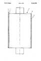
- the single FIGUREis a highly schematic cross-sectional view through a carrier sleeve forming an offset sleeve cover for an offset cylinder of a rotary offset printing machine, in which the offset cylinder has been omitted and is shown, schematically, only by its center line and shaft extensions.
- An offset printing machine cylinder 1for example as used in rotary offset printing machines to transfer a printed image from an inked plate on a substrate has two shaft extensions for supporting the cylinder in suitable bearings in side walls of a printing machine.
- the cylinderhas a replaceable sleeve 2 thereon.
- the replaceable sleeve 2has a substrate or carrier layer 5 and a volume compressible coating layer 3.
- a cover layer 4is applied on top of the volume compressible layer 3.
- microcells or microporesare formed in the volume compressible layer 3, are located within the material, and formed during application of the layer 3; they are not applied externally from the outside.
- the cover layer 4is not strictly necessary but is usually provided.
- the cylindrical body 1may be, itself, a hollow cylindrical sleeve-like structure; the sleeve 2 likewise, may be a separate cylindrical structure. Either one of the cylindrical structures may be made of plastic, for example reinforced with carbon or graphite fibers or the like; the carrier 5 may also be a metallic tube or sleeve, for example made of aluminum.
- the wall thickness of the carrier 5, depending on the material,is, preferably, between 0.02 and 0.3 mm.
- the volume compressible layer 3, which forms the base for the cover layer 4,is, preferably, a material based on a polyol, such as polyurethane; or a material based on a silicone.
- Layer 3preferably, has a thickness of between 1 to 5 mm, although it may be somewhat thinner or thicker.
- the top cover layer 4, if used,can be applied on the volume compressible base layer 3.
- Cover layer 4is not volume compressible and may, for example, be made of a material based on polyurethane, or based on rubber. The thickness of the layer 4 is usually less than 0.5 mm and may be as small as only a few hundredths mm.
- the materials used to generate the volume compressible base layer 3are exothermic upon cross-linking by addition of cross-linking or curing agents, which means that, upon cross-linking, heat is generated.
- the base layer 3, in accordance with a feature of the invention,will have microcells or micropores of less than 0.01 mm diameter.
- the volumetric portion of the cellsshould be greater than 50% and, preferably, the number of their occurrence should increase towards the outer circumference.
- the volume compressible layer 3has a density of between about 0.30 g/cm 3 and 0.65 g/cm 3 .
- the rise time or build-up time of the material of the volume compressible layer 3should be between about 2 and 15 seconds.
- the portion of closed pores or cells formed upon manufacture of the layershould be greater than the portion of the pores or cells which are open; in other words, there should be more closed pores than pores which are connected by ducts or channels or other communication, or which terminate at the surface. Thus, the percentage of closed cells of the total cells will be greater than 50%.
- the contacting portion of the compact cover layer 4 on the composite layeris, preferably, greater than 50%.
- the damping of the volume compressible layer 3is smaller than 25%, or, in other words, the rebound elasticity, which is the reciprocal, greater than 75%.
- the volume compressible layer 3permits, in a desirable manner, consideration of spring characteristics in printing. From a spring diagram of surface pressure, width of printing impression lines, and the path distance thereto, the specific desired characteristics can be determined.
- the size of the cells or poresshould be less than 0.01 mm, and the relationship of pore volume to the volume of the wall thickness, that is, the thickness of the substance of the wall surrounding the pores, should be greater than 1.5:1 and, preferably, about 2.5:1.
- the rebound or bounce-back elasticity, i.e. recovery after a compressive force has been released,will be more than 95%, and the remanent deformation due to pressure will be less than 5% and, desirably and preferably, usually less than 2%.
- the layeris volume compressible throughout the entire thickness thereof.
- a thixotropic base materialprovided in form of a gel within a container is stirred until it becomes readily flowable and liquid. Due to the thixotropic characteristics of the material, it will revert to a gel after stirring.
- the materialfurther, can be filled, thickened and reinforced by additives to increase its consistency and "body”.
- the volume compressible layeris applied in liquid form of the thixotropic material on the carrier sleeve, preferably by rotating and axially feeding the carrier sleeve, so that the material is applied in spiral layers, and can still flow so that no bulges, ridges, or free spots will form.
- the materialthen, solidifies. By use of suitable hardeners, the solidifying step can be controlled.
- a cylindrical carrier sleevefor rotary printing machines, particularly offset printing machines, which have a continuous, that is seamless, coating of plastic material which is formed with separate micropores or microcells which are not connected among each other.
- a suitable thixotropic materialis a material based on a polyol with silicic acid. Suitable additives are chalk or talcum.
- the inventionprovides the possibility to form a volume compressible layer which can foam freely as it is applied, that is, it does not require a molding form, as known methods do.
- expanding agentswhich includes materials commonly referred to as blowing agents or foaming agents and inhibitors
- the characteristics of the material using the foregoing processcan be controlled by suitable stirring and adding of curing or hardening agents, so that the desired size and number of micropores or microcells will result.
- the hardeners to be usedinfluence the resting or curing time which, preferably, is between 2 to 10 seconds.
- the expanding or blowing agents and the inhibitorswhich also are operative as activators, initiate and will result in a closed structure, for example at the surface, forming an elastic foam.
- the present inventionprovides a cylindrical carrier sleeve for rotary printing machines, particularly offset printing machines, which has a closed, continuous, that is, seamless outer coating of plastic material, formed with separate, that is, not connected microcells or micropores.
- rotary printing machinesparticularly offset printing machines
- a closed, continuousthat is, seamless outer coating of plastic material, formed with separate, that is, not connected microcells or micropores.
- Inhibitorsare activators with indirect action.
- a suitable inhibitoris a tertiary amine.
- the inhibitorscontrol gelling of the thixotropic materials which are used.
- Expanding, blowing, propelling or foaming agentsare materials which, themselves, liberate gas, for example methylenechloride.
- the cover layer 4can be applied in a suitable and well known manner, for example also using the above-described principle and method.
- the size of the cellscan be influenced decisively by the energy applied during the stirring and the speed of stirring as the material is prepared.
- the distribution of the space within the layer 3depends, temporally, on the application time, the foaming rise time, the speed of rotation of the carrier, and the hardening time.
- the cover layer 4is preferably formed by a compact elastomer, with a surface which is a fine smooth surface with the required roughness or, better expressed, the required smoothness.
- the thickness of the layer 4can be less than 0.5 mm, and may be made of any suitable material, such as a rubber-based material, a silicone or a polyurethane.
- the sleeve 2 so formedhas advantages with respect to the construction of printing machines, as well as advantages in use, that is, upon printing. Additionally, it can be made inexpensively.
- Seamless offset sleevesare not subjected to the stresses arising on changeable compression and tension loading, which interferes with print quality, register, and output; additionally, they permit a paper path which is gentle on the paper.
- the power requirement to drive the machineis reduced. It is not necessary to form the machine cylinder which carries the sleeve as a massive solid element, which is frequently the case in current machines.
- the volume compressible materialdoes not "knead"; thus, all problems of the formation of bulges, ridges and the like, are eliminated.
- the coverpreferably made according to the described method, has a further advantage: From a printing quality point of view, excellent reproduction is obtainable because the impression line only compresses the layer of the carrier material, without spreading out, since no material is displaced. This advantage is obtainable with a seamless or continuous cover, that is, one without being clamped in a clamping groove. As a result, the impression line is precisely transferred from a printing plate on the offset cylinder and by the offset cylinder precisely transferred to the printing substrate.
- the springy characteristics or resiliency characteristicsnamely compression and reset to normal or uncompressed dimension, is a gas dynamic process which is essentially isothermal, that is, no heat of any consequence is liberated. Heating of the gas by compression is balanced by cooling upon expansion of the gas after the compression is released.
- the covercan be made quite inexpensively, and has the additional advantage that, due to the circular geometry, it can be easily handled.
- the shape and the positionis predetermined. This is in contrast to blankets which are stretched over a cylinder.
- the size of the covercan be easily predetermined since the material can be so influenced that its behavior, that is, the behavior of the compressible layer upon compression, is determinable.
- Another advantage which contributes to low costis that the material cures in an exothermal reaction, that is, it liberates heat. This is in contrast to vulcanizing a rubber blanket, which requires heat. No holding or counter mold or form is necessary as, for example, in the manufacture of generally known polyurethane rollers, which are cast with compact material between a mold core or form and a mold shell.
- the inventionis particularly applicable to cylindrical carrier sleeves, that is, sleeves which are coated and which can receive printed image subject matter, to replace prior art rubber blankets, for transfer of the printed image on a substrate, for example in the well known offset process.
- the coating, and the method thereof, in accordance with the present inventionmay be applied also to other types of cylinders or rollers, for example to any kind of essentially cylindrical elements, for example for image transfer via a cylinder, as well as for other applications, for example as ink application rollers, rollers, or roller elements within various roller trains utilized in printing machines.
- a carrier sleeve of 22 cm diameter and 100 cm lengthis placed in a holder which permits the carrier sleeve to rotate, and carry out axially longitudinal movement with respect to a coating application head.
- the cylinderwas rotated at a speed of 60 rpm, and fed longitudinally at a rate of 30 meters per hour.
- the coating of the thixotropic materialwas provided by mixing 1 kg polyurethane with 0.370 kg isocyanate, to obtain a gel which, by stirring, was rendered liquid. Additives of talcum of 0.04 kg to increase the "body" were added during mixing.
- a foaming agentnamely a FRIGEN (Reg. Trademark) gas of 0.5 kg as well as a curing agent, a tertiary amino compound of 0.05 kg was added to the stirred liquid, and immediately applied by an application head or spreader on the now rotating and axially fed cylinder 5.
- the cylindercontinued to rotate until it was coated through its entire length, and then was continued to be rotated, without application of further coating material, for 2 minutes. The entire process was carried out at room temperature. A coating of 3 mm thickness was obtained.
- the layer 4was applied over the foamed layer 3, formed upon curing. Alternatively, the layer 4 can be applied before the layer is entirely cured and while it is still slightly tacky.
- FRIGENis a Registered Trademark for fluorocarbon propelling agents available from Hoechst Aktiengesellschaft, Frankfurt/Main, Germany.
- the layer 4was formed of compact polyurethane, namely Vulkolan. (Reg. Trademark)
- the thickness of the layer 3was 2.5 mm, the thickness of the layer 4 was 0.5 mm, and the density of the volume compressible layer 3 was 0.4 g/cm 3 , with a damping of the volume compressible layer 3 of 3% and a rebound elasticity of over 95%.
- a roller as explained in Example 1was similarly coated, except that the coating composition was: 1 kg of base material with 0.4 kg gel forming material; the foaming or blowing agent and inhibitor were: 0.3 kg of water or a polyvalent alcohol with R11 or R12 gas.
- R11 and R12are fluorocarbon refrigerants, the detailed specifications of which are listed in the CRC Handbook of Chemistry and Physics, in the 67th edition, page E32, "Physical properties of fluorocarbon refrigerants", and well known as such.
- the "R:stands for "refrigerant”.
- the layers 3 and 4were similar to the layers of Example 1, except that the density was 0.3 g/cm 3 and the rebound elasticity was 98%.
- a roller as explained in Example 1was similarly coated, except that the coating composition was: 1 kg of base material with 0.4 kg gel forming material; the foaming or blowing agent and inhibitor were: 0.3 kg of water or a polyvalent alcohol with R11 gas or R12 gas.
- the layers 3 and 4were similar to the layers of Example 1, except that the density was 0.35 g/cm 3 and the rebound elasticity was 96% and 90° Shore A.
Landscapes
- Physics & Mathematics (AREA)
- Health & Medical Sciences (AREA)
- Oral & Maxillofacial Surgery (AREA)
- Thermal Sciences (AREA)
- Printing Plates And Materials Therefor (AREA)
Abstract
Description
This is a continuation-in-part application of U.S. application Ser. No. 07/494,129, filed Mar. 15, 1990, now abandoned.
German Patent Disclosure Document DE-OS 27 08 689. Textbook, Walenski: "Einfuhrung in den Offsetdruck" ("Introduction to Offset Printing"), published by Hanns Eggen GmbH & Co. KG, Hannover, Fed. Rep. Germany, pp. 262, 263. CRC Handbook of Chemistry and Physics, 62nd edition, 1981, page E-32.
The present invention relates to a method of making a cylindrical sleeve structure for an offset cylinder of a rotary printing machine, and more particularly to such a sleeve structure which has a resiliently compressible cover.
Blanket cylinders of offset printing machines can be an endless, cylindrical sleeve or an interrupted cover, clamped in a clamping groove. German Patent Disclosure Document DE-OS 27 08 689 describes an offset printing machine having a continuous cylindrical cover which is replaceable applied on an offset printing cylinder. Elastic materials are used for the coating.
The referenced textbook, Walenski: "Einfuhrung in den Offsetdruck" ("Introduction to Offset Printing"), published by Hanns Eggen GmbH & Co. KG, Hannover, Fed. Rep. Germany, pp. 262, 263, describes rubber blankets for use in customary offset rotary printing machines which are elastically deformable, but not volume compressible. Rubber blankets of this type are referred to as incompressible or non-compressible blankets. Only gaseous materials are volume compressible. Liquids and solid materials are not volume compressible. Rubber blankets having intermediate rubber layers of micro-compressible, volume compressible material, connected by air channels or pores, have not found acceptance in offset printing machine sleeves. Use of customary, that is, elastic but not volume compressible material, is not suitable since, in contrast to blankets which are clamped in clamping grooves, continuous sleeves do not permit release of tension or bulges which form in operation. Practical use of coated, continuous carrier sleeves, particularly for wide or axially long printing cylinders was not possible. Such sleeves could not be made, either in form of a compact inherently elastic sleeve, or as an elastic coating on a sleeve, and foamed coatings were impossible to use.
Customary materials in order to make foamed structures, such as cast polyurethane, had been considered. Yet, use of previously known volume compressible material was not economically possible, even if, theoretically, the technical use would have been possible.
It is an object to provide method to make a cylindrical sleeve in which known difficulties of offset print subject matter carriers do not arise, which are economical in manufacture and provide for desirable roll-off and printing to thereby result in improved printing quality of a resulting printed product.
Briefly, a cylindrical carrier has a cylindrical cover placed thereover which is formed of a multi-component material having a foam of a base substance which becomes volume compressible during its application. The foam substance includes a blowing agent and an inhibitor, both applied by free foaming on the surface of the carrier. In accordance with a feature of the invention, the carrier is rotated and a thixotropic base substance, in liquid form, is applied thereon in a spiral stripe, for example by axially feeding or translating the carrier as it rotates, the thixotropic substance, including the blowing agent and inhibitor, being applied in an essentially spiral layer in a condition in which it is still spreadable and somewhat flowable to form a uniform cover over the cylindrical carrier.
The resulting structure, made by the method, has the advantage of low damping and high rebound or bounce-back elasticity.
"Free foaming" as used herein means that the material is applied and can foam as it is being applied, without constraint by a mold, that is, is free to form microcells or micropores, not externally constrained but inherent in the material as it is formed and, if of the curing type, as it foams and cures.
The single FIGURE is a highly schematic cross-sectional view through a carrier sleeve forming an offset sleeve cover for an offset cylinder of a rotary offset printing machine, in which the offset cylinder has been omitted and is shown, schematically, only by its center line and shaft extensions.
An offset printing machine cylinder 1, for example as used in rotary offset printing machines to transfer a printed image from an inked plate on a substrate has two shaft extensions for supporting the cylinder in suitable bearings in side walls of a printing machine. The cylinder has areplaceable sleeve 2 thereon. Thereplaceable sleeve 2 has a substrate orcarrier layer 5 and a volume compressible coating layer 3. A cover layer 4 is applied on top of the volume compressible layer 3.
In accordance with the present invention, microcells or micropores are formed in the volume compressible layer 3, are located within the material, and formed during application of the layer 3; they are not applied externally from the outside.
The cover layer 4 is not strictly necessary but is usually provided.
The cylindrical body 1 may be, itself, a hollow cylindrical sleeve-like structure; thesleeve 2 likewise, may be a separate cylindrical structure. Either one of the cylindrical structures may be made of plastic, for example reinforced with carbon or graphite fibers or the like; thecarrier 5 may also be a metallic tube or sleeve, for example made of aluminum. The wall thickness of thecarrier 5, depending on the material, is, preferably, between 0.02 and 0.3 mm.
The volume compressible layer 3, which forms the base for the cover layer 4, is, preferably, a material based on a polyol, such as polyurethane; or a material based on a silicone. Layer 3, preferably, has a thickness of between 1 to 5 mm, although it may be somewhat thinner or thicker. The top cover layer 4, if used, can be applied on the volume compressible base layer 3. Cover layer 4 is not volume compressible and may, for example, be made of a material based on polyurethane, or based on rubber. The thickness of the layer 4 is usually less than 0.5 mm and may be as small as only a few hundredths mm.
In accordance with a feature of the invention, the materials used to generate the volume compressible base layer 3 are exothermic upon cross-linking by addition of cross-linking or curing agents, which means that, upon cross-linking, heat is generated.
The base layer 3, in accordance with a feature of the invention, will have microcells or micropores of less than 0.01 mm diameter. The volumetric portion of the cells should be greater than 50% and, preferably, the number of their occurrence should increase towards the outer circumference. The volume compressible layer 3 has a density of between about 0.30 g/cm3 and 0.65 g/cm3. The rise time or build-up time of the material of the volume compressible layer 3 should be between about 2 and 15 seconds. The portion of closed pores or cells formed upon manufacture of the layer should be greater than the portion of the pores or cells which are open; in other words, there should be more closed pores than pores which are connected by ducts or channels or other communication, or which terminate at the surface. Thus, the percentage of closed cells of the total cells will be greater than 50%.
The contacting portion of the compact cover layer 4 on the composite layer is, preferably, greater than 50%. The damping of the volume compressible layer 3 is smaller than 25%, or, in other words, the rebound elasticity, which is the reciprocal, greater than 75%. The volume compressible layer 3 permits, in a desirable manner, consideration of spring characteristics in printing. From a spring diagram of surface pressure, width of printing impression lines, and the path distance thereto, the specific desired characteristics can be determined. The size of the cells or pores should be less than 0.01 mm, and the relationship of pore volume to the volume of the wall thickness, that is, the thickness of the substance of the wall surrounding the pores, should be greater than 1.5:1 and, preferably, about 2.5:1. The rebound or bounce-back elasticity, i.e. recovery after a compressive force has been released, will be more than 95%, and the remanent deformation due to pressure will be less than 5% and, desirably and preferably, usually less than 2%.
It is a specific advantage of the sleeve construction that the layer is volume compressible throughout the entire thickness thereof.
In accordance with a preferred feature of the invention, a thixotropic base material, provided in form of a gel within a container is stirred until it becomes readily flowable and liquid. Due to the thixotropic characteristics of the material, it will revert to a gel after stirring. The material, further, can be filled, thickened and reinforced by additives to increase its consistency and "body". In accordance with the invention, the volume compressible layer is applied in liquid form of the thixotropic material on the carrier sleeve, preferably by rotating and axially feeding the carrier sleeve, so that the material is applied in spiral layers, and can still flow so that no bulges, ridges, or free spots will form. The material, then, solidifies. By use of suitable hardeners, the solidifying step can be controlled.
In accordance with the invention, generally, a cylindrical carrier sleeve is provided for rotary printing machines, particularly offset printing machines, which have a continuous, that is seamless, coating of plastic material which is formed with separate micropores or microcells which are not connected among each other.
A suitable thixotropic material is a material based on a polyol with silicic acid. Suitable additives are chalk or talcum.
In contrast to known processes, the invention provides the possibility to form a volume compressible layer which can foam freely as it is applied, that is, it does not require a molding form, as known methods do. By use of expanding agents, which includes materials commonly referred to as blowing agents or foaming agents and inhibitors, the characteristics of the material using the foregoing process can be controlled by suitable stirring and adding of curing or hardening agents, so that the desired size and number of micropores or microcells will result. The hardeners to be used influence the resting or curing time which, preferably, is between 2 to 10 seconds. The expanding or blowing agents and the inhibitors, which also are operative as activators, initiate and will result in a closed structure, for example at the surface, forming an elastic foam. The volume, compactness, size of cells, proportion of cell walls to overall volume, and the proportion of cells to overall volume can be varied within wide ranges, easily determined by experiments to provide the desired material. Basically, the present invention provides a cylindrical carrier sleeve for rotary printing machines, particularly offset printing machines, which has a closed, continuous, that is, seamless outer coating of plastic material, formed with separate, that is, not connected microcells or micropores. The process described in detail above is a preferred method of its manufacture.
Inhibitors, as used herein, are activators with indirect action. A suitable inhibitor is a tertiary amine. The inhibitors control gelling of the thixotropic materials which are used. Expanding, blowing, propelling or foaming agents are materials which, themselves, liberate gas, for example methylenechloride.
The cover layer 4 can be applied in a suitable and well known manner, for example also using the above-described principle and method.
The size of the cells can be influenced decisively by the energy applied during the stirring and the speed of stirring as the material is prepared. The distribution of the space within the layer 3 depends, temporally, on the application time, the foaming rise time, the speed of rotation of the carrier, and the hardening time.
The cover layer 4 is preferably formed by a compact elastomer, with a surface which is a fine smooth surface with the required roughness or, better expressed, the required smoothness. The thickness of the layer 4 can be less than 0.5 mm, and may be made of any suitable material, such as a rubber-based material, a silicone or a polyurethane.
Thesleeve 2 so formed has advantages with respect to the construction of printing machines, as well as advantages in use, that is, upon printing. Additionally, it can be made inexpensively.
Seamless offset sleeves are not subjected to the stresses arising on changeable compression and tension loading, which interferes with print quality, register, and output; additionally, they permit a paper path which is gentle on the paper. The power requirement to drive the machine, further, is reduced. It is not necessary to form the machine cylinder which carries the sleeve as a massive solid element, which is frequently the case in current machines. In accordance with the present invention, the volume compressible material does not "knead"; thus, all problems of the formation of bulges, ridges and the like, are eliminated.
The cover, preferably made according to the described method, has a further advantage: From a printing quality point of view, excellent reproduction is obtainable because the impression line only compresses the layer of the carrier material, without spreading out, since no material is displaced. This advantage is obtainable with a seamless or continuous cover, that is, one without being clamped in a clamping groove. As a result, the impression line is precisely transferred from a printing plate on the offset cylinder and by the offset cylinder precisely transferred to the printing substrate. The springy characteristics or resiliency characteristics, namely compression and reset to normal or uncompressed dimension, is a gas dynamic process which is essentially isothermal, that is, no heat of any consequence is liberated. Heating of the gas by compression is balanced by cooling upon expansion of the gas after the compression is released.
The substantially smaller mechanical stresses which are applied on thecover layer 2, and especially the elimination of kneading, and pushing and pulling as well as stretching and clamping of the cover, which occurred in the prior art, and in combination with the highly wear accepting material, provides for long operating time of thecover 2.
The cover can be made quite inexpensively, and has the additional advantage that, due to the circular geometry, it can be easily handled. The shape and the position is predetermined. This is in contrast to blankets which are stretched over a cylinder. Likewise, the size of the cover can be easily predetermined since the material can be so influenced that its behavior, that is, the behavior of the compressible layer upon compression, is determinable. Another advantage which contributes to low cost is that the material cures in an exothermal reaction, that is, it liberates heat. This is in contrast to vulcanizing a rubber blanket, which requires heat. No holding or counter mold or form is necessary as, for example, in the manufacture of generally known polyurethane rollers, which are cast with compact material between a mold core or form and a mold shell.
The invention is particularly applicable to cylindrical carrier sleeves, that is, sleeves which are coated and which can receive printed image subject matter, to replace prior art rubber blankets, for transfer of the printed image on a substrate, for example in the well known offset process. The coating, and the method thereof, in accordance with the present invention may be applied also to other types of cylinders or rollers, for example to any kind of essentially cylindrical elements, for example for image transfer via a cylinder, as well as for other applications, for example as ink application rollers, rollers, or roller elements within various roller trains utilized in printing machines.
A carrier sleeve of 22 cm diameter and 100 cm length is placed in a holder which permits the carrier sleeve to rotate, and carry out axially longitudinal movement with respect to a coating application head. The cylinder was rotated at a speed of 60 rpm, and fed longitudinally at a rate of 30 meters per hour.
The coating of the thixotropic material was provided by mixing 1 kg polyurethane with 0.370 kg isocyanate, to obtain a gel which, by stirring, was rendered liquid. Additives of talcum of 0.04 kg to increase the "body" were added during mixing.
A foaming agent, namely a FRIGEN (Reg. Trademark) gas of 0.5 kg as well as a curing agent, a tertiary amino compound of 0.05 kg was added to the stirred liquid, and immediately applied by an application head or spreader on the now rotating and axially fedcylinder 5. The cylinder continued to rotate until it was coated through its entire length, and then was continued to be rotated, without application of further coating material, for 2 minutes. The entire process was carried out at room temperature. A coating of 3 mm thickness was obtained. The layer 4 was applied over the foamed layer 3, formed upon curing. Alternatively, the layer 4 can be applied before the layer is entirely cured and while it is still slightly tacky. It can be applied by any well known coating process, for example by casting, by rolling, or by applying with a blade. FRIGEN is a Registered Trademark for fluorocarbon propelling agents available from Hoechst Aktiengesellschaft, Frankfurt/Main, Germany. The layer 4 was formed of compact polyurethane, namely Vulkolan. (Reg. Trademark)
The thickness of the layer 3 was 2.5 mm, the thickness of the layer 4 was 0.5 mm, and the density of the volume compressible layer 3 was 0.4 g/cm3, with a damping of the volume compressible layer 3 of 3% and a rebound elasticity of over 95%.
A roller as explained in Example 1 was similarly coated, except that the coating composition was: 1 kg of base material with 0.4 kg gel forming material; the foaming or blowing agent and inhibitor were: 0.3 kg of water or a polyvalent alcohol with R11 or R12 gas. R11 and R12 are fluorocarbon refrigerants, the detailed specifications of which are listed in the CRC Handbook of Chemistry and Physics, in the 67th edition, page E32, "Physical properties of fluorocarbon refrigerants", and well known as such. The "R: stands for "refrigerant". The layers 3 and 4 were similar to the layers of Example 1, except that the density was 0.3 g/cm3 and the rebound elasticity was 98%.
A roller as explained in Example 1 was similarly coated, except that the coating composition was: 1 kg of base material with 0.4 kg gel forming material; the foaming or blowing agent and inhibitor were: 0.3 kg of water or a polyvalent alcohol with R11 gas or R12 gas.
The layers 3 and 4 were similar to the layers of Example 1, except that the density was 0.35 g/cm3 and the rebound elasticity was 96% and 90° Shore A.
Claims (13)
1. A method of making a cylindrical sleeve structure, said cylindrical sleeve structure having a cylindrical carrier (5) and a seamless, unitary, volume compressible coating layer (3) on said carrier (5), said method comprising
providing the cylindrical carrier (5);
providing a thixotropic base substance which includes an expanding agent, and a curing agent, and optionally an agent for controlling gelling of said thixotropic base substance,
rendering said thixotropic base substance liquid; and
applying said liquid thixotropic base substance on the cylindrical carrier (5) while
(a) rotating the carrier and
(b) relatively axially moving the carrier with respect to the substance as said substance is being applied,
thereby applying said substance on the carrier (5) in essentially spiral layer form in a condition in which said substance is still spreadable and sufficiently flowable to form said seamless, unitary, volume compressible coating layer (3) on the carrier (5).
2. The method of claim 1, wherein said step of applying the thixotropic base substance comprises applying the thixotropic base substance in a quantity to result in said coating layer (3) having a density of between about 0.30 g/cm3 and 0.65 g/cm3.
3. The method of claim 1, wherein said thixotropic base substance comprises at least one material selected from the group consisting of:
a polyol based material;
a polyurethane based material; and
a silicone based material.
4. The method of claim 1, further including the step of applying an outer cover layer (4) over the volume compressible coating layer (3).
5. The method of claim 4, wherein said outer cover layer (4) comprises a polyurethane based material or a rubber based material.
6. The method of claim 4, wherein said outer cover layer (4) is applied to provide a cover thickness of less than 0.5 mm.
7. The method of claim 1, wherein said step of applying said thixotropic base substance comprises applying said thixotropic base substance in a quantity to result in said volume compressible coating layer (3) having a thickness of between 1 and 5 mm.
8. The method of claim 1, wherein said carrier (5) comprises plastic or metal having a wall thickness of between about 0.02 and about 0.3 mm.
9. The method of claim 1, wherein the damping of the volume compressible coating layer (3) is less than 25%.
10. The method of claim 1, wherein said volume compressible coating layer (3) has a rebound elasticity of greater than 95%, and a remanent deformation factor of less than 5%.
11. The method of claim 1, wherein said coating layer (3) on said carrier (5), after said applying step, is permitted to cure by action of said curing agent and, when cured, defines a wall substance having a wall thickness surrounding cells or pores formed by action of said expanding agent; and
wherein the ratio of cell or pore volume to volume of wall substance is more than 1.5:1.
12. The method of claim 1, wherein said coating layer on said carrier, after said applying step, is permitted to cure by action of said curing agent and, when cured, defines a wall thickness surrounding cells or pores formed by action of said expanding agent; and
wherein the number of closed cells or pores is more than 50% of the total number of closed and open cells or pores in said coating layer (3).
13. The method of making an offset cylinder for use in a rotary printing machine, comprising
carrying out the method of claim 1,
wherein the carrier forms at least part of said cylinder.
Priority Applications (1)
| Application Number | Priority Date | Filing Date | Title |
|---|---|---|---|
| US07/864,407US5316798A (en) | 1989-03-18 | 1992-04-06 | Method of making a cylindrical sleeve structure, particularly cover for an offset cylinder in a rotary printing machine |
Applications Claiming Priority (4)
| Application Number | Priority Date | Filing Date | Title |
|---|---|---|---|
| DE3908999ADE3908999A1 (en) | 1989-03-18 | 1989-03-18 | CARRIER SLEEVE, ESPECIALLY FOR THE OFFSET CYLINDER OF A ROTATION PRINTING MACHINE |
| DE3908999 | 1989-03-18 | ||
| US49412990A | 1990-03-15 | 1990-03-15 | |
| US07/864,407US5316798A (en) | 1989-03-18 | 1992-04-06 | Method of making a cylindrical sleeve structure, particularly cover for an offset cylinder in a rotary printing machine |
Related Parent Applications (1)
| Application Number | Title | Priority Date | Filing Date |
|---|---|---|---|
| US49412990AContinuation-In-Part | 1989-03-18 | 1990-03-15 |
Publications (1)
| Publication Number | Publication Date |
|---|---|
| US5316798Atrue US5316798A (en) | 1994-05-31 |
Family
ID=25878962
Family Applications (1)
| Application Number | Title | Priority Date | Filing Date |
|---|---|---|---|
| US07/864,407Expired - LifetimeUS5316798A (en) | 1989-03-18 | 1992-04-06 | Method of making a cylindrical sleeve structure, particularly cover for an offset cylinder in a rotary printing machine |
Country Status (1)
| Country | Link |
|---|---|
| US (1) | US5316798A (en) |
Cited By (37)
| Publication number | Priority date | Publication date | Assignee | Title |
|---|---|---|---|---|
| US5544584A (en)* | 1994-12-09 | 1996-08-13 | Thompson Urethane Products | Process for producing polymer-covered flexographic printing sleeves |
| US5553541A (en)* | 1989-10-05 | 1996-09-10 | Heidelberg Harris Inc | Gapless tubular printing blanket |
| WO1997045771A1 (en)* | 1994-06-21 | 1997-12-04 | American Roller Company | Foam reservoir fluid transfer roller and method of making same |
| US5700343A (en)* | 1996-01-16 | 1997-12-23 | Reeves Brothers, Inc. | Preparation of cylindrical blanket by spreading of compressible layer |
| WO1997049535A1 (en)* | 1996-06-27 | 1997-12-31 | Polywest Kunststofftechnik Saueressig & Partner Gmbh & Co. Kg | Form for rotary printing, coating or embossing of sheet-like materials, and process for producing said form |
| US5718171A (en)* | 1994-01-18 | 1998-02-17 | Man Roland Druckmaschinen Ag | Process and rotary printing machine for indirect rotogravure printing |
| US5735206A (en)* | 1995-03-20 | 1998-04-07 | Erminio Rossini, Spa | Deformable mandrels for rotary printing cylinders |
| US5745968A (en)* | 1996-09-10 | 1998-05-05 | Reeves Brothers, Inc. | Sound dampening tool for cylindrical printing blankets |
| US5782181A (en)* | 1995-03-14 | 1998-07-21 | Erminio Rossini S.P.A. | Concentric double sleeve for a rotary printing cylinder |
| US5795536A (en)* | 1996-02-09 | 1998-08-18 | Reeves Brothers, Inc. | Method and apparatus for curing cylindrical polymeric objects |
| US5819657A (en)* | 1996-03-11 | 1998-10-13 | Ermino Rossini, Spa | Air carrier spacer sleeve for a printing cylinder |
| US5860360A (en)* | 1996-12-04 | 1999-01-19 | Day International, Inc. | Replaceable printing sleeve |
| US5863367A (en)* | 1994-03-01 | 1999-01-26 | Reeves Brothers, Inc. | Method of making a printing blanket with a convex compressible layer |
| US5941808A (en)* | 1996-04-02 | 1999-08-24 | Windmoller & Holscher | Casing for printing rollers |
| US5974972A (en)* | 1998-04-06 | 1999-11-02 | Van Denend; Mark E. | Printing carrier sleeves and method for manufacturing the same |
| US5974973A (en)* | 1997-05-16 | 1999-11-02 | Heidelberger Druckmaschinen Ag | Base carrier sleeve for rotary printing machines |
| US6066254A (en)* | 1996-10-10 | 2000-05-23 | The Dow Chemical Company | Fluid filter assemblies with integral fluid seals |
| US6080258A (en)* | 1997-05-16 | 2000-06-27 | Heidelberger Druckmaschinen Ag | Method for producing cylindrical coating carriers |
| US6110093A (en)* | 1998-07-06 | 2000-08-29 | Heidelberger Druckmaschinen Ag | Variable diameter roller |
| WO2001039973A1 (en)* | 1999-12-03 | 2001-06-07 | Macdermid Graphic Arts S.A. | Sleeve comprising a layer for being fixed on a metal support roll |
| US6257140B1 (en)* | 1999-12-27 | 2001-07-10 | Heidelberger Druckmaschinen Ag | Continuous process gapless tubular lithographic printing blanket |
| US6299772B1 (en) | 1996-10-10 | 2001-10-09 | The Dow Chemical Company | Fluid filter assemblies with integral fluid seals |
| EP1147915A1 (en)* | 2000-04-20 | 2001-10-24 | ContiTech Elastomer-Beschichtungen GmbH | Printing blanket for use on a printing cylinder particularly for offset printing presses |
| US6688226B2 (en)* | 2000-10-03 | 2004-02-10 | Erminio Rossini, S.P.A. | Sleeve for blanket cylinder of an indirect or offset printing machine and method of making said sleeve |
| USRE38468E1 (en) | 1996-12-04 | 2004-03-23 | Day International, Inc. | Replaceable sleeve |
| US20060021530A1 (en)* | 2004-07-30 | 2006-02-02 | Brunst George E | Apparatus and method of enhancing printing press cylinders |
| US20060053593A1 (en)* | 2004-09-15 | 2006-03-16 | Gombash Joseph D Jr | Apparatus for tow opening |
| US20060219111A1 (en)* | 2005-03-30 | 2006-10-05 | Goss International Americas, Inc. | Print unit having blanket cylinder throw-off bearer surfaces |
| US20060219115A1 (en)* | 2005-03-30 | 2006-10-05 | Goss International Americas, Inc. | Web offset printing press with autoplating |
| US20060225590A1 (en)* | 2005-04-11 | 2006-10-12 | Goss International Americas, Inc. | Print unit with single motor drive permitting autoplating |
| US20080034998A1 (en)* | 2006-08-08 | 2008-02-14 | Byers Joseph L | Method of making a printing blanket or sleeve including cast polyurethane layers |
| EP2045092A2 (en) | 2007-10-02 | 2009-04-08 | manroland AG | Rubber sleeve |
| US7775159B2 (en) | 2005-03-30 | 2010-08-17 | Goss International Americas, Inc. | Cantilevered blanket cylinder lifting mechanism |
| US7849796B2 (en) | 2005-03-30 | 2010-12-14 | Goss International Americas, Inc | Web offset printing press with articulated tucker |
| US20110045267A1 (en)* | 1999-10-13 | 2011-02-24 | Hatec Produktions- und Handels- gesellschaft mbH | Substructure material for a printing device and printer's blanket for the printing of uneven materials to be printed |
| US20110136638A1 (en)* | 2009-07-29 | 2011-06-09 | Chiba Machine Industry Corporation | Sleeve roll |
| US20110308410A1 (en)* | 2006-07-27 | 2011-12-22 | Rotatek, S.A. | Cylinders With Bearing Rings For Offset Print Machines |
Citations (12)
| Publication number | Priority date | Publication date | Assignee | Title |
|---|---|---|---|---|
| US1141320A (en)* | 1912-12-12 | 1915-06-01 | Crump Company | Manufacture of printers' rollers. |
| US2235250A (en)* | 1938-05-02 | 1941-03-18 | Sam L Bingham S Son Mfg Compan | Coating machine for printers' rollers |
| US3091551A (en)* | 1959-01-26 | 1963-05-28 | Wyandotte Chemicals Corp | Process of spraying a polyether-based polyurethane foam |
| CA885401A (en)* | 1971-11-09 | The Martin Sweets Company | Method of coating tubular objects with polyurethane foam | |
| US3656999A (en)* | 1969-11-24 | 1972-04-18 | Grace W R & Co | Coated roller and method of coating |
| US3767457A (en)* | 1971-11-19 | 1973-10-23 | Grace W R & Co | Method of coating rigid cores |
| US4043013A (en)* | 1974-07-13 | 1977-08-23 | Firma Felix Bottcher | Transfer roller |
| DE2708689A1 (en)* | 1976-02-27 | 1977-09-01 | Tokyo Kikai Seisakusho Ltd | ENDLESS OFFSET PRINTING SYSTEM |
| DE3027549A1 (en)* | 1979-07-20 | 1981-02-05 | Grace W R & Co | PRINTED CLOTH FROM AN ELASTIC, COMPRESSIBLE PRINTING ELEMENT WITH CLOSED CELL FOAM, METHOD FOR THE PRODUCTION THEREOF AND PRINTING METHOD USING THE PRINTED CLOTH |
| DE7802683U1 (en)* | 1978-01-30 | 1981-04-30 | Continental Gummi-Werke Ag, 3000 Hannover | PRINTING ROLLER, ESPECIALLY FOR OFFSET PRINTING |
| GB2089288A (en)* | 1980-11-28 | 1982-06-23 | Porvair Ltd | Printing blankets |
| DE3543704A1 (en)* | 1985-12-11 | 1987-06-19 | Md Papierfabrik Pasing Nicolau | DEVICE AND METHOD FOR PRINTING A TRAIN |
- 1992
- 1992-04-06USUS07/864,407patent/US5316798A/ennot_activeExpired - Lifetime
Patent Citations (15)
| Publication number | Priority date | Publication date | Assignee | Title |
|---|---|---|---|---|
| CA885401A (en)* | 1971-11-09 | The Martin Sweets Company | Method of coating tubular objects with polyurethane foam | |
| US1141320A (en)* | 1912-12-12 | 1915-06-01 | Crump Company | Manufacture of printers' rollers. |
| US2235250A (en)* | 1938-05-02 | 1941-03-18 | Sam L Bingham S Son Mfg Compan | Coating machine for printers' rollers |
| US3091551A (en)* | 1959-01-26 | 1963-05-28 | Wyandotte Chemicals Corp | Process of spraying a polyether-based polyurethane foam |
| US3656999A (en)* | 1969-11-24 | 1972-04-18 | Grace W R & Co | Coated roller and method of coating |
| US3767457A (en)* | 1971-11-19 | 1973-10-23 | Grace W R & Co | Method of coating rigid cores |
| US4043013A (en)* | 1974-07-13 | 1977-08-23 | Firma Felix Bottcher | Transfer roller |
| DE2708689A1 (en)* | 1976-02-27 | 1977-09-01 | Tokyo Kikai Seisakusho Ltd | ENDLESS OFFSET PRINTING SYSTEM |
| DE7802683U1 (en)* | 1978-01-30 | 1981-04-30 | Continental Gummi-Werke Ag, 3000 Hannover | PRINTING ROLLER, ESPECIALLY FOR OFFSET PRINTING |
| DE3027549A1 (en)* | 1979-07-20 | 1981-02-05 | Grace W R & Co | PRINTED CLOTH FROM AN ELASTIC, COMPRESSIBLE PRINTING ELEMENT WITH CLOSED CELL FOAM, METHOD FOR THE PRODUCTION THEREOF AND PRINTING METHOD USING THE PRINTED CLOTH |
| US4303721A (en)* | 1979-07-20 | 1981-12-01 | W. R. Grace & Co. | Closed cell foam printing blanket |
| US4303721B1 (en)* | 1979-07-20 | 1990-07-24 | Grace W R & Co | |
| GB2089288A (en)* | 1980-11-28 | 1982-06-23 | Porvair Ltd | Printing blankets |
| DE3543704A1 (en)* | 1985-12-11 | 1987-06-19 | Md Papierfabrik Pasing Nicolau | DEVICE AND METHOD FOR PRINTING A TRAIN |
| US4913048A (en)* | 1985-12-11 | 1990-04-03 | Tittgemeyer Engineering | Method and apparatus for printing with a lithographic sleeve |
Cited By (54)
| Publication number | Priority date | Publication date | Assignee | Title |
|---|---|---|---|---|
| US5553541A (en)* | 1989-10-05 | 1996-09-10 | Heidelberg Harris Inc | Gapless tubular printing blanket |
| US5718171A (en)* | 1994-01-18 | 1998-02-17 | Man Roland Druckmaschinen Ag | Process and rotary printing machine for indirect rotogravure printing |
| US5863367A (en)* | 1994-03-01 | 1999-01-26 | Reeves Brothers, Inc. | Method of making a printing blanket with a convex compressible layer |
| WO1997045771A1 (en)* | 1994-06-21 | 1997-12-04 | American Roller Company | Foam reservoir fluid transfer roller and method of making same |
| US5544584A (en)* | 1994-12-09 | 1996-08-13 | Thompson Urethane Products | Process for producing polymer-covered flexographic printing sleeves |
| US5782181A (en)* | 1995-03-14 | 1998-07-21 | Erminio Rossini S.P.A. | Concentric double sleeve for a rotary printing cylinder |
| US5735206A (en)* | 1995-03-20 | 1998-04-07 | Erminio Rossini, Spa | Deformable mandrels for rotary printing cylinders |
| US5700343A (en)* | 1996-01-16 | 1997-12-23 | Reeves Brothers, Inc. | Preparation of cylindrical blanket by spreading of compressible layer |
| US5795536A (en)* | 1996-02-09 | 1998-08-18 | Reeves Brothers, Inc. | Method and apparatus for curing cylindrical polymeric objects |
| US5819657A (en)* | 1996-03-11 | 1998-10-13 | Ermino Rossini, Spa | Air carrier spacer sleeve for a printing cylinder |
| US5941808A (en)* | 1996-04-02 | 1999-08-24 | Windmoller & Holscher | Casing for printing rollers |
| WO1997049535A1 (en)* | 1996-06-27 | 1997-12-31 | Polywest Kunststofftechnik Saueressig & Partner Gmbh & Co. Kg | Form for rotary printing, coating or embossing of sheet-like materials, and process for producing said form |
| US6143386A (en)* | 1996-06-27 | 2000-11-07 | Lorig; Heinz | Form for rotary printing, coating or embossing of sheet-like materials, and process for producing said form |
| US5745968A (en)* | 1996-09-10 | 1998-05-05 | Reeves Brothers, Inc. | Sound dampening tool for cylindrical printing blankets |
| US6299772B1 (en) | 1996-10-10 | 2001-10-09 | The Dow Chemical Company | Fluid filter assemblies with integral fluid seals |
| US6066254A (en)* | 1996-10-10 | 2000-05-23 | The Dow Chemical Company | Fluid filter assemblies with integral fluid seals |
| US5860360A (en)* | 1996-12-04 | 1999-01-19 | Day International, Inc. | Replaceable printing sleeve |
| USRE38468E1 (en) | 1996-12-04 | 2004-03-23 | Day International, Inc. | Replaceable sleeve |
| US5983799A (en)* | 1996-12-04 | 1999-11-16 | Day International, Inc. | Replaceable sleeve |
| US5974973A (en)* | 1997-05-16 | 1999-11-02 | Heidelberger Druckmaschinen Ag | Base carrier sleeve for rotary printing machines |
| US6080258A (en)* | 1997-05-16 | 2000-06-27 | Heidelberger Druckmaschinen Ag | Method for producing cylindrical coating carriers |
| US5974972A (en)* | 1998-04-06 | 1999-11-02 | Van Denend; Mark E. | Printing carrier sleeves and method for manufacturing the same |
| US6110093A (en)* | 1998-07-06 | 2000-08-29 | Heidelberger Druckmaschinen Ag | Variable diameter roller |
| US20110045267A1 (en)* | 1999-10-13 | 2011-02-24 | Hatec Produktions- und Handels- gesellschaft mbH | Substructure material for a printing device and printer's blanket for the printing of uneven materials to be printed |
| FR2801833A1 (en)* | 1999-12-03 | 2001-06-08 | Rollin Sa | A SLEEVE COMPRISING A SOLIDARIZATION LAYER ON A CYLINDER METAL SUPPORT |
| WO2001039973A1 (en)* | 1999-12-03 | 2001-06-07 | Macdermid Graphic Arts S.A. | Sleeve comprising a layer for being fixed on a metal support roll |
| US20030031812A1 (en)* | 1999-12-03 | 2003-02-13 | Henri Bertoncini | Sleeve comprising a layer for being fixed on a metal support roll |
| US20070051464A1 (en)* | 1999-12-03 | 2007-03-08 | Macdermid Graphic Arts S.A. | Sleeve including an integration covering on a metal support cylinder |
| US6257140B1 (en)* | 1999-12-27 | 2001-07-10 | Heidelberger Druckmaschinen Ag | Continuous process gapless tubular lithographic printing blanket |
| EP1147915A1 (en)* | 2000-04-20 | 2001-10-24 | ContiTech Elastomer-Beschichtungen GmbH | Printing blanket for use on a printing cylinder particularly for offset printing presses |
| US6688226B2 (en)* | 2000-10-03 | 2004-02-10 | Erminio Rossini, S.P.A. | Sleeve for blanket cylinder of an indirect or offset printing machine and method of making said sleeve |
| US7207268B2 (en) | 2004-07-30 | 2007-04-24 | Nu Tech Coatings Llc | Apparatus and method of enhancing printing press cylinders |
| US20060021530A1 (en)* | 2004-07-30 | 2006-02-02 | Brunst George E | Apparatus and method of enhancing printing press cylinders |
| US20060053593A1 (en)* | 2004-09-15 | 2006-03-16 | Gombash Joseph D Jr | Apparatus for tow opening |
| US7305739B2 (en)* | 2004-09-15 | 2007-12-11 | Celanese Acetate, Llc | Apparatus for tow opening |
| US7775159B2 (en) | 2005-03-30 | 2010-08-17 | Goss International Americas, Inc. | Cantilevered blanket cylinder lifting mechanism |
| US20100294150A1 (en)* | 2005-03-30 | 2010-11-25 | Goss International Americas, Inc. | Cantilevered Blanket Cylinder Lifting Mechanism |
| US8250976B2 (en) | 2005-03-30 | 2012-08-28 | Goss International Americas, Inc. | Cantilevered blanket cylinder lifting mechanism |
| US20060219111A1 (en)* | 2005-03-30 | 2006-10-05 | Goss International Americas, Inc. | Print unit having blanket cylinder throw-off bearer surfaces |
| US7849796B2 (en) | 2005-03-30 | 2010-12-14 | Goss International Americas, Inc | Web offset printing press with articulated tucker |
| US7516698B2 (en) | 2005-03-30 | 2009-04-14 | Goss International Americasn, Inc. | Web offset printing press with autoplating |
| US7819057B2 (en) | 2005-03-30 | 2010-10-26 | Goss International Americas, Inc. | Print unit having blanket cylinder throw-off bearer surfaces |
| US20060219115A1 (en)* | 2005-03-30 | 2006-10-05 | Goss International Americas, Inc. | Web offset printing press with autoplating |
| US20060225590A1 (en)* | 2005-04-11 | 2006-10-12 | Goss International Americas, Inc. | Print unit with single motor drive permitting autoplating |
| US8037818B2 (en) | 2005-04-11 | 2011-10-18 | Goss International Americas, Inc. | Print unit with single motor drive permitting autoplating |
| US20110308410A1 (en)* | 2006-07-27 | 2011-12-22 | Rotatek, S.A. | Cylinders With Bearing Rings For Offset Print Machines |
| EP2051862B1 (en)* | 2006-08-08 | 2010-12-22 | Day International, Inc. | Method of making a printing sleeve including cast polyurethane layers |
| US20080034998A1 (en)* | 2006-08-08 | 2008-02-14 | Byers Joseph L | Method of making a printing blanket or sleeve including cast polyurethane layers |
| US20090095180A1 (en)* | 2007-10-02 | 2009-04-16 | Manroland Ag | Rubber sleeve |
| DE102007047172A1 (en) | 2007-10-02 | 2009-04-09 | Manroland Ag | rubber sleeve |
| EP2045092A2 (en) | 2007-10-02 | 2009-04-08 | manroland AG | Rubber sleeve |
| US8047134B2 (en) | 2007-10-02 | 2011-11-01 | Manroland Ag | Rubber sleeve |
| US20110136638A1 (en)* | 2009-07-29 | 2011-06-09 | Chiba Machine Industry Corporation | Sleeve roll |
| US8636632B2 (en)* | 2009-07-29 | 2014-01-28 | Chiba Machine Industry Corporation | Sleeve roll |
Similar Documents
| Publication | Publication Date | Title |
|---|---|---|
| US5316798A (en) | Method of making a cylindrical sleeve structure, particularly cover for an offset cylinder in a rotary printing machine | |
| CA2012376C (en) | Cylindrical sleeve structure, particularly cover for an offset cylinder in a rotary offset printing machine | |
| EP0343250B1 (en) | Inking device and production thereof | |
| US4336767A (en) | Surface layer structure of an ink transfer device | |
| US6688226B2 (en) | Sleeve for blanket cylinder of an indirect or offset printing machine and method of making said sleeve | |
| CA2347972C (en) | Variable-format web-fed offset printing machine and method of producing variable-format surfaces | |
| JP2643187B2 (en) | Ink delivery roll for inking unit and method for manufacturing the same | |
| US5245923A (en) | Printing press with movable printing blanket | |
| EP2254756B1 (en) | Bridged blanket sleeve/cylinder and method of making same for web offset printing machines | |
| KR19990044188A (en) | Molds for Rotating Printing, Coating, or Stamping Web-Shaped Materials and Methods for Making Such Molds | |
| WO1989005732A1 (en) | Ink roller for printing press and production thereof | |
| JP4593849B2 (en) | Tubular lithographic blanket | |
| US20100307356A1 (en) | Bridged sleeve/cylinder and method of making same for web offset printing machines | |
| JPS585792B2 (en) | Ink roll and its manufacturing method | |
| US3387074A (en) | Ink transfer member | |
| EP0364653B1 (en) | Inking cylinder used in a printing apparatus and method for producing the inking cylinder | |
| JP2001129832A (en) | Method and apparatus for producing elastic porous roller | |
| JP2592945B2 (en) | Ink measuring roller for printing press and method of manufacturing the same | |
| JP4157994B2 (en) | Manufacturing method for office equipment roller | |
| JP3935270B2 (en) | Blanket for printing | |
| CN222844987U (en) | Single-plate multi-printing roller set and single-plate multi-printing device | |
| DE9018082U1 (en) | Carrier sleeve, in particular for the offset cylinder of a rotary printing press | |
| JPS63168673A (en) | Production of fixing roller for electrophotographic machine | |
| JP2004190774A (en) | Tube roll and manufacturing method for the same | |
| JP2004114448A (en) | Manufacturing method for foamed elastic roll |
Legal Events
| Date | Code | Title | Description |
|---|---|---|---|
| AS | Assignment | Owner name:MAN ROLAND DRUCKMASCHINEN AG, A CORPORATION OF TH Free format text:ASSIGNMENT OF ASSIGNORS INTEREST.;ASSIGNOR:TITTGEMEYER, UDO;REEL/FRAME:006131/0691 Effective date:19920515 | |
| FEPP | Fee payment procedure | Free format text:PAYOR NUMBER ASSIGNED (ORIGINAL EVENT CODE: ASPN); ENTITY STATUS OF PATENT OWNER: LARGE ENTITY | |
| STCF | Information on status: patent grant | Free format text:PATENTED CASE | |
| FPAY | Fee payment | Year of fee payment:4 | |
| FPAY | Fee payment | Year of fee payment:8 | |
| FPAY | Fee payment | Year of fee payment:12 | |
| AS | Assignment | Owner name:MANROLAND AG, GERMANY Free format text:CHANGE OF NAME;ASSIGNOR:MAN ROLAND DRUCKMASCHINEN AG;REEL/FRAME:022024/0567 Effective date:20080115 Owner name:MANROLAND AG,GERMANY Free format text:CHANGE OF NAME;ASSIGNOR:MAN ROLAND DRUCKMASCHINEN AG;REEL/FRAME:022024/0567 Effective date:20080115 |