US5316676A - Coiled filter strip with upstream and downstream butt ends - Google Patents
Coiled filter strip with upstream and downstream butt endsDownload PDFInfo
- Publication number
- US5316676A US5316676AUS07/997,172US99717292AUS5316676AUS 5316676 AUS5316676 AUS 5316676AUS 99717292 AUS99717292 AUS 99717292AUS 5316676 AUS5316676 AUS 5316676A
- Authority
- US
- United States
- Prior art keywords
- filter
- strip
- chambers
- accordance
- filter element
- Prior art date
- Legal status (The legal status is an assumption and is not a legal conclusion. Google has not performed a legal analysis and makes no representation as to the accuracy of the status listed.)
- Expired - Fee Related
Links
Images


Classifications
- B—PERFORMING OPERATIONS; TRANSPORTING
- B01—PHYSICAL OR CHEMICAL PROCESSES OR APPARATUS IN GENERAL
- B01D—SEPARATION
- B01D25/00—Filters formed by clamping together several filtering elements or parts of such elements
- B01D25/22—Cell-type filters
- B01D25/24—Cell-type roll filters
Definitions
- the present inventionrelates to fluid filter apparatus generally and more particularly to backflushable filters for liquids, such as water.
- Disk filtersare described and claimed in applicant's U.S. Pat. No. 4,683,060.
- the present inventionseeks to provide a new type of backflushable filter which is highly efficient, easy to clean, and relatively inexpensive to manufacture, and which provides, in a small physical area, a large filter surface area.
- a filter elementcomprising at least one coiled filter strip defining first and second butt ends, one of the butt ends being arranged to define an upstream surface during normal filtering operation, receiving fluid to be filtered, and the other of the butt ends being arranged to define a downstream surface during normal filtering operation, through which filtered fluid leaves the coiled strip.
- the filter stripis formed to have one surface defining an array of longitudinally extending filter grooves extending along the longitudinal axis of the filter strip and to have an opposite surface defining a spacer groove which engages filter grooves, when the filter strip is coiled, to define a filtration pathway of predetermined cross section and collection regions for particles which do not pass through the filtration pathway.
- the filter elementis formed of at least two filter strips coiled together.
- the at least two filter stripscomprise a filtering strip and a spacer strip.
- the filtering stripmay comprise a grooved strip or, preferably a porous strip.
- the coiled filter strip or stripsare held closely together by being coiled.
- the coil or the stripsmay be held in a tight condition by the use of adhesive or by welding, such as ultrasonic welding.
- the coiled filter strip or stripsmay be coiled about a hollow tube.
- a backflushable filtercomprising at least one filter element of the type described above and apparatus for supplying fluid to be filtered to a first end of the filter element defining an upstream filter element surface and for receiving filtered fluid from the opposite end thereof defining a downstream filter element surface.
- the means for removingincludes means for vacuum scanning of the upstream filter element surface.
- a technique for manufacture of filter elementscomprising the steps of extruding at least one filter strip, embossing the at least one filter strip with a groove pattern, and coiling the at least one filter strip.
- end capsfollowing the step of extruding the cover, end caps, defining fluid inlets or outlets are fitted in sealing engagement over the coiled filter.
- a step of securing the coiled filter strip in tight engagementwhich comprises the step of bonding, which may be achieved by means of adhesive or welding, such as ultrasonic welding.
- FIG. 1illustrates a single filter strip in partially coiled orientation
- FIG. 1Bshows a sectional illustration of the single filter strip of FIG. 1 in coiled orientation
- FIG. 2illustrates a pair of filter strips in partially coiled orientation in accordance with one embodiment of the invention
- FIG. 2Billustrates a pair of filter strips in partially coiled orientation according to an alternative embodiment of the present invention
- FIG. 2Cshows a sectional illustration of the pair of filter strips of FIG. 2 taken along lines C--C, in coiled orientation
- FIG. 3illustrates a pair of filter strips in partially coiled orientation in accordance with another embodiment of the invention
- FIG. 3Bshows a sectional illustration of the pair of filter strips of FIG. 3 in coiled orientation
- FIG. 4illustrates a technique for producing a coiled filter strip of the type shown in FIG. 1;
- FIG. 5illustrates a technique for producing coiled filter strips of the type shown in FIG. 2;
- FIGS. 6A and 6Billustrate a technique for producing coiled filter strips of the type shown in FIG. 3;
- FIG. 7illustrates a technique for producing coiled filter strips according to an alternative embodiment of the present invention
- FIG. 7Bshows a sectional illustration of the coiled filter strips produced by the technique of FIG. 7;
- FIG. 8illustrates an extrusion technique for enclosing coiled filter strips
- FIGS. 9A, 9B and 9Cillustrate three alternative embodiments of coiled, enclosed filter strips
- FIG. 10is a side view interior illustration of a backflushable filter constructed and operative in accordance with a preferred embodiment of the present invention and employing filter elements formed of coiled filter strips;
- FIG. 11is a sectional illustration taken along the lines XI--XI of FIG. 10;
- FIG. 12is a pictorial illustration of a detail of the backflushing apparatus taken along the lines XII--XII of FIG. 10;
- FIGS. 13 and 14are side view interior illustrations of two alternative types of filters employing a filter element formed of a coiled filter strip having a central flowthrough passage formed therein.
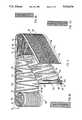
- FIG. 1illustrates a partially unwound filter element 10 formed of a coiled filter strip 12.
- the filter strip 12comprises a relatively thin strip of material, typically a flexible plastic having two different patterns formed thereon.
- a relatively smooth background surface 16from which protrudes a spacer groove defining protrusion 18, typically in the form of a generally sinusoidal, undulating wave, which extends generally back and forth between first and second edges 20 and 22 of the surface.
- Spacer groove defining protrusion 18is preferably but not necessarily of uniform thickness and may be of any desired thickness, depending on the size of the particles to be filtered.
- an array 26 of filter grooveswhich extend generally transversely with respect to spacer groove defining protrusion 18, except at the points of inflection thereof, adjacent the first and second edges 20 and 22.
- the filter grooves of array 26are sized so as to provide precisely defined filtration down to particles of a given minimum size.
- Filter groove array 26is typically bordered adjacent both edges 20 and 22 by non-grooved raised portions 28 and 30 respectively, which correspond in thickness to the height of the peaks of the interstices between the grooves of array 26.
- a complete filter element employing a coiled filter strip of the type illustrated in FIG. 1will have upstream and downstream filter surfaces for inlet of a fluid such as water to be filtered and exit thereof, respectively, at either of its butt ends 32 and 34, defined respectively by edges 20 and 22.
- the filter strip 12 illustrated in FIG. 1is symmetrical with respect to edges 20 and 22 and thus it does not matter which butt end is coupled as the upstream filter surface.
- the filter strip 12may be modified in one of a wide variety of ways to render it non-symmetric.
- filter element 10when filter element 10 is ready for use, it is tightly wound together and may, if desired, be bonded together by any suitable technique, such as adhesive bonding or ultrasonic welding, such that the outer facing edge of protrusion 18 sealingly engages borders 28 and 30 where they are in facing relationship and also sealingly engages the peaks of the interstices between the grooves of array 26.
- any suitable techniquesuch as adhesive bonding or ultrasonic welding, such that the outer facing edge of protrusion 18 sealingly engages borders 28 and 30 where they are in facing relationship and also sealingly engages the peaks of the interstices between the grooves of array 26.
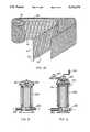
- FIG. 1BA sectional illustration of this engagement is provided in FIG. 1B.
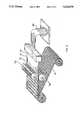
- FIG. 2illustrates an alternative embodiment of filter element 10, which is comprised of two filter strips 42 and 44 coiled together.
- Filter strip 42is typically formed of a porous material, such as polyester cartridge or polypropylene cartridge or any desired type of mesh and defines first and second edges 48 and 50.
- edge 48is located at the upstream end of the element 40, and that edge 50 is located at the downstream end of the element.
- the filter strip 42may be formed of porous material of any desired characteristics and pass through specifications and that the term, "porous material" as used herein, also includes screen material of any suitable mesh size. It also includes single or multiple layer porous material with uniform or different pass through characteristics.
- Filter strip 44typically defines a spacer strip having spacer groove patterns formed on opposite surfaces 52 and 54 thereof and respective edges 58 and 60. On surface 52, there is defined a groove pattern defining debris collecting grooves 56 communicating with edge 58, while on surface 54 there are defined generally back-to-back with grooves 56, exit grooves 62, communicating with edge 60.
- Grooves 56are defined by raised portions 64 which include a raised border 65 adjacent edge 60, while grooves 62 are defined by raised portions 66, which include a raised border 67 adjacent edge 58.
- the raised portions 64 and 66can be somewhat skewed with respect to each other as illustrated in FIG. 2B, such that raised portion 64 will diagonally overlie raised portion 66. This arrangement enables the planar portion of surfaces 52 and 54 to be made very thin.
- filter element 40when filter element 40 is ready for use, it is tightly wound together and may, if desired, be bonded together by any suitable technique, such as adhesive bonding or ultrasonic welding, such that the inner facing edge 68 of porous filter strip 42 sealingly engages raised portions 64 and border 65 of spacer strip 44 to define debris collection chambers. Similarly, it is preferred but not essential, that outer facing surface 69 of porous filter strip 42 sealingly engage raised portions 66 and border 67 of spacer strip 44. A sectional illustration of this engagement is provided in FIG. 2C.
- FIG. 3illustrates yet another configuration of filter element constructed and operative in accordance with a preferred embodiment of the present invention and which has similarities to both of the embodiments described hereinabove.
- the embodiment of FIG. 3comprises two filter strips 70 and 72 which are coiled together to define a filter element 74.
- Filter strip 70is typically formed with identical first and second side surfaces 76 and 78, each of which is formed with a generally longitudinally extending groove array 80, which may be similar in all relevant respects to groove array 26 described in connection with the embodiment of FIG. 1, hereinabove, and which is bordered along respective first and second edges 82 and 84 by raised border portions 86 and 88 respectively.
- Filter strip 72is typically formed with identical first and second side surfaces 90 and 92, each of which is formed with a relatively smooth background surface 96 from which protrudes a spacer groove defining protrusion 98, typically in the form of a generally sinusoidal, undulating wave, which extends generally back and forth between first and second edges 100 and 102 of the surface.
- Spacer groove defining protrusions 98are preferably but not necessarily of uniform thickness and may be of any desired thickness depending on the size of the particles to be filtered.
- a complete filter element employing a coiled filter strip of the type illustrated in FIG. 3will have upstream and downstream filter surfaces for inlet of a fluid such as water to be filtered and exit thereof, respectively, at either of its butt ends 130 and 132.
- the filter element 74is symmetrical with respect to ends 130 and 132 and thus it does not matter which butt end is coupled as the upstream filter surface.
- the filter strip 72may be modified in one of a wide variety of ways to render it non-symmetric.
- filter element 74When filter element 74 is ready for use, it is tightly wound together and may, if desired, be bonded together by any suitable technique, such as adhesive bonding or ultrasonic welding, such that the outer facing edge of protrusion 98 sealingly engages borders 86 and 88 where they are in facing relationship and also sealingly engages the peaks of the interstices between the grooves of array 80. A sectional illustration of this engagement is provided in FIG. 3B.
- FIG. 4illustrates apparatus for producing a filter strip of the type illustrated in FIG. 1.
- a strip extruder 150receives a supply of a thermoplastic material such as polyethylene or polypropylene or any similar desired material and produces a strip of such material. While the strip is still hot and formable, it passes between a pair of embossing rollers 152 and 154, which respectively form thereon the patterns formed on respective surfaces 24 and 14 of strip 12 (FIG. 1). The strip is then coiled to form the filter element 10. If coiled while still in a plastic state, simple tight coiling may be sufficient to hold the coil sufficiently tightly together such that it is effectively heat welded without requiring any additional heat welding step.
- a thermoplastic materialsuch as polyethylene or polypropylene or any similar desired material
- FIG. 5illustrates the corresponding production of the filter element of FIG. 2, it being noted that the porous strip 42 is not embossed but the spacer strip 44 is embossed on both sides by rollers 156 and 158 with the respective patterns which appear on surfaces 52 and 54 thereof.
- the extrusion apparatus 160may be identical to that employed in the embodiment shown in FIG. 4.
- FIG. 6illustrates the production of the filter element of FIG. 3.
- the strip 70is produced by an extruder 170 and embossing rollers 172 and 173, while the strip 72 is produced by an extruder 174 and embossing rollers 176 and 178.
- the two embossed stripsare then rolled together to define filter element 74.
- FIG. 7illustrates an alternative embodiment of the invention, wherein a first filter strip 180 having formed thereon an embossed pattern of, possibly but not necessarily skewed, spacer protrusions 182 of the type typically illustrated in FIG. 1, and having formed on the spacer protrusions transverse filter grooves 184, is heat welded by conventional welding rollers 186 and 188 to a smooth strip 190 thus producing a filter strip 192 having the cross sectional configuration illustrated in FIG. 7.
- Filter strip 192will be used similarly to the type illustrated in FIG. 1, to form filter element 10, it being noted that filter strip 180 is embossed on one side only so that both outer surfaces of the filter strip 192 will be smooth.
- FIG. 8illustrates apparatus for extruding a generally cylindrical covering over a coiled filter element of the type described hereinabove.
- the apparatus of FIG. 8includes coil feeding means 200, including a storage rack 210 and a pusher arm 212, which may be operated by a piston 214, which automatically inserts coiled filter strips 216 of the type described hereinabove into an angled extrusion head of a conventional extruder.
- the extruded productis effectively a continuous extruded tube, having disposed therein at spaced intervals, coiled filter elements 216.
- the thus coated and sealed coiled filter elementsare then trimmed by trimming apparatus 218 and are ready for further processing.
- FIG. 9Aillustrates a coated coiled filter element such as could be produced by the apparatus of FIG. 8 with coupling ends 220 and 220 which may be used for attachment of the filter element to supply and drain connections.
- FIG. 9Bshows an alternative arrangment of coated coiled filter element with butt ends 260 and 280 which may be attached to connectors 262 and 282 intermediate the filter element and a supply or drain connection.
- FIG. 9Cshows a coated coiled filter element which is essentially similar to that of FIG. 9B, but held inside a housing 290 by sealing rings 292 which are so positioned as to seal the inlet and the outlet.
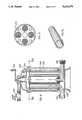
- FIGS. 10, 11 and 12illustrate a backwashable filter constructed and operative in accordance with a preferred embodiment of the present invention and comprising a housing 230 defining a water inlet 232 communicating with a top manifold 234 and a filtered water outlet 236 communicating with a bottom manifold 238.
- a plurality of coiled filter elements 240 of the type described hereinaboveare located within the housing 230 with a first end thereof in water receiving communication with the inlet top manifold 234 and a second end thereof in filtered water providing relationship with the bottom manifold 238.
- Vacuum element 244as it scans each coiled filter element at its upstream end, sucks up the particles accumulated therein.
- FIG. 13illustrates an alternative filter construction including a housing 250 and a water inlet 252 which communicates with a fluid flow path 254 formed at the center of a coiled filter element 256.
- the fluid flow path 254can conveniently be formed by coiling filter strips around a hollow tube, using essentially the same production techniques as described hereinabove.
- Water exiting from path 254enters the filter element at an upstream end 256 and exits therefrom from a downstream end 258.
- FIG. 14describes a backflushable filter of the type illustrated in FIG. 13. Backflushing is provided by opening the draining valve 262 and by manual rotation of vacuum element 264 by means of handle 266. Vacuum element 264 scans the filter element at its upstream end and sucks up the particles accumulated therein.
Landscapes
- Chemical & Material Sciences (AREA)
- Chemical Kinetics & Catalysis (AREA)
- Filtering Materials (AREA)
Abstract
Description
This is a continuation of application Ser. No. 07/567,638 filed Aug. 15, 1990, now U.S. Pat. No. 5,174,895, itself a continuation of application Ser. No. 07/297,496 filed Jan. 17, 1989, now U.S. Pat. No. 5,015,379.
The present invention relates to fluid filter apparatus generally and more particularly to backflushable filters for liquids, such as water.
Various types of backflushable filters are known. A particularly useful type of such filters is the disk filter, which is comprised of a stack of filter disks. Disk filters are described and claimed in applicant's U.S. Pat. No. 4,683,060.
The present invention seeks to provide a new type of backflushable filter which is highly efficient, easy to clean, and relatively inexpensive to manufacture, and which provides, in a small physical area, a large filter surface area.
There is thus provided in accordance with a preferred embodiment of the present invention a filter element comprising at least one coiled filter strip defining first and second butt ends, one of the butt ends being arranged to define an upstream surface during normal filtering operation, receiving fluid to be filtered, and the other of the butt ends being arranged to define a downstream surface during normal filtering operation, through which filtered fluid leaves the coiled strip.
Additionally in accordance with an embodiment of the invention the filter strip is formed to have one surface defining an array of longitudinally extending filter grooves extending along the longitudinal axis of the filter strip and to have an opposite surface defining a spacer groove which engages filter grooves, when the filter strip is coiled, to define a filtration pathway of predetermined cross section and collection regions for particles which do not pass through the filtration pathway.
According to an alternative embodiment of the invention, the filter element is formed of at least two filter strips coiled together. Preferably, the at least two filter strips comprise a filtering strip and a spacer strip. The filtering strip may comprise a grooved strip or, preferably a porous strip.
Additionally in accordance with an embodiment of the present invention, the coiled filter strip or strips are held closely together by being coiled. Alternatively, the coil or the strips may be held in a tight condition by the use of adhesive or by welding, such as ultrasonic welding.
According to one embodiment of the invention, the coiled filter strip or strips may be coiled about a hollow tube.
Further in accordance with a preferred embodiment of the present invention, there is provided a backflushable filter comprising at least one filter element of the type described above and apparatus for supplying fluid to be filtered to a first end of the filter element defining an upstream filter element surface and for receiving filtered fluid from the opposite end thereof defining a downstream filter element surface.
Additionally in accordance with an embodiment of the invention, there is also provided means for supplying backflushing fluid to the downstream filter element surface and means for removing the fluid received from the upstream filter element surface.
Further in accordance with an embodiment of the invention, the means for removing includes means for vacuum scanning of the upstream filter element surface.
Still further in accordance with an embodiment of the present invention, there is provided a technique for manufacture of filter elements comprising the steps of extruding at least one filter strip, embossing the at least one filter strip with a groove pattern, and coiling the at least one filter strip.
Further in accordance with this embodiment of the invention, there is also provided the step of extruding over the coiled filter a cylindrical cover.
Additionally in accordance with an embodiment of the invention, following the step of extruding the cover, end caps, defining fluid inlets or outlets are fitted in sealing engagement over the coiled filter.
Further in accordance with an embodiment of the invention, there is also provided a step of securing the coiled filter strip in tight engagement which comprises the step of bonding, which may be achieved by means of adhesive or welding, such as ultrasonic welding.
The present invention will be understood and appreciated more fully from the following detailed description taken in conjunction with the drawings in which:
FIG. 1 illustrates a single filter strip in partially coiled orientation;
FIG. 1B shows a sectional illustration of the single filter strip of FIG. 1 in coiled orientation;
FIG. 2 illustrates a pair of filter strips in partially coiled orientation in accordance with one embodiment of the invention;
FIG. 2B illustrates a pair of filter strips in partially coiled orientation according to an alternative embodiment of the present invention;
FIG. 2C shows a sectional illustration of the pair of filter strips of FIG. 2 taken along lines C--C, in coiled orientation;
FIG. 3 illustrates a pair of filter strips in partially coiled orientation in accordance with another embodiment of the invention;
FIG. 3B shows a sectional illustration of the pair of filter strips of FIG. 3 in coiled orientation;
FIG. 4 illustrates a technique for producing a coiled filter strip of the type shown in FIG. 1;
FIG. 5 illustrates a technique for producing coiled filter strips of the type shown in FIG. 2;
FIGS. 6A and 6B illustrate a technique for producing coiled filter strips of the type shown in FIG. 3;
FIG. 7 illustrates a technique for producing coiled filter strips according to an alternative embodiment of the present invention;
FIG. 7B shows a sectional illustration of the coiled filter strips produced by the technique of FIG. 7;
FIG. 8 illustrates an extrusion technique for enclosing coiled filter strips;
FIGS. 9A, 9B and 9C, illustrate three alternative embodiments of coiled, enclosed filter strips;
FIG. 10 is a side view interior illustration of a backflushable filter constructed and operative in accordance with a preferred embodiment of the present invention and employing filter elements formed of coiled filter strips;
FIG. 11 is a sectional illustration taken along the lines XI--XI of FIG. 10;
FIG. 12 is a pictorial illustration of a detail of the backflushing apparatus taken along the lines XII--XII of FIG. 10;
FIGS. 13 and 14 are side view interior illustrations of two alternative types of filters employing a filter element formed of a coiled filter strip having a central flowthrough passage formed therein.
Reference is now made to FIG. 1, which illustrates a partiallyunwound filter element 10 formed of a coiledfilter strip 12. In this embodiment of the invention, thefilter strip 12 comprises a relatively thin strip of material, typically a flexible plastic having two different patterns formed thereon. On afirst surface 14 there is typically provided a relativelysmooth background surface 16 from which protrudes a spacergroove defining protrusion 18, typically in the form of a generally sinusoidal, undulating wave, which extends generally back and forth between first andsecond edges 20 and 22 of the surface.
Spacergroove defining protrusion 18 is preferably but not necessarily of uniform thickness and may be of any desired thickness, depending on the size of the particles to be filtered.
On a second,opposite surface 24 ofstrip 12, there is formed anarray 26 of filter grooves, which extend generally transversely with respect to spacergroove defining protrusion 18, except at the points of inflection thereof, adjacent the first andsecond edges 20 and 22. The filter grooves ofarray 26 are sized so as to provide precisely defined filtration down to particles of a given minimum size.
It will be appreciated that a complete filter element employing a coiled filter strip of the type illustrated in FIG. 1, will have upstream and downstream filter surfaces for inlet of a fluid such as water to be filtered and exit thereof, respectively, at either of its butt ends 32 and 34, defined respectively byedges 20 and 22. Thefilter strip 12 illustrated in FIG. 1 is symmetrical with respect toedges 20 and 22 and thus it does not matter which butt end is coupled as the upstream filter surface. Alternatively, thefilter strip 12 may be modified in one of a wide variety of ways to render it non-symmetric.
One possible modification would be to make the spacer grooves defined byprotrusion 18 and facing edge 20 of larger area than those spacergrooves facing edge 22. Other modifications are also possible.
It is noted that whenfilter element 10 is ready for use, it is tightly wound together and may, if desired, be bonded together by any suitable technique, such as adhesive bonding or ultrasonic welding, such that the outer facing edge ofprotrusion 18 sealingly engagesborders array 26. A sectional illustration of this engagement is provided in FIG. 1B.
Assuming, for the purposes of discussion that the upstream end of thefilter element 10 is atend 32, it is appreciated that fluid, such as water to be filtered, enters the filter atend 32 and passes throughdirt accumulation grooves 36 which are defined byprotrusion 18 and communicate with theupstream end 32 and then passes through the cross-sectional areas of the filter grooves ofarray 26, past the juxtaposed portion of facingprotrusion 18, as illustrated in FIG. 1B. The thus filtered fluid, then passes throughexit grooves 37 as it exits viadownstream end 34.
Reference is now made to FIG. 2 which illustrates an alternative embodiment offilter element 10, which is comprised of twofilter strips Filter strip 42 is typically formed of a porous material, such as polyester cartridge or polypropylene cartridge or any desired type of mesh and defines first andsecond edges edge 48 is located at the upstream end of theelement 40, and thatedge 50 is located at the downstream end of the element. It is specifically noted that thefilter strip 42 may be formed of porous material of any desired characteristics and pass through specifications and that the term, "porous material" as used herein, also includes screen material of any suitable mesh size. It also includes single or multiple layer porous material with uniform or different pass through characteristics.
In order to provide maximum structural strength tospacer strip 44, the raisedportions portion 64 will diagonally overlie raisedportion 66. This arrangement enables the planar portion ofsurfaces
It is noted that whenfilter element 40 is ready for use, it is tightly wound together and may, if desired, be bonded together by any suitable technique, such as adhesive bonding or ultrasonic welding, such that the inner facingedge 68 ofporous filter strip 42 sealingly engages raisedportions 64 andborder 65 ofspacer strip 44 to define debris collection chambers. Similarly, it is preferred but not essential, that outer facingsurface 69 ofporous filter strip 42 sealingly engage raisedportions 66 andborder 67 ofspacer strip 44. A sectional illustration of this engagement is provided in FIG. 2C.
Reference is now made to FIG. 3 which illustrates yet another configuration of filter element constructed and operative in accordance with a preferred embodiment of the present invention and which has similarities to both of the embodiments described hereinabove. The embodiment of FIG. 3 comprises twofilter strips filter element 74.
Spacer groove defining protrusions 98 are preferably but not necessarily of uniform thickness and may be of any desired thickness depending on the size of the particles to be filtered.
It will be appreciated that a complete filter element employing a coiled filter strip of the type illustrated in FIG. 3, will have upstream and downstream filter surfaces for inlet of a fluid such as water to be filtered and exit thereof, respectively, at either of its butt ends 130 and 132.
Thefilter element 74 is symmetrical with respect to ends 130 and 132 and thus it does not matter which butt end is coupled as the upstream filter surface. Alternatively, thefilter strip 72 may be modified in one of a wide variety of ways to render it non-symmetric.
One possible modification would be to make the spacer grooves defined by protrusion 98 and facingedge 100 of larger area than those spacergrooves facing edge 102. Other modifications are also possible.
Whenfilter element 74 is ready for use, it is tightly wound together and may, if desired, be bonded together by any suitable technique, such as adhesive bonding or ultrasonic welding, such that the outer facing edge of protrusion 98 sealingly engagesborders 86 and 88 where they are in facing relationship and also sealingly engages the peaks of the interstices between the grooves ofarray 80. A sectional illustration of this engagement is provided in FIG. 3B.
Assuming, for the purposes of discussion, that the upstream end of thefilter element 74 is atend 132, it is appreciated that fluid, such as water to be filtered, enters the filter atend 132 and passes throughdirt accumulation grooves 136 which are defined by protrusion 98 and communicate with theupstream end 132 and then pass through the cross-sectional areas of the filter grooves ofarray 80, past the juxtaposed portion of facing protrusion 98, as illustrated in FIG. 3B. The thus filtered fluid, then passes throughexit grooves 137 as it exits viadownstream end 130.
Reference is now made to FIG. 4 which illustrates apparatus for producing a filter strip of the type illustrated in FIG. 1. Astrip extruder 150, receives a supply of a thermoplastic material such as polyethylene or polypropylene or any similar desired material and produces a strip of such material. While the strip is still hot and formable, it passes between a pair ofembossing rollers respective surfaces filter element 10. If coiled while still in a plastic state, simple tight coiling may be sufficient to hold the coil sufficiently tightly together such that it is effectively heat welded without requiring any additional heat welding step.
FIG. 5 illustrates the corresponding production of the filter element of FIG. 2, it being noted that theporous strip 42 is not embossed but thespacer strip 44 is embossed on both sides byrollers surfaces extrusion apparatus 160 may be identical to that employed in the embodiment shown in FIG. 4.
FIG. 6 illustrates the production of the filter element of FIG. 3. Thestrip 70 is produced by anextruder 170 andembossing rollers strip 72 is produced by anextruder 174 andembossing rollers filter element 74.
FIG. 7 illustrates an alternative embodiment of the invention, wherein afirst filter strip 180 having formed thereon an embossed pattern of, possibly but not necessarily skewed,spacer protrusions 182 of the type typically illustrated in FIG. 1, and having formed on the spacer protrusionstransverse filter grooves 184, is heat welded byconventional welding rollers smooth strip 190 thus producing afilter strip 192 having the cross sectional configuration illustrated in FIG. 7.Filter strip 192 will be used similarly to the type illustrated in FIG. 1, to formfilter element 10, it being noted thatfilter strip 180 is embossed on one side only so that both outer surfaces of thefilter strip 192 will be smooth.
Reference is not made to FIG. 8, which illustrates apparatus for extruding a generally cylindrical covering over a coiled filter element of the type described hereinabove. The apparatus of FIG. 8 includes coil feeding means 200, including astorage rack 210 and apusher arm 212, which may be operated by apiston 214, which automatically inserts coiled filter strips 216 of the type described hereinabove into an angled extrusion head of a conventional extruder. The extruded product is effectively a continuous extruded tube, having disposed therein at spaced intervals,coiled filter elements 216.
The thus coated and sealed coiled filter elements are then trimmed by trimmingapparatus 218 and are ready for further processing.
FIG. 9A illustrates a coated coiled filter element such as could be produced by the apparatus of FIG. 8 with coupling ends 220 and 220 which may be used for attachment of the filter element to supply and drain connections.
FIG. 9B shows an alternative arrangment of coated coiled filter element with butt ends 260 and 280 which may be attached toconnectors
FIG. 9C shows a coated coiled filter element which is essentially similar to that of FIG. 9B, but held inside ahousing 290 by sealing rings 292 which are so positioned as to seal the inlet and the outlet.
FIGS. 10, 11 and 12 illustrate a backwashable filter constructed and operative in accordance with a preferred embodiment of the present invention and comprising ahousing 230 defining awater inlet 232 communicating with atop manifold 234 and a filteredwater outlet 236 communicating with abottom manifold 238.
A plurality of coiledfilter elements 240 of the type described hereinabove are located within thehousing 230 with a first end thereof in water receiving communication with the inlettop manifold 234 and a second end thereof in filtered water providing relationship with thebottom manifold 238.
Backflushing is provided by opening the drainingvalve 242 and by manual rotation ofvacuum element 244 by means ofhandle 246.Vacuum element 244 as it scans each coiled filter element at its upstream end, sucks up the particles accumulated therein.
FIG. 13 illustrates an alternative filter construction including ahousing 250 and awater inlet 252 which communicates with afluid flow path 254 formed at the center of acoiled filter element 256. Thefluid flow path 254 can conveniently be formed by coiling filter strips around a hollow tube, using essentially the same production techniques as described hereinabove.
Water exiting frompath 254 enters the filter element at anupstream end 256 and exits therefrom from adownstream end 258.
FIG. 14 describes a backflushable filter of the type illustrated in FIG. 13. Backflushing is provided by opening the drainingvalve 262 and by manual rotation ofvacuum element 264 by means ofhandle 266.Vacuum element 264 scans the filter element at its upstream end and sucks up the particles accumulated therein.
It will be appreciated by persons skilled in the art that the present invention is not limited to what has been particularly shown and described hereinbelow. Rather the scope of the present invention will be defined only by the claims which follow:
Claims (21)
1. A filter element, comprising:
at least one filter strip having first and second lengthwise-extending edges, said at least one filter strip being rolled in close engagement to form a coil having a longitudinal axis, the first and second edges of said coiled at least one filter strip forming first and second ends of said coil, one of the ends of said coil defining the inlet end of said coil and the inlet edge of said filter strip during filtering operation, receiving fluid to be filtered, and the other of the ends of said coil defining the outlet end of said coil and the outlet edge of said at least one filter strip during filtering operation, through which filtered fluid leaves the coil strip;
said at least one filter strip having at least a first and a second surface, said first surface having a continuous protrusion of generally undulating configuration and said second surface being substantially free of protrusions, such that when said at least one filter strip is coiled, said first and second surfaces are brought together in close engagement and define therebetween upstream and downstream extending chambers separated by said protrusions, said upstream extending chambers opening at the inlet end of said coil and said downstream extending chambers opening at the outlet end of said coil,
the ridge of said protrusion on said first surface and the face of said second surface being configured such that when in contact with one another, filter pathways of predetermined size are created extending between said upstream and downstream extending chambers for fluid flow from the upstream chambers to the downstream chambers and for accumulation of particles of larger size than said pathways in said upstream extending chambers during filtering operation.
2. A filter element in accordance with claim 1, further including a generally cylindrical sleeve covering the outer perimeter of said coil in close engagement therewith.
3. A filter element in accordance with claim 1, wherein said at least one filter strip consists of a single filter strip, said first surface being one side of said single filter strip and said second surface being the other side of said single filter strip.
4. A filter element in accordance with claim 1, wherein said at least one filter strip consists of two filter strips, both sides of one of said filter strips having a continuous protrusion of generally undulating configuration and both sides of the other of said filter strips being substantially free of protrusions, whereby, when coiled, a surface with protrusions is always in contact with a surface without protrusions, said contacting surfaces being said first and second surfaces of said at least one filter strip.
5. A filter element in accordance with claim 1, wherein said second surface has an array of continuous lengthwise-extending grooves therein, said grooves forming said filter pathways when in close engagement with the ridges of the protrusion of said first surface.
6. A filter element in accordance with claim 1, wherein the ridge of said protrusion of said first surface has a plurality of grooves therein, said grooves forming said filter pathways when said protrusion is in close engagement with said second surface.
7. A filter element in accordance with claim 6, wherein said second surface is substantially smooth.
8. A filter element in accordance with claim 3, wherein said second surface has an array of continuous lengthwise-extending grooves therein, said grooves forming said filter pathways when in close engagement with the ridges of the protrusion of said first surface.
9. A filter element in accordance with claim 3, wherein the ridge of said protrusion of said first surface has a plurality of grooves therein, said grooves forming said filter pathways when said protrusion is in close engagement with said second surface.
10. A filter element in accordance with claim 4, wherein said second surface has an array of continuous lengthwise-extending grooves therein, said grooves forming said filter pathways when in close engagement with the ridges of the protrusion of said first surface.
11. A filter element in accordance with claim 4, wherein the ridge of said protrusion of said first surface has a plurality of grooves therein, said grooves forming said filter pathways when said protrusion is in close engagement with said second surface.
12. A filter element in accordance with claim 1, wherein said first and second surfaces are bonded together.
13. A filter element in accordance with claim 12, wherein said first and second surfaces are welded together.
14. A filter element in accordance with claim 12, wherein said first and second surfaces are glued together.
15. A filter element, comprising:
at least two filter strips, each having first and second lengthwise-extending edges, said at least two filter strips being coiled in close engagement to form a coil having a longitudinal axis, the first and second edges of said coiled filter strips forming first and second ends of said coil, one of the ends of said coil defining the inlet end of said coil and the inlet edge of said filter strips during filtering operation, receiving fluid to be filtered, and the other of the ends of said coil defining the outlet end of said coil and the outlet edge of said filter strips during filtering operation, through which filtered fluid leaves the coiled strip;
said at least two filter strips including a first filter strip, formed from porous material, and a second filter strip, said second filter strip having first and second surfaces each of said first and second surfaces having raised portions defining filter grooves, each said groove being surrounded on all lengthwise and axial direction sides by said raised portions, except for one opening in the axial direction, such that when the first and second surfaces of said second filter strip are in close engagement with a first porous filter strip, said filter grooves form elongated chambers, and wherein the chambers which open at the inlet edge of said strip and are defined as upstream chambers and the chambers which open at the outlet edge of said strips and are defined as downstream chambers, said first porous filter strip being disposed adjacent said second filter strip such that when coiled, said first porous filter strip is disposed between said upstream chambers and said downstream chambers to thereby form porous pathways between said upstream and downstream chambers for fluid flow from the upstream chambers to the downstream chambers and for accumulation of particles of larger size than said pathways in said upstream chambers during filtering operation.
16. A filter element in accordance with claim 15, wherein said first surface of said second filter strip contains only upstream chambers and said second surface of said second filter strip contains only downstream chambers, said first porous filter strip being disposed between said upstream chambers of the first surface of a second filter strip and said downstream chambers of the second surface of a second filter strip.
17. A filter element in accordance with claim 16, wherein said upstream chambers are inclined at an angle with respect to said downstream chambers such that each said upstream chamber will communicate, through said porous filter strip, with a plurality of said downstream chambers.
18. A filter element in accordance with claim 15, further including a generally cylindrical sleeve covering the outer perimeter of said coil in close engagement therewith.
19. A filter element in accordance with claim 15, wherein said first and second filter strips are bonded together.
20. A filter element in accordance with claim 18, wherein said first and second surfaces are welded together.
21. A filter element in accordance with claim 18, wherein said first and second filter strips are glued together.
Priority Applications (1)
| Application Number | Priority Date | Filing Date | Title |
|---|---|---|---|
| US07/997,172US5316676A (en) | 1988-03-16 | 1992-12-28 | Coiled filter strip with upstream and downstream butt ends |
Applications Claiming Priority (5)
| Application Number | Priority Date | Filing Date | Title |
|---|---|---|---|
| IL85762AIL85762A0 (en) | 1988-03-16 | 1988-03-16 | Back-flushable filter |
| IL85762 | 1988-03-16 | ||
| US07/297,496US5015379A (en) | 1988-03-16 | 1989-01-17 | Coiled filter strip with upstream and downstream butt ends |
| US07/567,638US5174895A (en) | 1988-03-16 | 1990-08-15 | Coiled filter strip with upstream and downstream butt ends |
| US07/997,172US5316676A (en) | 1988-03-16 | 1992-12-28 | Coiled filter strip with upstream and downstream butt ends |
Related Parent Applications (1)
| Application Number | Title | Priority Date | Filing Date |
|---|---|---|---|
| US07/567,638ContinuationUS5174895A (en) | 1988-03-16 | 1990-08-15 | Coiled filter strip with upstream and downstream butt ends |
Publications (1)
| Publication Number | Publication Date |
|---|---|
| US5316676Atrue US5316676A (en) | 1994-05-31 |
Family
ID=26321781
Family Applications (2)
| Application Number | Title | Priority Date | Filing Date |
|---|---|---|---|
| US07/297,496Expired - Fee RelatedUS5015379A (en) | 1988-03-16 | 1989-01-17 | Coiled filter strip with upstream and downstream butt ends |
| US07/997,172Expired - Fee RelatedUS5316676A (en) | 1988-03-16 | 1992-12-28 | Coiled filter strip with upstream and downstream butt ends |
Family Applications Before (1)
| Application Number | Title | Priority Date | Filing Date |
|---|---|---|---|
| US07/297,496Expired - Fee RelatedUS5015379A (en) | 1988-03-16 | 1989-01-17 | Coiled filter strip with upstream and downstream butt ends |
Country Status (1)
| Country | Link |
|---|---|
| US (2) | US5015379A (en) |
Cited By (42)
| Publication number | Priority date | Publication date | Assignee | Title |
|---|---|---|---|---|
| USD366040S (en) | 1993-10-25 | 1996-01-09 | Environmental Procedures, Inc. | Screen |
| US5820646A (en)* | 1996-04-26 | 1998-10-13 | Donaldson Company, Inc. | Inline filter apparatus |
| US5871641A (en)* | 1996-05-30 | 1999-02-16 | H-Tech, Inc. | Fluid filter with pleated septum |
| US5882528A (en)* | 1995-05-31 | 1999-03-16 | H-Tech, Inc. | Method for extending useful life of filter aid in a filter with hydraulically deformable system |
| US5885453A (en)* | 1995-06-22 | 1999-03-23 | Institut Textile De France And Bio Merieux | Device for the physicochemical separation of constituents of a fluid |
| US5895574A (en)* | 1996-04-26 | 1999-04-20 | Donaldson Company, Inc. | Rolled liquid filter using fluted media |
| US5902364A (en)* | 1996-04-26 | 1999-05-11 | Donaldson Company, Inc. | Conical filter |
| US6379437B1 (en) | 1997-09-19 | 2002-04-30 | Valtion Teknillinen Tutkimuskeskus | Filter for gases |
| US6450345B1 (en) | 1993-04-30 | 2002-09-17 | Varco I/P, Inc. | Glue pattern screens and methods of production |
| US20030010437A1 (en)* | 1998-10-30 | 2003-01-16 | Adams Thomas C. | Screens for vibratory separators |
| US6565698B1 (en) | 1993-04-30 | 2003-05-20 | Varco I/P, Inc. | Method for making vibratory separator screens |
| US6669985B2 (en) | 1998-10-30 | 2003-12-30 | Varco I/P, Inc. | Methods for making glued shale shaker screens |
| US20040007508A1 (en)* | 1999-12-04 | 2004-01-15 | Schulte David L. | Screen assembly for vibratory separator |
| US6736270B2 (en) | 1998-10-30 | 2004-05-18 | Varco I/P, Inc. | Glued screens for shale shakers |
| US20040251175A1 (en)* | 1998-10-30 | 2004-12-16 | Adams Thomas C. | Apparatuses and methods for making glued screen assemblies |
| US20050252182A1 (en)* | 2001-12-03 | 2005-11-17 | Donaldson Company | Filter element using corrugated media sheet |
| US6997969B1 (en)* | 2003-07-17 | 2006-02-14 | Lpd Technologies | Filter material and method |
| WO2006042079A1 (en)* | 2004-10-06 | 2006-04-20 | State Of Oregon Acting By And Through The State Board Of Higher Education On Behalf Of Oregon State University | Mecs dialyzer |
| US20060163150A1 (en)* | 2002-07-10 | 2006-07-27 | Dondaldson Company, Inc. | Fluted filter medium and process for its manufacture |
| US20080000826A1 (en)* | 2006-06-12 | 2008-01-03 | Harder David B | Rolled axial flow filter and methods |
| US7329326B2 (en) | 1996-04-26 | 2008-02-12 | Donaldson Company, Inc. | Method of making a fluted filter media for air filter |
| USD584390S1 (en)* | 2006-05-11 | 2009-01-06 | Acs Industries, Inc. | Wound wire filter |
| US20090127185A1 (en)* | 2007-11-21 | 2009-05-21 | Ibs Filtran Kunststoff-/Metallerzeugnisse Gmbh | Filter element |
| US20090211977A1 (en)* | 2008-02-27 | 2009-08-27 | Oregon State University | Through-plate microchannel transfer devices |
| US20090311420A1 (en)* | 2005-01-03 | 2009-12-17 | Mark Drlik | Method for making parallel passage contactors |
| US20100032365A1 (en)* | 2008-08-06 | 2010-02-11 | Ted Anthony Moe | Z-media having flute closures, methods and apparatus |
| US20100064644A1 (en)* | 2008-09-18 | 2010-03-18 | Yuqing Ding | Laminate filter |
| US20100326916A1 (en)* | 2009-06-24 | 2010-12-30 | State of Oregon acting by and through the State Board of Higher Education on behalf of Oregon | Dialysis system |
| US20100326914A1 (en)* | 2009-06-24 | 2010-12-30 | State of Oregon acting by and through the State Board of Higher Education on behalf of Oregon | Microfluidic devices |
| US7955504B1 (en) | 2004-10-06 | 2011-06-07 | State Of Oregon Acting By And Through The State Board Of Higher Education On Behalf Of Oregon State University | Microfluidic devices, particularly filtration devices comprising polymeric membranes, and method for their manufacture and use |
| US20110189048A1 (en)* | 2009-12-05 | 2011-08-04 | Curtis James R | Modular dialysis system |
| US20120272831A1 (en)* | 2007-08-06 | 2012-11-01 | Janet Barberio | Wine pouring regulator and aerator therein |
| US8501009B2 (en) | 2010-06-07 | 2013-08-06 | State Of Oregon Acting By And Through The State Board Of Higher Education On Behalf Of Oregon State University | Fluid purification system |
| US8580161B2 (en) | 2010-05-04 | 2013-11-12 | State Of Oregon Acting By And Through The State Board Of Higher Education On Behalf Of Oregon State University | Fluidic devices comprising photocontrollable units |
| US8911606B1 (en) | 2007-05-31 | 2014-12-16 | Sandia Corporation | Dielectrokinetic chromatography devices |
| US9328969B2 (en) | 2011-10-07 | 2016-05-03 | Outset Medical, Inc. | Heat exchange fluid purification for dialysis system |
| US9402945B2 (en) | 2014-04-29 | 2016-08-02 | Outset Medical, Inc. | Dialysis system and methods |
| US9545469B2 (en) | 2009-12-05 | 2017-01-17 | Outset Medical, Inc. | Dialysis system with ultrafiltration control |
| WO2017009352A1 (en)* | 2015-07-16 | 2017-01-19 | Eaton Technology Ip Gmbh & Co. Kg | Wound filter module |
| US11534537B2 (en) | 2016-08-19 | 2022-12-27 | Outset Medical, Inc. | Peritoneal dialysis system and methods |
| US12201762B2 (en) | 2018-08-23 | 2025-01-21 | Outset Medical, Inc. | Dialysis system and methods |
| US12390565B2 (en) | 2019-04-30 | 2025-08-19 | Outset Medical, Inc. | Dialysis systems and methods |
Families Citing this family (12)
| Publication number | Priority date | Publication date | Assignee | Title |
|---|---|---|---|---|
| DE3803693A1 (en)* | 1987-03-10 | 1988-09-22 | Akzo Gmbh | MULTI-LAYER HOLLOW FILM BODY |
| US5762868A (en)* | 1995-11-30 | 1998-06-09 | Minnesota Mining And Manufacturing Company | Blood oxygenator and heat exchanger |
| JP3902232B2 (en)* | 1995-11-30 | 2007-04-04 | テルモ カーディオバスキュラー システムズコーポレイション | Multilayer hollow fiber body and method for producing the same |
| WO1998052674A1 (en)* | 1996-04-26 | 1998-11-26 | Maeda Limited | Filter for compressed air |
| US20030006186A1 (en)* | 1998-10-05 | 2003-01-09 | Pulek John L. | Spiral wound depth filter |
| EP1117468B1 (en) | 1998-10-05 | 2003-03-19 | Cuno Incorporated | Filter and method of filtering a fluid |
| US7140495B2 (en)* | 2001-12-14 | 2006-11-28 | 3M Innovative Properties Company | Layered sheet construction for wastewater treatment |
| US7114621B2 (en)* | 2001-12-14 | 2006-10-03 | 3M Innovative Properties Company | Membrane module elements |
| US6986428B2 (en)* | 2003-05-14 | 2006-01-17 | 3M Innovative Properties Company | Fluid separation membrane module |
| JP4855119B2 (en) | 2006-03-28 | 2012-01-18 | テルモ株式会社 | Filter member and artificial lung |
| US7967980B2 (en)* | 2006-11-17 | 2011-06-28 | Kobelco Construction Machinery Co., Ltd. | Construction machine having working oil tank with filter case |
| USD844905S1 (en)* | 2016-12-05 | 2019-04-02 | Jenise A. Crossing | Bale feeder |
Citations (33)
| Publication number | Priority date | Publication date | Assignee | Title |
|---|---|---|---|---|
| GB189711750A (en)* | 1897-05-11 | 1897-06-12 | John Wotherspoon | Improvements in Apparatus for Filtering Feed-water for Steam Boilers. |
| US2125532A (en)* | 1936-01-22 | 1938-08-02 | Wells Herbert James Clement | Continuous flow strainer |
| US2372545A (en)* | 1942-11-27 | 1945-03-27 | Charles B Breedlove | Guard or baffle for fuel tanks |
| US2397759A (en)* | 1942-04-17 | 1946-04-02 | Sigmund Miroslav | Filter |
| GB588991A (en)* | 1943-04-03 | 1947-06-09 | Southwick Walbridge Briggs | Improved method of clarifying fluids |
| US2487769A (en)* | 1944-12-06 | 1949-11-08 | Olson Filtration Engineers Inc | Filter |
| US3037637A (en)* | 1960-04-26 | 1962-06-05 | Mine Safety Appliances Co | Spiral roll filter unit |
| US3042214A (en)* | 1958-12-16 | 1962-07-03 | Arvan Products Inc | Filter apparatus |
| US3055290A (en)* | 1960-05-19 | 1962-09-25 | Arvan Products Inc | Filter system |
| GB951404A (en)* | 1959-09-01 | 1964-03-04 | Pall Corp | Filter unit |
| US3212643A (en)* | 1962-08-31 | 1965-10-19 | Jr Henry Schmidt | Filtering apparatus |
| AU5236364A (en)* | 1965-11-30 | 1967-06-01 | Ts. G. Limited | Filter and water softener utilizing same |
| US3323963A (en)* | 1964-01-08 | 1967-06-06 | Mine Safety Appliances Co | Method of making filter coil |
| US3536200A (en)* | 1969-02-18 | 1970-10-27 | Du Pont | Filter assembly having tapered housing and inlet tube |
| DE2335214A1 (en)* | 1972-07-19 | 1974-01-31 | Georges Moatti | SELF-CLEANING FILTER |
| DE2629151A1 (en)* | 1975-07-28 | 1977-02-17 | Brunswick Corp | FILTER UNIT |
| US4039457A (en)* | 1973-02-02 | 1977-08-02 | Robert Bosch G.M.B.H. | Coiled filter element for filtering of liquids |
| US4059518A (en)* | 1975-07-29 | 1977-11-22 | Dover Corporation | Filter with axially shiftable rotating backwash selector |
| DE2645948A1 (en)* | 1976-10-12 | 1978-04-13 | Braukmann Armaturen | RETURNABLE FILTER DEVICE |
| US4235723A (en)* | 1979-05-15 | 1980-11-25 | Hydranautics | Reverse osmosis membrane module |
| US4299699A (en)* | 1980-10-14 | 1981-11-10 | Boogay Marc A | Backwashable helical-media coalescer |
| US4308142A (en)* | 1979-04-27 | 1981-12-29 | Honeywell, Inc. | Back-flush filtering apparatus, particularly for a house water supply system |
| US4310419A (en)* | 1980-03-19 | 1982-01-12 | Nippon Soken, Inc. | Filter element for liquid straining filter |
| DE8438393U1 (en)* | 1984-02-03 | 1986-01-16 | Schafft, Helmut, 7074 Mögglingen | Device for using prefabricated, dimensionally stable filter bodies which can be converted into filter packs for filtering and / or chemico-physical treatment of liquid and / or gaseous media |
| AU5071785A (en)* | 1984-12-24 | 1986-07-03 | Mordeki Drori | Multiple-disc type filters |
| AU5142785A (en)* | 1985-03-07 | 1986-09-11 | Mordeki Drori | Multiple-disc type filter with extensible support |
| EP0205407A2 (en)* | 1985-06-10 | 1986-12-17 | Mordeki Drori | Improved disk filter |
| US4714552A (en)* | 1985-07-24 | 1987-12-22 | Ar-Kal Plastics Products Beit Zera (1973) | In-line fluid filtering devices and disc-filters useful in such devices |
| US4806217A (en)* | 1986-10-16 | 1989-02-21 | Peretz Rosenberg | Back-flushable filter and pressure-regulator particularly useful therewith |
| US4824564A (en)* | 1986-11-04 | 1989-04-25 | Eastman Kodak Company | Dry sump liquid filter |
| US4876006A (en)* | 1985-10-08 | 1989-10-24 | Ebara Corporation | Hollow fiber filter device |
| IL79723A (en)* | 1986-08-15 | 1990-02-09 | Drori Mordeki | Semi-automatic fluid filter |
| US4906357A (en)* | 1987-07-26 | 1990-03-06 | Mordeki Drori | Filter system having multiple filter elements and back flushing assemblies |
Family Cites Families (215)
| Publication number | Priority date | Publication date | Assignee | Title |
|---|---|---|---|---|
| US2374756A (en)* | 1945-05-01 | Strainer body and harness therefor | ||
| US327646A (en)* | 1885-10-06 | Charles w | ||
| US428307A (en)* | 1890-05-20 | Steam-muffler | ||
| CA549633A (en) | 1957-12-03 | G. Gunn Earl | Filter pack | |
| US623324A (en)* | 1899-04-18 | Filter | ||
| CA586111A (en) | 1959-11-03 | Muller Jacques | Grating support for filter discs | |
| US226271A (en)* | 1880-04-06 | blaisdell | ||
| US730485A (en)* | 1902-10-27 | 1903-06-09 | Emmanuel Simoneton | Disk filter. |
| US836306A (en)* | 1906-06-19 | 1906-11-20 | Harry F Cunning | Reducing-valve. |
| US913636A (en)* | 1908-05-05 | 1909-02-23 | 1900 Washer Company | Water-filter. |
| US1098616A (en)* | 1908-12-11 | 1914-06-02 | Standard Heat And Ventilation Company Inc | Pressure-regulator. |
| US1496771A (en)* | 1920-08-02 | 1924-06-10 | Cash A W Co | Strainer |
| US1581998A (en)* | 1923-02-03 | 1926-04-20 | Fulcher Frank Christian | Straining or filtering apparatus |
| US1673743A (en)* | 1923-06-22 | 1928-06-12 | Fulcher Frank Christian | Straining or filtering apparatus |
| US1643299A (en)* | 1924-12-06 | 1927-09-27 | Cellocilk Company | Apparatus for filtering |
| US1642864A (en)* | 1925-08-11 | 1927-09-20 | John N S Williams | Filter |
| US1602647A (en)* | 1925-11-07 | 1926-10-12 | Carr George Worthington | Master valve |
| FR620674A (en)* | 1926-12-27 | 1927-04-27 | Zenith Carburateur Soc Du | Advanced fuel filter |
| GB300600A (en) | 1927-08-16 | 1928-11-16 | Alfred Gronning | Filter for liquids |
| US1804512A (en)* | 1927-12-02 | 1931-05-12 | Metafilters Ltd | Filter |
| US1719346A (en)* | 1928-10-26 | 1929-07-02 | Swinney Brothers Ltd | Filtering or like device |
| GB358927A (en)* | 1930-04-11 | 1931-10-12 | Joseph Allen Pickard | Improvements in filters or strainers |
| US1852873A (en)* | 1930-05-31 | 1932-04-05 | George P Berger | Paint strainer |
| US1929246A (en)* | 1930-12-31 | 1933-10-03 | Chemical Construction Corp | Apparatus for the treatment of gaseous products |
| US1926557A (en)* | 1931-04-10 | 1933-09-12 | Cuno Eng Corp | Filter |
| US1906391A (en)* | 1931-04-17 | 1933-05-02 | Ac Spark Plug Co | Filter |
| US1992101A (en)* | 1931-07-17 | 1935-02-19 | Stuart Leslie Donald | Filter |
| US1994656A (en)* | 1931-12-08 | 1935-03-19 | Motor Improvements Inc | Filter |
| USRE21107E (en)* | 1932-03-22 | 1939-05-30 | Sheet filter | |
| US1976547A (en)* | 1932-12-06 | 1934-10-09 | Gen Electric | Filter for liquid and gas substances |
| US1955903A (en)* | 1932-12-17 | 1934-04-24 | Preston Davie | Oil purifying apparatus |
| US2031165A (en)* | 1934-07-21 | 1936-02-18 | Clarence A E Johnson | Milk strainer |
| US2137556A (en)* | 1936-12-23 | 1938-11-22 | Sarah R Lorraine | Oil filter |
| US2178463A (en)* | 1938-09-09 | 1939-10-31 | Bahnson Co | Air filter |
| US2330945A (en)* | 1939-05-23 | 1943-10-05 | Amalgamated Engineering & Res | Filter |
| US2338418A (en)* | 1939-06-09 | 1944-01-04 | Forrest William James | Filtering and like treatment of fluids |
| FR862353A (en)* | 1939-06-15 | 1941-03-05 | Pinchin Johnson & Company Ltd | Fluid filtering process and apparatus for applying this process |
| US2305351A (en)* | 1940-05-27 | 1942-12-15 | Hellan Haakon | Liquid straining apparatus |
| US2338419A (en)* | 1940-07-25 | 1944-01-04 | Forrest William James | Filtering and like treatment of fluids |
| US2365525A (en)* | 1941-07-09 | 1944-12-19 | Bendix Aviat Corp | Self-cleaning filter element |
| GB570960A (en) | 1942-05-21 | 1945-07-31 | Fram Corp | Improvements in liquid filtration |
| US2455486A (en)* | 1943-07-10 | 1948-12-07 | Fram Corp | Liquid filtration |
| FR899337A (en) | 1942-08-05 | 1945-05-28 | Filter device | |
| GB563832A (en) | 1943-05-11 | 1944-08-31 | John Graves Mckean | Improvements in and relating to strainers for liquids |
| US2508602A (en)* | 1943-09-09 | 1950-05-23 | Sunshine Mining Company | Porous filter powder |
| US2507827A (en)* | 1944-01-27 | 1950-05-16 | Little Inc A | Filtering material |
| US2387364A (en)* | 1944-02-04 | 1945-10-23 | Cash A W Co | Automatic valve mechanism |
| US2422735A (en)* | 1944-02-16 | 1947-06-24 | Guardia Louis E La | Automatic cleaning means for filters |
| US2495095A (en)* | 1945-04-03 | 1950-01-17 | Briggs Filtration Company | Stacked disk filter |
| US2793753A (en)* | 1945-04-12 | 1957-05-28 | Donald S Webster | Removal of material from processing tanks |
| US2575995A (en)* | 1946-06-10 | 1951-11-20 | Briggs Filtration Company | By-pass filter |
| US2609832A (en)* | 1946-07-06 | 1952-09-09 | Merton J Smith | Fluid pressure regulator |
| US2519506A (en)* | 1946-09-27 | 1950-08-22 | Luber Finer Inc | Filter |
| US2561602A (en)* | 1947-07-29 | 1951-07-24 | Thomas J Valentino | Apparatus for making aural announcements |
| US2608952A (en)* | 1947-10-03 | 1952-09-02 | Livestock Sprayer Mfg Co | Spraying system |
| US2554016A (en)* | 1948-04-07 | 1951-05-22 | Eddington Metal Specialty Comp | Fuel oil filter |
| DE846245C (en) | 1948-10-02 | 1952-08-11 | Mann & Hummel Filter | Fine-gap disc filter |
| US2557375A (en)* | 1949-01-19 | 1951-06-19 | Ingersoll Rand Co | Self-cleaning strainer for fluids |
| US2665813A (en)* | 1949-05-09 | 1954-01-12 | Great Lakes Carbon Corp | High flow rate mineral filter aid |
| US2670851A (en)* | 1949-06-07 | 1954-03-02 | Hawley Products Co | Disposable liquid filter element |
| US2702637A (en)* | 1949-06-09 | 1955-02-22 | Frank B Shepard | Filtering unit |
| US2583423A (en)* | 1949-07-30 | 1952-01-22 | William W Hallinan | High-pressure filter |
| US2696306A (en)* | 1949-12-27 | 1954-12-07 | Phillips Petroleum Co | Filter aid |
| US2670760A (en)* | 1950-03-08 | 1954-03-02 | Henry A Erikson | Liquid flow cutoff and timer |
| GB687967A (en) | 1950-09-04 | 1953-02-25 | Caterpillar Tractor Co | Filter element |
| US2631732A (en)* | 1950-11-08 | 1953-03-17 | Wm W Nugent & Co Inc | Fiber disk filter assembly |
| US2768751A (en)* | 1951-02-10 | 1956-10-30 | Wallace & Tiernan Inc | Apparatus for filtration with finely divided filtering material |
| US2692686A (en)* | 1951-03-21 | 1954-10-26 | William P Fleck | Self-adjusting edge-filter |
| US2654440A (en)* | 1951-10-18 | 1953-10-06 | Fram Corp | Filter element formed of paper impregnated with thermoplastic resin |
| US2757802A (en)* | 1952-01-10 | 1956-08-07 | J A Zurn Mfg Co | Stacked discs strainer assembly |
| US2742158A (en)* | 1952-08-29 | 1956-04-17 | Arthur A Schuller | Pressure filter with vibrating device for use in back washing operation |
| DE1021333B (en)* | 1953-05-11 | 1957-12-27 | Auto-Klean Strainers Limited, Hounslow, Middlesex (Großbritannien) | Edge filter for liquids |
| US2889048A (en)* | 1954-02-08 | 1959-06-02 | Thornhill Craver Co Inc | Strainers |
| US2847126A (en)* | 1954-04-09 | 1958-08-12 | Apv Co Ltd | Filters for liquids |
| US2873030A (en)* | 1954-05-04 | 1959-02-10 | Cuno Eng Corp | Filter |
| DE1007743B (en) | 1954-06-26 | 1957-05-09 | Achenbach Soehne Ges Mit Besch | Filters for liquids |
| US2920690A (en)* | 1954-10-06 | 1960-01-12 | Tokheim Corp | Pressure-regulated fuel supply system |
| US2758877A (en)* | 1954-12-06 | 1956-08-14 | Robert H Gleason | Apparatus for dispensing materials |
| US2892240A (en)* | 1955-06-08 | 1959-06-30 | Charles A Frankenhoff | Fly ash |
| US2843267A (en)* | 1955-06-27 | 1958-07-15 | American Machine & Metals | Separation apparatus |
| GB787870A (en) | 1955-08-17 | 1957-12-18 | Birmingham Small Arms Co Ltd | Improvements in or relating to filters |
| US2978108A (en)* | 1955-11-07 | 1961-04-04 | Frederick W Strassheim | Filters |
| ES232213A1 (en)* | 1956-01-18 | 1957-05-16 | Muller Jacques | Filtering assembly |
| GB841207A (en) | 1956-01-18 | 1960-07-13 | Muller Jacques | Improvements in filters or sifting elements |
| US2926137A (en)* | 1956-11-30 | 1960-02-23 | Calvert Robert | Filter aid from fly ash |
| US2907466A (en)* | 1957-05-08 | 1959-10-06 | Raymond R Beddow | Removable filter device for funnels |
| US3005556A (en)* | 1957-08-19 | 1961-10-24 | Jensen Carl Christian | Filter |
| CH360975A (en)* | 1957-10-26 | 1962-03-31 | Filtrox Werk Ag | Device for filtering liquids, in particular for the beverage industry |
| US3048276A (en)* | 1958-07-11 | 1962-08-07 | Dynamic Filters Inc | Stack type filter construction |
| US3018791A (en)* | 1958-08-08 | 1962-01-30 | Hydril Co | Valve control apparatus |
| US2956016A (en)* | 1959-05-06 | 1960-10-11 | Great Lakes Carbon Corp | Mineral filter aid composition |
| AT220161B (en) | 1959-12-24 | 1962-03-12 | Oscar Pauser | Filter apparatus for cleaning swimming pool water |
| US3061102A (en)* | 1959-12-31 | 1962-10-30 | Rust Oleum Corp | Straining arrangement for paint and similar liquids |
| US3105042A (en)* | 1960-10-18 | 1963-09-24 | Vernon D Roosa | Filter assembly |
| US3149070A (en)* | 1960-11-17 | 1964-09-15 | Jacuzzi Bros Inc | Backwashing pressure filter |
| FR1282669A (en) | 1960-12-15 | 1962-01-27 | Fluid filtration and separation unit | |
| US3111963A (en)* | 1961-04-24 | 1963-11-26 | Richard E Brockwell | Novel flow device |
| FR1296708A (en)* | 1961-05-12 | 1962-06-22 | Method and devices for unclogging filters placed in fluid circuits operating under pressure or under vacuum | |
| USRE26709E (en)* | 1961-06-02 | 1969-11-04 | High flow rate perlite filter aids | |
| US3233741A (en)* | 1961-06-20 | 1966-02-08 | Johns Manville | Filter aid and method of purifying liquids using the same |
| US3151071A (en)* | 1962-05-14 | 1964-09-29 | Bendix Corp | Filter unit |
| DE1223342B (en)* | 1962-05-17 | 1966-08-25 | Seitz Werke Gmbh | Filter press with a fixed lid supporting the fittings and a movable lid |
| FR1344468A (en) | 1962-10-18 | 1963-11-29 | Unclogging device and filtering devices or sediment separators incorporating this device | |
| GB1015576A (en)* | 1963-02-28 | 1966-01-05 | Metafiltration Company Ltd | Improvements in or relating to filters for liquids |
| US3282435A (en)* | 1963-10-15 | 1966-11-01 | Minerals & Chem Philipp Corp | Clay filter aid and production thereof |
| US3278040A (en)* | 1963-10-15 | 1966-10-11 | Minerals & Chem Philipp Corp | Attapulgite clay filter aid product containing combination of fluxes and method for making same |
| US3335869A (en)* | 1963-11-14 | 1967-08-15 | Metro Minerals | Method for improving perlite filteraids with a phosphoric agent |
| US3322281A (en)* | 1964-08-07 | 1967-05-30 | Gen Electric | Filter assembly having plural check valves |
| US3338416A (en)* | 1964-09-17 | 1967-08-29 | Fluid Mechanics Inc | Rotating self-cleaning strainer |
| DE1909129U (en) | 1964-10-05 | 1965-01-28 | Georg St Schlaadt O H G | SMALL PARQUET PANEL AS LAYING UNIT. |
| ES313394A1 (en) | 1964-12-21 | 1965-07-16 | Ller Jacques M | Improvements in or relating to fluid filters |
| US3355021A (en)* | 1965-01-27 | 1967-11-28 | Henry Valve Co | Inline refrigerant filter assembly having a by-pass valve therein |
| US3272342A (en)* | 1965-02-19 | 1966-09-13 | Walker Mfg Co | Filter with flow distributor |
| US3370712A (en) | 1965-03-09 | 1968-02-27 | American Felt Co | Filter of partially compressed stacked discs |
| IL23222A (en) | 1965-03-25 | 1968-12-26 | Rosenberg P | Automatically responsive shut-off valve |
| DE1461491A1 (en) | 1965-04-08 | 1969-02-27 | Stelzner & Co | Device for the saturation display of flow filters |
| FR1543176A (en) | 1965-08-03 | 1968-10-25 | Plastic strainer | |
| US3382982A (en) | 1966-02-09 | 1968-05-14 | Stevens Ronald John | Strainers for fluids |
| GB1149481A (en) | 1966-03-30 | 1969-04-23 | Norris Filters Ltd | Improvements in or relating to fluid filters |
| US3493113A (en) | 1966-04-04 | 1970-02-03 | Nils O Rosaen | Dual clean filter with fluid cylinder rotating means |
| DE1289827B (en) | 1966-04-16 | 1969-02-27 | Knecht Filterwerke Gmbh | Filter insert with a stack of disc-shaped sieve discs |
| FR1501962A (en) | 1966-09-30 | 1967-11-18 | Automatic cleaning filter and its sludge recovery and evacuation device | |
| US3460557A (en) | 1967-01-23 | 1969-08-12 | Donald A Gallant | Device for producing and regulating a pulsating pneumatic control signal |
| DE1536766A1 (en) | 1967-04-27 | 1970-01-22 | Cav Ltd | Filter insert for liquid filter |
| US3369665A (en) | 1967-04-27 | 1968-02-20 | Universal Oil Prod Co | Tubular filter with sliding casing |
| US3503511A (en) | 1967-09-07 | 1970-03-31 | Carborundum Co | Centering means for filter elements |
| US3494376A (en) | 1967-10-12 | 1970-02-10 | Honeywell Inc | Control apparatus |
| US3397794A (en) | 1968-02-08 | 1968-08-20 | California Inst Res Found | Filter element |
| US3448862A (en) | 1968-03-26 | 1969-06-10 | Marvel Eng Co | Filter media having an increased filter area |
| US3521850A (en) | 1968-03-29 | 1970-07-28 | Aro Corp | Pressure differential sensor valve assembly |
| US3511374A (en) | 1968-11-01 | 1970-05-12 | California & Hawaiian Sugar Co | Screening device |
| US3574509A (en) | 1969-02-14 | 1971-04-13 | Zurn Ind Inc | Backwash filter |
| US3648843A (en) | 1969-03-06 | 1972-03-14 | Ronald K Pearson | Stacked sheet filter assembly |
| CH511629A (en) | 1969-03-27 | 1971-08-31 | Brasco Sa | Device for filtering a pressurized fluid |
| US3722851A (en) | 1969-05-05 | 1973-03-27 | Brown H Co | Timing valves |
| DE1943693C3 (en) | 1969-08-28 | 1981-07-16 | Robert Bosch Gmbh, 7000 Stuttgart | Spring loaded check valve |
| US3574098A (en) | 1969-09-05 | 1971-04-06 | Environmental Sciences Inc | Process of clarifying a liquid using scorched newsprint |
| US3529726A (en) | 1969-09-15 | 1970-09-22 | Gordon J Keenan | Portable water filter unit |
| US3647084A (en) | 1969-10-17 | 1972-03-07 | William W Nugent & Co Inc | Filter |
| FR2067442A5 (en) | 1969-11-04 | 1971-08-20 | Permo | Filter valve |
| US3622003A (en) | 1970-03-03 | 1971-11-23 | Whirlpool Co | Filter for a washing appliance |
| US3638905A (en) | 1970-06-17 | 1972-02-01 | Us Navy | Propulsion system safety vent |
| FR2097500A6 (en) | 1970-07-09 | 1972-03-03 | Picard Marcel | |
| US3666107A (en) | 1970-09-17 | 1972-05-30 | Food Research & Equipment Co | Filter unit |
| US3789990A (en) | 1970-11-15 | 1974-02-05 | M Drori | Strainer for liquid pipe lines |
| US3703465A (en) | 1970-12-14 | 1972-11-21 | Dover Corp | Filter with rotating backwash selector |
| BE791307A (en) | 1971-12-13 | 1973-03-01 | Gewerk Eisenhuette Westfalia | HIGH PRESSURE FILTER FOR HYDRAULIC SYSTEMS, USED IN MINING OPERATIONS |
| US3788593A (en) | 1972-02-02 | 1974-01-29 | Bailey Meter Co | Fluidic timer |
| US3882025A (en) | 1972-06-16 | 1975-05-06 | Sweco Inc | Wastewater concentrator with slotted distributor |
| US3890232A (en) | 1973-03-26 | 1975-06-17 | Kuss & Co R L | Fluid filter |
| CH565020A5 (en) | 1973-04-03 | 1975-08-15 | Filtrox Maschinenbau Ag | |
| US3959140A (en) | 1973-08-02 | 1976-05-25 | Bertrand Leon Legras | Filter especially intended for filtering natural water for the irrigation of cultivated fields |
| US3859216A (en) | 1973-12-03 | 1975-01-07 | Clark Equipment Co | Filter assembly |
| US3957636A (en) | 1974-03-06 | 1976-05-18 | Kostas Savas Arvanitakis | Method and apparatus for liquid/solid separation |
| DE2453445C3 (en) | 1974-11-12 | 1978-06-08 | Kaspar 5330 Koenigswinter Eidenberg | Filters for liquids |
| US4082057A (en) | 1975-04-21 | 1978-04-04 | Tenneco Chemicals, Inc. | Apparatus for spraying interior surface of vessels |
| DE2517635C2 (en) | 1975-04-22 | 1981-09-17 | Ernst 6128 Höchst Schneider | Control valve for backwashable liquid filters |
| IL47305A (en) | 1975-05-14 | 1978-07-31 | Filtomat Water Filters For Agr | Method and apparatus for effecting the cleaning of a fluid filter |
| US4048067A (en) | 1975-06-12 | 1977-09-13 | Phillips Petroleum Company | Filtering process and apparatus |
| IT1045140B (en) | 1975-07-02 | 1980-05-10 | Gervasi Enzo | CONTINUOUS FILTER WITH CONTINUOUS REMOVAL OF THE PANEL |
| US4062774A (en) | 1975-10-09 | 1977-12-13 | Besendruch-Hofmann Inc. | Brake fluid filter |
| DE2556210C3 (en) | 1975-12-13 | 1978-12-21 | Gesellschaft Fuer Kernenergieverwertung In Schiffbau Und Schiffahrt Mbh, 2000 Hamburg | Device for water desalination by reverse osmosis |
| IL49040A (en) | 1976-02-16 | 1978-09-29 | Drori Mordeki | Combined filtering and fluidflow control device |
| DE2616915A1 (en) | 1976-04-15 | 1977-11-03 | Bosch Gmbh Robert | Self-cleaning filter for water circulating through equipment - is moved from inlet to outlet passage to be flushed |
| IL49875A (en) | 1976-05-23 | 1979-09-30 | Drori Mordeki | Self-cleanable filter |
| US4042504A (en) | 1976-05-23 | 1977-08-16 | Mordeki Drori | Self cleanable filters |
| IL50171A (en) | 1976-07-30 | 1979-07-25 | Drori Mordeki | Easily-cleanable filter |
| US4213861A (en) | 1976-09-16 | 1980-07-22 | Chemap Ag | Pressure filter and process for cleaning it |
| FR2374935A1 (en) | 1976-12-22 | 1978-07-21 | Rellumit Int | AUTOMATIC BACK-CURRENT CLEANING FILTER |
| IL52332A (en) | 1977-06-16 | 1980-02-29 | Hydro Plan Eng Ltd | Self cleaning filtration device |
| US4204961A (en) | 1978-03-15 | 1980-05-27 | Cusato John Jr | Filter apparatus with cleaning function |
| US4210538A (en) | 1978-03-31 | 1980-07-01 | Bob Baker Enterprises, Inc. | Filter back-washing |
| IL55622A0 (en) | 1978-09-22 | 1978-12-17 | Drori Mordeki | Backflushing fluid filter |
| DE2843641A1 (en) | 1978-10-06 | 1980-04-17 | Kurt Helmut Hofmann | WATER FILTER, ESPECIALLY FOR AQUARIUM WATER |
| US4267045A (en) | 1978-10-26 | 1981-05-12 | The Babcock & Wilcox Company | Labyrinth disk stack having disks with integral filter screens |
| GB2035115A (en) | 1978-11-17 | 1980-06-18 | Drori M | Backwashable fluid filter |
| IL57320A (en) | 1979-05-17 | 1985-09-29 | Drori Mordeki | Backwashing fluid filters with differential-pressure sensor |
| US4251374A (en) | 1979-07-20 | 1981-02-17 | Noble Cunningham | Interchangeable filter apparatus |
| US4495068A (en) | 1979-10-29 | 1985-01-22 | Rosaen Nils O | Fluid filtering device |
| IT7929018U1 (en) | 1979-12-04 | 1981-06-04 | Idracos Srl | IMPROVED DEVICE FOR CLEANING ROTATING DRUMS, ESPECIALLY FOR ROTATING DRUM FILTERS. |
| US4284500A (en) | 1980-01-18 | 1981-08-18 | Tenneco Chemicals, Inc. | In-line pressurized wet screening apparatus |
| US4297209A (en) | 1980-04-04 | 1981-10-27 | Dover Corporation | High solids filter |
| EP0057670B1 (en) | 1981-02-04 | 1986-09-03 | Charles Doucet | Disc filter for liquids |
| JPS57130515A (en) | 1981-02-06 | 1982-08-13 | Sumimoto Kagaku Kenkyusho:Kk | Filter for lubricating oil for internal combustion engine |
| FR2502970B1 (en) | 1981-04-03 | 1988-06-24 | Rellumix Expl Ets | FLUID FILTERING PROCESS AND APPARATUS FOR CARRYING OUT SAID METHOD |
| US4410430A (en) | 1981-05-11 | 1983-10-18 | California Institute Of Technology | Stacked-disc structure for fluid filter or valve silencer |
| DE3247440C2 (en) | 1981-09-25 | 1986-01-16 | Didier-Werke Ag, 6200 Wiesbaden | Filter apparatus |
| US4552655A (en) | 1981-10-06 | 1985-11-12 | Moshe Granot | Self-cleaning filter apparatus |
| US4402829A (en) | 1982-01-04 | 1983-09-06 | R & G Sloane Manufacturing Company, Inc. | Disc-type filter |
| US4468319A (en) | 1982-05-04 | 1984-08-28 | Laakso Oliver A | Stationary diffuser |
| US4517089A (en) | 1982-09-29 | 1985-05-14 | Hydrotreat, Inc. | Method and apparatus for constructing filter element |
| FR2534149B1 (en) | 1982-10-11 | 1987-11-06 | Moatti Georges | FLUID FILTER |
| IL68403A (en) | 1983-04-14 | 1994-04-12 | Drori Mordeki | Backwashable filter and control device particularly useful therein |
| US4592839A (en) | 1983-06-09 | 1986-06-03 | Peretz Rosenberg | Multiple-disc filter |
| IL69638A (en) | 1983-09-02 | 1989-10-31 | Drori Mordeki | Easily-cleanable filters |
| IL73164A (en) | 1984-10-04 | 1989-08-15 | Rosenberg Peretz | Multiple-disc filters |
| IL70079A (en) | 1983-10-28 | 1988-11-15 | Drori Mordeki | Multiple-disc type filter |
| FR2554735B1 (en) | 1983-11-16 | 1986-03-28 | Moatti Georges | FILTER HAVING TWO SEPARATE FILTRATION STACKS |
| DE3345329C2 (en) | 1983-12-15 | 1986-05-22 | Gkss - Forschungszentrum Geesthacht Gmbh, 2054 Geesthacht | Device for water desalination and purification by reverse osmosis and ultrafiltration |
| DE3347064C2 (en) | 1983-12-24 | 1986-03-20 | Taprogge GmbH, 4000 Düsseldorf | Device for the mechanical cleaning of cooling water from power plant condensers that is guided in a cooling water line |
| IL71674A0 (en) | 1984-04-27 | 1984-07-31 | Drori Mordeki | Multiple-disc type filters |
| US4552662A (en) | 1984-07-02 | 1985-11-12 | Cummins Engine Company, Inc. | Integral fuel filter head and adapter for multiple fuel filter canisters |
| IL73165A (en) | 1984-10-04 | 1989-09-28 | Rosenberg Peretz | Filters |
| US4654143A (en) | 1985-03-07 | 1987-03-31 | Mordeki Drori | Multiple-disc type filter with extensible support |
| IL74873A (en) | 1985-04-10 | 1990-07-12 | Drori Mordeki | Multiple disc type filter and disc construction useful therein |
| IL76570A (en) | 1985-04-15 | 1990-09-17 | Ar Kal Plastics Products Beit | Liquid filtering devices |
| IL74933A (en) | 1985-04-16 | 1989-06-30 | Rosenberg Peretz | Direct-flushing filter and discs particularly useful therein |
| FR2582536B1 (en) | 1985-05-29 | 1987-08-21 | Framatome Sa | DEVICE FOR ULTRAFILTRATION OF A HIGH-TEMPERATURE PRESSURE LIQUID |
| US4642188A (en) | 1985-05-29 | 1987-02-10 | Dover Corporation | Backwash apparatus for multi element filter unit |
| IL76917A (en) | 1985-11-03 | 1991-08-16 | Ar Kal Plastics Products Beit | Liquid filters with reverse flow rinsing means |
| US4735730A (en) | 1986-07-14 | 1988-04-05 | Bratten Jack R | Vacuum actuated scraper arrangement for a drum filter |
| US4726900A (en) | 1986-07-29 | 1988-02-23 | Vacco Industries | Stacked sheet filter element |
| IL80637A (en) | 1986-11-14 | 1989-06-30 | Rosenberg Peretz | Multiple-disc filter |
| US5098565A (en) | 1987-02-03 | 1992-03-24 | Mordeki Drori | Filter apparatus |
| US4781825A (en) | 1987-12-14 | 1988-11-01 | Conoco Inc. | Filter with self-actuating rotating backwash selector |
- 1989
- 1989-01-17USUS07/297,496patent/US5015379A/ennot_activeExpired - Fee Related
- 1992
- 1992-12-28USUS07/997,172patent/US5316676A/ennot_activeExpired - Fee Related
Patent Citations (33)
| Publication number | Priority date | Publication date | Assignee | Title |
|---|---|---|---|---|
| GB189711750A (en)* | 1897-05-11 | 1897-06-12 | John Wotherspoon | Improvements in Apparatus for Filtering Feed-water for Steam Boilers. |
| US2125532A (en)* | 1936-01-22 | 1938-08-02 | Wells Herbert James Clement | Continuous flow strainer |
| US2397759A (en)* | 1942-04-17 | 1946-04-02 | Sigmund Miroslav | Filter |
| US2372545A (en)* | 1942-11-27 | 1945-03-27 | Charles B Breedlove | Guard or baffle for fuel tanks |
| GB588991A (en)* | 1943-04-03 | 1947-06-09 | Southwick Walbridge Briggs | Improved method of clarifying fluids |
| US2487769A (en)* | 1944-12-06 | 1949-11-08 | Olson Filtration Engineers Inc | Filter |
| US3042214A (en)* | 1958-12-16 | 1962-07-03 | Arvan Products Inc | Filter apparatus |
| GB951404A (en)* | 1959-09-01 | 1964-03-04 | Pall Corp | Filter unit |
| US3037637A (en)* | 1960-04-26 | 1962-06-05 | Mine Safety Appliances Co | Spiral roll filter unit |
| US3055290A (en)* | 1960-05-19 | 1962-09-25 | Arvan Products Inc | Filter system |
| US3212643A (en)* | 1962-08-31 | 1965-10-19 | Jr Henry Schmidt | Filtering apparatus |
| US3323963A (en)* | 1964-01-08 | 1967-06-06 | Mine Safety Appliances Co | Method of making filter coil |
| AU5236364A (en)* | 1965-11-30 | 1967-06-01 | Ts. G. Limited | Filter and water softener utilizing same |
| US3536200A (en)* | 1969-02-18 | 1970-10-27 | Du Pont | Filter assembly having tapered housing and inlet tube |
| DE2335214A1 (en)* | 1972-07-19 | 1974-01-31 | Georges Moatti | SELF-CLEANING FILTER |
| US4039457A (en)* | 1973-02-02 | 1977-08-02 | Robert Bosch G.M.B.H. | Coiled filter element for filtering of liquids |
| DE2629151A1 (en)* | 1975-07-28 | 1977-02-17 | Brunswick Corp | FILTER UNIT |
| US4059518A (en)* | 1975-07-29 | 1977-11-22 | Dover Corporation | Filter with axially shiftable rotating backwash selector |
| DE2645948A1 (en)* | 1976-10-12 | 1978-04-13 | Braukmann Armaturen | RETURNABLE FILTER DEVICE |
| US4308142A (en)* | 1979-04-27 | 1981-12-29 | Honeywell, Inc. | Back-flush filtering apparatus, particularly for a house water supply system |
| US4235723A (en)* | 1979-05-15 | 1980-11-25 | Hydranautics | Reverse osmosis membrane module |
| US4310419A (en)* | 1980-03-19 | 1982-01-12 | Nippon Soken, Inc. | Filter element for liquid straining filter |
| US4299699A (en)* | 1980-10-14 | 1981-11-10 | Boogay Marc A | Backwashable helical-media coalescer |
| DE8438393U1 (en)* | 1984-02-03 | 1986-01-16 | Schafft, Helmut, 7074 Mögglingen | Device for using prefabricated, dimensionally stable filter bodies which can be converted into filter packs for filtering and / or chemico-physical treatment of liquid and / or gaseous media |
| AU5071785A (en)* | 1984-12-24 | 1986-07-03 | Mordeki Drori | Multiple-disc type filters |
| AU5142785A (en)* | 1985-03-07 | 1986-09-11 | Mordeki Drori | Multiple-disc type filter with extensible support |
| EP0205407A2 (en)* | 1985-06-10 | 1986-12-17 | Mordeki Drori | Improved disk filter |
| US4714552A (en)* | 1985-07-24 | 1987-12-22 | Ar-Kal Plastics Products Beit Zera (1973) | In-line fluid filtering devices and disc-filters useful in such devices |
| US4876006A (en)* | 1985-10-08 | 1989-10-24 | Ebara Corporation | Hollow fiber filter device |
| IL79723A (en)* | 1986-08-15 | 1990-02-09 | Drori Mordeki | Semi-automatic fluid filter |
| US4806217A (en)* | 1986-10-16 | 1989-02-21 | Peretz Rosenberg | Back-flushable filter and pressure-regulator particularly useful therewith |
| US4824564A (en)* | 1986-11-04 | 1989-04-25 | Eastman Kodak Company | Dry sump liquid filter |
| US4906357A (en)* | 1987-07-26 | 1990-03-06 | Mordeki Drori | Filter system having multiple filter elements and back flushing assemblies |
Cited By (69)
| Publication number | Priority date | Publication date | Assignee | Title |
|---|---|---|---|---|
| US6450345B1 (en) | 1993-04-30 | 2002-09-17 | Varco I/P, Inc. | Glue pattern screens and methods of production |
| US6565698B1 (en) | 1993-04-30 | 2003-05-20 | Varco I/P, Inc. | Method for making vibratory separator screens |
| USD366040S (en) | 1993-10-25 | 1996-01-09 | Environmental Procedures, Inc. | Screen |
| US5882528A (en)* | 1995-05-31 | 1999-03-16 | H-Tech, Inc. | Method for extending useful life of filter aid in a filter with hydraulically deformable system |
| US5885453A (en)* | 1995-06-22 | 1999-03-23 | Institut Textile De France And Bio Merieux | Device for the physicochemical separation of constituents of a fluid |
| US5895574A (en)* | 1996-04-26 | 1999-04-20 | Donaldson Company, Inc. | Rolled liquid filter using fluted media |
| US5902364A (en)* | 1996-04-26 | 1999-05-11 | Donaldson Company, Inc. | Conical filter |
| US8268053B2 (en) | 1996-04-26 | 2012-09-18 | Donaldson Company, Inc. | Fluted filter media |
| US7329326B2 (en) | 1996-04-26 | 2008-02-12 | Donaldson Company, Inc. | Method of making a fluted filter media for air filter |
| US5820646A (en)* | 1996-04-26 | 1998-10-13 | Donaldson Company, Inc. | Inline filter apparatus |
| US8460442B2 (en) | 1996-04-26 | 2013-06-11 | Donaldson Company, Inc. | Fluted filter media |
| US5871641A (en)* | 1996-05-30 | 1999-02-16 | H-Tech, Inc. | Fluid filter with pleated septum |
| US6379437B1 (en) | 1997-09-19 | 2002-04-30 | Valtion Teknillinen Tutkimuskeskus | Filter for gases |
| US6932883B2 (en) | 1998-10-30 | 2005-08-23 | Varco I/P, Inc. | Screens for vibratory separators |
| US20040251175A1 (en)* | 1998-10-30 | 2004-12-16 | Adams Thomas C. | Apparatuses and methods for making glued screen assemblies |
| US6736270B2 (en) | 1998-10-30 | 2004-05-18 | Varco I/P, Inc. | Glued screens for shale shakers |
| US6669985B2 (en) | 1998-10-30 | 2003-12-30 | Varco I/P, Inc. | Methods for making glued shale shaker screens |
| US20030010437A1 (en)* | 1998-10-30 | 2003-01-16 | Adams Thomas C. | Screens for vibratory separators |
| US20040007508A1 (en)* | 1999-12-04 | 2004-01-15 | Schulte David L. | Screen assembly for vibratory separator |
| US7520391B2 (en) | 1999-12-04 | 2009-04-21 | Varco I/P, Inc. | Screen assembly for vibratory separator |
| US20080029442A1 (en)* | 1999-12-04 | 2008-02-07 | Schulte David L Jr | Screen assembly for vibratory separator |
| US20050252182A1 (en)* | 2001-12-03 | 2005-11-17 | Donaldson Company | Filter element using corrugated media sheet |
| US20090102094A1 (en)* | 2001-12-03 | 2009-04-23 | Donaldson Company, Inc. | Media, filter element using corrugated media sheet, corrugated sheet, and methods |
| US7488365B2 (en) | 2001-12-03 | 2009-02-10 | Donaldson Company, Inc. | Filter element using corrugated media sheet |
| US8512499B2 (en) | 2002-07-10 | 2013-08-20 | Donaldson Company, Inc. | Fluted filter medium and process for its manufacture |
| US20060163150A1 (en)* | 2002-07-10 | 2006-07-27 | Dondaldson Company, Inc. | Fluted filter medium and process for its manufacture |
| US7997425B2 (en) | 2002-07-10 | 2011-08-16 | Donaldson Company, Inc. | Fluted filter medium and process for its manufacture |
| US6997969B1 (en)* | 2003-07-17 | 2006-02-14 | Lpd Technologies | Filter material and method |
| US8128822B2 (en) | 2004-10-06 | 2012-03-06 | State Of Oregon Acting By And Through The State Board Of Higher Education On Behalf Of Oregon State University | MECS dialyzer |
| WO2006042079A1 (en)* | 2004-10-06 | 2006-04-20 | State Of Oregon Acting By And Through The State Board Of Higher Education On Behalf Of Oregon State University | Mecs dialyzer |
| US8273245B2 (en) | 2004-10-06 | 2012-09-25 | State Of Oregon Acting By And Through The State Board Of Higher Education On Behalf Of Oregon State University | Microfluidic devices, particularly filtration devices comprising polymeric membranes, and methods for their manufacture and use |
| US8137554B2 (en) | 2004-10-06 | 2012-03-20 | State Of Oregon Acting By And Through The State Board Of Higher Education On Behalf Of Oregon State University | Microfluidic devices, particularly filtration devices comprising polymeric membranes, and method for their manufacture and use |
| US8419945B2 (en) | 2004-10-06 | 2013-04-16 | State Of Oregon Acting By And Through The State Board Of Higher Education On Behalf Of Oregon State University | MECS dialyzer method |
| US20080093298A1 (en)* | 2004-10-06 | 2008-04-24 | Browning David M | Mecs Diayzer |
| US7955504B1 (en) | 2004-10-06 | 2011-06-07 | State Of Oregon Acting By And Through The State Board Of Higher Education On Behalf Of Oregon State University | Microfluidic devices, particularly filtration devices comprising polymeric membranes, and method for their manufacture and use |
| US20090311420A1 (en)* | 2005-01-03 | 2009-12-17 | Mark Drlik | Method for making parallel passage contactors |
| USD584390S1 (en)* | 2006-05-11 | 2009-01-06 | Acs Industries, Inc. | Wound wire filter |
| US20080000826A1 (en)* | 2006-06-12 | 2008-01-03 | Harder David B | Rolled axial flow filter and methods |
| US8911606B1 (en) | 2007-05-31 | 2014-12-16 | Sandia Corporation | Dielectrokinetic chromatography devices |
| US20120272831A1 (en)* | 2007-08-06 | 2012-11-01 | Janet Barberio | Wine pouring regulator and aerator therein |
| US20090127185A1 (en)* | 2007-11-21 | 2009-05-21 | Ibs Filtran Kunststoff-/Metallerzeugnisse Gmbh | Filter element |
| US20090211977A1 (en)* | 2008-02-27 | 2009-08-27 | Oregon State University | Through-plate microchannel transfer devices |
| US9108394B2 (en) | 2008-08-06 | 2015-08-18 | Donaldson Company, Inc. | Method of making a Z-media having flute closures |
| US20100032365A1 (en)* | 2008-08-06 | 2010-02-11 | Ted Anthony Moe | Z-media having flute closures, methods and apparatus |
| US8097060B2 (en)* | 2008-09-18 | 2012-01-17 | Scott Technologies, Inc. | Laminate filter |
| US20100064644A1 (en)* | 2008-09-18 | 2010-03-18 | Yuqing Ding | Laminate filter |
| US20100326914A1 (en)* | 2009-06-24 | 2010-12-30 | State of Oregon acting by and through the State Board of Higher Education on behalf of Oregon | Microfluidic devices |
| US20100326916A1 (en)* | 2009-06-24 | 2010-12-30 | State of Oregon acting by and through the State Board of Higher Education on behalf of Oregon | Dialysis system |
| US8801922B2 (en) | 2009-06-24 | 2014-08-12 | State Of Oregon Acting By And Through The State Board Of Higher Education On Behalf Of Oregon State University | Dialysis system |
| US20110189048A1 (en)* | 2009-12-05 | 2011-08-04 | Curtis James R | Modular dialysis system |
| US9545469B2 (en) | 2009-12-05 | 2017-01-17 | Outset Medical, Inc. | Dialysis system with ultrafiltration control |
| US8580161B2 (en) | 2010-05-04 | 2013-11-12 | State Of Oregon Acting By And Through The State Board Of Higher Education On Behalf Of Oregon State University | Fluidic devices comprising photocontrollable units |
| US10105476B2 (en) | 2010-06-07 | 2018-10-23 | Oregon State University | Fluid purification system |
| US8501009B2 (en) | 2010-06-07 | 2013-08-06 | State Of Oregon Acting By And Through The State Board Of Higher Education On Behalf Of Oregon State University | Fluid purification system |
| US11724013B2 (en) | 2010-06-07 | 2023-08-15 | Outset Medical, Inc. | Fluid purification system |
| US10668201B2 (en) | 2010-06-07 | 2020-06-02 | Oregon State University | Dialysis system |
| US9138687B2 (en) | 2010-06-07 | 2015-09-22 | Oregon State University | Fluid purification system |
| US8524086B2 (en) | 2010-06-07 | 2013-09-03 | State Of Oregon Acting By And Through The State Board Of Higher Education On Behalf Of Oregon State University | Fluid purification system |
| US9895480B2 (en) | 2010-06-07 | 2018-02-20 | Oregon State University | Dialysis system |
| US9328969B2 (en) | 2011-10-07 | 2016-05-03 | Outset Medical, Inc. | Heat exchange fluid purification for dialysis system |
| US9579440B2 (en) | 2014-04-29 | 2017-02-28 | Outset Medical, Inc. | Dialysis system and methods |
| US9504777B2 (en) | 2014-04-29 | 2016-11-29 | Outset Medical, Inc. | Dialysis system and methods |
| US9402945B2 (en) | 2014-04-29 | 2016-08-02 | Outset Medical, Inc. | Dialysis system and methods |
| US11305040B2 (en) | 2014-04-29 | 2022-04-19 | Outset Medical, Inc. | Dialysis system and methods |
| WO2017009352A1 (en)* | 2015-07-16 | 2017-01-19 | Eaton Technology Ip Gmbh & Co. Kg | Wound filter module |
| US11534537B2 (en) | 2016-08-19 | 2022-12-27 | Outset Medical, Inc. | Peritoneal dialysis system and methods |
| US11951241B2 (en) | 2016-08-19 | 2024-04-09 | Outset Medical, Inc. | Peritoneal dialysis system and methods |
| US12201762B2 (en) | 2018-08-23 | 2025-01-21 | Outset Medical, Inc. | Dialysis system and methods |
| US12390565B2 (en) | 2019-04-30 | 2025-08-19 | Outset Medical, Inc. | Dialysis systems and methods |
Also Published As
| Publication number | Publication date |
|---|---|
| US5015379A (en) | 1991-05-14 |
Similar Documents
| Publication | Publication Date | Title |
|---|---|---|
| US5316676A (en) | Coiled filter strip with upstream and downstream butt ends | |
| US5174895A (en) | Coiled filter strip with upstream and downstream butt ends | |
| EP0556932B1 (en) | Method of producing a filter element | |
| US4500426A (en) | Semipermeable membrane elements | |
| CA2230570C (en) | Pleated filter assembly | |
| US5122270A (en) | Filter cartridge or filter module consisting of flexible deep filter material | |
| EP0104526B1 (en) | Convoluted plural layer filter assembly | |
| EP1086736B1 (en) | Corrugated axial filter with simple fold pattern | |
| US5810898A (en) | Nestable pleated filter | |
| US6726751B2 (en) | Accordion-pleated filter material and filter element incorporating same | |
| JP4303318B2 (en) | Fluted filter media | |
| US4834881A (en) | Spiral wound type membrane module | |
| US4271025A (en) | Layered filter cartridge with internal bypass channels | |
| EP0439352A2 (en) | Method for producing a filter element | |
| US4911842A (en) | Wound filter module | |
| GB2062491A (en) | Device for the mass transfer between liquids | |
| JPH02207806A (en) | Filter element and its production | |
| JPH02207807A (en) | Annular filter element | |
| JPH02207805A (en) | Filter element and its production | |
| JPH01207112A (en) | Production of filter element | |
| JPS61222520A (en) | Air filter apparatus | |
| JPS6382406U (en) | ||
| JPH0337702Y2 (en) | ||
| JPS6143531Y2 (en) | ||
| JPH0728891Y2 (en) | Filtration element |
Legal Events
| Date | Code | Title | Description |
|---|---|---|---|
| FPAY | Fee payment | Year of fee payment:4 | |
| SULP | Surcharge for late payment | ||
| REMI | Maintenance fee reminder mailed | ||
| LAPS | Lapse for failure to pay maintenance fees | ||
| STCH | Information on status: patent discontinuation | Free format text:PATENT EXPIRED DUE TO NONPAYMENT OF MAINTENANCE FEES UNDER 37 CFR 1.362 | |
| FP | Lapsed due to failure to pay maintenance fee | Effective date:20020531 |