US5315747A - Method of preparing a balloon dilatation catheter - Google Patents
Method of preparing a balloon dilatation catheterDownload PDFInfo
- Publication number
- US5315747A US5315747AUS07/969,946US96994692AUS5315747AUS 5315747 AUS5315747 AUS 5315747AUS 96994692 AUS96994692 AUS 96994692AUS 5315747 AUS5315747 AUS 5315747A
- Authority
- US
- United States
- Prior art keywords
- lumen
- catheter
- distal
- proximal
- distal end
- Prior art date
- Legal status (The legal status is an assumption and is not a legal conclusion. Google has not performed a legal analysis and makes no representation as to the accuracy of the status listed.)
- Expired - Lifetime
Links
- 238000000034methodMethods0.000titleclaimsdescription21
- 238000010438heat treatmentMethods0.000claimsabstractdescription11
- 238000007664blowingMethods0.000claimsabstractdescription6
- 238000007789sealingMethods0.000claimsabstractdescription4
- 239000012530fluidSubstances0.000claimsdescription15
- 238000004891communicationMethods0.000claims10
- 238000002360preparation methodMethods0.000abstractdescription5
- 239000000463materialSubstances0.000description8
- 208000031481Pathologic ConstrictionDiseases0.000description7
- 238000013461designMethods0.000description7
- 230000036262stenosisEffects0.000description5
- 208000037804stenosisDiseases0.000description5
- 230000003902lesionEffects0.000description4
- -1polyethylenePolymers0.000description4
- 238000002399angioplastyMethods0.000description3
- 229940079593drugDrugs0.000description3
- 239000003814drugSubstances0.000description3
- 238000001802infusionMethods0.000description3
- 238000004519manufacturing processMethods0.000description3
- 239000004698PolyethyleneSubstances0.000description2
- 239000000853adhesiveSubstances0.000description2
- 230000001070adhesive effectEffects0.000description2
- 238000010276constructionMethods0.000description2
- 229940039231contrast mediaDrugs0.000description2
- 239000002872contrast mediaSubstances0.000description2
- 230000010339dilationEffects0.000description2
- 239000007788liquidSubstances0.000description2
- 229920000573polyethylenePolymers0.000description2
- 210000005166vasculatureAnatomy0.000description2
- 229920006362Teflon®Polymers0.000description1
- 238000013459approachMethods0.000description1
- 230000008901benefitEffects0.000description1
- 230000008859changeEffects0.000description1
- 239000011248coating agentSubstances0.000description1
- 238000000576coating methodMethods0.000description1
- 229920001577copolymerPolymers0.000description1
- 210000004351coronary vesselAnatomy0.000description1
- 238000004132cross linkingMethods0.000description1
- 238000012217deletionMethods0.000description1
- 230000037430deletionEffects0.000description1
- 230000001419dependent effectEffects0.000description1
- 238000002594fluoroscopyMethods0.000description1
- 239000000976inkSubstances0.000description1
- 238000003780insertionMethods0.000description1
- 230000037431insertionEffects0.000description1
- 239000003973paintSubstances0.000description1
- 229920000728polyesterPolymers0.000description1
- 229920000139polyethylene terephthalatePolymers0.000description1
- 229920000098polyolefinPolymers0.000description1
- 229920001296polysiloxanePolymers0.000description1
- 229920001343polytetrafluoroethylenePolymers0.000description1
- 239000004810polytetrafluoroethyleneSubstances0.000description1
- 229920002635polyurethanePolymers0.000description1
- 239000004814polyurethaneSubstances0.000description1
- 230000009467reductionEffects0.000description1
- 230000004043responsivenessEffects0.000description1
- 239000007787solidSubstances0.000description1
- 229910001220stainless steelInorganic materials0.000description1
- 239000010935stainless steelSubstances0.000description1
- 239000000126substanceSubstances0.000description1
- 231100000331toxicToxicity0.000description1
- 230000002588toxic effectEffects0.000description1
- 230000007704transitionEffects0.000description1
- 238000009966trimmingMethods0.000description1
- 230000000007visual effectEffects0.000description1
- XLYOFNOQVPJJNP-UHFFFAOYSA-NwaterSubstancesOXLYOFNOQVPJJNP-UHFFFAOYSA-N0.000description1
Images

Classifications
- A—HUMAN NECESSITIES
- A61—MEDICAL OR VETERINARY SCIENCE; HYGIENE
- A61M—DEVICES FOR INTRODUCING MEDIA INTO, OR ONTO, THE BODY; DEVICES FOR TRANSDUCING BODY MEDIA OR FOR TAKING MEDIA FROM THE BODY; DEVICES FOR PRODUCING OR ENDING SLEEP OR STUPOR
- A61M25/00—Catheters; Hollow probes
- A61M25/10—Balloon catheters
- A61M25/104—Balloon catheters used for angioplasty
- A—HUMAN NECESSITIES
- A61—MEDICAL OR VETERINARY SCIENCE; HYGIENE
- A61M—DEVICES FOR INTRODUCING MEDIA INTO, OR ONTO, THE BODY; DEVICES FOR TRANSDUCING BODY MEDIA OR FOR TAKING MEDIA FROM THE BODY; DEVICES FOR PRODUCING OR ENDING SLEEP OR STUPOR
- A61M25/00—Catheters; Hollow probes
- A61M25/10—Balloon catheters
- A61M25/1002—Balloon catheters characterised by balloon shape
- A—HUMAN NECESSITIES
- A61—MEDICAL OR VETERINARY SCIENCE; HYGIENE
- A61M—DEVICES FOR INTRODUCING MEDIA INTO, OR ONTO, THE BODY; DEVICES FOR TRANSDUCING BODY MEDIA OR FOR TAKING MEDIA FROM THE BODY; DEVICES FOR PRODUCING OR ENDING SLEEP OR STUPOR
- A61M25/00—Catheters; Hollow probes
- A61M25/10—Balloon catheters
- A61M25/1027—Making of balloon catheters
- A—HUMAN NECESSITIES
- A61—MEDICAL OR VETERINARY SCIENCE; HYGIENE
- A61M—DEVICES FOR INTRODUCING MEDIA INTO, OR ONTO, THE BODY; DEVICES FOR TRANSDUCING BODY MEDIA OR FOR TAKING MEDIA FROM THE BODY; DEVICES FOR PRODUCING OR ENDING SLEEP OR STUPOR
- A61M25/00—Catheters; Hollow probes
- A61M25/0043—Catheters; Hollow probes characterised by structural features
- A61M2025/0063—Catheters; Hollow probes characterised by structural features having means, e.g. stylets, mandrils, rods or wires to reinforce or adjust temporarily the stiffness, column strength or pushability of catheters which are already inserted into the human body
- A—HUMAN NECESSITIES
- A61—MEDICAL OR VETERINARY SCIENCE; HYGIENE
- A61M—DEVICES FOR INTRODUCING MEDIA INTO, OR ONTO, THE BODY; DEVICES FOR TRANSDUCING BODY MEDIA OR FOR TAKING MEDIA FROM THE BODY; DEVICES FOR PRODUCING OR ENDING SLEEP OR STUPOR
- A61M25/00—Catheters; Hollow probes
- A61M25/01—Introducing, guiding, advancing, emplacing or holding catheters
- A61M2025/0177—Introducing, guiding, advancing, emplacing or holding catheters having external means for receiving guide wires, wires or stiffening members, e.g. loops, clamps or lateral tubes
- A—HUMAN NECESSITIES
- A61—MEDICAL OR VETERINARY SCIENCE; HYGIENE
- A61M—DEVICES FOR INTRODUCING MEDIA INTO, OR ONTO, THE BODY; DEVICES FOR TRANSDUCING BODY MEDIA OR FOR TAKING MEDIA FROM THE BODY; DEVICES FOR PRODUCING OR ENDING SLEEP OR STUPOR
- A61M25/00—Catheters; Hollow probes
- A61M25/01—Introducing, guiding, advancing, emplacing or holding catheters
- A61M2025/0183—Rapid exchange or monorail catheters
- A—HUMAN NECESSITIES
- A61—MEDICAL OR VETERINARY SCIENCE; HYGIENE
- A61M—DEVICES FOR INTRODUCING MEDIA INTO, OR ONTO, THE BODY; DEVICES FOR TRANSDUCING BODY MEDIA OR FOR TAKING MEDIA FROM THE BODY; DEVICES FOR PRODUCING OR ENDING SLEEP OR STUPOR
- A61M25/00—Catheters; Hollow probes
- A61M25/10—Balloon catheters
- A61M2025/1043—Balloon catheters with special features or adapted for special applications
- A61M2025/1079—Balloon catheters with special features or adapted for special applications having radio-opaque markers in the region of the balloon
- A—HUMAN NECESSITIES
- A61—MEDICAL OR VETERINARY SCIENCE; HYGIENE
- A61M—DEVICES FOR INTRODUCING MEDIA INTO, OR ONTO, THE BODY; DEVICES FOR TRANSDUCING BODY MEDIA OR FOR TAKING MEDIA FROM THE BODY; DEVICES FOR PRODUCING OR ENDING SLEEP OR STUPOR
- A61M25/00—Catheters; Hollow probes
- A61M25/10—Balloon catheters
- A61M25/1027—Making of balloon catheters
- A61M25/1029—Production methods of the balloon members, e.g. blow-moulding, extruding, deposition or by wrapping a plurality of layers of balloon material around a mandril
- Y—GENERAL TAGGING OF NEW TECHNOLOGICAL DEVELOPMENTS; GENERAL TAGGING OF CROSS-SECTIONAL TECHNOLOGIES SPANNING OVER SEVERAL SECTIONS OF THE IPC; TECHNICAL SUBJECTS COVERED BY FORMER USPC CROSS-REFERENCE ART COLLECTIONS [XRACs] AND DIGESTS
- Y10—TECHNICAL SUBJECTS COVERED BY FORMER USPC
- Y10S—TECHNICAL SUBJECTS COVERED BY FORMER USPC CROSS-REFERENCE ART COLLECTIONS [XRACs] AND DIGESTS
- Y10S128/00—Surgery
- Y10S128/18—Heat shrinkable film
- Y—GENERAL TAGGING OF NEW TECHNOLOGICAL DEVELOPMENTS; GENERAL TAGGING OF CROSS-SECTIONAL TECHNOLOGIES SPANNING OVER SEVERAL SECTIONS OF THE IPC; TECHNICAL SUBJECTS COVERED BY FORMER USPC CROSS-REFERENCE ART COLLECTIONS [XRACs] AND DIGESTS
- Y10—TECHNICAL SUBJECTS COVERED BY FORMER USPC
- Y10S—TECHNICAL SUBJECTS COVERED BY FORMER USPC CROSS-REFERENCE ART COLLECTIONS [XRACs] AND DIGESTS
- Y10S264/00—Plastic and nonmetallic article shaping or treating: processes
- Y10S264/71—Processes of shaping by shrinking
- Y—GENERAL TAGGING OF NEW TECHNOLOGICAL DEVELOPMENTS; GENERAL TAGGING OF CROSS-SECTIONAL TECHNOLOGIES SPANNING OVER SEVERAL SECTIONS OF THE IPC; TECHNICAL SUBJECTS COVERED BY FORMER USPC CROSS-REFERENCE ART COLLECTIONS [XRACs] AND DIGESTS
- Y10—TECHNICAL SUBJECTS COVERED BY FORMER USPC
- Y10T—TECHNICAL SUBJECTS COVERED BY FORMER US CLASSIFICATION
- Y10T29/00—Metal working
- Y10T29/49—Method of mechanical manufacture
- Y10T29/49826—Assembling or joining
- Y10T29/49863—Assembling or joining with prestressing of part
- Y10T29/49865—Assembling or joining with prestressing of part by temperature differential [e.g., shrink fit]
Definitions
- This inventionis directed to the preparation of an angioplasty apparatus for facilitating rapid exchanges. More particularly, this invention is directed to the preparation of a rapid exchange catheter system whereby a double-lumen dilatation balloon catheter has an opening in one lumen adjacent its distal end for a guidewire and a pushing wire extending through the proximal portion of that same lumen.
- the pushing force on the dilatation catheteris eccentric to the guidewire, such that there is not total responsiveness in the system as the operator attempts to manipulate the dilatation catheter along the guidewire. This can cause binding and failure to move the catheter through tortuous arterial segments and tight stenoses.
- the guidewire lumenis positioned coaxially within a balloon that is attached to the catheter shaft at the proximal and distal ends of the balloon. This arrangement allows the balloon to compress along the guidewire lumen, increasing in profile, and thereby also causing binding and failure to move the catheter.
- balloons of varying lengthsmay be required.
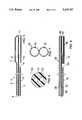
- FIG. 1depicts a cross-sectional view of the distal portion of a balloon dilatation catheter according to the invention
- FIG. 2represents a cross-sectional view along the line 2--2;
- FIGS. 3, 5 and 7represent perspective views of a distal portion of the catheter of the invention as it is being formed
- FIGS. 4, 6, and 8represent cross-sectional views of workpieces from which the catheter of the invention can be formed.
- a balloon dilatation cathetercomprises two substantially longitudinal coextensive lumens wherein the distal portion of one lumen terminates in a dilatation balloon.
- the other, second lumenis open at its distal end and is interrupted near its distal end to provide an opening for a guidewire that extends distally through the open distal end.
- the second lumencomprises a pushing wire that extends from the proximal portion of the catheter to a point proximal, adjacent, or distal to the opening.
- FIG. 1depicts the distal portion of a balloon dilatation catheter 1 having coextensively extending lumens 2 and 3. Lumen 2 terminates in a dilatation balloon 4 which is inflated and deflated through lumen 2.
- Lumen 3contains pushing wire 5, which extends from the proximal end (not shown) of catheter 1 to a position 6 proximal or adjacent to balloon 4.
- the distal portion of pushing wire 5is secured at position 6 by closure, e.g., heat-shrinking, of lumen 3 or by insertion of a plug or other holding means.
- the distal portion 7 of pushing wire 5is preferably tapered distally to provide a smooth transition in axial stiffness.
- the pushing wire 5will become less stiff as the diameter of pushing wire 5 narrows in the distal direction.
- the taperingis substantially linear over the distal portion of the pushing wire 5. Such tapering can extend from about 2 to 40 cm from the distal end of the pushing wire 5.
- the taperingmay be stepped, in discrete reductions, or otherwise nonlinear.
- a guidewire 8is threaded through opening 9 into the enlarged section, i.e., guidewire lumen, 10 of lumen 2. As the guidewire 8 is threaded into section 10, it exits through distal opening 11.
- FIG. 2represents a cross-sectional view showing how lumens 2 and 3 relate to one another and how pushing wire 5 is positioned within lumen 3.
- Lumen walls 12 and 13can each have a thickness of from about 0.3 to 20 mil, preferably from about 0.5 to 10 mil. Lumen wall 13 will most likely be slightly thicker than lumen wall 12.
- the lumen walls 12 and 13are comprised of materials conventional to balloon dilatation catheters. Suitable materials include polyolefins such as polyethylene, polyethylene terepthalate, polyurethanes, polyesters, and various copolymers thereof.
- Pushing wire 5can be made from any rigid, medically acceptable material suitable for such use, including, but not limited to wires or hypotubes comprised of stainless steel or other rigid materials.
- the construction according to the inventionleads to flexibility in product design.
- the choice of pushing wireallows the designer to impart various features to the catheter in the form of various flexibility and pushability combinations.
- a hollow pushing wire, or deletion or removal of the pushing wirewould facilitate infusion of fluids, drugs, and/or contrast media through the catheter into the distal vasculature.
- catheter 1may have at least one additional, coextensive lumen that would similarly facilitate infusion of liquids, drugs and/or contrast media.
- a catheter 1 with a third, coextensive lumen open at its distal endcould have several possible applications.
- a lubricious coating or a section of thin tubing 14 of lubricious materialis sealed into enlarged section 10.
- a lubricious coating or a section of thin tubing 14 of lubricious materialis sealed into enlarged section 10.
- materials suitable for this purposesuch as polytetrafluoroethylene (available as TEFLON® from duPont), polyethylenes, polysiloxanes, etc.
- the tubing section 14can hold the distal portion 7 of pushing wire 5 in position.
- a slitting means (31)is mounted proximally on guidewire 8. Then, as the catheter is withdrawn, the enlarged section 10 engages the slitter, the enlarged section 10 is slit, and catheter 1 is separated from guidewire 8. This would eliminate the requirement for the operator to change hands as catheter 1 is removed.
- the catheter 1may have visual length markings along its shaft that would enable the operator to predict when the catheter 1 would exit the guiding catheter into the vasculature. This would reduce the fluoroscopy time.
- the preferred designwould put the markings directly on the pushing wire 5 (heat shrink tubing rings, inks, paints, etc.). Since the pushing wire 5 is encapsulated within the second lumen 3, the markings would not be exposed to the patient (i.e., markings would not come off, and materials which could be toxic if exposed may be used).
- FIGS. 3 to 8The preparation of a catheter 1 according to the invention is shown in FIGS. 3 to 8. After a double lumen workpiece 20 is prepared, the distal end of the workpiece is sealingly clamped, and heat and inflation pressure are applied to cause the distal portion of lumen 2 to expand to form the wall of balloon 4 and the distal portion of lumen 3 to expand to form enlarged section 10. The location where heat is applied can be varied to vary the respective lengths of balloon 4 and enlarged section 10. Heat sealing or application of suitable adhesive seals the distal portion of balloon 4. Opening 9 is cut into section 10, and opening 11 is maintained or created by trimming the distal portion of the catheter 1.
- Pushing wire 5is then inserted into lumen 3, wherein either the remaining proximal portion 18, or more, of lumen 3 is heat shrunk to cause pushing wire 5 to be positively engaged by lumen 3.
- the distal portion of pushing wire 5could be affixed by suitable means, such as an adhesive or a plug, in lumen 3.
- Workpiece 20can be prepared by methods well-known to those skilled in the art. In a preferred method workpiece 20 can be prepared by blowing extruded tubing 21, a cross-section of which is shown in FIG. 6.
- catheter 1can be prepared from extruded tubing 21 by blowing said tubing 21 under pressure and heating conditions sufficient to produce a catheter piece 25, a cross-section of which is shown in FIG. 7, where the diameters of lumens 26 and 27 correspond substantially to the final diameters of balloon 4 and enlarged section 10, respectively.
- the holes or openings 22 and 23 in tubing 21are not necessarily the same, such that the diameters of lumens 26 and 27 may also differ.
- a pushing wire 29is inserted into lumen 27.
- Pushing wire 29extends the length of lumen 27 to a point slightly distal of opening 28.
- a lubricious liner 30is inserted into the distal end of lumen 27.
- the distal end of lumen 26is sealed, and, while lumen 26 is pressurized, heat is applied to the distal portion of catheter piece 25 to cause lumen 27 to slightly shrink around liner 30, which fixedly engages the distal end of pushing wire 29.
- the portion of catheter piece 25 proximal to the balloonis heated to shrink lumen 26 and to shrink lumen 27 around pushing wire 29.
- the balloon lengthis determined by the location where heat is applied to lumen 26.
- the heatingcan be effected by a point source of heat, where the point source is moved along the exterior of the catheter or the catheter is moved across the point source.
- the heatcan be applied with a broader heat source, such as a hot water bath.
- the source of and/or techniques of heatingwill be apparent to those skilled in the art.
- the workpiecewill optionally be cross-linked prior to working.
- Such cross-linkingcould be effected by chemical or irradiation means.
- the workpiececan be optionally or additionally oriented by mechanical means, such as stretching during blowing.
- the catheters of the inventionare prepared by use of techniques and procedures known to those skilled in the art.
- the pressure and heating conditionswill vary according to the materials used and the results desired, and it is well within the skill of those skilled in the art to determine the proper pressure and heating requirements.
- an additional advantage of the design and preparation according to the inventionis that the catheter can be of integral design and multiple bonding steps can be avoided.
- the balloon and both lumenscan be formed from a single piece. This design permits improvements in manufacturing yields, quality, and reliability due to simplified construction.
- Guidewire 8may be a conventional guidewire, preferably a spring guidewire, as is well known. Typical guidewires are shown in U.S. Pat. Nos. 4,757,827, 4,815,478, 4,813,434, 4,619,274, 4,554,929, 4,545,390, 4,538,622, 3,906,938, 3,973,556, and 4,719,924, all of which are incorporated herein by reference.
- the shaft of guidewire 8could be solid or hollow, such as a hypotube, with an open distal end, to facilitate drug infusion.
- a guiding catheteris inserted into the coronary artery in a conventional manner.
- the guidewire 8is then introduced into the guiding catheter and advanced to and across the lesion.
- the balloon dilatation catheteris inserted onto the guidewire by a back loading technique, where the proximal extremity of the guidewire 8 is inserted backwardly through the tip 11 of the balloon dilatation catheter 1 through the enlarged section 10, and exits opening 9.
- the catheter 1is then advanced along the guidewire 8 to and across the lesion.
- the balloon 4After the balloon 4 has crossed the stenosis or lesion, the balloon 4 can be inflated in a conventional manner by introducing a radiopaque contrast liquid through the lumen 2. After the inflation has occurred and the desired operation has been performed by enlarging the opening in the stenosis, the balloon dilatation catheter 1 can be removed very rapidly by holding the guidewire 8 stationary and withdrawing the balloon dilatation catheter.
- the balloon dilatation cathetercan be removed and thereafter the guiding catheter can be removed.
Landscapes
- Health & Medical Sciences (AREA)
- Life Sciences & Earth Sciences (AREA)
- Heart & Thoracic Surgery (AREA)
- Biomedical Technology (AREA)
- Biophysics (AREA)
- Pulmonology (AREA)
- Engineering & Computer Science (AREA)
- Anesthesiology (AREA)
- Child & Adolescent Psychology (AREA)
- Hematology (AREA)
- Animal Behavior & Ethology (AREA)
- General Health & Medical Sciences (AREA)
- Public Health (AREA)
- Veterinary Medicine (AREA)
- Vascular Medicine (AREA)
- Media Introduction/Drainage Providing Device (AREA)
Abstract
Description
Claims (10)
Priority Applications (10)
| Application Number | Priority Date | Filing Date | Title |
|---|---|---|---|
| US07/969,946US5315747A (en) | 1992-10-30 | 1992-10-30 | Method of preparing a balloon dilatation catheter |
| EP93117442AEP0595308B1 (en) | 1992-10-30 | 1993-10-27 | Rapid exchange catheter |
| DE4336684ADE4336684A1 (en) | 1992-10-30 | 1993-10-27 | Quick change catheter |
| DE69331307TDE69331307T2 (en) | 1992-10-30 | 1993-10-27 | Catheter, which can be replaced quickly |
| AU50318/93AAU5031893A (en) | 1992-10-30 | 1993-10-27 | Rapid exchange catheter |
| ZA938021AZA938021B (en) | 1992-10-30 | 1993-10-27 | Rapid exchange catheter |
| CA002109476ACA2109476C (en) | 1992-10-30 | 1993-10-28 | Rapid exchange catheter |
| JP5292368AJPH07533A (en) | 1992-10-30 | 1993-10-29 | Promptly exchangeable catheter |
| US08/853,209USRE36104E (en) | 1992-10-30 | 1997-05-09 | Dilation catheter with eccentric balloon |
| AU26176/97AAU694389B2 (en) | 1992-10-30 | 1997-06-20 | Rapid exchange catheter |
Applications Claiming Priority (1)
| Application Number | Priority Date | Filing Date | Title |
|---|---|---|---|
| US07/969,946US5315747A (en) | 1992-10-30 | 1992-10-30 | Method of preparing a balloon dilatation catheter |
Related Child Applications (1)
| Application Number | Title | Priority Date | Filing Date |
|---|---|---|---|
| US08/853,209ContinuationUSRE36104E (en) | 1992-10-30 | 1997-05-09 | Dilation catheter with eccentric balloon |
Publications (1)
| Publication Number | Publication Date |
|---|---|
| US5315747Atrue US5315747A (en) | 1994-05-31 |
Family
ID=25516213
Family Applications (2)
| Application Number | Title | Priority Date | Filing Date |
|---|---|---|---|
| US07/969,946Expired - LifetimeUS5315747A (en) | 1992-10-30 | 1992-10-30 | Method of preparing a balloon dilatation catheter |
| US08/853,209Expired - LifetimeUSRE36104E (en) | 1992-10-30 | 1997-05-09 | Dilation catheter with eccentric balloon |
Family Applications After (1)
| Application Number | Title | Priority Date | Filing Date |
|---|---|---|---|
| US08/853,209Expired - LifetimeUSRE36104E (en) | 1992-10-30 | 1997-05-09 | Dilation catheter with eccentric balloon |
Country Status (1)
| Country | Link |
|---|---|
| US (2) | US5315747A (en) |
Cited By (16)
| Publication number | Priority date | Publication date | Assignee | Title |
|---|---|---|---|---|
| WO1996004034A1 (en)* | 1994-08-05 | 1996-02-15 | Medtronic, Inc. | Catheter balloon distal bond |
| US5554120A (en)* | 1994-07-25 | 1996-09-10 | Advanced Cardiovascular Systems, Inc. | Polymer blends for use in making medical devices including catheters and balloons for dilatation catheters |
| US5690642A (en) | 1996-01-18 | 1997-11-25 | Cook Incorporated | Rapid exchange stent delivery balloon catheter |
| US5713854A (en)* | 1995-11-01 | 1998-02-03 | Cordis Corporation | Method and apparatus for dilatation catheterization |
| US5849846A (en)* | 1994-07-25 | 1998-12-15 | Advanced Cardiovascular Systems, Inc. | Balloons for medical catheters |
| EP0785807A4 (en)* | 1995-06-16 | 2000-01-12 | Cordis Corp | Stent delivery system |
| US6183438B1 (en)* | 2000-01-04 | 2001-02-06 | Ramon Berguer | Catheter with centering wire |
| US6599462B1 (en)* | 1997-06-11 | 2003-07-29 | Advanced Cardiovascular Systems, Inc. | Balloon catheter having non-bonded integral balloon and methods for its manufacture |
| US20030149467A1 (en)* | 2001-11-09 | 2003-08-07 | Linder Richard J. | Methods, systems and devices for delivering stents |
| US20040064179A1 (en)* | 2001-11-09 | 2004-04-01 | Rubicon Medical, Inc. | Stent delivery device with embolic protection |
| US20050137526A1 (en)* | 2003-12-17 | 2005-06-23 | Fidelis Machado | Balloon catheter with positioning pocket |
| US20060206137A1 (en)* | 2003-04-24 | 2006-09-14 | Invatec S.R.1. | Balloon structure and balloon catheter |
| US20090105808A1 (en)* | 2001-03-14 | 2009-04-23 | Boston Scientific Scimed, Inc. | Rapid Exchange Stent Delivery System and Associated Components |
| WO2023283253A1 (en)* | 2021-07-07 | 2023-01-12 | Mekal, LLC | Multi-lumen intravascular catheter with inner converging lumens for multiple guidewire control |
| CN118403271A (en)* | 2024-05-01 | 2024-07-30 | 无锡市第二人民医院 | Method for manufacturing a urinary catheter with a three-chamber balloon at the top |
| US12274467B2 (en) | 2019-12-20 | 2025-04-15 | Kaneka Corporation | Balloon catheter |
Families Citing this family (45)
| Publication number | Priority date | Publication date | Assignee | Title |
|---|---|---|---|---|
| US6325818B1 (en)* | 1999-10-07 | 2001-12-04 | Innercool Therapies, Inc. | Inflatable cooling apparatus for selective organ hypothermia |
| US6231595B1 (en) | 1998-03-31 | 2001-05-15 | Innercool Therapies, Inc. | Circulating fluid hypothermia method and apparatus |
| US7238168B2 (en)* | 2000-06-02 | 2007-07-03 | Avantec Vascular Corporation | Exchangeable catheter |
| US6537294B1 (en)* | 2000-10-17 | 2003-03-25 | Advanced Cardiovascular Systems, Inc. | Delivery systems for embolic filter devices |
| US20050021123A1 (en)* | 2001-04-30 | 2005-01-27 | Jurgen Dorn | Variable speed self-expanding stent delivery system and luer locking connector |
| US20030191436A1 (en)* | 2002-04-05 | 2003-10-09 | Horvers Ronald Adrianus Maria | Balloon catheter |
| AU2002350164A1 (en) | 2001-11-08 | 2003-05-19 | William D. Hare | Rapid exchange catheter with stent deployment, therapeutic infusion, and lesion sampling features |
| WO2008088766A1 (en) | 2002-03-22 | 2008-07-24 | Cordis Corporation | Rapid-exchange balloon catheter shaft and method |
| US6953431B2 (en)* | 2002-04-11 | 2005-10-11 | University Of South Florida | Eccentric dilation balloons for use with endoscopes |
| US7300415B2 (en)* | 2002-12-20 | 2007-11-27 | Advanced Cardiovascular Systems, Inc. | Balloon catheter having an external guidewire |
| US7316709B2 (en)* | 2004-01-13 | 2008-01-08 | Advanced Cardiovascular Systems, Inc. | Balloon catheter having a textured member for enhancing balloon or stent retention |
| EP1974684A3 (en)* | 2004-09-17 | 2009-03-18 | The Spectranetics Corporation | Apparatus and methods for directional delivery of laser energy |
| US8545488B2 (en)* | 2004-09-17 | 2013-10-01 | The Spectranetics Corporation | Cardiovascular imaging system |
| US8628519B2 (en) | 2004-09-17 | 2014-01-14 | The Spectranetics Corporation | Rapid exchange bias laser catheter design |
| ATE459312T1 (en) | 2005-08-17 | 2010-03-15 | Bard Inc C R | VARIABLE SPEED STENT DELIVERY SYSTEM |
| US8808346B2 (en)* | 2006-01-13 | 2014-08-19 | C. R. Bard, Inc. | Stent delivery system |
| US11026822B2 (en) | 2006-01-13 | 2021-06-08 | C. R. Bard, Inc. | Stent delivery system |
| US9023075B2 (en)* | 2006-06-30 | 2015-05-05 | Cvdevices, Llc | Devices, systems, and methods for lead delivery |
| GB0615658D0 (en) | 2006-08-07 | 2006-09-13 | Angiomed Ag | Hand-held actuator device |
| GB0713497D0 (en)* | 2007-07-11 | 2007-08-22 | Angiomed Ag | Device for catheter sheath retraction |
| US9848952B2 (en) | 2007-10-24 | 2017-12-26 | The Spectranetics Corporation | Liquid light guide catheter having biocompatible liquid light guide medium |
| US9066742B2 (en) | 2007-11-09 | 2015-06-30 | The Spectranetics Corporation | Intra-vascular device with pressure detection capabilities using pressure sensitive material |
| US9421065B2 (en) | 2008-04-02 | 2016-08-23 | The Spectranetics Corporation | Liquid light-guide catheter with optically diverging tip |
| US8979828B2 (en)* | 2008-07-21 | 2015-03-17 | The Spectranetics Corporation | Tapered liquid light guide |
| US20100094075A1 (en)* | 2008-10-10 | 2010-04-15 | Hologic Inc. | Expandable medical devices with reinforced elastomeric members and methods employing the same |
| US20100114081A1 (en) | 2008-11-05 | 2010-05-06 | Spectranetics | Biasing laser catheter: monorail design |
| US9408665B2 (en) | 2008-12-12 | 2016-08-09 | The Spectranetics Corporation | Offset catheter |
| US8702773B2 (en) | 2008-12-17 | 2014-04-22 | The Spectranetics Corporation | Eccentric balloon laser catheter |
| US20100305678A1 (en)* | 2009-05-27 | 2010-12-02 | Khaldoon Alaswad | Thrombectomy and Balloon Angioplasty/Stenting Device |
| GB201017834D0 (en) | 2010-10-21 | 2010-12-01 | Angiomed Ag | System to deliver a bodily implant |
| EP2696929A1 (en) | 2011-04-11 | 2014-02-19 | The Spectranetics Corporation | Needle and guidewire holder |
| US9233015B2 (en) | 2012-06-15 | 2016-01-12 | Trivascular, Inc. | Endovascular delivery system with an improved radiopaque marker scheme |
| US9398921B2 (en) | 2013-01-30 | 2016-07-26 | Invatec S.P.A. | Catheter with deflectable tip |
| US9095374B2 (en) | 2013-01-30 | 2015-08-04 | Invatec S.P.A. | Catheter with deflectable tip |
| US9623211B2 (en) | 2013-03-13 | 2017-04-18 | The Spectranetics Corporation | Catheter movement control |
| US11642169B2 (en) | 2013-03-14 | 2023-05-09 | The Spectranetics Corporation | Smart multiplexed medical laser system |
| US9757200B2 (en) | 2013-03-14 | 2017-09-12 | The Spectranetics Corporation | Intelligent catheter |
| US10758308B2 (en) | 2013-03-14 | 2020-09-01 | The Spectranetics Corporation | Controller to select optical channel parameters in a catheter |
| US10987168B2 (en) | 2014-05-29 | 2021-04-27 | Spectranetics Llc | System and method for coordinated laser delivery and imaging |
| WO2016069754A1 (en) | 2014-10-29 | 2016-05-06 | The Spectranetics Corporation | Laser energy delivery devices including laser transmission detection systems and methods |
| US10492863B2 (en) | 2014-10-29 | 2019-12-03 | The Spectranetics Corporation | Laser energy delivery devices including laser transmission detection systems and methods |
| US10646118B2 (en) | 2014-12-30 | 2020-05-12 | Regents Of The University Of Minnesota | Laser catheter with use of reflected light to determine material type in vascular system |
| US10646275B2 (en) | 2014-12-30 | 2020-05-12 | Regents Of The University Of Minnesota | Laser catheter with use of determined material type in vascular system in ablation of material |
| US10646274B2 (en) | 2014-12-30 | 2020-05-12 | Regents Of The University Of Minnesota | Laser catheter with use of reflected light and force indication to determine material type in vascular system |
| USD775728S1 (en) | 2015-07-02 | 2017-01-03 | The Spectranetics Corporation | Medical device handle |
Citations (42)
| Publication number | Priority date | Publication date | Assignee | Title |
|---|---|---|---|---|
| US3906938A (en)* | 1974-09-03 | 1975-09-23 | Lake Region Manufacturing Comp | Coil spring wire guide |
| US3973556A (en)* | 1975-06-20 | 1976-08-10 | Lake Region Manufacturing Company, Inc. | Smoothened coil spring wire guide |
| US4349033A (en)* | 1980-11-06 | 1982-09-14 | Eden Robert D | Intrauterine catheter |
| US4411055A (en)* | 1980-05-19 | 1983-10-25 | Advanced Cardiovascular Systems, Inc. | Vascular guiding catheter assembly and vascular dilating catheter assembly and a combination thereof and methods for making the same |
| US4467790A (en)* | 1981-04-13 | 1984-08-28 | Peter Schiff | Percutaneous balloon |
| US4538622A (en)* | 1983-11-10 | 1985-09-03 | Advanced Cardiovascular Systems, Inc. | Guide wire for catheters |
| US4545390A (en)* | 1982-09-22 | 1985-10-08 | C. R. Bard, Inc. | Steerable guide wire for balloon dilatation procedure |
| US4554929A (en)* | 1983-07-13 | 1985-11-26 | Advanced Cardiovascular Systems, Inc. | Catheter guide wire with short spring tip and method of using the same |
| US4601713A (en)* | 1985-06-11 | 1986-07-22 | Genus Catheter Technologies, Inc. | Variable diameter catheter |
| US4619274A (en)* | 1985-04-18 | 1986-10-28 | Advanced Cardiovascular Systems, Inc. | Torsional guide wire with attenuated diameter |
| US4710181A (en)* | 1985-06-11 | 1987-12-01 | Genus Catheter Technologies, Inc. | Variable diameter catheter |
| US4719924A (en)* | 1986-09-09 | 1988-01-19 | C. R. Bard, Inc. | Small diameter steerable guidewire with adjustable tip |
| US4734093A (en)* | 1985-11-21 | 1988-03-29 | Sarcem S.A. | Remote controlled catheter having a micro-balloon |
| US4738666A (en)* | 1985-06-11 | 1988-04-19 | Genus Catheter Technologies, Inc. | Variable diameter catheter |
| US4757827A (en)* | 1987-02-17 | 1988-07-19 | Versaflex Delivery Systems Inc. | Steerable guidewire with deflectable tip |
| US4762129A (en)* | 1984-11-23 | 1988-08-09 | Tassilo Bonzel | Dilatation catheter |
| US4784639A (en)* | 1987-07-06 | 1988-11-15 | Patel Piyush V | Catheter and method of inserting catheter |
| US4787899A (en)* | 1983-12-09 | 1988-11-29 | Lazarus Harrison M | Intraluminal graft device, system and method |
| US4793350A (en)* | 1987-01-06 | 1988-12-27 | Advanced Cardiovascular Systems, Inc. | Liquid filled low profile dilatation catheter |
| US4798598A (en)* | 1986-05-23 | 1989-01-17 | Sarcem S.A. | Guide for a catheter |
| US4813434A (en)* | 1987-02-17 | 1989-03-21 | Medtronic Versaflex, Inc. | Steerable guidewire with deflectable tip |
| US4815478A (en)* | 1987-02-17 | 1989-03-28 | Medtronic Versaflex, Inc. | Steerable guidewire with deflectable tip |
| US4820349A (en)* | 1987-08-21 | 1989-04-11 | C. R. Bard, Inc. | Dilatation catheter with collapsible outer diameter |
| US4927413A (en)* | 1987-08-24 | 1990-05-22 | Progressive Angioplasty Systems, Inc. | Catheter for balloon angioplasty |
| US4932413A (en)* | 1989-03-13 | 1990-06-12 | Schneider (Usa), Inc. | Guidewire exchange catheter |
| US4944740A (en)* | 1984-09-18 | 1990-07-31 | Medtronic Versaflex, Inc. | Outer exchange catheter system |
| US4958634A (en)* | 1987-05-06 | 1990-09-25 | Jang G David | Limacon geometry balloon angioplasty catheter systems and method of making same |
| US4964409A (en)* | 1989-05-11 | 1990-10-23 | Advanced Cardiovascular Systems, Inc. | Flexible hollow guiding member with means for fluid communication therethrough |
| US4969890A (en)* | 1987-07-10 | 1990-11-13 | Nippon Zeon Co., Ltd. | Catheter |
| US4976690A (en)* | 1989-08-10 | 1990-12-11 | Scimed Life Systems, Inc. | Variable stiffness angioplasty catheter |
| US5041089A (en)* | 1987-12-11 | 1991-08-20 | Devices For Vascular Intervention, Inc. | Vascular dilation catheter construction |
| US5040548A (en)* | 1989-06-01 | 1991-08-20 | Yock Paul G | Angioplasty mehtod |
| US5049131A (en)* | 1989-05-31 | 1991-09-17 | Ashridge Ag | Balloon catheter |
| US5057083A (en)* | 1989-07-25 | 1991-10-15 | C. R. Bard, Inc. | Vascular dilator with truncated tip |
| US5059186A (en)* | 1988-03-07 | 1991-10-22 | Vitaphore Corporation | Percutaneous access device |
| US5059183A (en)* | 1989-09-01 | 1991-10-22 | Neal Semrad | Stop guide wire and double ended obturator-catheter-sheath system and method of use of same |
| US5098393A (en)* | 1988-05-31 | 1992-03-24 | Kurt Amplatz | Medical introducer and valve assembly |
| US5104399A (en)* | 1986-12-10 | 1992-04-14 | Endovascular Technologies, Inc. | Artificial graft and implantation method |
| US5106368A (en)* | 1990-04-20 | 1992-04-21 | Cook Incorporated | Collapsible lumen catheter for extracorporeal treatment |
| US5116309A (en)* | 1989-01-25 | 1992-05-26 | Coll Milton E | Ureteral stent-catheter system having varying diameter stent |
| US5135535A (en)* | 1991-06-11 | 1992-08-04 | Advanced Cardiovascular Systems, Inc. | Catheter system with catheter and guidewire exchange |
| US5143093A (en)* | 1990-10-05 | 1992-09-01 | Harvinder Sahota | Methods of angioplasty treatment of stenotic regions |
Family Cites Families (12)
| Publication number | Priority date | Publication date | Assignee | Title |
|---|---|---|---|---|
| US3811448A (en)* | 1972-10-25 | 1974-05-21 | A Morton | Urinary drainage catheter |
| CH616337A5 (en)* | 1977-10-21 | 1980-03-31 | Schneider Medintag Ag | |
| US4323071A (en)* | 1978-04-24 | 1982-04-06 | Advanced Catheter Systems, Inc. | Vascular guiding catheter assembly and vascular dilating catheter assembly and a combination thereof and methods of making the same |
| US4493711A (en)* | 1982-06-25 | 1985-01-15 | Thomas J. Fogarty | Tubular extrusion catheter |
| US4573470A (en)* | 1984-05-30 | 1986-03-04 | Advanced Cardiovascular Systems, Inc. | Low-profile steerable intraoperative balloon dilitation catheter |
| GB8417562D0 (en)* | 1984-07-10 | 1984-08-15 | Surgical Design Services | Fasteners |
| US4643186A (en)* | 1985-10-30 | 1987-02-17 | Rca Corporation | Percutaneous transluminal microwave catheter angioplasty |
| US4641649A (en)* | 1985-10-30 | 1987-02-10 | Rca Corporation | Method and apparatus for high frequency catheter ablation |
| US5061273A (en)* | 1989-06-01 | 1991-10-29 | Yock Paul G | Angioplasty apparatus facilitating rapid exchanges |
| US4790315A (en)* | 1986-09-02 | 1988-12-13 | Advanced Cardiovascular Systems, Inc. | Perfusion dilatation catheter and method of manufacture |
| US5090958A (en)* | 1988-11-23 | 1992-02-25 | Harvinder Sahota | Balloon catheters |
| US5045061A (en)* | 1990-02-02 | 1991-09-03 | C. R. Bard, Inc. | Balloon catheter and locking guidewire system |
- 1992
- 1992-10-30USUS07/969,946patent/US5315747A/ennot_activeExpired - Lifetime
- 1997
- 1997-05-09USUS08/853,209patent/USRE36104E/ennot_activeExpired - Lifetime
Patent Citations (44)
| Publication number | Priority date | Publication date | Assignee | Title |
|---|---|---|---|---|
| US3906938A (en)* | 1974-09-03 | 1975-09-23 | Lake Region Manufacturing Comp | Coil spring wire guide |
| US3973556A (en)* | 1975-06-20 | 1976-08-10 | Lake Region Manufacturing Company, Inc. | Smoothened coil spring wire guide |
| US4411055A (en)* | 1980-05-19 | 1983-10-25 | Advanced Cardiovascular Systems, Inc. | Vascular guiding catheter assembly and vascular dilating catheter assembly and a combination thereof and methods for making the same |
| US4349033A (en)* | 1980-11-06 | 1982-09-14 | Eden Robert D | Intrauterine catheter |
| US4467790A (en)* | 1981-04-13 | 1984-08-28 | Peter Schiff | Percutaneous balloon |
| US4545390A (en)* | 1982-09-22 | 1985-10-08 | C. R. Bard, Inc. | Steerable guide wire for balloon dilatation procedure |
| US4554929A (en)* | 1983-07-13 | 1985-11-26 | Advanced Cardiovascular Systems, Inc. | Catheter guide wire with short spring tip and method of using the same |
| US4538622A (en)* | 1983-11-10 | 1985-09-03 | Advanced Cardiovascular Systems, Inc. | Guide wire for catheters |
| US4787899A (en)* | 1983-12-09 | 1988-11-29 | Lazarus Harrison M | Intraluminal graft device, system and method |
| US4944740A (en)* | 1984-09-18 | 1990-07-31 | Medtronic Versaflex, Inc. | Outer exchange catheter system |
| US4762129B1 (en)* | 1984-11-23 | 1991-07-02 | Tassilo Bonzel | |
| US4762129A (en)* | 1984-11-23 | 1988-08-09 | Tassilo Bonzel | Dilatation catheter |
| US4619274A (en)* | 1985-04-18 | 1986-10-28 | Advanced Cardiovascular Systems, Inc. | Torsional guide wire with attenuated diameter |
| US4710181A (en)* | 1985-06-11 | 1987-12-01 | Genus Catheter Technologies, Inc. | Variable diameter catheter |
| US4738666A (en)* | 1985-06-11 | 1988-04-19 | Genus Catheter Technologies, Inc. | Variable diameter catheter |
| US4601713A (en)* | 1985-06-11 | 1986-07-22 | Genus Catheter Technologies, Inc. | Variable diameter catheter |
| US4734093A (en)* | 1985-11-21 | 1988-03-29 | Sarcem S.A. | Remote controlled catheter having a micro-balloon |
| US4798598A (en)* | 1986-05-23 | 1989-01-17 | Sarcem S.A. | Guide for a catheter |
| US4719924A (en)* | 1986-09-09 | 1988-01-19 | C. R. Bard, Inc. | Small diameter steerable guidewire with adjustable tip |
| US5104399A (en)* | 1986-12-10 | 1992-04-14 | Endovascular Technologies, Inc. | Artificial graft and implantation method |
| US4793350A (en)* | 1987-01-06 | 1988-12-27 | Advanced Cardiovascular Systems, Inc. | Liquid filled low profile dilatation catheter |
| US4813434A (en)* | 1987-02-17 | 1989-03-21 | Medtronic Versaflex, Inc. | Steerable guidewire with deflectable tip |
| US4815478A (en)* | 1987-02-17 | 1989-03-28 | Medtronic Versaflex, Inc. | Steerable guidewire with deflectable tip |
| US4757827A (en)* | 1987-02-17 | 1988-07-19 | Versaflex Delivery Systems Inc. | Steerable guidewire with deflectable tip |
| US4958634A (en)* | 1987-05-06 | 1990-09-25 | Jang G David | Limacon geometry balloon angioplasty catheter systems and method of making same |
| US4784639A (en)* | 1987-07-06 | 1988-11-15 | Patel Piyush V | Catheter and method of inserting catheter |
| US4969890A (en)* | 1987-07-10 | 1990-11-13 | Nippon Zeon Co., Ltd. | Catheter |
| US4820349A (en)* | 1987-08-21 | 1989-04-11 | C. R. Bard, Inc. | Dilatation catheter with collapsible outer diameter |
| US4927413A (en)* | 1987-08-24 | 1990-05-22 | Progressive Angioplasty Systems, Inc. | Catheter for balloon angioplasty |
| US5041089A (en)* | 1987-12-11 | 1991-08-20 | Devices For Vascular Intervention, Inc. | Vascular dilation catheter construction |
| US5059186A (en)* | 1988-03-07 | 1991-10-22 | Vitaphore Corporation | Percutaneous access device |
| US5098393A (en)* | 1988-05-31 | 1992-03-24 | Kurt Amplatz | Medical introducer and valve assembly |
| US5116309A (en)* | 1989-01-25 | 1992-05-26 | Coll Milton E | Ureteral stent-catheter system having varying diameter stent |
| US4932413A (en)* | 1989-03-13 | 1990-06-12 | Schneider (Usa), Inc. | Guidewire exchange catheter |
| US4947864A (en)* | 1989-03-13 | 1990-08-14 | Schneider (U.S.A.), Inc. A Pfizer Company | Guidewire exchange catheter |
| US4964409A (en)* | 1989-05-11 | 1990-10-23 | Advanced Cardiovascular Systems, Inc. | Flexible hollow guiding member with means for fluid communication therethrough |
| US5049131A (en)* | 1989-05-31 | 1991-09-17 | Ashridge Ag | Balloon catheter |
| US5040548A (en)* | 1989-06-01 | 1991-08-20 | Yock Paul G | Angioplasty mehtod |
| US5057083A (en)* | 1989-07-25 | 1991-10-15 | C. R. Bard, Inc. | Vascular dilator with truncated tip |
| US4976690A (en)* | 1989-08-10 | 1990-12-11 | Scimed Life Systems, Inc. | Variable stiffness angioplasty catheter |
| US5059183A (en)* | 1989-09-01 | 1991-10-22 | Neal Semrad | Stop guide wire and double ended obturator-catheter-sheath system and method of use of same |
| US5106368A (en)* | 1990-04-20 | 1992-04-21 | Cook Incorporated | Collapsible lumen catheter for extracorporeal treatment |
| US5143093A (en)* | 1990-10-05 | 1992-09-01 | Harvinder Sahota | Methods of angioplasty treatment of stenotic regions |
| US5135535A (en)* | 1991-06-11 | 1992-08-04 | Advanced Cardiovascular Systems, Inc. | Catheter system with catheter and guidewire exchange |
Cited By (26)
| Publication number | Priority date | Publication date | Assignee | Title |
|---|---|---|---|---|
| US5849846A (en)* | 1994-07-25 | 1998-12-15 | Advanced Cardiovascular Systems, Inc. | Balloons for medical catheters |
| US5554120A (en)* | 1994-07-25 | 1996-09-10 | Advanced Cardiovascular Systems, Inc. | Polymer blends for use in making medical devices including catheters and balloons for dilatation catheters |
| US5565523A (en)* | 1994-07-25 | 1996-10-15 | Advanced Cardiovascular Systems, Inc. | Polymer blends for use in making medical devices including catheters and balloons for dilatation catheters |
| US6013728A (en)* | 1994-07-25 | 2000-01-11 | Advanced Cardiovascular Systems, Inc. | Polymer blends for use in making medical devices including catheters and balloons for dilatation catheters |
| US5747591A (en)* | 1994-07-25 | 1998-05-05 | Advanced Cardiovascular Systems, Inc. | Polymer blends for use in making medical devices including catheters and balloons for dilation catheters |
| WO1996004034A1 (en)* | 1994-08-05 | 1996-02-15 | Medtronic, Inc. | Catheter balloon distal bond |
| EP0785807A4 (en)* | 1995-06-16 | 2000-01-12 | Cordis Corp | Stent delivery system |
| US5895405A (en)* | 1995-11-01 | 1999-04-20 | Cordis Corporation | Method and apparatus for dilatation catheterization |
| US5713854A (en)* | 1995-11-01 | 1998-02-03 | Cordis Corporation | Method and apparatus for dilatation catheterization |
| US5690642A (en) | 1996-01-18 | 1997-11-25 | Cook Incorporated | Rapid exchange stent delivery balloon catheter |
| US6599462B1 (en)* | 1997-06-11 | 2003-07-29 | Advanced Cardiovascular Systems, Inc. | Balloon catheter having non-bonded integral balloon and methods for its manufacture |
| US6183438B1 (en)* | 2000-01-04 | 2001-02-06 | Ramon Berguer | Catheter with centering wire |
| US20090105808A1 (en)* | 2001-03-14 | 2009-04-23 | Boston Scientific Scimed, Inc. | Rapid Exchange Stent Delivery System and Associated Components |
| US8685078B2 (en) | 2001-03-14 | 2014-04-01 | Boston Scientific Scimed, Inc. | Rapid exchange stent delivery system and associated components |
| US8444685B2 (en)* | 2001-03-14 | 2013-05-21 | Boston Scientific Scimed, Inc. | Rapid exchange stent delivery system and associated components |
| US20030149467A1 (en)* | 2001-11-09 | 2003-08-07 | Linder Richard J. | Methods, systems and devices for delivering stents |
| US7594926B2 (en) | 2001-11-09 | 2009-09-29 | Boston Scientific Scimed, Inc. | Methods, systems and devices for delivering stents |
| US7708770B2 (en) | 2001-11-09 | 2010-05-04 | Boston Scientific Scimed, Inc. | Stent delivery device with embolic protection |
| US8579957B2 (en) | 2001-11-09 | 2013-11-12 | Boston Scientific Scimed, Inc. | Stent delivery device with embolic protection |
| US20040064179A1 (en)* | 2001-11-09 | 2004-04-01 | Rubicon Medical, Inc. | Stent delivery device with embolic protection |
| US20060206137A1 (en)* | 2003-04-24 | 2006-09-14 | Invatec S.R.1. | Balloon structure and balloon catheter |
| US7727188B2 (en)* | 2003-12-17 | 2010-06-01 | Convatec Technologies Inc. | Balloon catheter with positioning pocket |
| US20050137526A1 (en)* | 2003-12-17 | 2005-06-23 | Fidelis Machado | Balloon catheter with positioning pocket |
| US12274467B2 (en) | 2019-12-20 | 2025-04-15 | Kaneka Corporation | Balloon catheter |
| WO2023283253A1 (en)* | 2021-07-07 | 2023-01-12 | Mekal, LLC | Multi-lumen intravascular catheter with inner converging lumens for multiple guidewire control |
| CN118403271A (en)* | 2024-05-01 | 2024-07-30 | 无锡市第二人民医院 | Method for manufacturing a urinary catheter with a three-chamber balloon at the top |
Also Published As
| Publication number | Publication date |
|---|---|
| USRE36104E (en) | 1999-02-16 |
Similar Documents
| Publication | Publication Date | Title |
|---|---|---|
| US5315747A (en) | Method of preparing a balloon dilatation catheter | |
| US5531690A (en) | Rapid exchange catheter | |
| US5520647A (en) | Rapid withdrawal catheter | |
| US5413557A (en) | Dilatation catheter with eccentric balloon | |
| US5669880A (en) | Stent delivery system | |
| US8308749B2 (en) | Catheter with disruptable guidewire channel | |
| US5334154A (en) | Perfusion type dilatation catheter having perfusion ports with depressed proximal edges | |
| US4932959A (en) | Vascular catheter with releasably secured guidewire | |
| EP0650740B1 (en) | Interventional catheter | |
| US5279562A (en) | Low profile perfusion-type dilatation catheter | |
| US6695863B1 (en) | Sheath for an adjustable length balloon | |
| USRE36857E (en) | Interlocking peel-away dilation catheter | |
| US6923788B2 (en) | Catheter having a low-friction guidewire lumen and method of manufacture | |
| US5496346A (en) | Reinforced balloon dilatation catheter with slitted exchange sleeve and method | |
| US6471673B1 (en) | Catheter with multilayer tube | |
| US5980486A (en) | Rapidly exchangeable coronary catheter | |
| WO1995028983A1 (en) | Active perfusion dilatation catheter | |
| EP0595308B1 (en) | Rapid exchange catheter | |
| EP0537278B1 (en) | Ptca catheter having an optionally fixated corewire | |
| CA2197461C (en) | Stent delivery system |
Legal Events
| Date | Code | Title | Description |
|---|---|---|---|
| AS | Assignment | Owner name:PAMEDA N.V., NAMIBIA Free format text:ASSIGNMENT OF ASSIGNORS INTEREST.;ASSIGNOR:SOLAR, RONALD J.;REEL/FRAME:006482/0096 Effective date:19921119 | |
| AS | Assignment | Owner name:PAMEDA N.V., NETHERLANDS ANTILLES Free format text:ASSIGNMENT OF ASSIGNORS INTEREST;ASSIGNOR:SOLAR, RONALD J.;REEL/FRAME:006674/0417 Effective date:19930823 | |
| STCF | Information on status: patent grant | Free format text:PATENTED CASE | |
| FEPP | Fee payment procedure | Free format text:PAYOR NUMBER ASSIGNED (ORIGINAL EVENT CODE: ASPN); ENTITY STATUS OF PATENT OWNER: SMALL ENTITY | |
| AS | Assignment | Owner name:CORDIS CORPORATION, FLORIDA Free format text:ASSIGNMENT OF ASSIGNORS INTEREST;ASSIGNOR:PAMEDA, N.V.;REEL/FRAME:007854/0349 Effective date:19960220 | |
| FEPP | Fee payment procedure | Free format text:PAYER NUMBER DE-ASSIGNED (ORIGINAL EVENT CODE: RMPN); ENTITY STATUS OF PATENT OWNER: SMALL ENTITY Free format text:PAYOR NUMBER ASSIGNED (ORIGINAL EVENT CODE: ASPN); ENTITY STATUS OF PATENT OWNER: SMALL ENTITY | |
| FPAY | Fee payment | Year of fee payment:4 | |
| FEPP | Fee payment procedure | Free format text:PAYER NUMBER DE-ASSIGNED (ORIGINAL EVENT CODE: RMPN); ENTITY STATUS OF PATENT OWNER: SMALL ENTITY Free format text:PAYOR NUMBER ASSIGNED (ORIGINAL EVENT CODE: ASPN); ENTITY STATUS OF PATENT OWNER: SMALL ENTITY | |
| FPAY | Fee payment | Year of fee payment:8 | |
| FPAY | Fee payment | Year of fee payment:12 |