US5315258A - Method and apparatus for determining the moisture content of a material - Google Patents
Method and apparatus for determining the moisture content of a materialDownload PDFInfo
- Publication number
- US5315258A US5315258AUS07/859,893US85989392AUS5315258AUS 5315258 AUS5315258 AUS 5315258AUS 85989392 AUS85989392 AUS 85989392AUS 5315258 AUS5315258 AUS 5315258A
- Authority
- US
- United States
- Prior art keywords
- signal
- frequency
- microwave
- moisture content
- measured
- Prior art date
- Legal status (The legal status is an assumption and is not a legal conclusion. Google has not performed a legal analysis and makes no representation as to the accuracy of the status listed.)
- Expired - Lifetime
Links
- 239000000463materialSubstances0.000titleclaimsabstractdescription134
- 238000000034methodMethods0.000titleabstractdescription50
- 230000008859changeEffects0.000claimsabstractdescription23
- 238000005259measurementMethods0.000claimsdescription81
- 238000007620mathematical functionMethods0.000claimsdescription3
- 239000002023woodSubstances0.000description14
- 238000001208nuclear magnetic resonance pulse sequenceMethods0.000description12
- 238000005314correlation functionMethods0.000description7
- 235000008331Pinus X rigitaedaNutrition0.000description6
- 235000011613Pinus brutiaNutrition0.000description6
- 241000018646Pinus brutiaSpecies0.000description6
- 230000003111delayed effectEffects0.000description4
- XLYOFNOQVPJJNP-UHFFFAOYSA-NwaterSubstancesOXLYOFNOQVPJJNP-UHFFFAOYSA-N0.000description4
- 101000623895Bos taurus Mucin-15Proteins0.000description3
- 230000008901benefitEffects0.000description3
- 238000001514detection methodMethods0.000description3
- 230000010363phase shiftEffects0.000description3
- 229920001131Pulp (paper)Polymers0.000description2
- 230000033228biological regulationEffects0.000description2
- 238000004364calculation methodMethods0.000description2
- 230000008569processEffects0.000description2
- 230000005855radiationEffects0.000description2
- 230000000630rising effectEffects0.000description2
- 238000005070samplingMethods0.000description2
- 230000001960triggered effectEffects0.000description2
- 230000009471actionEffects0.000description1
- 238000004458analytical methodMethods0.000description1
- 239000007900aqueous suspensionSubstances0.000description1
- 238000005311autocorrelation functionMethods0.000description1
- 230000005540biological transmissionEffects0.000description1
- 239000003990capacitorSubstances0.000description1
- 238000004590computer programMethods0.000description1
- 238000010924continuous productionMethods0.000description1
- 125000004122cyclic groupChemical group0.000description1
- 230000007423decreaseEffects0.000description1
- 230000003247decreasing effectEffects0.000description1
- 230000009977dual effectEffects0.000description1
- 230000000694effectsEffects0.000description1
- 239000000835fiberSubstances0.000description1
- 230000006872improvementEffects0.000description1
- 238000001956neutron scatteringMethods0.000description1
- 230000001902propagating effectEffects0.000description1
- 239000007787solidSubstances0.000description1
- 239000000126substanceSubstances0.000description1
Images


Classifications
- G—PHYSICS
- G01—MEASURING; TESTING
- G01N—INVESTIGATING OR ANALYSING MATERIALS BY DETERMINING THEIR CHEMICAL OR PHYSICAL PROPERTIES
- G01N22/00—Investigating or analysing materials by the use of microwaves or radio waves, i.e. electromagnetic waves with a wavelength of one millimetre or more
- G01N22/04—Investigating moisture content
Definitions
- the present inventionrelates to a method and an apparatus for determining the moisture content of a material.
- the measuring methods and equipment currently used for on-line determination of the moisture content of materialsare generally based on the use of capacitance, conductance, neutron scattering, infrared radiation or microwave radiation.
- Microwavesare radio waves in the frequency range 300 MHz . . . 300 GHz.
- the action of microwave hygrometersis generally based on the measurement of transit attenuation or phase shift.
- Transit attenuation measurementis sensitive to interference from reflections, and phase shift measurement is technically difficult to perform, especially in the case of thick material layers where the phase shift may exceed 360°.
- the object of the present inventionis to achieve a method and an apparatus--in the first place for application in the wood and paper industry--for on-line determination of the moisture content of materials and to enable the measurement results to be utilized for real-time regulation of processes.
- a microwave signalis passed through the material to be measured, the change in the velocity of the signal which has travelled through the material in a constant measuring gap is measured and the moisture content of the material is determined on the basis of the measured change and a known interdependence between the changes in the microwave signal velocity and the moisture content of the material.
- the inventionhas the advantage that the moisture measurement can be performed very quickly and continuously, e.g. in the case of a moving stream of material. Thus, the measurement results can be used for real-time regulation of continuous processes.
- the dielectric constant of wateris large in comparison with the dielectric constants of most other materials, which is why the velocity of a microwave passing through a wet material decreases more than the velocity of a wave passing through a dry material. This makes it possible to measure the moisture content of the material with the aid of microwave velocity measurements.
- the microwave transit time measurementis commonly used in radars to determine the distance between the transmitting antenna and a reflecting surface or a receiving antenna, and there are several commonly known techniques to measure the transit time or the relative changes of the transit time.
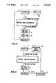
- the basic radar measurement situationis shown in FIG. 1.
- the distance dcan be determined from (3) because the microwave velocity in air is constant (the velocity of light) and the transit time t is measured.
- Different techniques to measure the distance by measuring the microwave transit time or the relative changes of itare well documented e.g. in Skolnik, M. I.:Introduction to Radar Systems, 2nd Ed., New York. MacGraw-Hill 1980/.
- the transit timeis given as earlier stated by formula (2), because the microwave velocity in the material is decreased by an amount determined by the relative dielectric constant of the material.
- the microwave velocity in radar casenow distance travelled by microwave in the material is constant and the microwave velocity changes as a function of the relative dielectric constant of the measured material.
- the dielectric constant of wateris large compared with most other materials and thus the relative dielectric constant of the material (and with it the microwave velocity and the transit time through the material) changes as the moisture content of the material changes. This interdependence between the microwave velocity (or its relative changes) and the moisture content of the material can be measured with the method of the invention.
- the change in the velocity of the microwave signalis determined by measuring the transit time of the microwave pulse, burst or pulse sequence, which has travelled through the material in a constant measuring gap.
- the transit timeis measured directly, using a clock or clocks, as the time interval between the transmitted and the received microwave pulse, burst or pulse sequence.
- FIG. 3The basic configuration of this kind of measurement system is shown in FIG. 3., where a microwave pulse, pulse sequence or a narrow band microwave burst is produced and/or modulated and transmitted through the material at the measuring gap and received at the receiver.
- the transmitted pulse, pulses or burststarts and the received pulse, pulses or burst stops the clock or the clocks.
- the changes in microwave velocity in the material under measurementcan be measured, and the moisture content of the material can be determined on the basis of a known interdependence between the moisture content and the velocity changes in material.
- the basic resolution of the transit time measurementis determined by the oscillator frequencies of the clock or clocks and their stability and the slew rates and the repeatabilities of the transmitted and received pulses, to which the clock start and stop signals are triggered.
- shorter pulsesrequire a broader bandwidth and thus the received energy is smaller; therefore bursts and compressed pulses (chirps) are often used. /Skolnik M. I. . . . /.
- Another techniqueis to use impulse radar technique, where an extremely short pulse is transmitted and the received signal is sampled only once for each transmitted pulse. By changing the time interval between the transmission and sampling, the whole received signal is gradually reconstructed. Thus an improvement of 1/ ⁇ n on the signal to noise ratio of the received signal can be achieved (n is the amount of the samples).
- nis the amount of the samples.
- the unstability of the measurement situationrestricts the amount of the collected samples; if the velocity in the material changes rapidly and/or the dynamics of the velocity changes is wide, the error caused by the velocity changes during the sampling sequences will lead to inaccurate measurement results.
- the transit time measurement resolution of the clock systemcan further be improved with digital interpolation techniques where two or more stable oscillators are used (e.g. vernier or dual vernier methods), or analog interpolation techniques using e.g. charging and decharging of capacitors /Kostamovaara J., Myllyla R. Atime-to-Amplitude Converter with Constant Fraction Timing discriminators for Short Time Interval Measurements, Nucl. Instr. and Methods in Physics Research, A239, North-Holland, Amsterdam, 1985, pp 568-578./
- the accuracy of the triggering of the start and stop signals to the rising edge of the pulse or the burst envelopecan be improved by using techniques where the signals are triggered at the moment the pulse signal (or the burst envelope) reaches a predetermined constant fraction of its maximum amplitude/Kostamovaara J. et al . . . /.
- the transmitter and the receiverare arranged on different sides relative to the material under measurement.
- the transmitter and the receiverare on the same side relative to the material to be measured and a reflector plate is provided on the opposite side to reflect the microwave signal proceeding from the transmitter to pass it to the receiver after it has travelled through the material.
- the transit time of a continuous or intermittent pulse-type or pulse-sequence type microwave signal which has travelled through the material to be measuredis determined by using correlation techniques, i.e. by transmitting wide-band noise or by modulating the microwave signal with random noise or random or pseudo random digital signals, and determining the transit time by the aid of the cross correlation function of the transmitted and the received signals.
- the observation timeshould be infinite, but in practice a relatively short period is enough to achieve the accuracy needed in transit time measurement. This allows also the use of pseudo noise in the measurement: the noise sequence shall only be longer than the observation time for each single measurement result.
- the transit time through the measured materialcan be determined from the cross correlation function as the delay value ⁇ m on which the cross correlation function reaches its maximum value /Bendat J. S., Piersol A. G.: Random Data: Analysis and Measurement Procedures, Wiley-Interscience, New York, 1971./
- the main elements of the correlation measurement systemare shown in FIG. 4, where the modulator modulates according to a random or pseudo random sequence the amplitude and/or phase of the transmitted continuous or intermittent signal or the amplitude of transmitted pulses and/or the time intervals between transmitted pulses. It's also possible to use random or pseudo random noise as the transmitted signal and then no special modulator is needed.
- the received signalis amplified with a low-noise amplifier and demodulated (if needed) in the detection section.
- the cross correlation function (and the delay giving the maximum, i.e. the transit time through the material) of the transmitted modulation or noise and the detected modulation or noiseis calculated at the correlator unit.
- the velocity changes in the materialcan be determined as earlier stated by formula (4) and the moisture of the material under measurement can be determined on the basis of a known interdependence between moisture content of the material and the velocity changes in the material.
- the change occurring in the velocity of the microwave signal when travelling through the material to be measuredis determined with the aid of frequency modulation, whereby a microwave signal is produced, the frequency of the microwave signal is varied in accordance with a mathematical function from the lower limit f 1 to the upper limit f 2 of its frequency range and/or vice versa within a certain period of time T, the microwave signal is divided into a first component and a second component, the first component is transmitted through the material at the measuring point, the first component which has travelled through the material is mixed with the second component, an intermediate frequency signal ⁇ f corresponding to the delay is formed from the mixed signal thus obtained, and the moisture content of the material under measurement is determined from the signal ⁇ f on the basis of a known interdependence between the moisture content and the intermediate frequency signal ⁇ f.
- the intermediate frequency ⁇ fcan also be calculated as follows:
- Table 1shows typical intermediate frequency ⁇ f values for certain materials as obtained from the formula (6).
- the dielectric constant for wateris high in comparison with the dielectric constants of the other materials. Therefore, the intermediate frequency is higher in the case of wet wood than in the case of dry wood.
- the moisture content of a given materialis determined from the frequency of the intermediate frequency signal ⁇ f either via calculation or by graphical means, provided that the interrelation between the moisture content of the material and the frequency of the intermediate frequency signal is known.
- This interrelationcan be determined by performing several measurements using the method and apparatus of the invention on a material whose moisture content is known or is to be measured. Based on the measurement results, a function describing the interdependence of the two quantities is formed. This function is then utilized in measurements performed using the method and apparatus of the invention to determine or calculate the moisture content of materials.
- the interdependence functioncan be included in a computer program which computes the final value of the moisture content.
- the frequency of the microwave signalis varied continuously and cyclically from the lower frequency f 1 to the upper frequency f 2 and then from the upper frequency f 2 to the lower frequency f 1 .
- the material to be measuredconsists of a stream of material such as wood chips, pulp fibers or a water suspension, e.g. chemical or mechanical wood pulp, which is passed through a measuring gap.
- the determination of the moisture contentis implemented as a continuous measuring process.
- the apparatus of the inventioncomprises a transmitting device which transmits a microwave signal through the material to be measured, and a detecting device and a counting device which measure the change of velocity of the signal transmitted through the material and determine the moisture content of the material on the basis of a known interdependence of the change of velocity of the microwave signal in question and change of moisture content of the material.
- the transmitting devicecomprises an oscillator designed to produce a signal of a frequency in the microwave range and to vary the signal frequency from a lower frequency f 1 to an upper frequency f 2 and/or vice versa within a given period of time T in accordance with a mathematical function, an isolator designed to pass the signal in the oscillator circuit in only one direction, a directional coupler designed to divide the signal into a first component and a second component, and a transmitter (e.g. a transmitting antenna) designed to transmit the first signal component obtained from the directional coupler through the material to be measured;
- the detecting devicecomprises a receiver (e.g.
- a receiving antennadesigned to receive the first signal component after it has travelled through the material to be measured
- a mixerprovided with a first input gate, a second input gate and an output gate and designed to receive the first component from the receiver via its first input gate and the second component directly from the directional coupler via its second input gate and to mix the signals applied to the input gates, to produce from the signal thus formed an intermediate frequency signal corresponding to the delay and to output it through the output gate;
- the counting deviceis designed to control the oscillator and to measure the frequency of the intermediate frequency signal obtained from the mixer output gate and to determine the moisture content value of the material under measurement from the intermediate frequency signal on the basis of a known interdependence of said signal and the moisture content.
- the transmitter and the receiverare arranged on different sides relative to the material under measurement.
- the transmitter and the receiverare on the same side relative to the material to be measured and a reflector plate is provided on the opposite side to reflect the microwave signal proceeding from the transmitter to pass it to the receiver after it has travelled through the material.
- the counting deviceis designed to control the oscillator in such a way that the frequency of the microwave signal is continuously varied from the lower frequency f 1 to the upper frequency f 2 and then from the upper frequency f 2 to the lower frequency f 1 .
- the apparatusis provided with a first electric cable, a second electric cable and a third electric cable, of which the first electric cable conducts the microwave signal from the directional coupler to the second input gate of the mixer, the second electric cable conducts the signal from the directional coupler to the transmitter and the third electric cable conducts the signal from the receiver to the first input gate of the mixer, the lengths of the first, second and third electric cables being so chosen that the frequency of the intermediate frequency signal will be in a range that is technically easy to measure.
- the frequency of the intermediate frequency signalcan also be adjusted to the desired level by altering the sweep width (B), the sweep time (T) or the distance (d) travelled by the microwave in the material under measurement.
- FM-CWmicrowave frequency modulation
- the microwave frequency modulation techniquecan be employed in a completely new area of application, i.e. measurement of the moisture content of a material, where it has never been applied before.
- the embodiment of the inventionmakes it possible to utilize all the advantages of the FM-CW technique in connection with the measurement of the moisture content of materials.
- a further advantage of the inventionis that the output signal to be measured permits easy processing or consists of a burst signal, the measurement of whose frequency is simple and easy and does not necessarily impose very high requirements on the electronics used in the apparatus.
- FIG. 1illustrates a basic radar measurement setup
- FIG. 2illustrates the basic measurement set up for a first embodiment of the method of the invention
- FIG. 3illustrates the basic measurement set up for a second embodiment of the method of the invention, i.e. the transit time measurement setup,
- FIG. 4illustrates the basic measurement set up for a third embodiment of the method of the invention, i.e. the correlation based measurement setup,
- FIG. 5illustrates the basic measurement set up for a third embodiment of the method of the invention, i.e. measurement setup employing microwave frequency modulation (FM-CW) technique,
- FM-CWmicrowave frequency modulation
- FIG. 6ashows the oscillator frequency and the mixer output signal of the apparatus in FIG. 5 as function of time
- FIG. 6bshows the intermediate frequency ⁇ f of FIG. 6a as function of time
- FIG. 7shows a detail of a third embodiment of the apparatus of the invention
- FIG. 8shows an example of measurement results and a function determined from these results to determine the known interdependence between the intermediate frequency and the moisture of the wood chips
- FIG. 9shows an example of measurement results and a function determined from these results to determine the known interdependence between the intermediate frequency and the moisture of the pine pulp.
- FIG. 1illustrates a known basic radar measurement setup already disclosed above.
- FIG. 2there is shown a basic measurement setup of the method of the invention.
- the systemtransmits a microwave signal through the material under measurement in a constant measuring gap d, whereupon it measures the change of velocity of the signal which has passed through the material and determines the moisture content of the material on the basis of a predetermined known interdependence between the change of velocity of the microwave signal in question and the change of moisture content of the material.
- the apparatuscomprises a transmitting device 1, a detecting device 2 and a counting device 3.
- the transmitter 1 and the receiver 2are here arranged on different sides relative to the material under measurement.
- the measurement of the change of velocitycan be based on the transit time or noise correlation of a microwave pulse, burst or pulse sequence or frequency modulation.
- FIG. 3there is shown the basic configuration of the measurement system, in which the change in the velocity of the microwave signal is determined by measuring the transit time of the microwave pulse, burst or pulse sequence, which has travelled through the material in a constant measuring gap d.
- the transit timeis measured directly, using at least one clock, as a time interval between the transmitted and the received microwave pulse, burst or pulse sequence.
- a microwave pulse, pulse sequence or a narrow band microwave burstis first produced and/or modulated by transmitter 1 and/or modulator 14.
- Microwave pulse, burst or pulse sequenceis transmitted by transmitting antenna 15 through the material and is received by the receiving antenna 16.
- the transmitted pulse, burst or pulse sequencestarts the clock device 17 and the received and the received pulse, pulses or burst stops the clock device.
- the measurement setupfurther comprises a low-noise amplifier 18 for amplifying the signal, and a detection device 19.
- the microwave velocity (v)can be calculated from formula (4) stated above, when the distance (d) of the constant measuring gap is known.
- the changes in microwave velocity in the materialcan be measured and the moisture content of the material can be determined on the basis of a known interdependence between the moisture content of the material and the velocity changes.
- FIG. 4there are shown the main elements of the correlation measurement system for conducting a method, wherein the transit time of a continuous or intermittent pulse-type or pulse-sequence type microwave signal which has travelled through the material to be measured is determined by using correlation techniques, i.e. by transmitting wide-band noise or by modulating the microwave signal with random noise or random pseudo random digital signals, and determining the transit time by the aid of the cross correlation function of the transmitted and the received signals.
- the modulator 20modulates according to a random or pseudo random sequence the amplitude and/or phase of the transmitted continuous or intermittent signal or the amplitude of transmitted pulses and/or the time intervals between transmitted pulses. It's also possible to use random or pseudo random noise as the transmitted signal and then no special modulator is needed.
- the received signalis amplified with a low-noise amplifier 21 and demodulated (if needed) in the detection section 22.
- the cross correlation function (and the delay giving the maximum, i.e. the transit time through the material) of the transmitted modulation or noise and the detected modulation or noiseis calculated at the correlator unit 23.
- the velocity changes in the materialcan be determined as earlier stated in formula (4) and the moisture of the material under measurement can be determined on the basis of a known interdependence between moisture content of the material and the velocity changes in the material.
- a microwave signalis transmitted through the material, whereupon, using frequency modulation, the system measures the change of velocity of the signal which has passed through the material and determines the moisture content of the material on the basis of a known interdependence between the change of velocity of the microwave signal and the change of moisture content of the material.
- the apparatuscomprises a transmitting device 1, a detecting device 2 and a counting device 3.
- the transmitting device 1consists of an oscillator 4, an isolator 5, a directional coupler 6 and a transmitter 7.
- the detecting device 2consists of a receiver 8 and a mixer 9.
- the oscillator 4produces a microwave-frequency signal. Controlled by the counter 3, the oscillator changes the signal frequency in a linear fashion through a certain range of frequencies within a certain period of time. Thereupon the signal frequency is again changed linearly from the upper limit of the range to its lower limit. These cyclic variations are continued without interruption.
- the isolator 5takes care that the microwave signal is only allowed to travel in one direction in the oscillating circuit.
- the directional coupler 6divides the microwave signal into a first component I and a second component II.
- the first component I of the microwave signalis passed via the second electric cable 12 to the transmitter 7.
- the transmitter 7transmits the signal through the material under measurement.
- the receiver 8receives the microwave signal I which has travelled through the material under measurement.
- the transmitter and the receiverare placed on opposite sides of the material. On its way through the material, the signal I is retarded and delayed as compared to the second microwave signal component II, which is used as a reference quantity in the mixer 9.
- the mixercomprises a first input gate RF, a second input gate LO and an output gate IF.
- the second input gate LO of the mixeris fed by the second signal component II, which is supplied directly from the directional coupler via cable 11.
- the first input gate RF of the mixer 9is fed by the first signal component I, supplied by the receiver via cable 13.
- the mixerIn the mixer, the signals I and II applied to its input gates RF and LO are mixed. From the signal thus obtained, the mixer produces an intermediate frequency signal ⁇ f, which is obtained from the output gate IF.
- the intermediate frequency signal ⁇ f corresponding to the delayis adjusted to a level allowing technically easy measurement.
- the counting device 3measures the frequency of the intermediate frequency signal ⁇ f obtained from the output gate IF of the mixer.
- the moisture content value of the material under measurementcan be determined from this frequency on the basis of a known interdependence between the intermediate frequency signal ⁇ f and the moisture content. For a given material, this interdependence being known, the moisture content value is obtained either by calculation or by graphical means.
- the interdependencecan be determined by performing several measurements with the method and apparatus of the invention on a material with known moisture content values. Based on the measurement results, a function describing the interdependence of the quantities is formed. This function is then utilized in the computation of the moisture content value of materials in measurements performed with the method and apparatus of the invention.
- FIG. 6ashows a graph representing the frequency of the microwave signals at the first input gate RF and at the second input gate LO of the mixer 9.
- the signal frequencychanges from a lower frequency f 1 to a higher frequency f 2 during a period of time T, the slope of the change being constant.
- the signal I applied to the first input gate RF of the mixeris delayed by a length of time ⁇ as compared to the signal II applied to the second input gate LO.
- the continuous linerepresents the signal II at the second input gate LO while the broken line represents the signal I at the first input gate RF.
- the time difference ⁇arises from the fact that the microwave signal is delayed on its way from the transmitter 7 to the receiver 8. From signals I and II, the mixer produces an intermediate frequency signal ⁇ f, which is proportional to the moisture content of the material under measurement.
- the curve in FIG. 6brepresents the amplitude of the intermediate frequency signal ⁇ f as a function of time.
- FIG. 7shows an embodiment in which the transmitter 7 and the receiver 8 are placed on the same side of the material under measurement, with a reflector plate 10 provided on the opposite side.
- the platereflects the microwave signal transmitted by the transmitter 7 to the receiver 8.
- FIG. 8presents the results of measurements on wood chips. These measurements were performed by the method of the invention to determine the interdependence between the moisture content and the frequency of the intermediate frequency signal.
- the measurementswere performed on wood chips with six different known moisture content values, so that the corresponding six frequencies of the intermediate frequency signal ⁇ f were obtained. Because the moisture content of wood chips was desired to be expressed in terms of percentages by weight at each measuring point, the frequency values were divided by the density of the sample under measurement, whereby the effects of different densities on the results were eliminated.
- the measurement results and the interdependence function obtained from themare presented in the form of a graph.
- the vertical axisrepresents the frequency of the intermediate frequency signal ⁇ f divided by the density of the material under measurement.
- the horizontal axisrepresents the moisture content of the wood chips in terms of percentages by weight.
- FIG. 9presents the results of measurements on pine pulp. These measurements were performed by an embodiment of the method of the invention to determine the interdependence between the moisture content and the frequency of the intermediate frequency signal.
- the measurementswere performed on pine pulp with nine different known moisture content values, so that the corresponding nine frequencies of the intermediate frequency signal ⁇ f were obtained.
- the moisture content of pine pulpis expressed in terms of percentages by weight at each measuring point.
- FIG. 9the measurement results and the interdependence function obtained from them are presented in the form of a graph.
- the vertical axisrepresents the frequency of the intermediate frequency signal ⁇ f.
- the horizontal axisrepresents the moisture content of the pine pulp in terms of percentages by weight.
- Table 1discloses the class on magnitude relating to solid wood and is therefore not comparable with the results of FIGS. 8 and measured on wood chips and pine pulp.
Landscapes
- Physics & Mathematics (AREA)
- Electromagnetism (AREA)
- Health & Medical Sciences (AREA)
- Life Sciences & Earth Sciences (AREA)
- Chemical & Material Sciences (AREA)
- Analytical Chemistry (AREA)
- Biochemistry (AREA)
- General Health & Medical Sciences (AREA)
- General Physics & Mathematics (AREA)
- Immunology (AREA)
- Pathology (AREA)
- Investigating Or Analyzing Materials By The Use Of Ultrasonic Waves (AREA)
Abstract
Description
t=2d/c (3)
v=d/t (4)
Δf=B·d·((ε.sub.r '+|ε.sub.r |)/2)1/2/(T·c) (6)
TABLE 1 ______________________________________ Calculated Δf values for different materials. Material ε.sub.r ' ε.sub.r " Δf (Hz) ______________________________________ Water 80 5 1788Wet wood 23 2.5 959Dry wood 3 0.1 346Air 1 0 200 ______________________________________
Claims (7)
Priority Applications (1)
| Application Number | Priority Date | Filing Date | Title |
|---|---|---|---|
| US07/859,893US5315258A (en) | 1989-01-13 | 1992-03-30 | Method and apparatus for determining the moisture content of a material |
Applications Claiming Priority (4)
| Application Number | Priority Date | Filing Date | Title |
|---|---|---|---|
| FI890201 | 1989-01-13 | ||
| FI890201AFI84402C (en) | 1989-01-13 | 1989-01-13 | Method and apparatus for determining moisture content of the material |
| US46428190A | 1990-01-12 | 1990-01-12 | |
| US07/859,893US5315258A (en) | 1989-01-13 | 1992-03-30 | Method and apparatus for determining the moisture content of a material |
Related Parent Applications (1)
| Application Number | Title | Priority Date | Filing Date |
|---|---|---|---|
| US46428190AContinuation-In-Part | 1989-01-13 | 1990-01-12 |
Publications (1)
| Publication Number | Publication Date |
|---|---|
| US5315258Atrue US5315258A (en) | 1994-05-24 |
Family
ID=26158488
Family Applications (1)
| Application Number | Title | Priority Date | Filing Date |
|---|---|---|---|
| US07/859,893Expired - LifetimeUS5315258A (en) | 1989-01-13 | 1992-03-30 | Method and apparatus for determining the moisture content of a material |
Country Status (1)
| Country | Link |
|---|---|
| US (1) | US5315258A (en) |
Cited By (28)
| Publication number | Priority date | Publication date | Assignee | Title |
|---|---|---|---|---|
| WO1998044339A1 (en)* | 1997-03-27 | 1998-10-08 | Valmet Automation Inc. | Method and arrangement for measuring and controlling consistency |
| US5869747A (en)* | 1996-05-22 | 1999-02-09 | William H. Hulsman | Food container internal pressure analysis |
| WO2001092861A3 (en)* | 2000-05-30 | 2002-08-08 | Esi Environmental Sensors Inc | Oil/water sensor based on time domain transmission (tdt) |
| DE10128131A1 (en)* | 2001-06-09 | 2002-12-12 | Lutz Berger | Inspection or identification of test objects by irradiation of an object with microwaves and evaluation of radiation reflected from the test object and has passed through the object and been reflected from a rotating reflector |
| EP0935136A3 (en)* | 1998-01-09 | 2003-03-05 | Malcam Ltd. | Device and method for determining the moisture content of a bulk material |
| WO2003019207A1 (en) | 2001-08-24 | 2003-03-06 | Rhino Analytics, L.L.C. | Ultra-wide band pulse dispersion spectrometry method and apparatus providing multi-component composition analysis |
| US20030076120A1 (en)* | 2001-09-28 | 2003-04-24 | Dehart Scott Alan | System and method for measuring moisture content in a conductive environment |
| US20030226397A1 (en)* | 2002-06-10 | 2003-12-11 | Sherman Faiz Feisal | Directional coupler sensor |
| US6784671B2 (en) | 2002-02-04 | 2004-08-31 | Mississippi State University | Moisture and density detector (MDD) |
| US20040239338A1 (en)* | 2001-05-31 | 2004-12-02 | Jonsson Olafur H. | Apparatus and method for microwave determination of least one physical parameter of a substance |
| US20040243326A1 (en)* | 2003-05-30 | 2004-12-02 | Daoud Bassel H. | Method and apparatus for measuring the transmission loss of a cable |
| US20050238793A1 (en)* | 2004-04-26 | 2005-10-27 | Sherman Faiz F | Methods of assessing characteristics of fibrous substrates and treating fibrous substrates |
| US20050253595A1 (en)* | 2002-09-26 | 2005-11-17 | France Garry G | Analysis of variable-depth sample using a sweeping microwave signal |
| US20060028213A1 (en)* | 2004-08-06 | 2006-02-09 | Voith Paper Patent Gmbh | Microwave water weight sensor and process |
| US20060208194A1 (en)* | 2005-03-18 | 2006-09-21 | Voith Paper Patent Gmbh | Microwave mass measuring device and process |
| US20080007273A1 (en)* | 2006-06-30 | 2008-01-10 | Sherman Faiz F | Device for measuring moisture in substrate and health of hair |
| US20080211516A1 (en)* | 2005-05-17 | 2008-09-04 | Elektrobit Microwave Oy | Method and Measuring Instrument for Measuring Water Content |
| EP2101170A1 (en)* | 2008-03-11 | 2009-09-16 | Nederlandse Centrale Organisatie Voor Toegepast Natuurwetenschappelijk Onderzoek TNO | Method, system and computer program for contactless measuring a moisture percentage |
| WO2009146881A3 (en)* | 2008-06-02 | 2010-01-28 | Rohde & Schwarz Gmbh & Co. Kg | Breast cancer detection device having a fixing cone |
| US20120074958A1 (en)* | 2010-09-28 | 2012-03-29 | Hauni Maschinenbau Ag | Device and method for processing and measuring properties of a moving rod of material |
| US20150022220A1 (en)* | 2013-07-22 | 2015-01-22 | Honeywell Asca Inc. | Multi-frequency Microwave Sensor for Temperature Independent Measurement of Moisture |
| CN105510386A (en)* | 2014-09-26 | 2016-04-20 | 多瑙控制治理工程有限责任公司 | Radio frequency measurement system for measuring water content of paper and various fiber-containing materials |
| US20170279596A1 (en)* | 2013-09-13 | 2017-09-28 | Inside Secure | Method and device for transmitting data by inductive coupling with controlled self-oscillation |
| US10422742B2 (en)* | 2017-10-18 | 2019-09-24 | The Boeing Company | Moisture detection system |
| US10656081B2 (en) | 2017-10-18 | 2020-05-19 | The Boeing Company | Synchronized phased array and infrared detector system for moisture detection |
| US20230046857A1 (en)* | 2021-08-14 | 2023-02-16 | Kamal Mahajan | System and method for measuring a physical parameter in a gaseous sample |
| EP4141424A4 (en)* | 2020-04-20 | 2023-10-18 | Sony Group Corporation | Detection device and detection method |
| EP4365579A1 (en)* | 2022-11-07 | 2024-05-08 | Valmet Automation Oy | Apparatus for and method of measuring moving web |
Citations (12)
| Publication number | Priority date | Publication date | Assignee | Title |
|---|---|---|---|---|
| US3599088A (en)* | 1967-10-31 | 1971-08-10 | Beloit Corp | Microwave moisture sensing system including means to continuously change the transmission path of the microwave energy |
| DE2239848A1 (en)* | 1972-08-12 | 1974-02-21 | Bayer Ag | MICROWAVE TRANSMISSION ARRANGEMENT FOR MEASURING THE WATER CONTENT |
| US3851244A (en)* | 1973-12-18 | 1974-11-26 | Electronic Ass Of Canada Ltd | Microwave moisture measuring apparatus |
| US4123702A (en)* | 1976-02-13 | 1978-10-31 | Ilmari Kinanen | Method for classifying and measuring of timbers |
| US4135131A (en)* | 1977-10-14 | 1979-01-16 | The United States Of America As Represented By The Secretary Of The Army | Microwave time delay spectroscopic methods and apparatus for remote interrogation of biological targets |
| US4155035A (en)* | 1975-11-26 | 1979-05-15 | Bayer Aktiengesellschaft | Device for the measurement of the moisture content of a sample |
| US4297874A (en)* | 1979-10-26 | 1981-11-03 | Shinichi Sasaki | Apparatus for measuring a percentage of moisture and weighing of a sheet-like object |
| CA1130863A (en)* | 1979-06-22 | 1982-08-31 | Neilson A.M. Mackay | Measurement of soil moisture |
| US4361801A (en)* | 1979-07-14 | 1982-11-30 | U.S. Philips Corporation | Microwave method for measuring the relative moisture content of an object |
| US4546311A (en)* | 1981-12-18 | 1985-10-08 | U.S. Philips Corporation | Arrangement for measuring moisture content |
| US4675595A (en)* | 1984-06-27 | 1987-06-23 | Stiftesen Institutet for Microvagsteknik | Method for measuring the moisture ratio of organic material, and apparatus herefor |
| US4727311A (en)* | 1986-03-06 | 1988-02-23 | Walker Charles W E | Microwave moisture measurement using two microwave signals of different frequency and phase shift determination |
- 1992
- 1992-03-30USUS07/859,893patent/US5315258A/ennot_activeExpired - Lifetime
Patent Citations (12)
| Publication number | Priority date | Publication date | Assignee | Title |
|---|---|---|---|---|
| US3599088A (en)* | 1967-10-31 | 1971-08-10 | Beloit Corp | Microwave moisture sensing system including means to continuously change the transmission path of the microwave energy |
| DE2239848A1 (en)* | 1972-08-12 | 1974-02-21 | Bayer Ag | MICROWAVE TRANSMISSION ARRANGEMENT FOR MEASURING THE WATER CONTENT |
| US3851244A (en)* | 1973-12-18 | 1974-11-26 | Electronic Ass Of Canada Ltd | Microwave moisture measuring apparatus |
| US4155035A (en)* | 1975-11-26 | 1979-05-15 | Bayer Aktiengesellschaft | Device for the measurement of the moisture content of a sample |
| US4123702A (en)* | 1976-02-13 | 1978-10-31 | Ilmari Kinanen | Method for classifying and measuring of timbers |
| US4135131A (en)* | 1977-10-14 | 1979-01-16 | The United States Of America As Represented By The Secretary Of The Army | Microwave time delay spectroscopic methods and apparatus for remote interrogation of biological targets |
| CA1130863A (en)* | 1979-06-22 | 1982-08-31 | Neilson A.M. Mackay | Measurement of soil moisture |
| US4361801A (en)* | 1979-07-14 | 1982-11-30 | U.S. Philips Corporation | Microwave method for measuring the relative moisture content of an object |
| US4297874A (en)* | 1979-10-26 | 1981-11-03 | Shinichi Sasaki | Apparatus for measuring a percentage of moisture and weighing of a sheet-like object |
| US4546311A (en)* | 1981-12-18 | 1985-10-08 | U.S. Philips Corporation | Arrangement for measuring moisture content |
| US4675595A (en)* | 1984-06-27 | 1987-06-23 | Stiftesen Institutet for Microvagsteknik | Method for measuring the moisture ratio of organic material, and apparatus herefor |
| US4727311A (en)* | 1986-03-06 | 1988-02-23 | Walker Charles W E | Microwave moisture measurement using two microwave signals of different frequency and phase shift determination |
Non-Patent Citations (2)
| Title |
|---|
| Skol Nik: Introduction To Radar Systems McGraw Hill 1980 pp. 81 85 (no month).* |
| Skol-Nik: "Introduction To Radar Systems"-McGraw Hill--1980--pp. 81-85 (no month). |
Cited By (52)
| Publication number | Priority date | Publication date | Assignee | Title |
|---|---|---|---|---|
| US5869747A (en)* | 1996-05-22 | 1999-02-09 | William H. Hulsman | Food container internal pressure analysis |
| WO1998044339A1 (en)* | 1997-03-27 | 1998-10-08 | Valmet Automation Inc. | Method and arrangement for measuring and controlling consistency |
| EP0935136A3 (en)* | 1998-01-09 | 2003-03-05 | Malcam Ltd. | Device and method for determining the moisture content of a bulk material |
| WO2001092861A3 (en)* | 2000-05-30 | 2002-08-08 | Esi Environmental Sensors Inc | Oil/water sensor based on time domain transmission (tdt) |
| US6707307B1 (en) | 2000-05-30 | 2004-03-16 | Esi Environmental Sensors Inc. | Fluid sensor |
| US7187183B2 (en)* | 2001-05-31 | 2007-03-06 | Intelscan Orbylgjutaekni Enf. | Apparatus and method for microwave determination of at least one physical parameter of a substance |
| US20040239338A1 (en)* | 2001-05-31 | 2004-12-02 | Jonsson Olafur H. | Apparatus and method for microwave determination of least one physical parameter of a substance |
| DE10128131A1 (en)* | 2001-06-09 | 2002-12-12 | Lutz Berger | Inspection or identification of test objects by irradiation of an object with microwaves and evaluation of radiation reflected from the test object and has passed through the object and been reflected from a rotating reflector |
| US7221169B2 (en) | 2001-08-24 | 2007-05-22 | Rhino Analytics, L.P. | Ultra-wide band pulse dispersion spectrometry method and apparatus providing multi-component composition analysis |
| WO2003019207A1 (en) | 2001-08-24 | 2003-03-06 | Rhino Analytics, L.L.C. | Ultra-wide band pulse dispersion spectrometry method and apparatus providing multi-component composition analysis |
| US20060091894A1 (en)* | 2001-08-24 | 2006-05-04 | Jean Buford R | Ultra-wide band pulse dispersion spectrometry method and apparatus providing multi-component composition analysis |
| EP1428033A4 (en)* | 2001-08-24 | 2006-08-02 | Rhino Analytics Llc | Ultra-wide band pulse dispersion spectrometry method and apparatus providing multi-component composition analysis |
| US6798215B2 (en)* | 2001-09-28 | 2004-09-28 | Baseline, Llc | System and method for measuring moisture content in a conductive environment |
| US20030076120A1 (en)* | 2001-09-28 | 2003-04-24 | Dehart Scott Alan | System and method for measuring moisture content in a conductive environment |
| EP1481255A4 (en)* | 2002-02-04 | 2005-02-09 | Univ Mississippi | MOISTURE AND DENSITY DETECTOR |
| US20050040832A1 (en)* | 2002-02-04 | 2005-02-24 | Steele Philip H. | Moisture and density detector (MDD) |
| US7068050B2 (en) | 2002-02-04 | 2006-06-27 | Mississippi State University | Moisture and density detector (MDD) |
| US6784671B2 (en) | 2002-02-04 | 2004-08-31 | Mississippi State University | Moisture and density detector (MDD) |
| US6854322B2 (en)* | 2002-06-10 | 2005-02-15 | The Procter & Gamble Company | Directional coupler sensor |
| CN100456027C (en)* | 2002-06-10 | 2009-01-28 | 宝洁公司 | Directional coupling sensor for measuring moisture content of hair |
| US20050120779A1 (en)* | 2002-06-10 | 2005-06-09 | The Procter & Gamble Company | Directional coupler sensor |
| US20030226397A1 (en)* | 2002-06-10 | 2003-12-11 | Sherman Faiz Feisal | Directional coupler sensor |
| US7190176B2 (en)* | 2002-09-26 | 2007-03-13 | Callidan Instruments Pty Ltd | Analysis of variable-depth sample using a sweeping microwave signal |
| US20050253595A1 (en)* | 2002-09-26 | 2005-11-17 | France Garry G | Analysis of variable-depth sample using a sweeping microwave signal |
| US20070069740A1 (en)* | 2002-09-26 | 2007-03-29 | Callidan Holdings Limited | Analysis of Variable-Depth Sample Using a Sweeping Microwave Signal |
| US6879918B2 (en)* | 2003-05-30 | 2005-04-12 | Lucent Technologies Inc. | Method and apparatus for measuring the transmission loss of a cable |
| US20040243326A1 (en)* | 2003-05-30 | 2004-12-02 | Daoud Bassel H. | Method and apparatus for measuring the transmission loss of a cable |
| US20050238793A1 (en)* | 2004-04-26 | 2005-10-27 | Sherman Faiz F | Methods of assessing characteristics of fibrous substrates and treating fibrous substrates |
| US7261000B2 (en)* | 2004-04-26 | 2007-08-28 | The Procter & Gamble Company | Methods of assessing characteristics of fibrous substrates and treating fibrous substrates |
| US20060028213A1 (en)* | 2004-08-06 | 2006-02-09 | Voith Paper Patent Gmbh | Microwave water weight sensor and process |
| US7151380B2 (en)* | 2004-08-06 | 2006-12-19 | Voith Paper Patent Gmbh | Microwave water weight sensor and process |
| US20060208194A1 (en)* | 2005-03-18 | 2006-09-21 | Voith Paper Patent Gmbh | Microwave mass measuring device and process |
| US8188751B2 (en) | 2005-05-17 | 2012-05-29 | Senfit Oy | Method and measuring instrument for measuring water content |
| US20080211516A1 (en)* | 2005-05-17 | 2008-09-04 | Elektrobit Microwave Oy | Method and Measuring Instrument for Measuring Water Content |
| US7928739B2 (en) | 2006-06-30 | 2011-04-19 | The Procter & Gamble Company | Device for measuring moisture in substrate and health of hair |
| US20080007273A1 (en)* | 2006-06-30 | 2008-01-10 | Sherman Faiz F | Device for measuring moisture in substrate and health of hair |
| EP2101170A1 (en)* | 2008-03-11 | 2009-09-16 | Nederlandse Centrale Organisatie Voor Toegepast Natuurwetenschappelijk Onderzoek TNO | Method, system and computer program for contactless measuring a moisture percentage |
| WO2009113857A1 (en)* | 2008-03-11 | 2009-09-17 | Nederlandse Organisatie Voor Toegepast-Natuurwetenschappelijk Onderzoek Tno | Method, system and computer program for contactless measuring a moisture percentage |
| WO2009146881A3 (en)* | 2008-06-02 | 2010-01-28 | Rohde & Schwarz Gmbh & Co. Kg | Breast cancer detection device having a fixing cone |
| US20120074958A1 (en)* | 2010-09-28 | 2012-03-29 | Hauni Maschinenbau Ag | Device and method for processing and measuring properties of a moving rod of material |
| US8912805B2 (en)* | 2010-09-28 | 2014-12-16 | Hauni Maschinenbau Ag | Device and method for processing and measuring properties of a moving rod of material |
| US20150022220A1 (en)* | 2013-07-22 | 2015-01-22 | Honeywell Asca Inc. | Multi-frequency Microwave Sensor for Temperature Independent Measurement of Moisture |
| US9182360B2 (en)* | 2013-07-22 | 2015-11-10 | Honeywell Asca Inc. | Multi-frequency microwave sensor for temperature independent measurement of moisture |
| US10177900B2 (en)* | 2013-09-13 | 2019-01-08 | Inside Secure | Method and device for transmitting data by inductive coupling with controlled self-oscillation |
| US20170279596A1 (en)* | 2013-09-13 | 2017-09-28 | Inside Secure | Method and device for transmitting data by inductive coupling with controlled self-oscillation |
| CN105510386A (en)* | 2014-09-26 | 2016-04-20 | 多瑙控制治理工程有限责任公司 | Radio frequency measurement system for measuring water content of paper and various fiber-containing materials |
| US10422742B2 (en)* | 2017-10-18 | 2019-09-24 | The Boeing Company | Moisture detection system |
| US10656081B2 (en) | 2017-10-18 | 2020-05-19 | The Boeing Company | Synchronized phased array and infrared detector system for moisture detection |
| EP4141424A4 (en)* | 2020-04-20 | 2023-10-18 | Sony Group Corporation | Detection device and detection method |
| US12099020B2 (en) | 2020-04-20 | 2024-09-24 | Sony Group Corporation | Detection device and detection method |
| US20230046857A1 (en)* | 2021-08-14 | 2023-02-16 | Kamal Mahajan | System and method for measuring a physical parameter in a gaseous sample |
| EP4365579A1 (en)* | 2022-11-07 | 2024-05-08 | Valmet Automation Oy | Apparatus for and method of measuring moving web |
Similar Documents
| Publication | Publication Date | Title |
|---|---|---|
| US5315258A (en) | Method and apparatus for determining the moisture content of a material | |
| US5333493A (en) | Moisture content by microwave phase shift and mass/area | |
| CA1185658A (en) | Microwave meter for fluid mixtures | |
| US7823446B2 (en) | Pulsed radar level gauging with relative phase detection | |
| CA1332458C (en) | Distance and level measuring system | |
| US5233352A (en) | Level measurement using autocorrelation | |
| Webster | A pulsed ultrasonic distance measurement system based upon phase digitizing | |
| US4691204A (en) | Radar apparatus | |
| JP2005501262A (en) | Ultra-wideband pulse dispersion spectroscopic analysis method and multi-component composition analyzer | |
| AU2002323311A1 (en) | Ultra-wide band pulse dispersion spectrometry method and apparatus providing multi-component composition analysis | |
| CA2236109C (en) | Arrangement for measuring thickness of a medium | |
| CA2007300C (en) | Method and apparatus for determining the moisture content of a material | |
| US4341112A (en) | Measurement of soil moisture | |
| US20030185101A1 (en) | Method and apparatus for spread spectrum distance measurement and for spread spectrum velocity profile measurement | |
| Hagfors | Incoherent scatter radar observations of the plasma line with a chirped pulse system | |
| RU2410650C2 (en) | Method to measure level of material in reservoir | |
| EP0487582B1 (en) | Moisture content by microwave phase shift and mass/area | |
| RU2399888C1 (en) | Method of measuring level of material in reservoir | |
| Ruser et al. | Sweep linearization of a microwave FMCW Doppler sensor by an ultrasonic reference | |
| JPS5835478A (en) | Locating device for underground structure by radar system | |
| Killough et al. | Measuring the moisture content of wood sheathing with continuous wave radars | |
| JP3558492B2 (en) | Apparatus and method for measuring dry density of soil | |
| RU2805032C1 (en) | Radar method for monitoring concrete structures | |
| AU635313B2 (en) | Moisture content by microwave phase shift and mass/area | |
| JP3558491B2 (en) | Apparatus and method for transmitting and receiving pulsed signals into the ground |
Legal Events
| Date | Code | Title | Description |
|---|---|---|---|
| AS | Assignment | Owner name:KAJAANI ELEKTRONIIKKA OY, FINLAND Free format text:ASSIGNMENT OF ASSIGNORS INTEREST;ASSIGNORS:JAKKULA, PEKKA;TAHKOLA, ESKO;REEL/FRAME:006869/0396 Effective date:19920430 | |
| STCF | Information on status: patent grant | Free format text:PATENTED CASE | |
| FPAY | Fee payment | Year of fee payment:4 | |
| FEPP | Fee payment procedure | Free format text:PAYOR NUMBER ASSIGNED (ORIGINAL EVENT CODE: ASPN); ENTITY STATUS OF PATENT OWNER: LARGE ENTITY | |
| AS | Assignment | Owner name:METSO AUTOMATION OY, FINLAND Free format text:CHANGE OF NAME;ASSIGNOR:NELES AUTOMATION OY;REEL/FRAME:011862/0585 Effective date:19990618 Owner name:METSO FIELD SYSTEMS OY, FINLAND Free format text:ASSIGNMENT OF ASSIGNORS INTEREST;ASSIGNOR:METSO AUTOMATION OY;REEL/FRAME:011862/0845 Effective date:20010206 Owner name:VALMET AUTOMATION OY, FINLAND Free format text:MERGER;ASSIGNOR:VALMET AUTOMATION KAJAANI OY;REEL/FRAME:011862/0847 Effective date:19990618 Owner name:NELES AUTOMATION OY, FINLAND Free format text:MERGER;ASSIGNOR:VALMET AUTOMATION OY;REEL/FRAME:011862/0850 Effective date:19990618 Owner name:VALMET AUTOMATION KAJAANI OY, FINLAND Free format text:CHANGE OF NAME;ASSIGNOR:KAJAANI ELEKTRONIIKKA OY;REEL/FRAME:011862/0853 Effective date:19990618 | |
| FPAY | Fee payment | Year of fee payment:8 | |
| FEPP | Fee payment procedure | Free format text:PAYER NUMBER DE-ASSIGNED (ORIGINAL EVENT CODE: RMPN); ENTITY STATUS OF PATENT OWNER: LARGE ENTITY Free format text:PAYOR NUMBER ASSIGNED (ORIGINAL EVENT CODE: ASPN); ENTITY STATUS OF PATENT OWNER: LARGE ENTITY | |
| FPAY | Fee payment | Year of fee payment:12 |