US5314093A - Toggle-action dispensing closure with rotatable locking ring - Google Patents
Toggle-action dispensing closure with rotatable locking ringDownload PDFInfo
- Publication number
- US5314093A US5314093AUS07/951,871US95187192AUS5314093AUS 5314093 AUS5314093 AUS 5314093AUS 95187192 AUS95187192 AUS 95187192AUS 5314093 AUS5314093 AUS 5314093A
- Authority
- US
- United States
- Prior art keywords
- actuator
- actuator means
- closure
- ring
- engaging
- Prior art date
- Legal status (The legal status is an assumption and is not a legal conclusion. Google has not performed a legal analysis and makes no representation as to the accuracy of the status listed.)
- Expired - Fee Related
Links
- 230000004044responseEffects0.000claimsdescription5
- 238000007373indentationMethods0.000description10
- 230000002093peripheral effectEffects0.000description8
- 238000007789sealingMethods0.000description6
- 238000006073displacement reactionMethods0.000description4
- 230000006870functionEffects0.000description4
- 239000000463materialSubstances0.000description4
- 230000013011matingEffects0.000description4
- 230000002028prematureEffects0.000description4
- 230000008901benefitEffects0.000description3
- 210000003811fingerAnatomy0.000description3
- 230000009969flowable effectEffects0.000description3
- 239000011324beadSubstances0.000description2
- 230000000694effectsEffects0.000description2
- 230000009286beneficial effectEffects0.000description1
- 230000000903blocking effectEffects0.000description1
- 230000006872improvementEffects0.000description1
- 238000000034methodMethods0.000description1
- 230000004048modificationEffects0.000description1
- 238000012986modificationMethods0.000description1
- 238000000465mouldingMethods0.000description1
- 230000008569processEffects0.000description1
- 230000035807sensationEffects0.000description1
- 239000000126substanceSubstances0.000description1
- 239000012815thermoplastic materialSubstances0.000description1
- 210000003813thumbAnatomy0.000description1
- 230000000007visual effectEffects0.000description1
Images

Classifications
- B—PERFORMING OPERATIONS; TRANSPORTING
- B65—CONVEYING; PACKING; STORING; HANDLING THIN OR FILAMENTARY MATERIAL
- B65D—CONTAINERS FOR STORAGE OR TRANSPORT OF ARTICLES OR MATERIALS, e.g. BAGS, BARRELS, BOTTLES, BOXES, CANS, CARTONS, CRATES, DRUMS, JARS, TANKS, HOPPERS, FORWARDING CONTAINERS; ACCESSORIES, CLOSURES, OR FITTINGS THEREFOR; PACKAGING ELEMENTS; PACKAGES
- B65D50/00—Closures with means for discouraging unauthorised opening or removal thereof, with or without indicating means, e.g. child-proof closures
- B65D50/02—Closures with means for discouraging unauthorised opening or removal thereof, with or without indicating means, e.g. child-proof closures openable or removable by the combination of plural actions
- B65D50/06—Closures with means for discouraging unauthorised opening or removal thereof, with or without indicating means, e.g. child-proof closures openable or removable by the combination of plural actions requiring the combination of different actions in succession
- B65D50/067—Closures with means for discouraging unauthorised opening or removal thereof, with or without indicating means, e.g. child-proof closures openable or removable by the combination of plural actions requiring the combination of different actions in succession using integral or non-integral accessories, e.g. tool, key
- B—PERFORMING OPERATIONS; TRANSPORTING
- B65—CONVEYING; PACKING; STORING; HANDLING THIN OR FILAMENTARY MATERIAL
- B65D—CONTAINERS FOR STORAGE OR TRANSPORT OF ARTICLES OR MATERIALS, e.g. BAGS, BARRELS, BOTTLES, BOXES, CANS, CARTONS, CRATES, DRUMS, JARS, TANKS, HOPPERS, FORWARDING CONTAINERS; ACCESSORIES, CLOSURES, OR FITTINGS THEREFOR; PACKAGING ELEMENTS; PACKAGES
- B65D47/00—Closures with filling and discharging, or with discharging, devices
- B65D47/04—Closures with discharging devices other than pumps
- B65D47/20—Closures with discharging devices other than pumps comprising hand-operated members for controlling discharge
- B65D47/2006—Closures with discharging devices other than pumps comprising hand-operated members for controlling discharge formed by a rigid spout outlet opened by tilting of the spout outlet
Definitions
- This inventionrelates to a container toggle-action dispensing closure which can be manipulated between a closed orientation and an open, dispensing orientation. More particularly, this invention provides an improvement for reducing the likelihood of such a closure being inadvertently opened when subjected to arbitrary external forces.
- toggle-action closuressuch as those disclosed in the above-referenced U.S. Pat. Nos. 5,058,775, 4,962,869, and 4,776,501, require that the operator push down on a top, rear portion of the closure in order to pivot the actuator portion of the closure to the dispensing orientation.
- U.S. Pat. No. 4,838,460discloses a closure in which a tiltable actuator is mounted within a rotatable collar, and rotation of the collar operates through a cam ring to tilt the actuator between the closed and open positions.
- a closure installed on a containermay be inadvertently or accidentally subjected to external forces which cause it to be moved to the open, dispensing position. This can result in spillage of the contents and/or damage of the container as a saleable item.
- closuressuch as those discussed in some of the above-referenced patents, include frangible structures for preventing premature actuation and/or providing evidence of actuation. However, after such closures have been initially opened the first time, the closures can be subsequently opened to the dispensing position whenever a portion of the closure is intentionally or accidentally subjected to an external force.
- the present inventionprovides an improved closure which can accommodate designs having the above-discussed benefits and features.
- the present inventionprovides a novel, toggle-action dispensing closure which can have a contemporary, clean design with virtually all features contained within an aesthetically pleasing profile and with virtually no visible functional details or instructional nomenclature.
- the closurealso includes a lock for preventing, or reducing the likelihood of, an inadvertent, premature opening or actuation of the closure to the dispensing position.
- the closure componentscan be relatively easily manufactured and readily assembled.
- the designcan accommodate significant torque that could be applied to the closure during application of the closure to a container with an automatic capping machine.
- the closureis adapted to be mounted over the opening in a container, especially a container of the type having a generally flexible wall portion which can be squeezed to assist in dispensing the contents from the container.
- the closureincludes a body for engaging the container over the opening.
- An actuator meansis provided on the body for occluding the flow from the container when the actuator means is in a closed, non-dispensing position and for permitting flow from the container when the actuator means is tilted to an open dispensing position.
- the actuator meansincludes an engaging surface.
- the body and actuator meanstogether define a mounting means for pivotably mounting the actuator means on the body to accommodate pivoting movement of the actuator means between the closed and open positions in response to a force applied to the actuator means while preventing substantial relative rotational movement between said body and actuator means about a central axis.
- a locking ringis mounted on the body for rotation relative to the body and actuator means for movement about the central axis.
- the ringdefines an abutment surface. Rotation of the ring to a first orientation carries the abutment surface into alignment with the actuator means engaging surface to prevent tilting of the actuator means to the open dispensing position. Rotation of the ring away from the first orientation carries the abutment surface out of alignment to permit tilting of the actuator means to the open dispensing position.
- the locking ringcan be designed to be selectively moved between the locked and unlocked positions without damaging the closure, and all of the features can be contained within a compact profile.
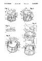
- FIG. 1is a perspective view of the closure of the present invention shown in a locked, non-dispensing, closed orientation;
- FIG. 2is a perspective view of the closure shown in an unlocked, open, dispensing orientation
- FIG. 3is a fragmentary, front elevational view of the closure in the open orientation shown in FIG. 2 as taken generally along the plane 3--3 in FIG. 2;
- FIG. 4is an enlarged, exploded, perspective view of the closure with portions of the structure cut away to illustrate interior detail;
- FIG. 5is a perspective view of the closure with the actuator removed to reveal interior detail
- FIG. 6is a greatly enlarged, cross-sectional view taken generally along the plane 6--6 in FIG. 1;
- FIG. 7is a fragmentary, cross-sectional view taken generally along the plane 7--7 FIG. 6 with the body omitted for ease of illustration;
- FIG. 8is a greatly enlarged, cross-sectional view taken generally along the plane 8--8 in FIG. 2;
- FIG. 9is a fragmentary, cross-sectional view taken generally along the plane 9--9 in FIG. 8 with the body omitted for ease of illustration;
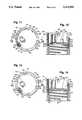
- FIG. 10is an enlarged, exploded, perspective view of another embodiment of the closure with portions of the structure cut away to reveal interior detail;
- FIG. 11is a plan view of the assembled body and locking ring shown partially in cross section
- FIG. 12is a cross-sectional view taken generally along the plane 12--12 in FIG. 11;
- FIG. 13is a view similar to FIG. 11 but showing the locking ring in a rotated orientation
- FIG. 14is a cross-sectional view taken generally along the plane 14--14 in FIG. 13.
- closure of this inventionis described in an upright position, and terms such as upper, lower, horizontal, etc., are used with reference to this position. It will be understood, however, that the closure of this invention may be manufactured, stored, transported, used, and sold in an orientation other than the position described.
- FIG. 1shows an embodiment of the dispensing closure of the present invention in the locked closed, non-dispensing position wherein the closure is represented generally by reference numeral 20.
- the closure 20is adapted to be mounted on a container (not illustrated) which may have a conventional open mouth defined by a neck (not illustrated) or other suitable structure.
- the closure 20includes a closure base or body 24 (FIG. 4) for securement to the container.
- the body 24includes a generally cylindrical, peripheral, upper wall 26 and a generally cylindrical, reduced-diameter, lower wall 27.
- a generally transverse closure wall or deck 28(FIGS. 4, 6, and 8) extends across the body 24 between the upper wall 26 and lower wall 27.
- the lower, cylindrical wall 27 of the closure body 24is adapted to engage the outer periphery of the top of the container neck (not illustrated) around the container mouth, as with threads 29 (FIGS. 6 and 8).
- Other suitable engaging meanse.g., snap-fit beads
- the closure body 24could be non-releasably attached to, or formed unitary with, the container.
- An annular sealing ring 30may be provided as shown in FIGS. 6 and 8 for engaging an interior edge of the container neck at the container mouth to effect a tight seal.
- the closure body 24includes a discharge aperture or passage 40 through the deck 28 as best illustrated in FIGS. 4, 5, 6, and 8.
- the closure body 24includes a discharge tube 42 projecting upwardly from the deck 28, and the discharge aperture 40 is defined within, and through, the tube 42.
- the discharge aperture 40 in the tube 42communicates through the deck 28 with the container interior at the lower end of the tube 42.
- the cylindrical, upper wall 26 of the closure body 24extends upwardly above, and around, the closure body deck 28.
- a rear portion of the wall 26 above the deck 28defines a fingerwell or finger recess area 44 in the form of a cutout or notch in the top edge of the wall 26.
- the closure body 24receives a generally disc-like nozzle assembly, actuator means, or actuator 60.
- the actuator 60includes a transverse top wall 62 and a peripheral flange 64 (FIGS. 1, 2, 3, 4, 5, and 6). At each of two diametrically opposed portions of the flange 64 there is a projecting, hemispherical protuberance or pivot member 66 (FIGS. 4, 6, and 8).
- the pivot members 66cooperate with the closure body upper wall 26 to mount the actuator 60 for pivoting movement within the closure body 24.
- the inner surface of the closure body wall 26defines two hemispherical recesses 68 (FIGS. 5 and 6) for each mating with one of the pivot members 66 to provide a snap-action engagement of the pivot member 66. This accommodates the pivoting movement of the actuator 60 about a pivot axis defined by the pivot members 66 and receiving recesses 68.
- the top edge of the wall 26, above each recess 68,is preferably provided with a chamfer 69 for facilitating assembly.
- the actuator pivot members 66 and body recesses 68function as mounting means so that the actuator 60 can be pivoted (by pushing downwardly on the rear portion of the actuator 60) until the forward end is exposed above the closure body wall 26 as illustrated in FIGS. 2, 3, and 8.
- the actuator 60includes a structure on the bottom surface of the top wall 62 which functions----depending upon the orientation of the actuator 60----to either permit dispensing of flowable material from the body discharge tube 42 or occlude the tube passage 40 so as to prevent flow out of the discharge tube 42.
- the actuator 60includes a forwardly extending nozzle or channel 70 which merges with, and opens into, a stepped, cylindrical sealing wall 79.
- the wall 79surrounds and seals the upper periphery of the discharge tube 42 when the actuator 60 is in the closed position as illustrated in FIG. 6.
- the wall 79forms a seal around the outer periphery of the discharge tube 42 as indicated by reference number 80 at the front of the tube 42 and as indicated by the reference numeral 84 at the rear of the tube 42.
- a sealing plug 86projects downwardly from the bottom of the actuator top wall 62.
- the sealing plug 86has a generally cylindrical or annular configuration and is adapted to enter into the opening at the top of the discharge tube 42 to sealingly occlude the discharge aperture 40 in the tube 42 when the actuator is in the closed position as illustrated in FIG. 6.
- the actuator 60can be pivoted to the open position by applying a downwardly directed force at a location on the top of the actuator 60.
- a rear portion of the actuator top wall 62is recessed within a downwardly sloping surface 90 (FIGS. 1, 2, and 4) for receiving the end of a thumb or finger.
- a locking tab 92projects downwardly from the bottom of the peripheral flange 64 at the rear of the actuator 60.
- the locking tab 92defines a downwardly facing engaging surface 94.
- An angled cam 98projects rearwardly from the outer, vertical surface of the actuator flange 64 at the rear of the actuator 60.
- the closure body cylindrical, upper wall 26defines a small vertically oriented rib 100 which is radially aligned with the cam 98 on the back of the actuator 60.
- the cam 98thus serves to stabilize the actuator 60 as it is being pivoted, and the cam 98 provides a frictional engagement to maintain the actuator in the tilted, open position.
- the actuator 60can be returned to the closed position by pushing down on the front part of the actuator.
- a novel twist ring or locking ring 120is adapted to be mounted to the closure body 24 for rotation relative to both the closure body 24 and container on which the closure body 24 is mounted.
- the closure body 24is provided with a novel configuration for receiving and retaining the locking ring 120.
- the closure body 24defines three arcuate slots 124 (two of which are visible in FIGS. 4, 5, 6, and 8).
- the three slots 124each have the same arc length and are equally spaced around the periphery of the closure body deck 28.
- a portion of each slot 124extends radially inwardly into the deck 28, and a portion of each slot extends upwardly into a portion of the peripheral, upper, cylindrical wall 26.
- the slots 124are open downwardly along side the closure deck 28 at the exterior surface of the lower, cylindrical wall 27. Adjacent each slot 124 there is a semi-cylindrical protuberance 132 projecting upwardly from the top surface of the closure body deck 28.
- lower wall 27On the exterior surface of the closure body cylindrical, lower wall 27 there are three, peripherally spaced, outwardly projecting ribs 136 for engaging the locking ring 120 as explained in detail hereinafter.
- the locking ring 120has a generally cylindrical configuration. On the inside of the ring 120 there are three rib structures 150, and each rib structure 150 has two downwardly extending, and inwardly projecting, legs or ribs 152 (FIGS. 4, 7, and 9). At the top of the ring 120, the two ribs 152 which form the legs of each rib structure 150 merge and define an inverted, U-shaped or hook-shaped clip 160. Each clip 160 has an inwardly and downwardly projecting distal end for engaging the body deck 28. The bottom of the distal end of each clip 160 defines a semi-cylindrical recess 162 for receiving one of the semi-cylindrical protuberances 132.
- an abutment tab 168projects upwardly from one of the three clips 160.
- the top of the abutment tab 168defines an upwardly facing abutment surface 170 for being engaged by the downwardly facing engagement surface 94 of the actuator locking tab 92.
- the locking ring 120can be assembled with the closure body 24 before or after the actuator 60 has been mounted in the closure body 24. To this end, the locking ring 120 is aligned with the closure body cylindrical, lower wall 27, and then relative axial displacement is effected between the closure body 24 and the locking ring 120 so as to position each locking ring clip 160 in a closure body slot 124. During this assembly process, the distal ends of the clips 160 are temporarily distorted and compressed in the radially outward direction so as to accommodate movement into and through the slots 124. When the bottom of the downturned distal end of each clip 160 clears the top surface of the closure body deck 28, the clip 160 springs radially inwardly to its original, undeformed condition. The distal end of each clip 160 thus extends inwardly over, and engages, the closure body deck 28. This serves to retain the locking ring 120 on the closure body 24 while permitting the relative rotation between the ring 120 and the body 24.
- Selected rotational positions of the locking ring 120can be indicated or established by means of a low force, snap-fit engagement between each clip 160 and one of the semi-cylindrical protuberances 132 which project upwardly from the closure body deck 28.
- two of the locking ring clips 160are each positioned over, and in engagement with, a protrusion 132.
- each clip 160is resiliently deformable upwardly away from the deck 28, and each clip recess 162 matingly receives a deck protrusion 132. This provides resistance to further rotation of the ring 120 in either direction, and this provides a tactile sensation indicating that the ring 120 is at a desired rotational orientation.
- the ring 120In one rotated position, the ring 120 is oriented so that the upwardly projecting abutment member 168 is positioned beneath the actuator engaging tab 92 (FIGS. 6 and 7). In this position, the actuator tab engaging surface 94 engages the locking ring tab abutment surface 170 to prevent the actuator 60 from being tilted to the open position.
- the locking ring 120is releasably held in this position by the engagement between the locking ring clips 160 and the closure body deck protrusions 132.
- the locking ring 120can be rotated from the locked position (FIGS. 6 and 7) to an unlocked position (FIGS. 8 and 9) by rotating the ring 120 in the direction of the arrow 184 as viewed in FIG. 9 (clockwise when looking down on the closure as in FIG. 2). As soon as the ring 120 moves the abutment tab 168 an amount sufficient to clear the actuator tab 92, the actuator 60 can be tilted to the open position (FIG. 8).
- each of the ring clips 160is adapted to engage one of the closure body deck protuberances 132 when the abutment tab 168 and engaging tab 92 are in a non-engaging, non-aligned relationship (FIG. 9).
- the engagement of each clip 162 with a closure body deck protuberance 132again provides a resistance to further relative movement between the ring 120 and closure 24. This serves to provide a tactile indication that the components have been moved to the end of the movement range which permits tilting of the actuator 60 to the open position.
- the closure body ribs 136 and ring ribs 152facilitate the screwing of the closure onto the container with or without an automatic capping machine.
- the locking ring 120can be gripped, as with the head of an automatic capping machine, to align the closure, and hence the closure body lower wall 27, with the container neck.
- the capping machinerotates the locking ring 120 (in a clockwise direction when viewing downwardly on the top of the closure).
- the locking ring ribs 152move with the ring relative to the closure body 24 until the leading ribs 152 engage the ribs 136 on the closure body lower wall 27. This establishes a driving engagement between the locking ring 120 and closure body 24 which threads the closure tightly onto the container with the abutment member 168 maintained under the actuator tab 92 so as to prevent the actuator 60 from being tilted open.
- the cylindrical, upper wall 26 of the closure body 24is provided with two, molded indentations: a first indentation 191 bearing the molded letter "C” and a second indentation 192 bearing the molded letter “O.”
- the locking ring 120has a single indentation with a molded, triangular shaped pointer 194 (FIGS. 1 and 2).
- the locations of these molded featurescorrespond to the "open" (unlocked) and "closed” (locked) positions of the locking ring 120. That is, when the locking ring 120 is positioned as illustrated in FIG. 1 so that the locking ring abutment member 168 (FIG. 7) prevents the actuator 60 from being tilted open, the locking ring pointer 194 is aligned with the closure body indentation 191 bearing the letter “C.” On the other hand, when the locking ring pointer 194 is aligned with the closure body letter “O” in the indentation 192 (FIG. 2). This indicates to the user that the actuator 60 can be pressed to tilt it to the open, dispensing position.
- FIGS. 10-14A second embodiment of the closure of the present invention is illustrated in FIGS. 10-14 wherein the closure is designated generally by the reference numeral 220 (FIG. 10).
- the closure 220is adapted to be mounted on a container (not illustrated) which may have a conventional open mouth defined by a neck (not illustrated) or other suitable structure.
- the closure 220includes a closure base or body 224 (FIG. 10) for securement to the container.
- the body 224includes a generally cylindrical, peripheral, upper wall 226 and a generally cylindrical, reduced-diameter, lower wall 227.
- a generally transverse closure wall or deck 228extends across the body 224 between the upper wall 226 and lower wall 227.
- the lower, cylindrical wall 227 of the closure body 224is adapted to engage the outer periphery of the top of the container neck (not illustrated) around the container mouth, as with threads 229 (FIGS. 12 and 14).
- Other suitable engaging meanse.g., snap-fit beads
- the closure body 224could be non-releasably attached to, or formed unitary with, the container.
- An annular sealing ring 230may be provided as shown in FIGS. 12 and 14 for engaging an interior edge of the container neck at the container mouth to effect a tight seal.
- the closure body 224includes a discharge aperture or passage 240 through the deck 228.
- the closure body 224includes a discharge tube 242 projecting upwardly from the deck 228, and the discharge aperture 240 is defined within, and through, the tube 242.
- the discharge aperture 240 in the tube 242communicates through the deck 228 with the container interior at the lower end of the tube 242.
- the cylindrical, upper wall 226 of the closure body 224extends upwardly above, and around, the closure body deck 228.
- a rear portion of the wall 226 above the deck 228defines a fingerwell or finger recess area 244 in the form of a cutout or notch in the top edge of the wall 226.
- the closure body 224receives a generally disc-like nozzle assembly, actuator means, or actuator 260.
- the actuator 260includes a transverse top wall 262 and a peripheral flange 264. At each of two diametrically opposed portions of the flange 264 there is a projecting, hemispherical protuberance or pivot member 266.
- the pivot members 266cooperate with the closure body upper wall 226 to mount the actuator 260 for pivoting movement within the closure body 224.
- the inner surface of the closure body wall 226defines two hemispherical recesses 268 for each mating with one of the pivot members 266 to provide a snap-action engagement of the pivot member 266. This accommodates the pivoting movement of the actuator 260 about a pivot axis defined by the pivot members 266 and receiving recesses 268.
- the top edge of the wall 226, above each recess 268,is preferably provided with a chamfer 269 for facilitating assembly.
- the actuator pivot members 266 and body recesses 268function as mounting means so that the actuator 260 can be pivoted (by-pushing downwardly on the rear portion of the actuator 260) until the forward end is exposed above the closure body wall 226 (in a manner similar to that shown for the first embodiment actuator 60 illustrated in FIGS. 2, 3, and 9).
- the actuator 260has an internal structure identical to that of the first embodiment actuator 60 described above with reference to FIGS. 1-9.
- the internal structurefunctions, depending upon the orientation of the actuator 260, to either permit dispensing of flowable material from the body discharge tube 242 or occlude the tube passage 240 so as to prevent flow out of the discharge tube 242.
- a locking tab 292projects downwardly from the bottom of the peripheral flange 264 at the rear of the actuator 260.
- the locking tab 292defines a downwardly facing engaging surface 294.
- a novel twist ring or locking ring 320is adapted to be mounted to the closure body 224 for rotation relative to both the closure body 224 and container on which the closure body 224 is mounted.
- the closure body 224is provided with a novel configuration for receiving and retaining the locking ring 320.
- the closure body 224defines one arcuate slot 324 at the junction of the deck 228 and cylindrical, upper wall 226. A portion of the slot 324 extends radially inwardly into the deck 228, and a portion of the slot 324 extends upwardly into a portion of the peripheral, upper, cylindrical wall 226. Because the closure body lower, cylindrical wall 227 has a smaller diameter than the upper wall 226, the slot 324 is open downwardly along side the closure deck 228 at the exterior surface of the lower, cylindrical wall 227.
- each body rib 235, 236, and 237terminates somewhat below the body transverse deck 228.
- the lower wall 227flares outwardly to form a flange defined by a frustoconical lower surface 340 and an upwardly facing, annular bearing surface 342.
- the bearing surface 342is spaced somewhat below the bottom surface of the body transverse deck 228.
- the locking ring 320has a generally cylindrical configuration. On the inside of the ring 320, as visible in FIG. 10, there are six ribs 351, 352, 353, 354, 355, and 356. The ribs 351-356 do not extend all the way to the top of the locking ring 320. At the top of the ring 320 there is an inwardly extending flange defined by a frustoconical surface 361 and a downwardly facing engaging surface 363. The flange surfaces 361 and 363 extend radially inwardly, but the flange is slotted, as at 363A, over the upper ends of each of the ribs 351-356 which are spaced below the surface 363. The slots 363A accommodate the tool configuration of the mold assembly used for molding the ring 320.
- An abutment member 368projects upwardly from the locking ring frustoconical surface 361.
- the top of the abutment member 368defines an upwardly facing abutment surface 370 for being engaged by the downwardly facing engagement surface 294 of the actuator locking tab 292 as explained in detail hereinafter.
- the locking ring 320can be assembled with the closure body 224 before or after the actuator 260 has been mounted in the closure body 224. To this end, the locking ring 320 is aligned with the closure body cylindrical, lower wall 227, and then relative axial displacement is effected between the closure body 224 and the locking ring 320 so as to force the locking ring flange frustoconical surface 361 past the body flange frustoconical surface 340 by temporarily distorting or deforming one or both of the components. After sufficient axial displacement has been effected, the components are returned to their original shapes, owing to the inherent resiliency of the component materials, so that the locking ring flange engaging surface 363 overlies, and is supported by, the body bearing surface 342. This serves to retain the locking ring 320 on the closure body 224 while permitting the relative rotation between the ring 320 and body 224.
- the two componentsare aligned, by effecting relative rotation if necessary, so as to position the locking ring abutment tab 368 within the body slot 324.
- the abutment member 368enters the body slot 324 and becomes positioned adjacent the cylindrical, upper wall 226 of the closure body 224 as illustrated in FIGS. 11-14.
- the abutment member 368is adapted to be positioned beneath the actuator tab 292 to prevent or block tilting of the actuator tab 260 to the open, dispensing position. This blocking action is effected by rotating the locking ring 320 in the direction of the arrow 376 in FIG. 13. This positions the abutment member 368 under the actuator tab 294. The engaging surface 294 of the actuator engaging tab 292 thus confronts the upwardly facing abutment surface 370 of the abutment member 368, and the actuator 260 cannot be tilted to the open position.
- the locking ring 320can be rotated in the other direction, in the direction of the arrow 378 as illustrated in FIG. 11, to permit the actuator 260 to be tilted to the open position.
- the locking ring 320can be rotated in the direction of the arrow 378 until the locking ring ribs 352, 354, and 356 engage the body ribs 235, 236, and 237, respectively. This prevents further rotation of the locking ring 320 at a point where the abutment member 368 has been moved sufficiently far from the actuator tab 292 to permit the actuator 260 to be tilted open.
- such rib engagementserves to provide a tactile indication that the components have been moved to the end of the movement range which either permits or prevents the tilting of the actuator 260 to the open position.
- the cylindrical outer wall 226 of the closure body 224may be provided with two, molded indentations such as the indentations having the molded letters "C" and "O" as employed in the first embodiment illustrated in FIGS. 1 and 2 discussed above.
- the locking ring 320may be provided with a single indentation containing an appropriate indicium for being selectively aligned with one of the two indentations in the closure body so as to provide a visual indication of the locked condition or unlocked condition.
- the closure body 224is provided with threads 229 for threadingly engaging mating threads on a container neck (not illustrated)
- the closure body ribs and ring ribsfacilitate the screwing of the closure onto the container with or without an automatic capping machine.
- the locking ring 320can be gripped, as with the head of an automatic capping machine, to align the closure, and hence the closure body lower wall 227, with the container neck.
- the capping machinerotates the locking ring 320 (in a clockwise direction when viewing downwardly on the top of the closure).
- the locking ring ribsmove with the ring 320 relative to the closure body 224 until the leading ring ribs 351, 353, and 355 engage the body ribs 237, 235, and 236, respectively. This establishes a driving engagement between the locking ring 320 and closure body 224 which threads the closure tightly onto the container with the closure initially in the locked closed orientation.
- the closure of the present inventioncan be readily molded from thermoplastic materials and easily assembled to provide a stream-lined product.
- the closureprovides a desirable toggle-action dispensing operation and at the same time includes a lock for preventing, or reducing the likelihood of, an inadvertent, premature opening or actuation of the closure to the dispensing position.
Landscapes
- Engineering & Computer Science (AREA)
- Mechanical Engineering (AREA)
- Closures For Containers (AREA)
- Sealing Of Jars (AREA)
Abstract
Description
Claims (12)
Priority Applications (4)
| Application Number | Priority Date | Filing Date | Title |
|---|---|---|---|
| US07/951,871US5314093A (en) | 1992-09-25 | 1992-09-25 | Toggle-action dispensing closure with rotatable locking ring |
| EP92403346AEP0589114B1 (en) | 1992-09-25 | 1992-12-09 | Toggle-action dispensing closure with rotatable locking ring |
| ES92403346TES2104876T3 (en) | 1992-09-25 | 1992-12-09 | A CLOSURE BY A SUPPLY LEVER FOR A CONTAINER. |
| DE69220367TDE69220367T2 (en) | 1992-09-25 | 1992-12-09 | Toggle-operated dispenser closure with rotating locking ring |
Applications Claiming Priority (1)
| Application Number | Priority Date | Filing Date | Title |
|---|---|---|---|
| US07/951,871US5314093A (en) | 1992-09-25 | 1992-09-25 | Toggle-action dispensing closure with rotatable locking ring |
Publications (1)
| Publication Number | Publication Date |
|---|---|
| US5314093Atrue US5314093A (en) | 1994-05-24 |
Family
ID=25492255
Family Applications (1)
| Application Number | Title | Priority Date | Filing Date |
|---|---|---|---|
| US07/951,871Expired - Fee RelatedUS5314093A (en) | 1992-09-25 | 1992-09-25 | Toggle-action dispensing closure with rotatable locking ring |
Country Status (4)
| Country | Link |
|---|---|
| US (1) | US5314093A (en) |
| EP (1) | EP0589114B1 (en) |
| DE (1) | DE69220367T2 (en) |
| ES (1) | ES2104876T3 (en) |
Cited By (61)
| Publication number | Priority date | Publication date | Assignee | Title |
|---|---|---|---|---|
| US5379926A (en)* | 1993-03-26 | 1995-01-10 | Aptargroup, Inc. | Dispensing closure with a twist sleeve and two internal passages |
| US5547111A (en)* | 1993-06-22 | 1996-08-20 | Geiger; Reinold | Device to close a side dispensing orifice by axial sliding with push button element |
| US5622284A (en)* | 1996-04-08 | 1997-04-22 | Sawicki; Craig | Child-resistant, toggle-action closure |
| USD385791S (en)* | 1996-07-25 | 1997-11-04 | Weatherchem Corporation | Single flap push in closure with over catch |
| US5918777A (en) | 1996-02-21 | 1999-07-06 | Owens-Brockway Plastic Products Inc. | Dispensing package for viscous liquid product |
| US6029866A (en)* | 1998-09-29 | 2000-02-29 | Aptargroup, Inc. | Multiple injection, toggle-action dispensing structure |
| US6170683B1 (en) | 1999-11-16 | 2001-01-09 | Rexam Medical Packaging Inc. | Two stage dispensing cap for pressurized containers |
| US6241128B1 (en) | 1998-12-22 | 2001-06-05 | Owens-Brockway Plastic Products Inc. | Dispenser package for fluent products and method of manufacture |
| US6283333B1 (en) | 2001-01-17 | 2001-09-04 | Seaquist Closures Foreign, Inc. | Toggle-action dispensing closure with an actuation-prevention abutment and a recessed striker rib |
| US6311878B1 (en) | 2000-01-07 | 2001-11-06 | Owens-Brockway Plastics Products Inc. | Dispensing package for fluent products |
| USD451810S1 (en) | 2000-08-03 | 2001-12-11 | Jay Weinstock | Waterproof floatable container |
| US6343725B1 (en)* | 2000-12-19 | 2002-02-05 | Owens-Illinois Closure Inc. | Disk-type toggle-action dispensing closure, package and method of assembly |
| US6394323B2 (en) | 1999-08-24 | 2002-05-28 | Owens-Brockway Plastic Products Inc. | Dispenser package for fluent products and method of manufacture |
| US6401990B1 (en) | 2000-06-19 | 2002-06-11 | Seaquist Closures Foreign, Inc. | Finger-operable pump actuator with finger pad |
| US6481589B2 (en) | 2001-02-22 | 2002-11-19 | Seaquist Closures Foreign, Inc. | Non-dispensing closure |
| US6564978B1 (en)* | 2001-02-12 | 2003-05-20 | Owens-Brockway Plastic Products Inc. | Disk-top fluid dispensing package |
| US20030201283A1 (en)* | 2002-04-26 | 2003-10-30 | Rexam Medical Packaging Inc. | Child resistant dispenser |
| US6691394B1 (en) | 2001-02-12 | 2004-02-17 | Owens-Brockway Plastic Products Inc. | Disk-top fluid dispensing package |
| US20040112927A1 (en)* | 2002-12-12 | 2004-06-17 | Brett Kaufman | Lockable disc top dispensing closure |
| US20040134286A1 (en)* | 2003-01-09 | 2004-07-15 | Gammon James H. | Nozzle test fixture |
| US20040149787A1 (en)* | 2003-02-05 | 2004-08-05 | Christopher Englert | Dispensing package with lockable closure |
| US20040159684A1 (en)* | 2003-02-18 | 2004-08-19 | Seaquist Closures Foreign, Inc. | Toggle-action dispensing closure with an actuation-prevention system incorporating permanent deformation |
| USD509426S1 (en) | 1997-10-28 | 2005-09-13 | Gateway Plastics, Inc. | Integrally-formed closure for a container |
| USD513452S1 (en) | 2002-09-27 | 2006-01-10 | Gateway Plastics, Inc. | Closure for a container |
| USD532298S1 (en) | 2004-11-20 | 2006-11-21 | Gateway Plastics, Inc. | Closure for a container |
| USD532691S1 (en) | 2004-11-20 | 2006-11-28 | Gateway Plastics, Inc. | Closure for a container |
| USD533452S1 (en) | 2004-11-20 | 2006-12-12 | Gateway Plastics, Inc. | Closure for a container |
| USD537342S1 (en) | 2005-10-25 | 2007-02-27 | Seaquist Closures Foreign, Inc. | Closure |
| USD538161S1 (en) | 2005-10-25 | 2007-03-13 | Seaquist Closures Foreign, Inc. | Closure |
| USD576038S1 (en) | 2007-12-21 | 2008-09-02 | Seaquist Closures L.L.C. | Dispensing closure with thumb or finger push down pivoting actuator |
| USD576488S1 (en) | 2006-10-17 | 2008-09-09 | Seaquist Closures Foreign, Inc. | Closure |
| USD576489S1 (en) | 2007-05-07 | 2008-09-09 | Seaquist Closures, L.L.C. | Dispensing closure with thumb or finger push down actuator |
| USD576490S1 (en) | 2007-12-21 | 2008-09-09 | Seaquist Closures L.L.C. | Dispensing closure with thumb or finger push down pivoting actuator |
| USD608200S1 (en) | 2009-02-05 | 2010-01-19 | Seaquist Closures L.L.C. | Dispensing closure body for use with a thumb or finger push down pivoting actuator |
| USD636668S1 (en) | 2008-03-24 | 2011-04-26 | Mary Kay Inc. | Dip tubes |
| US20120104052A1 (en)* | 2009-09-22 | 2012-05-03 | Andrew Offord | Vessel closure-sealable pouring spout assembly |
| US20130026188A1 (en)* | 2010-01-13 | 2013-01-31 | Aptar Freyung Gmbh | Dispensing closure for an opening of a container |
| US8376192B2 (en) | 2008-03-24 | 2013-02-19 | Mary Kay Inc. | Apparatus for dispensing fluids using a press-fit diptube |
| USD682101S1 (en) | 2012-09-04 | 2013-05-14 | Aptargroup, Inc. | Closure |
| US20140305899A1 (en)* | 2013-04-12 | 2014-10-16 | Patrick Kidd | Bottle closure and method of using the same |
| US9555939B2 (en)* | 2015-03-04 | 2017-01-31 | Marwan Chehadeh | Bottle for upright and inverted use |
| US9789502B2 (en) | 2008-06-05 | 2017-10-17 | Mary Kay Inc. | Apparatus for dispensing fluids using a removable bottle |
| WO2018128627A1 (en) | 2017-01-09 | 2018-07-12 | Aptargroup, Inc. | Dispensing closure |
| US10167120B1 (en) | 2018-02-20 | 2019-01-01 | Navajo Manufacturing Company, Inc. | Travel bottle with twisting locking lid |
| US20190092539A1 (en)* | 2017-09-28 | 2019-03-28 | Aptargroup, Inc. | Closure for a container |
| WO2019129567A1 (en) | 2017-12-28 | 2019-07-04 | Unilever Plc | Closure |
| USD854415S1 (en) | 2018-02-20 | 2019-07-23 | Navajo Manufacturing Company, Inc. | Travel bottle cap with twisting locking lid |
| USD867140S1 (en) | 2018-09-06 | 2019-11-19 | Navajo Manufacturing Company, Inc. | Travel bottle cap |
| USD867138S1 (en) | 2018-09-06 | 2019-11-19 | Navajo Manufacturing Company, Inc. | Travel bottle cap with slide lock |
| USD867139S1 (en) | 2018-09-06 | 2019-11-19 | Navajo Manufacturing Company, Inc. | Travel bottle cap with rotatable lock |
| US10604309B2 (en) | 2018-06-19 | 2020-03-31 | Navajo Manufacturing Company, Inc. | Travel bottle with slide lock |
| US10669082B1 (en) | 2019-06-17 | 2020-06-02 | Packaging Concepts Associates Holding, Inc. | Child-resistant disk-top closure and locking system for a container |
| US10745179B2 (en) | 2018-02-20 | 2020-08-18 | Navajo Manufacturing Company, Inc. | Travel bottle with slide or rotatable lock |
| US10752412B1 (en) | 2019-11-06 | 2020-08-25 | Berlin Packaging, Llc | Child resistant container with pump actuator |
| USD902716S1 (en) | 2019-05-16 | 2020-11-24 | Navajo Manufacturing Company, Inc. | Travel bottle cap having a twisting locking ring body |
| US10988291B2 (en) | 2019-05-16 | 2021-04-27 | Navajo Manufacturing Company, Inc. | Travel bottle having a twisting locking ring body |
| USD920805S1 (en) | 2019-05-30 | 2021-06-01 | Berlin Packaging, Llc | Container with pump actuator |
| US11040809B1 (en) | 2020-10-09 | 2021-06-22 | Packaging Concepts Associates Holding, Inc. | Push button tilt top closure and locking system for a container |
| WO2021154208A1 (en)* | 2020-01-28 | 2021-08-05 | Aptargroup, Inc. | Dispensing closure |
| US11987425B2 (en) | 2018-09-17 | 2024-05-21 | Conopco, Inc. | Flip top closure and container |
| WO2024237572A1 (en)* | 2023-05-12 | 2024-11-21 | (주)콜러디 | Locking device for container, and container assembly having same |
Families Citing this family (10)
| Publication number | Priority date | Publication date | Assignee | Title |
|---|---|---|---|---|
| GB2295385B (en)* | 1994-11-22 | 1999-05-19 | Anthony Charles Lammond Wass | Two-piece dispensing closure cap |
| WO1999036328A1 (en)* | 1998-01-20 | 1999-07-22 | The Procter & Gamble Company | Dispensing closure with integral locking switch and tamper evidency structure |
| DE19807921A1 (en) | 1998-02-25 | 1999-08-26 | Pfeiffer Erich Gmbh & Co Kg | Discharge control for a media donor |
| DE10002088B4 (en)* | 2000-01-19 | 2005-09-29 | Seaquist Perfect Dispensing Gmbh | Lockable actuator for a dispenser of a liquid container |
| US20040238539A1 (en)* | 2003-06-02 | 2004-12-02 | Valentin Hierzer | Hinged dispensing closure with child-resistant interlock |
| DE102004017120A1 (en)* | 2004-04-07 | 2005-10-27 | Wella Ag | Secured disk-top fastener for container, has rotary ring connected with fastener by rotary connection, where ring has bar that is provided directly above disk to prevent swiveling of disk in position rotated up to ninety degrees |
| GB201516188D0 (en)* | 2015-09-14 | 2015-10-28 | Obrist Closures Switzerland | A dispensing closure |
| CN105819086B (en)* | 2016-05-16 | 2018-08-24 | 中山市华宝勒生活用品实业有限公司 | It is a kind of to press open container |
| EP4021820B1 (en)* | 2019-08-30 | 2024-07-31 | Johnson & Johnson Consumer Inc. | Dispensing closure |
| CN112298784B (en)* | 2020-10-20 | 2021-09-14 | 珠海格力电器股份有限公司 | Storage structure capable of loading content |
Citations (20)
| Publication number | Priority date | Publication date | Assignee | Title |
|---|---|---|---|---|
| US3007614A (en)* | 1958-04-28 | 1961-11-07 | Fred A Morrow | Dispenser closure |
| DE2120079A1 (en)* | 1971-04-24 | 1972-11-16 | Aerosol-Technik Lindal Gmbh, 2060 Bad Oldesloe | Spray cap for aerosol cans |
| US3776428A (en)* | 1972-04-28 | 1973-12-04 | Polytop Corp | Safety closure useable on threaded container neck |
| US3782577A (en)* | 1972-03-27 | 1974-01-01 | Sandra Levey Miller | Combination lockable closure spout |
| US4047643A (en)* | 1972-03-20 | 1977-09-13 | Polytop Corporation | Safety dispensing closure with movable retainer |
| US4065036A (en)* | 1976-12-06 | 1977-12-27 | Vca Corporation | Actuator cap having a button rotatably between dispensing and non-dispensing positions |
| US4412634A (en)* | 1981-11-10 | 1983-11-01 | Bennett Robert A | Cap and neck unit for fluid dispenser |
| FR2541749A1 (en)* | 1983-02-25 | 1984-08-31 | Valois Sa | SAFETY OPERATING DEVICE FOR AEROSOL VALVE |
| US4487342A (en)* | 1982-05-11 | 1984-12-11 | Shy Min C | Pushbutton type bottle cap |
| US4542837A (en)* | 1983-03-12 | 1985-09-24 | Metal Box P.L.C. | Aerosol actuator |
| US4763801A (en)* | 1987-10-08 | 1988-08-16 | Owens-Illinois Closure Inc. | Child-resistant, tamper evident dispensing closure |
| US4773567A (en)* | 1986-04-21 | 1988-09-27 | Stoody William R | Child resistant latching actuator for aerosol/pump valve |
| US4776501A (en)* | 1987-08-31 | 1988-10-11 | Seaquist Closures | Self-closing, press-to-open, dispensing closure |
| US4838460A (en)* | 1987-10-09 | 1989-06-13 | Calmar Corporation | Product dispenser having actuator locking collar and shroud |
| US4941580A (en)* | 1989-05-26 | 1990-07-17 | Sunbeam Plastics Corporation | Dispensing closure |
| US4962869A (en)* | 1989-04-11 | 1990-10-16 | Sequist Closures | Toggle-acting dispensing closure with impact resistance |
| US4972974A (en)* | 1989-09-18 | 1990-11-27 | Product Resources International, Inc. | Childproof dispenser |
| US4982882A (en)* | 1987-12-24 | 1991-01-08 | L'oreal | Cap for dispensing a fluid or viscous product, and container equipped with such a cap |
| US5004127A (en)* | 1988-05-11 | 1991-04-02 | Simone Morel | Cap with a rotating casing for flasks, tubes and similar containers |
| US5065912A (en)* | 1989-07-06 | 1991-11-19 | Bielsteiner Verschlusstechnik Gmbh | Biased swivel closure |
Family Cites Families (1)
| Publication number | Priority date | Publication date | Assignee | Title |
|---|---|---|---|---|
| US3623622A (en)* | 1970-07-13 | 1971-11-30 | Westhem Corp Ltd | Safety locking closure |
- 1992
- 1992-09-25USUS07/951,871patent/US5314093A/ennot_activeExpired - Fee Related
- 1992-12-09DEDE69220367Tpatent/DE69220367T2/ennot_activeExpired - Fee Related
- 1992-12-09EPEP92403346Apatent/EP0589114B1/ennot_activeExpired - Lifetime
- 1992-12-09ESES92403346Tpatent/ES2104876T3/ennot_activeExpired - Lifetime
Patent Citations (20)
| Publication number | Priority date | Publication date | Assignee | Title |
|---|---|---|---|---|
| US3007614A (en)* | 1958-04-28 | 1961-11-07 | Fred A Morrow | Dispenser closure |
| DE2120079A1 (en)* | 1971-04-24 | 1972-11-16 | Aerosol-Technik Lindal Gmbh, 2060 Bad Oldesloe | Spray cap for aerosol cans |
| US4047643A (en)* | 1972-03-20 | 1977-09-13 | Polytop Corporation | Safety dispensing closure with movable retainer |
| US3782577A (en)* | 1972-03-27 | 1974-01-01 | Sandra Levey Miller | Combination lockable closure spout |
| US3776428A (en)* | 1972-04-28 | 1973-12-04 | Polytop Corp | Safety closure useable on threaded container neck |
| US4065036A (en)* | 1976-12-06 | 1977-12-27 | Vca Corporation | Actuator cap having a button rotatably between dispensing and non-dispensing positions |
| US4412634A (en)* | 1981-11-10 | 1983-11-01 | Bennett Robert A | Cap and neck unit for fluid dispenser |
| US4487342A (en)* | 1982-05-11 | 1984-12-11 | Shy Min C | Pushbutton type bottle cap |
| FR2541749A1 (en)* | 1983-02-25 | 1984-08-31 | Valois Sa | SAFETY OPERATING DEVICE FOR AEROSOL VALVE |
| US4542837A (en)* | 1983-03-12 | 1985-09-24 | Metal Box P.L.C. | Aerosol actuator |
| US4773567A (en)* | 1986-04-21 | 1988-09-27 | Stoody William R | Child resistant latching actuator for aerosol/pump valve |
| US4776501A (en)* | 1987-08-31 | 1988-10-11 | Seaquist Closures | Self-closing, press-to-open, dispensing closure |
| US4763801A (en)* | 1987-10-08 | 1988-08-16 | Owens-Illinois Closure Inc. | Child-resistant, tamper evident dispensing closure |
| US4838460A (en)* | 1987-10-09 | 1989-06-13 | Calmar Corporation | Product dispenser having actuator locking collar and shroud |
| US4982882A (en)* | 1987-12-24 | 1991-01-08 | L'oreal | Cap for dispensing a fluid or viscous product, and container equipped with such a cap |
| US5004127A (en)* | 1988-05-11 | 1991-04-02 | Simone Morel | Cap with a rotating casing for flasks, tubes and similar containers |
| US4962869A (en)* | 1989-04-11 | 1990-10-16 | Sequist Closures | Toggle-acting dispensing closure with impact resistance |
| US4941580A (en)* | 1989-05-26 | 1990-07-17 | Sunbeam Plastics Corporation | Dispensing closure |
| US5065912A (en)* | 1989-07-06 | 1991-11-19 | Bielsteiner Verschlusstechnik Gmbh | Biased swivel closure |
| US4972974A (en)* | 1989-09-18 | 1990-11-27 | Product Resources International, Inc. | Childproof dispenser |
Cited By (92)
| Publication number | Priority date | Publication date | Assignee | Title |
|---|---|---|---|---|
| US5379926A (en)* | 1993-03-26 | 1995-01-10 | Aptargroup, Inc. | Dispensing closure with a twist sleeve and two internal passages |
| US5547111A (en)* | 1993-06-22 | 1996-08-20 | Geiger; Reinold | Device to close a side dispensing orifice by axial sliding with push button element |
| US6041975A (en) | 1996-02-21 | 2000-03-28 | Owens-Brockway Plastic Products Inc. | Dispensing package for viscous liquid product |
| US5918777A (en) | 1996-02-21 | 1999-07-06 | Owens-Brockway Plastic Products Inc. | Dispensing package for viscous liquid product |
| US5622284A (en)* | 1996-04-08 | 1997-04-22 | Sawicki; Craig | Child-resistant, toggle-action closure |
| USD385791S (en)* | 1996-07-25 | 1997-11-04 | Weatherchem Corporation | Single flap push in closure with over catch |
| USD509426S1 (en) | 1997-10-28 | 2005-09-13 | Gateway Plastics, Inc. | Integrally-formed closure for a container |
| USD530610S1 (en) | 1997-10-28 | 2006-10-24 | Gateway Plastic, Inc. | Integrally-formed closure for a container |
| US6029866A (en)* | 1998-09-29 | 2000-02-29 | Aptargroup, Inc. | Multiple injection, toggle-action dispensing structure |
| US6241128B1 (en) | 1998-12-22 | 2001-06-05 | Owens-Brockway Plastic Products Inc. | Dispenser package for fluent products and method of manufacture |
| US6757957B2 (en) | 1998-12-22 | 2004-07-06 | Owens-Brockway Plastic Products Inc. | Dispenser package for fluent products and method of manufacture |
| US6615473B2 (en) | 1998-12-22 | 2003-09-09 | Owens-Brockway Plastic Products Inc. | Method of making a container and closure |
| US6622895B2 (en) | 1999-08-24 | 2003-09-23 | Owens-Brockway Plastic Products Inc. | Dispenser package for fluent products and method of manufacture |
| US6394323B2 (en) | 1999-08-24 | 2002-05-28 | Owens-Brockway Plastic Products Inc. | Dispenser package for fluent products and method of manufacture |
| US6170683B1 (en) | 1999-11-16 | 2001-01-09 | Rexam Medical Packaging Inc. | Two stage dispensing cap for pressurized containers |
| US6311878B1 (en) | 2000-01-07 | 2001-11-06 | Owens-Brockway Plastics Products Inc. | Dispensing package for fluent products |
| US6357625B2 (en) | 2000-01-07 | 2002-03-19 | Owens-Brockway Plastics Products Inc. | Dispensing packages for fluent products |
| US6401990B1 (en) | 2000-06-19 | 2002-06-11 | Seaquist Closures Foreign, Inc. | Finger-operable pump actuator with finger pad |
| USD451810S1 (en) | 2000-08-03 | 2001-12-11 | Jay Weinstock | Waterproof floatable container |
| US6431416B1 (en) | 2000-12-19 | 2002-08-13 | Owens-Illinois Closure Inc. | Disk-type toggle-action dispensing closure, package and method of assembly |
| US6343725B1 (en)* | 2000-12-19 | 2002-02-05 | Owens-Illinois Closure Inc. | Disk-type toggle-action dispensing closure, package and method of assembly |
| US6283333B1 (en) | 2001-01-17 | 2001-09-04 | Seaquist Closures Foreign, Inc. | Toggle-action dispensing closure with an actuation-prevention abutment and a recessed striker rib |
| US6691394B1 (en) | 2001-02-12 | 2004-02-17 | Owens-Brockway Plastic Products Inc. | Disk-top fluid dispensing package |
| US6564978B1 (en)* | 2001-02-12 | 2003-05-20 | Owens-Brockway Plastic Products Inc. | Disk-top fluid dispensing package |
| US6481589B2 (en) | 2001-02-22 | 2002-11-19 | Seaquist Closures Foreign, Inc. | Non-dispensing closure |
| US20030201283A1 (en)* | 2002-04-26 | 2003-10-30 | Rexam Medical Packaging Inc. | Child resistant dispenser |
| US6866164B2 (en)* | 2002-04-26 | 2005-03-15 | Rexam Medical Packaging Inc. | Child resistant dispenser |
| USD513452S1 (en) | 2002-09-27 | 2006-01-10 | Gateway Plastics, Inc. | Closure for a container |
| US6896160B2 (en) | 2002-12-12 | 2005-05-24 | Poly-Seal Corporation | Lockable disc top dispensing closure |
| WO2004054921A1 (en)* | 2002-12-12 | 2004-07-01 | Berry Plastics Corporation | Lockable disc top dispensing closure |
| US20040112927A1 (en)* | 2002-12-12 | 2004-06-17 | Brett Kaufman | Lockable disc top dispensing closure |
| US20040134286A1 (en)* | 2003-01-09 | 2004-07-15 | Gammon James H. | Nozzle test fixture |
| US6769309B1 (en)* | 2003-01-09 | 2004-08-03 | Gammon Technical Products, Inc. | Nozzle test fixture |
| US20040149787A1 (en)* | 2003-02-05 | 2004-08-05 | Christopher Englert | Dispensing package with lockable closure |
| WO2004071882A3 (en)* | 2003-02-05 | 2005-03-03 | Poly Seal Corp | Dispensing package with lockable closure |
| US6971547B2 (en)* | 2003-02-05 | 2005-12-06 | Berry Plastics Corporation | Dispensing package with lockable closure |
| US6832700B2 (en) | 2003-02-18 | 2004-12-21 | Seaquist Closures Foreign, Inc. | Toggle-action dispensing closure with an actuation-prevention system incorporating permanent deformation |
| US20040159684A1 (en)* | 2003-02-18 | 2004-08-19 | Seaquist Closures Foreign, Inc. | Toggle-action dispensing closure with an actuation-prevention system incorporating permanent deformation |
| USD532298S1 (en) | 2004-11-20 | 2006-11-21 | Gateway Plastics, Inc. | Closure for a container |
| USD532691S1 (en) | 2004-11-20 | 2006-11-28 | Gateway Plastics, Inc. | Closure for a container |
| USD533452S1 (en) | 2004-11-20 | 2006-12-12 | Gateway Plastics, Inc. | Closure for a container |
| USD582273S1 (en)* | 2004-11-20 | 2008-12-09 | Gateway Plastics, Inc. | Closure for a container |
| USD582274S1 (en)* | 2004-11-20 | 2008-12-09 | Gateway Plastics, Inc. | Closure for a container |
| USD537342S1 (en) | 2005-10-25 | 2007-02-27 | Seaquist Closures Foreign, Inc. | Closure |
| USD538161S1 (en) | 2005-10-25 | 2007-03-13 | Seaquist Closures Foreign, Inc. | Closure |
| USD576488S1 (en) | 2006-10-17 | 2008-09-09 | Seaquist Closures Foreign, Inc. | Closure |
| USD576489S1 (en) | 2007-05-07 | 2008-09-09 | Seaquist Closures, L.L.C. | Dispensing closure with thumb or finger push down actuator |
| USD576490S1 (en) | 2007-12-21 | 2008-09-09 | Seaquist Closures L.L.C. | Dispensing closure with thumb or finger push down pivoting actuator |
| USD576038S1 (en) | 2007-12-21 | 2008-09-02 | Seaquist Closures L.L.C. | Dispensing closure with thumb or finger push down pivoting actuator |
| US8376192B2 (en) | 2008-03-24 | 2013-02-19 | Mary Kay Inc. | Apparatus for dispensing fluids using a press-fit diptube |
| USD636668S1 (en) | 2008-03-24 | 2011-04-26 | Mary Kay Inc. | Dip tubes |
| US9789502B2 (en) | 2008-06-05 | 2017-10-17 | Mary Kay Inc. | Apparatus for dispensing fluids using a removable bottle |
| USD608200S1 (en) | 2009-02-05 | 2010-01-19 | Seaquist Closures L.L.C. | Dispensing closure body for use with a thumb or finger push down pivoting actuator |
| US20120104052A1 (en)* | 2009-09-22 | 2012-05-03 | Andrew Offord | Vessel closure-sealable pouring spout assembly |
| US20130026188A1 (en)* | 2010-01-13 | 2013-01-31 | Aptar Freyung Gmbh | Dispensing closure for an opening of a container |
| US8881959B2 (en)* | 2010-01-13 | 2014-11-11 | Aptar Freyung Gmbh | Dispensing closure for an opening of a container |
| USD682101S1 (en) | 2012-09-04 | 2013-05-14 | Aptargroup, Inc. | Closure |
| US20140305899A1 (en)* | 2013-04-12 | 2014-10-16 | Patrick Kidd | Bottle closure and method of using the same |
| US9079693B2 (en)* | 2013-04-12 | 2015-07-14 | Berlin Packaging | Bottle closure and method of using the same |
| AU2014201771B2 (en)* | 2013-04-12 | 2015-09-03 | Berlin Packaging, Llc | Bottle closure and method of using the same |
| US9555939B2 (en)* | 2015-03-04 | 2017-01-31 | Marwan Chehadeh | Bottle for upright and inverted use |
| WO2018128627A1 (en) | 2017-01-09 | 2018-07-12 | Aptargroup, Inc. | Dispensing closure |
| US20190202609A1 (en)* | 2017-01-09 | 2019-07-04 | Aptargroup, Inc. | Dispensing closure |
| US10518941B2 (en)* | 2017-01-09 | 2019-12-31 | Aptargroup, Inc. | Dispensing closure |
| RU2722287C1 (en)* | 2017-01-09 | 2020-05-28 | Аптаргруп, Инк. | Dispensing closure |
| US10266313B2 (en)* | 2017-01-09 | 2019-04-23 | Aptargroup, Inc. | Dispensing closure |
| CN109890721A (en)* | 2017-01-09 | 2019-06-14 | 万通集团公司 | Distribute closure member |
| EP3747794A1 (en)* | 2017-01-09 | 2020-12-09 | AptarGroup, Inc. | Dispensing closure |
| CN109890721B (en)* | 2017-01-09 | 2021-11-23 | 万通集团公司 | Dispensing closure |
| EP3565765A4 (en)* | 2017-01-09 | 2020-01-08 | AptarGroup, Inc. | DISTRIBUTION CLOSURE |
| WO2019066838A1 (en)* | 2017-09-28 | 2019-04-04 | Aptargroup, Inc. | Closure for a container |
| US10518945B2 (en)* | 2017-09-28 | 2019-12-31 | Aptargroup, Inc. | Closure for a container |
| US20190092539A1 (en)* | 2017-09-28 | 2019-03-28 | Aptargroup, Inc. | Closure for a container |
| US11383897B2 (en)* | 2017-12-28 | 2022-07-12 | Conopco, Inc. | Closure |
| WO2019129567A1 (en) | 2017-12-28 | 2019-07-04 | Unilever Plc | Closure |
| USD854415S1 (en) | 2018-02-20 | 2019-07-23 | Navajo Manufacturing Company, Inc. | Travel bottle cap with twisting locking lid |
| US10745179B2 (en) | 2018-02-20 | 2020-08-18 | Navajo Manufacturing Company, Inc. | Travel bottle with slide or rotatable lock |
| US10167120B1 (en) | 2018-02-20 | 2019-01-01 | Navajo Manufacturing Company, Inc. | Travel bottle with twisting locking lid |
| US10604309B2 (en) | 2018-06-19 | 2020-03-31 | Navajo Manufacturing Company, Inc. | Travel bottle with slide lock |
| USD867140S1 (en) | 2018-09-06 | 2019-11-19 | Navajo Manufacturing Company, Inc. | Travel bottle cap |
| USD867139S1 (en) | 2018-09-06 | 2019-11-19 | Navajo Manufacturing Company, Inc. | Travel bottle cap with rotatable lock |
| USD867138S1 (en) | 2018-09-06 | 2019-11-19 | Navajo Manufacturing Company, Inc. | Travel bottle cap with slide lock |
| US11987425B2 (en) | 2018-09-17 | 2024-05-21 | Conopco, Inc. | Flip top closure and container |
| USD902716S1 (en) | 2019-05-16 | 2020-11-24 | Navajo Manufacturing Company, Inc. | Travel bottle cap having a twisting locking ring body |
| US10988291B2 (en) | 2019-05-16 | 2021-04-27 | Navajo Manufacturing Company, Inc. | Travel bottle having a twisting locking ring body |
| USD920805S1 (en) | 2019-05-30 | 2021-06-01 | Berlin Packaging, Llc | Container with pump actuator |
| US10669082B1 (en) | 2019-06-17 | 2020-06-02 | Packaging Concepts Associates Holding, Inc. | Child-resistant disk-top closure and locking system for a container |
| US10752412B1 (en) | 2019-11-06 | 2020-08-25 | Berlin Packaging, Llc | Child resistant container with pump actuator |
| WO2021154208A1 (en)* | 2020-01-28 | 2021-08-05 | Aptargroup, Inc. | Dispensing closure |
| US12269652B2 (en) | 2020-01-28 | 2025-04-08 | Aptargroup, Inc. | Dispensing closure |
| US11040809B1 (en) | 2020-10-09 | 2021-06-22 | Packaging Concepts Associates Holding, Inc. | Push button tilt top closure and locking system for a container |
| WO2024237572A1 (en)* | 2023-05-12 | 2024-11-21 | (주)콜러디 | Locking device for container, and container assembly having same |
Also Published As
| Publication number | Publication date |
|---|---|
| EP0589114A3 (en) | 1995-06-21 |
| EP0589114B1 (en) | 1997-06-11 |
| DE69220367T2 (en) | 1998-01-29 |
| ES2104876T3 (en) | 1997-10-16 |
| DE69220367D1 (en) | 1997-07-17 |
| EP0589114A2 (en) | 1994-03-30 |
Similar Documents
| Publication | Publication Date | Title |
|---|---|---|
| US5314093A (en) | Toggle-action dispensing closure with rotatable locking ring | |
| US5284264A (en) | Toggle-action dispensing closure with slide lock | |
| US5379926A (en) | Dispensing closure with a twist sleeve and two internal passages | |
| US5341960A (en) | Toggle-action dispensing closure with capture structure for severable actuation-prevention abutment | |
| AU2004213363B2 (en) | Toggle-action closure | |
| US5279451A (en) | Dispensing closure with twist collar | |
| US5346100A (en) | Toggle-action dispensing closure with an actuation-prevention abutment and a fracture control surface | |
| US6283333B1 (en) | Toggle-action dispensing closure with an actuation-prevention abutment and a recessed striker rib | |
| EP0348020B1 (en) | Dispensing closure | |
| US4763801A (en) | Child-resistant, tamper evident dispensing closure | |
| AU2002241756A1 (en) | Toggle-action dispensing closure with an actuation-prevention abutment and a recessed striker rib | |
| US3957181A (en) | Child resistant dispensing closure | |
| US5462183A (en) | Closure with a tamper-evident element | |
| AU674969B2 (en) | Closure with two-part slidable dispensing cap | |
| US5074441A (en) | Liquid container closure lockable in the open position |
Legal Events
| Date | Code | Title | Description |
|---|---|---|---|
| AS | Assignment | Owner name:SEAQUIST CLOSURES, A DIVISION OF PITTWAY CORPORATI Free format text:ASSIGNMENT OF ASSIGNORS INTEREST.;ASSIGNORS:NOTTINGHAM, JOHN R.;PANASEWICZ, DALE A.;REEL/FRAME:006300/0087 Effective date:19920716 Owner name:SEAQUIST CLOSURES, A DIVISION OF PITTWAY CORPORATI Free format text:ASSIGNMENT OF ASSIGNORS INTEREST.;ASSIGNOR:GROSS, RICHARD A.;REEL/FRAME:006300/0089 Effective date:19920915 | |
| AS | Assignment | Owner name:APTAR GROUP, INC., ILLINOIS Free format text:ASSIGNMENT OF ASSIGNORS INTEREST;ASSIGNOR:PITTWAY CORPORATION;REEL/FRAME:006611/0326 Effective date:19930624 | |
| CC | Certificate of correction | ||
| FEPP | Fee payment procedure | Free format text:PAYOR NUMBER ASSIGNED (ORIGINAL EVENT CODE: ASPN); ENTITY STATUS OF PATENT OWNER: LARGE ENTITY | |
| FPAY | Fee payment | Year of fee payment:4 | |
| AS | Assignment | Owner name:SEAQUIST CLOSURES FOREIGN, INC., ILLINOIS Free format text:ASSIGNMENT OF ASSIGNORS INTEREST;ASSIGNOR:APTARGROUP, INC.;REEL/FRAME:008896/0055 Effective date:19980101 | |
| REMI | Maintenance fee reminder mailed | ||
| LAPS | Lapse for failure to pay maintenance fees | ||
| STCH | Information on status: patent discontinuation | Free format text:PATENT EXPIRED DUE TO NONPAYMENT OF MAINTENANCE FEES UNDER 37 CFR 1.362 | |
| FP | Lapsed due to failure to pay maintenance fee | Effective date:20020524 |