US5313432A - Segmented, multiple-decoder memory array and method for programming a memory array - Google Patents
Segmented, multiple-decoder memory array and method for programming a memory arrayDownload PDFInfo
- Publication number
- US5313432A US5313432AUS07/790,122US79012291AUS5313432AUS 5313432 AUS5313432 AUS 5313432AUS 79012291 AUS79012291 AUS 79012291AUS 5313432 AUS5313432 AUS 5313432A
- Authority
- US
- United States
- Prior art keywords
- wordline
- drain
- segment
- column
- memory array
- Prior art date
- Legal status (The legal status is an assumption and is not a legal conclusion. Google has not performed a legal analysis and makes no representation as to the accuracy of the status listed.)
- Expired - Lifetime
Links
- 238000000034methodMethods0.000titleclaimsdescription13
- 230000005669field effectEffects0.000claimsdescription18
- 238000009792diffusion processMethods0.000claimsdescription14
- 239000004020conductorSubstances0.000claimsdescription11
- 230000006870functionEffects0.000claimsdescription11
- 239000000758substrateSubstances0.000claimsdescription5
- 239000004065semiconductorSubstances0.000claimsdescription3
- 230000005641tunnelingEffects0.000claims2
- 238000003491arrayMethods0.000description7
- 230000011218segmentationEffects0.000description7
- 230000004044responseEffects0.000description6
- 238000010586diagramMethods0.000description5
- 230000005689Fowler Nordheim tunnelingEffects0.000description3
- 230000008520organizationEffects0.000description3
- 230000003247decreasing effectEffects0.000description2
- 238000012986modificationMethods0.000description2
- 230000004048modificationEffects0.000description2
- 238000013500data storageMethods0.000description1
- 230000001419dependent effectEffects0.000description1
- 230000000737periodic effectEffects0.000description1
- 230000008569processEffects0.000description1
Images


Classifications
- G—PHYSICS
- G11—INFORMATION STORAGE
- G11C—STATIC STORES
- G11C16/00—Erasable programmable read-only memories
- G11C16/02—Erasable programmable read-only memories electrically programmable
- G11C16/04—Erasable programmable read-only memories electrically programmable using variable threshold transistors, e.g. FAMOS
- G11C16/0408—Erasable programmable read-only memories electrically programmable using variable threshold transistors, e.g. FAMOS comprising cells containing floating gate transistors
- G11C16/0416—Erasable programmable read-only memories electrically programmable using variable threshold transistors, e.g. FAMOS comprising cells containing floating gate transistors comprising cells containing a single floating gate transistor and no select transistor, e.g. UV EPROM
- G—PHYSICS
- G11—INFORMATION STORAGE
- G11C—STATIC STORES
- G11C16/00—Erasable programmable read-only memories
- G11C16/02—Erasable programmable read-only memories electrically programmable
- G11C16/06—Auxiliary circuits, e.g. for writing into memory
- G11C16/08—Address circuits; Decoders; Word-line control circuits
- G—PHYSICS
- G11—INFORMATION STORAGE
- G11C—STATIC STORES
- G11C16/00—Erasable programmable read-only memories
- G11C16/02—Erasable programmable read-only memories electrically programmable
- G11C16/06—Auxiliary circuits, e.g. for writing into memory
- G11C16/10—Programming or data input circuits
- G11C16/12—Programming voltage switching circuits
- G—PHYSICS
- G11—INFORMATION STORAGE
- G11C—STATIC STORES
- G11C5/00—Details of stores covered by group G11C11/00
- G11C5/02—Disposition of storage elements, e.g. in the form of a matrix array
- G11C5/025—Geometric lay-out considerations of storage- and peripheral-blocks in a semiconductor storage device
- G—PHYSICS
- G11—INFORMATION STORAGE
- G11C—STATIC STORES
- G11C8/00—Arrangements for selecting an address in a digital store
- G11C8/12—Group selection circuits, e.g. for memory block selection, chip selection, array selection
Definitions
- This inventionrelates to segmentation of memory arrays and, in particular, to segmentation of nonvolatile memory arrays such as electrically-erasable, electrically-programmable, read-only-memories (EEPROMs).
- this inventionrelates to a segmented array architecture having buried-bitline, segment-select transistors, having remote wordline decoders, and having segment decoders.
- the speed of access to information contained in non-volatile memory arraysis largely dependent on the capacitance of the bitlines and the wordlines. Those capacitances are a function of choices that include the lengths of the bitlines and wordlines, pitch, chip/bar size and aspect ratio, and process parameters. In general, small capacitances are required for fast access time during operation of memory arrays. Conventional segmentation with separate driver circuitry for each segmented wordline and for each segmented bitline is generally impermissible because that method of reducing the access time delay requires an unacceptable increase in driver circuit area on integrated circuit chips.
- This inventiondescribes an alternative to the array segmentation described in the aforementioned U.S. patent application Ser. No. 07/402,402, filed Sep. 5, 1989 (issued Jun. 11, 1991 as U.S. Pat. No. 5,023,387) and also assigned to Texas Instruments Incorporated. That application describes segmentation of bitlines for connection to bitline decoding circuitry while, at the same time, combining wordlines of the various segments for connection to wordline decoding circuitry.
- the segmentation and decoding connection described in that applicationpermits faster speed of operation with minimal or no area penalty.
- the area penaltyis avoided by driving common wordlines in each of the segments, effectively increasing the wordline pitch at the wordline decoder, while at the same time decreasing the number of wordline decoders required.
- the wordline decode system of the entire arrayis split into three smaller decoding subsystems (a Read-Mode Wordline Decode Subsystem, a Program/Erase-Mode Decode Subsystem and a Segment-Select Decode Subsystem). Fewer inputs are connected to each decoding subsystem. Because the Read-Mode Decoder circuitry and the Program/Erase-Mode Decoder circuitry are separated, the Read-Mode Decoder circuitry may be made optimum for high speed access and the Program/Erase-Mode Decoder circuitry may be made optimum for high voltage operation. Buried-bitline segment-select transistors reduce the area required for those transistors, as compared to the area required in known prior-art decoder systems.
- the inventionincludes methods for erasing and for programming segmented arrays of such cells.
- FIG. 1aillustrates a schematic diagram, in partial block form, of a prior-art, nonvolatile memory array.
- FIG. 1billustrates a cross-sectional view of a typical prior-art memory cell formed on a substrate.
- FIG. 2illustrates a schematic diagram, in block form, of electrical connections for the logical organization of a nonvolatile memory array constructed in accordance with an embodiment of this invention.
- FIG. 3illustrates a schematic diagram, in partial block form, of the arrangement-of nonvolatile memory cells within a segment of the diagram of FIG. 2.
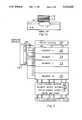
- FIG. 4illustrates a schematic diagram, in block form, of the physical organization of a nonvolatile memory array constructed in accordance with the FIG. 2 embodiment of this invention.
- FIG. 1aa nonvolatile array of memory cells, which is an integral part of a memory chip, is shown.
- Each cellis a floating-gate transistor 10 including a first electrode 11 (source), a second electrode 12 (drain), a floating-gate conductor 13 and a control electrode 14 (control gate).
- a cross-sectional view of a typical prior-art floating-gate transistor 10is illustrated in FIG. 1a as formed on a substrate SUB.
- Each of the control gate electrodes 14 in a row of cellsis connected to a wordline 15, and each of the plurality of wordlines 15 is connected to a wordline decoder 16.
- Each of the source electrodes 11 in a column of cellsis connected to one of a plurality of source-column lines 17, and each of the source-column lines 17 is connected through a first logic switch 18 to a driven source supply 19.
- Each of the drain electrodes 12 in a column of cellsis connected to one of a plurality of drain-column lines 20, and each of the drain-column lines 20 is connected through a second logic switch 21 to a drain-column decoder 22.
- the wordline decoder 16may function, in response to wordline-address signals on lines 23r, to place a preselected first programming voltage Vpp (approx. +18V) on a selected wordline 15, including the control-gate conductor 14 of the selected cell 10.
- Drain-column decoder 22functions, in response to bitline-address signals on lines 23d, to place a preselected second programming voltage (reference potential Vss or ground) on drain-column lines 20, which includes the drain region 12 of the selected cell 10.
- the wordline decoder 16may, optionally and in response to wordline-address signals on lines 23r, place a third preselected voltage Vhs (approx.
- Drain column decoder 22also functions to place a fourth preselected voltage, which may also be Vhs, on deselected drain-column lines 20. All source-column lines 17 are allowed to float by driven source supply 19.
- the positive voltage Vpp applied to the control gate 14 of the selected cell 10causes the semi-conductive source-drain path of the selected cell 10 to be conductive. Therefore, the source 11 of the selected cell 10 is at the same potential (Vss) as the drain 12 of that cell 10.
- the preselected second programming voltage Vssmust differ sufficiently from the first preselected programming voltage Vpp that excess electrons will migrate, perhaps by Fowler-Nordheim tunneling, to the floating-gate conductor 13 of the selected cell 10 and, as a result, program that selected floating-gate conductor 13.
- the third and fourth preselected Voltage (Vhs)should be placed on the deselected wordlines 15 and deselected drain-column lines 20 prior to placing both the first and second preselected voltages Vpp and Vss on their respective electrodes.
- the first programming voltagemay be placed on the control-gate conductors 14 in a gradual manner so as to reduce voltage-induced stress on the selected cell 10.
- the floating gate 13 of the selected cell 10will be charged with electrons, and the electrons in turn render the source-drain current path under the floating gate 13 of the cell 10 nonconductive, a state which is read as a "zero" bit.
- Non-programmed cellshave source-drain current paths under the floating gate 13 that remain conductive, and those cells are read as "one" bits.
- the driven source supply 19functions to apply a positive voltage Vcc (approx. +5V) to all the source-column lines 17.
- the drain-column decoder 22functions to leave all drain-column lines 20 floating.
- the wordline decoder 16functions to apply a high negative voltage Vee (approx. -11V) to all the wordlines 15. The excess electrons are removed from the floating gates 13 of programmed cells, perhaps by Fowler-Nordheim tunneling.
- the wordline decoder 16functions, in response to wordline-address signals on lines 23r, to apply a preselected positive voltage Vcc (approx. +5V) to the selected wordline 15, and to apply a low voltage (ground or Vss) to deselected wordlines 15.
- the drain-column decoder 22functions, in response to drain-column-address signals on lines 23d, to apply a preselected positive voltage Vsen (approx. +1.5V) to the selected drain-column line 20.
- the driven source supply 19functions to connect all source-column lines 17 to ground (or Vss).
- the conductive or nonconductive state of the cell connected to the selected drain-column line 20 and the selected wordline 15is detected by a sense amplifier (not shown) connected to the DATA OUT terminal.
- Read/Write/Erase circuit 24which in response to CONTROL SIGNALS 24a input from a microprocessor, not shown furnishes appropriate signals to wordline decoder 16, drain-column decoder 22 and driven source supply 19.
- the source regions 11 and drain regions 12 of memory cells 10may be interchanged for the various modes of operation.
- the Fowler-Nordheim tunnelingmay take place between a drain region 12 and floating-gate conductor 13 rather than between source region 11 and floating-gate conductor 13, as shown in FIG. 1. Therefore, the terms "source” and “drain” as used herein are considered interchangeable for each mode of operation.
- a typical large array of the type illustrated in FIG. 1may have perhaps thousands of rows and columns of memory cells 10.
- Each wordline 15 of the circuit of FIG. 1is separately connected to an output of wordline-decode circuit 16.
- the circuit elements of wordline-decode circuit 16may be distributed throughout the array to minimize the chip area required for conductors.
- the nonvolatile memory array of FIG. 1is segmented into a plurality of rows and columns of memory-cell segments 25.
- Each drain-column line 20 (bitline) of each segment 25is connected through a second logic switch 21, which is illustrated as a segment-select transistor, to external bitline 26.
- External bitline 26may be globally connected to common drain-column lines 20 of other segments 25.
- Each source-column line 17is connected through a first logic switch 18, which is illustrated as a field-effect transistor, to a driven common-source line 27.
- Each wordline 15may be parallel-connected to a common external wordline 28.
- the control electrodes, or gate terminals, of the second logic switches 21 in each segmentare connected to a drain-select signal terminal of segment-select decoder 29.
- the control terminals, or gates, of first logic switches 18are commonly connected to a source-select signal terminal of segment-select decoder 29.
- a nonvolatile memory arraymay be constructed with sixty-four segments 25, each comprising thirty-two wordlines 15 as indicated in FIG. 2.
- the corresponding wordlines 15 from each segment 25may be connected in parallel and driven by a set of thirty-two wordline decoders 16, which provide separate high negative voltage generators for the erase mode of operation.
- Each wordline 15, or set of connected wordlines 15,can be independently erased in a single erase cycle, or, alternatively, the entire chip may be erased in one cycle.
- the devicemay be programmed one byte at a time, or up to a full page (one wordline 15 of one segment 25) may be programmed in a single cycle using a bank of bitline latches 30 to provide the necessary data storage for page programming.
- bitline latches 30are set one at a time by input signals transmitted by drain column decoder 22 through drain-column lines 20. The data stored in bitline latches 30 are then programmed simultaneously into cells 10 in a row of a segment 25.
- each cell 10 of a segment 25may be formed between a local drain-column line 20 and local source-column line 17.
- the drain-column lines 20 and the source-column lines 17may be N+ diffusions that are buried in a semiconductor substrate of P+ type conductivity.
- First and second segment-select transistors 18 and 21may be N-channel field-effect transistors having sources and drains formed with the buried N+diffusions of the memory cells 10, allowing a compact layout for each segment. Because each segmented drain-column line 20 is relatively short, the drain-column line 20 capacitance is reduced and the speed of performance improved.
- a voltage(perhaps equal to the supply voltage Vcc) may be applied to the selected wordline 15 and the deselected wordlines 15 may be at ground. All of the sources 11 in all of the segments 25 are driven to ground (Vss).
- the selected drain-column line 20receives the necessary bias (Vsen) from the sense amplifier.
- an internally generated voltage of approximately eighteen volts (Vpp)is applied to the selected wordline 15, while an intermediate "half-select" potential (Vhs) is applied to the deselected wordlines 15.
- the source switches 18 of the selected segment 25are off or non-conductive, separating the source-column lines 17 from the driven source supply 19.
- the source switches 18 of the deselected segments 25are on, connecting the source-column lines to potential Vhs.
- the drain 12 of the cell 10 to be programmedis driven to ground (Vss), and the corresponding source 11 will follow by conduction.
- the drains 12 of deselected cells 10default to potential Vhs.
- a negative potential of approximately -11 volts (Vee)is applied to the selected wordline 15, or to all of the wordlines 15 for flash (or full-chip) erase.
- Veenegative potential
- Vccis applied to the deselected wordlines 15.
- a sector erase modemay be used to erase one row of cells 10 in a segment 25 or may be used to erase a row of cells 10 in several segments where those rows have commonly connected wordlines 15. All of the sources 11 are driven to potential Vcc during the erase mode of operation and all of the drains 12 are allowed to float. Segments 25 may be erased one row of memory cells 10 at a time.
- the memory cells 10 in that rowmay be tested to determine whether or not any memory cell 10 of that row is in an over-erased state.
- a cell 10 that is over-erasedhas a source-drain path that is conductive with no voltage on the control gate of that cell 10.
- Each row of cells 10may be individually inspected for over-erasure because the segment-select decoder 29 isolates cells 10 in different segments connected to commonly connected wordlines and also connected to commonly connected bitlines. If any memory cell 10 is found to be over-erased, the over-erased condition is removed before proceeding with the erasing procedure.
- One method for removing the over-erased conditionis to apply a partial programming voltage to the control electrode 14 of the over-erased cell lo to inject a small number of electrons into the floating gate 13.
- Another methodis to apply alternating, decreasing-magnitude, programming and erasing voltages to the over-erased memory cell 10 to neutralize the charge on the floating gate 13.
- the next row, or commonly connected rows, of memory cells 10may then be erased, and the method continued until all of the cells 10 in an array are erased, but not over-erased.
- FIG. 4An example of a physical organization of the memory array is illustrated in FIG. 4.
- the read portion 16r of the remote wordline decoderis located separately at one end (the top) of the columns of segments 25 of the array, while the program/erase portion 16pe is located separately at the other end (the bottom) of the columns of segments 25 of the array.
- the read portion 16r of the remote wordline decoderis illustrated as having one set of perhaps 32 output terminals (three are illustrated)
- portion 16amay be constructed of a plurality of wordline decoders 16r, each having 32 output terminals and serving a pair of segment columns, the identical wordline decoders 16r operating in parallel.
- a wordline decoder circuit with separate parts for reading, programming and erasing operationsis described in U.S. patent application Ser. No. 07/513,534, filed Apr. 23, 1990, now abandoned in favor of continuation application Ser. No. 07/787,706, filed Nov. 4, 1991 and also assigned to Texas Instruments Incorporated.
- Periodic breaks in the arrayprovide for the segment select decoders that are required to enable the selected segment and also provide for routing channels that are required for connecting the wordline decoders 16r and 16pe to the wordlines 15.
Landscapes
- Engineering & Computer Science (AREA)
- Microelectronics & Electronic Packaging (AREA)
- Read Only Memory (AREA)
Abstract
Description
This application a continuation of application Ser. No. 07/518,394, filed May 23, 1990, now abandoned.
This invention relates to segmentation of memory arrays and, in particular, to segmentation of nonvolatile memory arrays such as electrically-erasable, electrically-programmable, read-only-memories (EEPROMs). In particular, this invention relates to a segmented array architecture having buried-bitline, segment-select transistors, having remote wordline decoders, and having segment decoders.
The speed of access to information contained in non-volatile memory arrays is largely dependent on the capacitance of the bitlines and the wordlines. Those capacitances are a function of choices that include the lengths of the bitlines and wordlines, pitch, chip/bar size and aspect ratio, and process parameters. In general, small capacitances are required for fast access time during operation of memory arrays. Conventional segmentation with separate driver circuitry for each segmented wordline and for each segmented bitline is generally impermissible because that method of reducing the access time delay requires an unacceptable increase in driver circuit area on integrated circuit chips.
Increased component density in memory arrays has led to higher bitline capacitance. One way of decreasing that capacitance has been to segment the bitlines of arrays. Segmentation of bitlines of a memory array is described in U.S. patent application Ser. No. 07/402,402, filed Sep. 5, 1989 (issued Jun. 11, 1991 as U.S. Pat. No. 5,023,837) and also assigned to Texas Instruments Incorporated.
In high-density, flash-erase-type EEPROMs, reduced wordline pitch and an increased number of voltages applied to the wordlines have created difficulty in laying out the rather complicated wordline decoder and other control circuits efficiently. A need has arisen for a segmented array that allows a fewer number of wordline decoders, which are remotely located from the wordlines and which have a more-sophisticated design.
This invention describes an alternative to the array segmentation described in the aforementioned U.S. patent application Ser. No. 07/402,402, filed Sep. 5, 1989 (issued Jun. 11, 1991 as U.S. Pat. No. 5,023,387) and also assigned to Texas Instruments Incorporated. That application describes segmentation of bitlines for connection to bitline decoding circuitry while, at the same time, combining wordlines of the various segments for connection to wordline decoding circuitry. The segmentation and decoding connection described in that application permits faster speed of operation with minimal or no area penalty. The area penalty is avoided by driving common wordlines in each of the segments, effectively increasing the wordline pitch at the wordline decoder, while at the same time decreasing the number of wordline decoders required.
In this invention, the wordline decode system of the entire array is split into three smaller decoding subsystems (a Read-Mode Wordline Decode Subsystem, a Program/Erase-Mode Decode Subsystem and a Segment-Select Decode Subsystem). Fewer inputs are connected to each decoding subsystem. Because the Read-Mode Decoder circuitry and the Program/Erase-Mode Decoder circuitry are separated, the Read-Mode Decoder circuitry may be made optimum for high speed access and the Program/Erase-Mode Decoder circuitry may be made optimum for high voltage operation. Buried-bitline segment-select transistors reduce the area required for those transistors, as compared to the area required in known prior-art decoder systems.
The invention includes methods for erasing and for programming segmented arrays of such cells.
The novel features of this invention are set forth in the appended claims. The invention, its features, and its advantages are described below in conjunction with the following drawings:
FIG. 1a illustrates a schematic diagram, in partial block form, of a prior-art, nonvolatile memory array.
FIG. 1b illustrates a cross-sectional view of a typical prior-art memory cell formed on a substrate.
FIG. 2 illustrates a schematic diagram, in block form, of electrical connections for the logical organization of a nonvolatile memory array constructed in accordance with an embodiment of this invention.
FIG. 3 illustrates a schematic diagram, in partial block form, of the arrangement-of nonvolatile memory cells within a segment of the diagram of FIG. 2.
FIG. 4 illustrates a schematic diagram, in block form, of the physical organization of a nonvolatile memory array constructed in accordance with the FIG. 2 embodiment of this invention.
Referring to FIG. 1a, a nonvolatile array of memory cells, which is an integral part of a memory chip, is shown. Each cell is a floating-gatetransistor 10 including a first electrode 11 (source), a second electrode 12 (drain), a floating-gateconductor 13 and a control electrode 14 (control gate). A cross-sectional view of a typical prior-art floating-gatetransistor 10 is illustrated in FIG. 1a as formed on a substrate SUB. Each of thecontrol gate electrodes 14 in a row of cells is connected to awordline 15, and each of the plurality ofwordlines 15 is connected to awordline decoder 16. Each of thesource electrodes 11 in a column of cells is connected to one of a plurality of source-column lines 17, and each of the source-column lines 17 is connected through afirst logic switch 18 to a drivensource supply 19. Each of thedrain electrodes 12 in a column of cells is connected to one of a plurality of drain-column lines 20, and each of the drain-column lines 20 is connected through asecond logic switch 21 to a drain-column decoder 22.
In a write or program mode of operation, thewordline decoder 16 may function, in response to wordline-address signals onlines 23r, to place a preselected first programming voltage Vpp (approx. +18V) on aselected wordline 15, including thecontrol-gate conductor 14 of theselected cell 10. Drain-column decoder 22 functions, in response to bitline-address signals onlines 23d, to place a preselected second programming voltage (reference potential Vss or ground) on drain-column lines 20, which includes thedrain region 12 of theselected cell 10. Thewordline decoder 16 may, optionally and in response to wordline-address signals onlines 23r, place a third preselected voltage Vhs (approx. +7V) on deselectedwordlines 15, includingcontrol-gate conductors 14 ofdeselected cells 10. The third preselected, or "half-select" voltage Vhs, should be sufficiently close to the second programming voltage that the floating-gateconductors 13 associated with thedeselected wordlines 15 will not be programmed as a result, but should be sufficiently high that stress will be reduced across any tunnelling windows TW of cells in deselectedwordlines 15, thereby avoiding de-programming of pre-programmed cells.Drain column decoder 22 also functions to place a fourth preselected voltage, which may also be Vhs, on deselected drain-column lines 20. All source-column lines 17 are allowed to float by drivensource supply 19. The positive voltage Vpp applied to thecontrol gate 14 of theselected cell 10 causes the semi-conductive source-drain path of theselected cell 10 to be conductive. Therefore, thesource 11 of theselected cell 10 is at the same potential (Vss) as thedrain 12 of thatcell 10. The preselected second programming voltage Vss must differ sufficiently from the first preselected programming voltage Vpp that excess electrons will migrate, perhaps by Fowler-Nordheim tunneling, to thefloating-gate conductor 13 of theselected cell 10 and, as a result, program that selected floating-gateconductor 13. The third and fourth preselected Voltage (Vhs) should be placed on thedeselected wordlines 15 and deselected drain-column lines 20 prior to placing both the first and second preselected voltages Vpp and Vss on their respective electrodes. The first programming voltage may be placed on thecontrol-gate conductors 14 in a gradual manner so as to reduce voltage-induced stress on theselected cell 10. Thefloating gate 13 of theselected cell 10 will be charged with electrons, and the electrons in turn render the source-drain current path under thefloating gate 13 of thecell 10 nonconductive, a state which is read as a "zero" bit. Non-programmed cells have source-drain current paths under thefloating gate 13 that remain conductive, and those cells are read as "one" bits.
During a flash-erase mode of operation, the driven source supply 19 functions to apply a positive voltage Vcc (approx. +5V) to all the source-column lines 17. The drain-column decoder 22 functions to leave all drain-column lines 20 floating. Thewordline decoder 16 functions to apply a high negative voltage Vee (approx. -11V) to all thewordlines 15. The excess electrons are removed from the floatinggates 13 of programmed cells, perhaps by Fowler-Nordheim tunneling.
In the read mode of operation, thewordline decoder 16 functions, in response to wordline-address signals onlines 23r, to apply a preselected positive voltage Vcc (approx. +5V) to the selectedwordline 15, and to apply a low voltage (ground or Vss) to deselectedwordlines 15. The drain-column decoder 22 functions, in response to drain-column-address signals onlines 23d, to apply a preselected positive voltage Vsen (approx. +1.5V) to the selected drain-column line 20. The drivensource supply 19 functions to connect all source-column lines 17 to ground (or Vss). The conductive or nonconductive state of the cell connected to the selected drain-column line 20 and the selectedwordline 15 is detected by a sense amplifier (not shown) connected to the DATA OUT terminal.
The mode of operation is controlled by Read/Write/Erasecircuit 24, which in response to CONTROLSIGNALS 24a input from a microprocessor, not shown furnishes appropriate signals to wordlinedecoder 16, drain-column decoder 22 and drivensource supply 19.
As is well-known, thesource regions 11 anddrain regions 12 ofmemory cells 10 may be interchanged for the various modes of operation. For example, the Fowler-Nordheim tunneling may take place between adrain region 12 andfloating-gate conductor 13 rather than betweensource region 11 andfloating-gate conductor 13, as shown in FIG. 1. Therefore, the terms "source" and "drain" as used herein are considered interchangeable for each mode of operation.
For convenience, a table of read, write and erase voltages s given in the TABLE I below:
TABLE I ______________________________________ Read Program Flash Erase ______________________________________ Selected Wordline 5 V 18 V -11 V (All) Deselected Wordlines 0 V 7 V Source-Column Lines 0 V Float 5 V Selected Drain Column 1.5 V 0 V Float (All) Deselected Drain Column 0 V 7 V ______________________________________
A typical large array of the type illustrated in FIG. 1 may have perhaps thousands of rows and columns ofmemory cells 10.
Eachwordline 15 of the circuit of FIG. 1 is separately connected to an output of wordline-decode circuit 16. The circuit elements of wordline-decode circuit 16 may be distributed throughout the array to minimize the chip area required for conductors.
Referring to FIGS. 2 and 3, the nonvolatile memory array of FIG. 1 is segmented into a plurality of rows and columns of memory-cell segments 25. Each drain-column line 20 (bitline) of eachsegment 25 is connected through asecond logic switch 21, which is illustrated as a segment-select transistor, toexternal bitline 26.External bitline 26 may be globally connected to common drain-column lines 20 ofother segments 25. Each source-column line 17 is connected through afirst logic switch 18, which is illustrated as a field-effect transistor, to a driven common-source line 27. Eachwordline 15 may be parallel-connected to a commonexternal wordline 28. The control electrodes, or gate terminals, of the second logic switches 21 in each segment are connected to a drain-select signal terminal of segment-select decoder 29. The control terminals, or gates, of first logic switches 18 are commonly connected to a source-select signal terminal of segment-select decoder 29.
For example, a nonvolatile memory array may be constructed with sixty-foursegments 25, each comprising thirty-twowordlines 15 as indicated in FIG. 2. The corresponding wordlines 15 from eachsegment 25 may be connected in parallel and driven by a set of thirty-twowordline decoders 16, which provide separate high negative voltage generators for the erase mode of operation. Eachwordline 15, or set ofconnected wordlines 15, can be independently erased in a single erase cycle, or, alternatively, the entire chip may be erased in one cycle. The device may be programmed one byte at a time, or up to a full page (onewordline 15 of one segment 25) may be programmed in a single cycle using a bank of bitline latches 30 to provide the necessary data storage for page programming. Using the page mode, bitline latches 30 are set one at a time by input signals transmitted bydrain column decoder 22 through drain-column lines 20. The data stored in bitline latches 30 are then programmed simultaneously intocells 10 in a row of asegment 25.
Referring specifically to FIGS. 1a and 3, eachcell 10 of asegment 25 may be formed between a local drain-column line 20 and local source-column line 17. The drain-column lines 20 and the source-column lines 17 may be N+ diffusions that are buried in a semiconductor substrate of P+ type conductivity. First and second segment-select transistors memory cells 10, allowing a compact layout for each segment. Because each segmented drain-column line 20 is relatively short, the drain-column line 20 capacitance is reduced and the speed of performance improved.
During the read mode of operation, a voltage (perhaps equal to the supply voltage Vcc) may be applied to the selectedwordline 15 and the deselectedwordlines 15 may be at ground. All of thesources 11 in all of thesegments 25 are driven to ground (Vss). The selected drain-column line 20 receives the necessary bias (Vsen) from the sense amplifier.
During the programming mode of operation, an internally generated voltage of approximately eighteen volts (Vpp) is applied to the selectedwordline 15, while an intermediate "half-select" potential (Vhs) is applied to the deselectedwordlines 15. The source switches 18 of the selectedsegment 25 are off or non-conductive, separating the source-column lines 17 from the drivensource supply 19. The source switches 18 of the deselectedsegments 25 are on, connecting the source-column lines to potential Vhs. Thedrain 12 of thecell 10 to be programmed is driven to ground (Vss), and thecorresponding source 11 will follow by conduction. Thedrains 12 of deselectedcells 10 default to potential Vhs.
During the erase mode of operation, a negative potential of approximately -11 volts (Vee) is applied to the selectedwordline 15, or to all of thewordlines 15 for flash (or full-chip) erase. In a sector erase mode, potential Vcc is applied to the deselectedwordlines 15. A sector erase mode may be used to erase one row ofcells 10 in asegment 25 or may be used to erase a row ofcells 10 in several segments where those rows have commonly connectedwordlines 15. All of thesources 11 are driven to potential Vcc during the erase mode of operation and all of thedrains 12 are allowed to float.Segments 25 may be erased one row ofmemory cells 10 at a time. After erasure of a row, thememory cells 10 in that row may be tested to determine whether or not anymemory cell 10 of that row is in an over-erased state. Acell 10 that is over-erased has a source-drain path that is conductive with no voltage on the control gate of thatcell 10. Each row ofcells 10 may be individually inspected for over-erasure because the segment-select decoder 29isolates cells 10 in different segments connected to commonly connected wordlines and also connected to commonly connected bitlines. If anymemory cell 10 is found to be over-erased, the over-erased condition is removed before proceeding with the erasing procedure. One method for removing the over-erased condition is to apply a partial programming voltage to thecontrol electrode 14 of the over-erased cell lo to inject a small number of electrons into the floatinggate 13. Another method is to apply alternating, decreasing-magnitude, programming and erasing voltages to theover-erased memory cell 10 to neutralize the charge on the floatinggate 13. After removal of the over-erased condition, the next row, or commonly connected rows, ofmemory cells 10 may then be erased, and the method continued until all of thecells 10 in an array are erased, but not over-erased.
The read, program and erase modes of operation of the array are detailed in Table II below:
TABLE II ______________________________________ Erase Read Program Sector Chip Common Source Vss Vhs Vcc Vcc ______________________________________ Selected Segment Drain-Select Signal ON ON OFF (All) OFF (All) Source-Select ON OFF ON (All) ON (All) Signal Selected Word- Vcc Vpp Vee Vee (All) line(s) Deselected Word- Vss Vhs Vcc (None) lines Selected Drain Line Vsen Vss Float (All) Float (All) Deselected Drain Float Vhs (None) (None) Lines Deselected Seg- (None) (None) ments Drain-Select Signal OFF OFF Source-Select ON ON Signal All Drain Lines Float Vhs ______________________________________
An example of a physical organization of the memory array is illustrated in FIG. 4. The readportion 16r of the remote wordline decoder is located separately at one end (the top) of the columns ofsegments 25 of the array, while the program/erase portion 16pe is located separately at the other end (the bottom) of the columns ofsegments 25 of the array. While the readportion 16r of the remote wordline decoder is illustrated as having one set of perhaps 32 output terminals (three are illustrated), portion 16a, may be constructed of a plurality of wordline decoders 16r, each having 32 output terminals and serving a pair of segment columns, theidentical wordline decoders 16r operating in parallel. A wordline decoder circuit with separate parts for reading, programming and erasing operations is described in U.S. patent application Ser. No. 07/513,534, filed Apr. 23, 1990, now abandoned in favor of continuation application Ser. No. 07/787,706, filed Nov. 4, 1991 and also assigned to Texas Instruments Incorporated.
Periodic breaks in the array provide for the segment select decoders that are required to enable the selected segment and also provide for routing channels that are required for connecting thewordline decoders 16r and 16pe to thewordlines 15.
While this invention has been described with respect to an illustrative embodiment, this description is not intended to be construed in a limiting sense. Upon reference to this description, various modifications of the illustrative embodiment, as well as other embodiments of the invention, will be apparent to persons skilled in the art. It is contemplated that the appended claims will cover any such modifications or embodiments that fall within the scope of the invention.
Claims (30)
1. A memory array comprising
a plurality of segments of memory cells, each segment including
a plurality of memory cells arranged in rows and columns, each memory cell including a control electrode, a first electrode, a second electrode, and a current path between the first and second electrodes;
a plurality of wordlines, control electrodes of memory cells in the same row being connected to a respective one of said wordlines;
a plurality of source-column lines, first electrodes of memory cells in the same column being connected to a corresponding one of said source-column lines;
a plurality of drain-column lines, second electrodes of memory cells in the same column being connected to an associated one of said drain-column lines;
a first wordline decoder circuit for selecting and accessing said wordlines;
a drain-column decoder circuit for selecting and accessing said drain-column lines, said drain-column decoder circuit having a plurality of output terminals;
a driven source supply for supplying electric potentials to said source-column lines, said driven source supply having at least one output terminal;
a segment-select decoder circuit having a drain-select terminal and a source-select terminal;
a first logic switch connected between each source-column line and said at least one output terminal of said driven source supply, each first logic switch having a control electrode, each control electrode of each first logic switch in the same segment being connected to said source-select terminal of said segment-select decoder circuit;
a second logic switch connected between each drain-column line and one of said plurality of output terminals of said drain-column decoder circuit, each second logic switch having a control electrode, each control electrode of each second logic switch in the same segment being connected to said drain-select terminal of said segment-select decoder circuit.
2. The memory array of claim 1, wherein each wordline of each segment is connected to a wordline of at least one other segment.
3. The memory array of claim 1, wherein each drain-column line of each segment is connected to a drain-column line of at least one other segment.
4. The memory array of claim 1, wherein said segments are arranged in columns, and wherein said segment-select decoder circuit is located adjacent one of said columns of segments.
5. The memory array of claim 1, wherein said first wordline decoder circuit selects and accesses said wordlines during reading of said memory cells.
6. The memory array of claim 1, wherein said first wordline decoder circuit selects and accesses said wordlines during reading of said memory cells and wherein said first wordline decoder circuit includes identical subcircuits, each of said subcircuits being connected to at least one of said segments.
7. The memory array of claim 1, wherein said first wordline decider circuit selects and accesses said wordlines during reading of said memory cells and wherein said memory array includes a second wordline decoder circuit that selects and accesses said wordlines during programming of said memory cells.
8. The memory array of claim 1, wherein said first wordline decoder circuit selects and accesses said wordlines during reading of said memory cells, wherein said memory array includes a second wordline decoder circuit that selects and accesses said wordlines during programming of said memory cells, and wherein said first wordline decoder circuit and said second wordline decoder circuit are located separately.
9. The memory array of claim 1, wherein said segments are arranged in columns, wherein said first wordline decoder circuit selects and accesses said wordlines during reading of said memory cells, wherein said memory array includes a second wordline decoder circuit that selects and accesses said wordlines during programming of said memory cells, and wherein said first wordline decoder circuit is located at one end of said columns of segments and wherein said second wordline decoder circuit is located at the other end of said columns of segments.
10. The memory array of claim 1, wherein each first logic switch is a field-effect transistor and each control electrode of each first logic switch is a control-gate terminal of a corresponding field-effect transistor.
11. The memory array of claim 1, wherein each first logic switch is a field-effect transistor located at one end of each source-column line, wherein each source-column line is a buried diffusion, and wherein a source and a drain of each field-effect transistor are buried diffusions incorporated in each source-column-line diffusion.
12. The memory array of claim 1, wherein each second logic switch is a field-effect transistor and wherein each control electrode of each second logic switch is a control-gate terminal of a corresponding field-effect transistor.
13. The memory array of claim 1, wherein each second logic switch is a field-effect transistor located at one end of each drain-column line, wherein each drain-column line is a buried diffusion, and wherein a source and a drain of each field-effect transistor are buried diffusions incorporated in each drain-column-line diffusion.
14. A non-volatile memory array comprising:
a drain-column decoder having a plurality of output terminals;
a driven source supply having at least one output terminal;
a segment-select circuit having a source-select signal terminal and having a drain-select signal terminal;
a first wordline-decoder circuit having a plurality of output terminals;
a plurality of rows and columns of segments, each segment including:
a plurality of memory cells arranged in rows and columns, each memory cell including a control electrode, a first electrode, a second electrode, and a current path between said first and second electrodes;
a plurality of wordlines, each wordline connected to control electrodes of memory cells in a respective row of memory cells and each wordline connected to a corresponding one of said output terminals of said first wordline decoder circuit;
a plurality of source-column lines and a plurality of drain-column lines, each source-column line connected to the first electrode of each memory cell in an associated column of said memory cells and each drain-column line connected to the second electrode of each memory cell in an associated column of said memory cells;
first logic switches respectively connecting each source-column line to said terminal of said driven source supply, each first logic switch having a control electrode, each control electrode of each first logic switch being connected to said source-selected signal terminal of said segment select circuit; and
second logic switches respectively connecting each drain-column line to a corresponding one of said terminals of said drain-column decoder, each second logic switch having a control electrode, each control electrode of each second logic switch being connected to said drain-select signal terminal of said segment select circuit.
15. The memory array of claim 14, wherein each wordline of a segment is connected to a wordline of at least one other segment.
16. The memory array of claim 14, wherein each drain-column line of each segment is connected to a drain-column line of at least one other segment.
17. The memory array of claim 14, wherein said segments are arranged in columns, and wherein said segment-select decoder circuit is located adjacent one of said columns of segment.
18. The memory array of claim 14, wherein said first wordline-decoder circuit selects and accesses said wordlines for reading said memory cells.
19. The memory array of claim 14, wherein said first wordline-decoder circuit selects and accesses said wordlines for reading said memory cells and wherein said first wordline-decoder circuit includes identical subcircuits, each of said subcircuits connected to at least one wordline of one of said segments.
20. The memory array of claim 14, wherein said first wordline-decoder circuit selects and accesses said wordlines for reading said memory cells and wherein said memory array includes a second wordline-decoder circuit that selects and accesses said wordlines for at least one of programming and erasing said memory cells.
21. The memory array of claim 14, wherein said first wordline-decoder circuit selects and accesses said wordlines for reading said memory cells, wherein said memory array includes a second wordline-decoder circuit that selects and accesses said wordlines for at least one of programming and erasing said memory cells, and wherein said first wordline decoder circuit and said second wordline decoder circuit are separated.
22. The memory array of claim 14, wherein said segment ar arranged in columns, wherein said first wordline-decoder circuit selects and accesses said wordlines for reading said memory cells, wherein said memory array includes a second wordline-decoder circuit that functions to select and access said wordlines for programming said memory cells, wherein said first wordline-decoder circuit is located at one end of said columns of segments, and wherein said second wordline-decoder circuit is located at the other end of said columns of segment.
23. The memory array of claim 14, wherein each first logic switch is a field-effect transistor and the control electrode of each first logic switch is a control-gate terminal of a corresponding field-effect transistor.
24. The memory array of claim 14, wherein each first logic switch is a field-effect transistor located at one end of each source-column line, wherein each source-column line is a buried diffusion, and wherein a source and a drain of each field-effect transistor are buried diffusions incorporated in each source-column-line diffusion.
25. The memory array of claim 14, wherein each second logic switch is a field-effect transistor and wherein the control electrode of each second logic switch is a control gate terminal of a corresponding field-effect transistor.
26. The memory array of claim 14, wherein each second logic switch is a field-effect transistor located at one end of each drain-column line, wherein each drain-column line is a buried diffusion, and wherein a source and a drain of each field-effect transistor are buried diffusions incorporated in each drain-column-line diffusion.
27. A method for programming a memory array including segments of nonvolatile memory cells, each segment having source-column lines, wordlines and drain-column lines, said memory cells arranged in rows and columns, each memory cell having a first electrode, a second electrode, a part of a semiconductor substrate between the first and second electrodes, a control electrode, a floating gate conductor insulated from and located between the control electrode and said part of said semiconductor substrate, a tunneling window between the first electrode and the floating gate, each control electrode connected to a wordline of said memory array, each first electrode connected to one of said source-column lines, each second electrode connected to one of said drain-column lines, the method comprising:
placing a first voltage on all of the source-column lines of a non-selected segment;
placing said first voltage on all of the drain-column lines of said non-selected segment;
allowing all of said source-column lines of a selected segment of said memory array to electrically float;
placing a second voltage on a selected wordline of said selected segment; and
placing a third voltage on a selected drain-column line of said selected segment;
the difference in voltage between said second voltage and said third voltage being sufficient to cause electrons to migrate across the tunneling window of a memory cell connected to said selected wordline and said selected drain-column line to program that memory cell, said first voltage being intermediate to said second voltage and said third voltage.
28. The method of claim 27, wherein said second voltage is applied to said selected wordline in a gradual manner.
29. The method of claim 27, wherein a voltage intermediate to said second voltage and said third voltage is applied to nonselected wordlines of said memory array.
30. The method of claim 27, wherein said array includes at least one latch circuit connected to one of said drain-column lines, wherein said third voltage is stored in said at lest one latch circuit and wherein more than one memory cell in said selected segment is programmed simultaneously.
Priority Applications (1)
| Application Number | Priority Date | Filing Date | Title |
|---|---|---|---|
| US07/790,122US5313432A (en) | 1990-05-23 | 1991-11-12 | Segmented, multiple-decoder memory array and method for programming a memory array |
Applications Claiming Priority (2)
| Application Number | Priority Date | Filing Date | Title |
|---|---|---|---|
| US51839490A | 1990-05-23 | 1990-05-23 | |
| US07/790,122US5313432A (en) | 1990-05-23 | 1991-11-12 | Segmented, multiple-decoder memory array and method for programming a memory array |
Related Parent Applications (1)
| Application Number | Title | Priority Date | Filing Date |
|---|---|---|---|
| US51839490AContinuation | 1990-05-23 | 1990-05-23 |
Publications (1)
| Publication Number | Publication Date |
|---|---|
| US5313432Atrue US5313432A (en) | 1994-05-17 |
Family
ID=24063750
Family Applications (1)
| Application Number | Title | Priority Date | Filing Date |
|---|---|---|---|
| US07/790,122Expired - LifetimeUS5313432A (en) | 1990-05-23 | 1991-11-12 | Segmented, multiple-decoder memory array and method for programming a memory array |
Country Status (1)
| Country | Link |
|---|---|
| US (1) | US5313432A (en) |
Cited By (70)
| Publication number | Priority date | Publication date | Assignee | Title |
|---|---|---|---|---|
| US5408429A (en)* | 1992-04-24 | 1995-04-18 | Nippon Steel Corporation | Method of altering a non-volatile semiconductor memory device |
| US5467307A (en)* | 1993-10-12 | 1995-11-14 | Texas Instruments Incorporated | Memory array utilizing low voltage Fowler-Nordheim Flash EEPROM cell |
| US5473563A (en)* | 1993-01-13 | 1995-12-05 | Samsung Electronics Co., Ltd. | Nonvolatile semiconductor memory |
| US5554868A (en)* | 1990-12-26 | 1996-09-10 | Mitsubishi Denki Kabushiki Kaisha | Non-volatile semiconductor memory device |
| US5583808A (en)* | 1994-09-16 | 1996-12-10 | National Semiconductor Corporation | EPROM array segmented for high performance and method for controlling same |
| US5602775A (en)* | 1995-03-15 | 1997-02-11 | National Semiconductor Corporation | Flash EEPROM Memory system for low voltage operation and method |
| US5636168A (en)* | 1994-10-24 | 1997-06-03 | Nec Corporation | Method for testing a nonvolatile semiconductor memory device |
| US5646886A (en)* | 1995-05-24 | 1997-07-08 | National Semiconductor Corporation | Flash memory having segmented array for improved operation |
| US5732022A (en)* | 1992-03-31 | 1998-03-24 | Kabushiki Kaisha Toshiba | Non-volatile semiconductor memory device |
| US5745422A (en)* | 1996-11-12 | 1998-04-28 | International Business Machines Corporation | Cross-coupled bitline segments for generalized data propagation |
| US5764589A (en)* | 1997-03-28 | 1998-06-09 | International Business Machines Corporation | Array row and column decoder apparatus and method |
| US5784325A (en)* | 1994-07-25 | 1998-07-21 | Sony Corporation | Semiconductor nonvolatile memory device |
| US5808935A (en)* | 1995-01-07 | 1998-09-15 | Samsung Electronics Co., Ltd. | Common source line driving circuit for use in nonvolatile semiconductor memories |
| US5903022A (en)* | 1995-04-12 | 1999-05-11 | Kabushiki Kaisha Toshiba | Semiconductor memory device having improved word line arrangement in a memory cell array |
| EP0823117A4 (en)* | 1995-04-28 | 1999-06-02 | Intel Corp | Nonvolatile memory blocking architecture |
| US5946236A (en)* | 1997-03-31 | 1999-08-31 | Sanyo Electric Co., Ltd. | Non-volatile semiconductor memory device and method for writing information therein |
| US6556503B2 (en) | 2001-08-21 | 2003-04-29 | Micron Technology, Inc. | Methods and apparatus for reducing decoder area |
| US20040109354A1 (en)* | 2002-12-06 | 2004-06-10 | Sandisk Corporation | Current-limited latch |
| US20050194614A1 (en)* | 2004-02-19 | 2005-09-08 | Eggers Georg E. | Integrated semiconductor memory and method for electrically stressing an integrated semiconductor memory |
| US20060203587A1 (en)* | 2005-03-11 | 2006-09-14 | Yan Li | Partition of non-volatile memory array to reduce bit line capacitance |
| US20060209599A1 (en)* | 1992-07-06 | 2006-09-21 | Masataka Kato | Nonvolatile semiconductor memory |
| US20070257291A1 (en)* | 2006-05-02 | 2007-11-08 | Serguei Okhonin | Semiconductor memory cell and array using punch-through to program and read same |
| US20070297252A1 (en)* | 2006-06-26 | 2007-12-27 | Anant Pratap Singh | Integrated circuit having memory array including ECC and/or column redundancy, and method of programming, controlling and/or operating same |
| US20080013359A1 (en)* | 2006-07-11 | 2008-01-17 | David Fisch | Integrated circuit including memory array having a segmented bit line architecture and method of controlling and/or operating same |
| US20080180995A1 (en)* | 2007-01-26 | 2008-07-31 | Serguei Okhonin | Semiconductor Device With Electrically Floating Body |
| US20080237714A1 (en)* | 2007-03-29 | 2008-10-02 | Pierre Fazan | Manufacturing Process for Zero-Capacitor Random Access Memory Circuits |
| US20080298139A1 (en)* | 2007-05-30 | 2008-12-04 | David Fisch | Integrated circuit having voltage generation circuitry for memory cell array, and method of operating and /or controlling same |
| US20090016101A1 (en)* | 2007-06-01 | 2009-01-15 | Serguei Okhonin | Reading Technique for Memory Cell With Electrically Floating Body Transistor |
| US20090080244A1 (en)* | 2007-09-17 | 2009-03-26 | Eric Carman | Refreshing Data of Memory Cells with Electrically Floating Body Transistors |
| US20090141550A1 (en)* | 2006-04-07 | 2009-06-04 | Eric Carman | Memory Array Having a Programmable Word Length, and Method of Operating Same |
| US20090146219A1 (en)* | 2007-12-11 | 2009-06-11 | Danngis Liu | Integrated circuit having memory cell array, and method of manufacturing same |
| US20090200612A1 (en)* | 2008-02-08 | 2009-08-13 | Viktor Koldiaev | Integrated Circuit Having Memory Cells Including Gate Material Having High Work Function, and Method of Manufacturing Same |
| US20090251958A1 (en)* | 2008-04-04 | 2009-10-08 | Philippe Bauser | Read circuitry for an integrated circuit having memory cells and/or a memory cell array, and method of operating same |
| US20100075471A1 (en)* | 2008-09-25 | 2010-03-25 | Innovative Silicon Isi Sa | Recessed Gate Silicon-On-Insulator Floating Body Device With Self-Aligned Lateral Isolation |
| US20100085806A1 (en)* | 2008-10-02 | 2010-04-08 | Ping Wang | Techniques for reducing a voltage swing |
| US20100091586A1 (en)* | 2008-10-15 | 2010-04-15 | Innovative Silicon Isi Sa | Techniques for simultaneously driving a plurality of source lines |
| US20100110816A1 (en)* | 2008-11-05 | 2010-05-06 | Innovative Silicon Isi Sa | Techniques for block refreshing a semiconductor memory device |
| US20100210075A1 (en)* | 2009-02-18 | 2010-08-19 | Innovative Silicon Isi Sa | Techniques for providing a source line plane |
| US20100224924A1 (en)* | 2009-03-04 | 2010-09-09 | Innovative Silicon Isi Sa | Techniques for forming a contact to a buried diffusion layer in a semiconductor memory device |
| US20100259964A1 (en)* | 2009-03-31 | 2010-10-14 | Innovative Silicon Isi Sa | Techniques for providing a semiconductor memory device |
| US20100271880A1 (en)* | 2009-04-27 | 2010-10-28 | Innovative Silicon Isi Sa | Techniques for controlling a direct injection semiconductor memory device |
| US20100277982A1 (en)* | 2009-04-30 | 2010-11-04 | Innovative Silicon Isi Sa | Semiconductor device with floating gate and electrically floating body |
| US20110019481A1 (en)* | 2009-07-27 | 2011-01-27 | Innovative Silicon Isi Sa | Techniques for providing a direct injection semiconductor memory device |
| US20110058436A1 (en)* | 2009-09-04 | 2011-03-10 | Innovative Silicon Isi Sa | Techniques for sensing a semiconductor memory device |
| US20110199848A1 (en)* | 2010-02-12 | 2011-08-18 | Innovative Silicon Isi Sa | Techniques for controlling a semiconductor memory device |
| US8014195B2 (en) | 2008-02-06 | 2011-09-06 | Micron Technology, Inc. | Single transistor memory cell |
| US20110216608A1 (en)* | 2010-03-05 | 2011-09-08 | Innovative Silicon Isi Sa | Techniques for reading from and/or writing to a semiconductor memory device |
| US20110216617A1 (en)* | 2010-03-04 | 2011-09-08 | Innovative Silicon Isi Sa | Techniques for sensing a semiconductor memory device |
| US20110216605A1 (en)* | 2010-03-04 | 2011-09-08 | Innovative Silicon Isi Sa | Techniques for providing a semiconductor memory device having hierarchical bit lines |
| US8174881B2 (en) | 2009-11-24 | 2012-05-08 | Micron Technology, Inc. | Techniques for reducing disturbance in a semiconductor device |
| US8213226B2 (en) | 2008-12-05 | 2012-07-03 | Micron Technology, Inc. | Vertical transistor memory cell and array |
| US8310893B2 (en) | 2009-12-16 | 2012-11-13 | Micron Technology, Inc. | Techniques for reducing impact of array disturbs in a semiconductor memory device |
| US8411524B2 (en) | 2010-05-06 | 2013-04-02 | Micron Technology, Inc. | Techniques for refreshing a semiconductor memory device |
| US8498157B2 (en) | 2009-05-22 | 2013-07-30 | Micron Technology, Inc. | Techniques for providing a direct injection semiconductor memory device |
| US8531878B2 (en) | 2011-05-17 | 2013-09-10 | Micron Technology, Inc. | Techniques for providing a semiconductor memory device |
| US8537610B2 (en) | 2009-07-10 | 2013-09-17 | Micron Technology, Inc. | Techniques for providing a semiconductor memory device |
| US8536628B2 (en) | 2007-11-29 | 2013-09-17 | Micron Technology, Inc. | Integrated circuit having memory cell array including barriers, and method of manufacturing same |
| US8547738B2 (en) | 2010-03-15 | 2013-10-01 | Micron Technology, Inc. | Techniques for providing a semiconductor memory device |
| US8605525B2 (en)* | 2010-11-23 | 2013-12-10 | Macronix International Co., Ltd. | System and method for testing for defects in a semiconductor memory array |
| US8618614B2 (en) | 2010-12-14 | 2013-12-31 | Sandisk 3D Llc | Continuous mesh three dimensional non-volatile storage with vertical select devices |
| US8773933B2 (en) | 2012-03-16 | 2014-07-08 | Micron Technology, Inc. | Techniques for accessing memory cells |
| US8873283B2 (en) | 2005-09-07 | 2014-10-28 | Micron Technology, Inc. | Memory cell and memory cell array having an electrically floating body transistor, and methods of operating same |
| US9165933B2 (en) | 2013-03-07 | 2015-10-20 | Sandisk 3D Llc | Vertical bit line TFT decoder for high voltage operation |
| US9171584B2 (en) | 2012-05-15 | 2015-10-27 | Sandisk 3D Llc | Three dimensional non-volatile storage with interleaved vertical select devices above and below vertical bit lines |
| US9202694B2 (en) | 2013-03-04 | 2015-12-01 | Sandisk 3D Llc | Vertical bit line non-volatile memory systems and methods of fabrication |
| US9362338B2 (en) | 2014-03-03 | 2016-06-07 | Sandisk Technologies Inc. | Vertical thin film transistors in non-volatile storage systems |
| US9379246B2 (en) | 2014-03-05 | 2016-06-28 | Sandisk Technologies Inc. | Vertical thin film transistor selection devices and methods of fabrication |
| US9450023B1 (en) | 2015-04-08 | 2016-09-20 | Sandisk Technologies Llc | Vertical bit line non-volatile memory with recessed word lines |
| US9559216B2 (en) | 2011-06-06 | 2017-01-31 | Micron Technology, Inc. | Semiconductor memory device and method for biasing same |
| US9627009B2 (en) | 2014-07-25 | 2017-04-18 | Sandisk Technologies Llc | Interleaved grouped word lines for three dimensional non-volatile storage |
Citations (14)
| Publication number | Priority date | Publication date | Assignee | Title |
|---|---|---|---|---|
| US4063224A (en)* | 1975-04-03 | 1977-12-13 | Siemens Aktiengesellschaft | Circuit for the production of read-out pulses |
| JPS56134390A (en)* | 1980-03-21 | 1981-10-21 | Fujitsu Ltd | Rom element |
| US4377857A (en)* | 1980-11-18 | 1983-03-22 | Fairchild Camera & Instrument | Electrically erasable programmable read-only memory |
| US4425632A (en)* | 1979-08-29 | 1984-01-10 | Tokyo Shibaura Denki Kabushiki Kaisha | Nonvolatile semiconductor memory device |
| US4451905A (en)* | 1981-12-28 | 1984-05-29 | Hughes Aircraft Company | Electrically erasable programmable read-only memory cell having a single transistor |
| US4639893A (en)* | 1984-05-15 | 1987-01-27 | Wafer Scale Integration, Inc. | Self-aligned split gate EPROM |
| US4698787A (en)* | 1984-11-21 | 1987-10-06 | Exel Microelectronics, Inc. | Single transistor electrically programmable memory device and method |
| JPS63308797A (en)* | 1987-06-11 | 1988-12-16 | Oki Electric Ind Co Ltd | Semiconductor storage device |
| US4797857A (en)* | 1986-04-11 | 1989-01-10 | Texas Instruments Incorporated | Array discharge for biased array |
| US4924437A (en)* | 1987-12-09 | 1990-05-08 | Texas Instruments Incorporated | Erasable programmable memory including buried diffusion source/drain lines and erase lines |
| US4949309A (en)* | 1988-05-11 | 1990-08-14 | Catalyst Semiconductor, Inc. | EEPROM utilizing single transistor per cell capable of both byte erase and flash erase |
| US4954993A (en)* | 1987-07-02 | 1990-09-04 | Nec Corporation | Semiconductor integrated circuit having a plurality of circuit blocks respectively supplied with power from different power sources |
| US5007025A (en)* | 1988-07-21 | 1991-04-09 | Samsung Electronics Co., Ltd. | Power and signal line bussing method for memory devices |
| US5047981A (en)* | 1988-07-15 | 1991-09-10 | Texas Instruments Incorporated | Bit and block erasing of an electrically erasable and programmable read-only memory array |
- 1991
- 1991-11-12USUS07/790,122patent/US5313432A/ennot_activeExpired - Lifetime
Patent Citations (14)
| Publication number | Priority date | Publication date | Assignee | Title |
|---|---|---|---|---|
| US4063224A (en)* | 1975-04-03 | 1977-12-13 | Siemens Aktiengesellschaft | Circuit for the production of read-out pulses |
| US4425632A (en)* | 1979-08-29 | 1984-01-10 | Tokyo Shibaura Denki Kabushiki Kaisha | Nonvolatile semiconductor memory device |
| JPS56134390A (en)* | 1980-03-21 | 1981-10-21 | Fujitsu Ltd | Rom element |
| US4377857A (en)* | 1980-11-18 | 1983-03-22 | Fairchild Camera & Instrument | Electrically erasable programmable read-only memory |
| US4451905A (en)* | 1981-12-28 | 1984-05-29 | Hughes Aircraft Company | Electrically erasable programmable read-only memory cell having a single transistor |
| US4639893A (en)* | 1984-05-15 | 1987-01-27 | Wafer Scale Integration, Inc. | Self-aligned split gate EPROM |
| US4698787A (en)* | 1984-11-21 | 1987-10-06 | Exel Microelectronics, Inc. | Single transistor electrically programmable memory device and method |
| US4797857A (en)* | 1986-04-11 | 1989-01-10 | Texas Instruments Incorporated | Array discharge for biased array |
| JPS63308797A (en)* | 1987-06-11 | 1988-12-16 | Oki Electric Ind Co Ltd | Semiconductor storage device |
| US4954993A (en)* | 1987-07-02 | 1990-09-04 | Nec Corporation | Semiconductor integrated circuit having a plurality of circuit blocks respectively supplied with power from different power sources |
| US4924437A (en)* | 1987-12-09 | 1990-05-08 | Texas Instruments Incorporated | Erasable programmable memory including buried diffusion source/drain lines and erase lines |
| US4949309A (en)* | 1988-05-11 | 1990-08-14 | Catalyst Semiconductor, Inc. | EEPROM utilizing single transistor per cell capable of both byte erase and flash erase |
| US5047981A (en)* | 1988-07-15 | 1991-09-10 | Texas Instruments Incorporated | Bit and block erasing of an electrically erasable and programmable read-only memory array |
| US5007025A (en)* | 1988-07-21 | 1991-04-09 | Samsung Electronics Co., Ltd. | Power and signal line bussing method for memory devices |
Cited By (176)
| Publication number | Priority date | Publication date | Assignee | Title |
|---|---|---|---|---|
| US5554868A (en)* | 1990-12-26 | 1996-09-10 | Mitsubishi Denki Kabushiki Kaisha | Non-volatile semiconductor memory device |
| US5732022A (en)* | 1992-03-31 | 1998-03-24 | Kabushiki Kaisha Toshiba | Non-volatile semiconductor memory device |
| US5408429A (en)* | 1992-04-24 | 1995-04-18 | Nippon Steel Corporation | Method of altering a non-volatile semiconductor memory device |
| US8072809B2 (en) | 1992-07-06 | 2011-12-06 | Solid State Storage Solutions, Inc. | Nonvolatile semiconductor memory |
| US7366016B2 (en) | 1992-07-06 | 2008-04-29 | Solid State Storage Solutions, Llc | Nonvolatile semiconductor memory |
| US7746697B2 (en) | 1992-07-06 | 2010-06-29 | Solid State Storage Solutions, Inc. | Nonvolatile semiconductor memory |
| US7173853B2 (en)* | 1992-07-06 | 2007-02-06 | Renesas Technology Corp. | Nonvolatile semiconductor memory |
| US20060209599A1 (en)* | 1992-07-06 | 2006-09-21 | Masataka Kato | Nonvolatile semiconductor memory |
| US20080219082A1 (en)* | 1992-07-06 | 2008-09-11 | Masataka Kato | Nonvolatile semiconductor memory |
| US20110051515A1 (en)* | 1992-07-06 | 2011-03-03 | Masataka Kato | Nonvolatile semiconductor memory |
| US5473563A (en)* | 1993-01-13 | 1995-12-05 | Samsung Electronics Co., Ltd. | Nonvolatile semiconductor memory |
| US5467307A (en)* | 1993-10-12 | 1995-11-14 | Texas Instruments Incorporated | Memory array utilizing low voltage Fowler-Nordheim Flash EEPROM cell |
| US5784325A (en)* | 1994-07-25 | 1998-07-21 | Sony Corporation | Semiconductor nonvolatile memory device |
| US5583808A (en)* | 1994-09-16 | 1996-12-10 | National Semiconductor Corporation | EPROM array segmented for high performance and method for controlling same |
| US5636168A (en)* | 1994-10-24 | 1997-06-03 | Nec Corporation | Method for testing a nonvolatile semiconductor memory device |
| US5808935A (en)* | 1995-01-07 | 1998-09-15 | Samsung Electronics Co., Ltd. | Common source line driving circuit for use in nonvolatile semiconductor memories |
| US5602775A (en)* | 1995-03-15 | 1997-02-11 | National Semiconductor Corporation | Flash EEPROM Memory system for low voltage operation and method |
| US5903022A (en)* | 1995-04-12 | 1999-05-11 | Kabushiki Kaisha Toshiba | Semiconductor memory device having improved word line arrangement in a memory cell array |
| EP0823117A4 (en)* | 1995-04-28 | 1999-06-02 | Intel Corp | Nonvolatile memory blocking architecture |
| US5646886A (en)* | 1995-05-24 | 1997-07-08 | National Semiconductor Corporation | Flash memory having segmented array for improved operation |
| US5745422A (en)* | 1996-11-12 | 1998-04-28 | International Business Machines Corporation | Cross-coupled bitline segments for generalized data propagation |
| US5764589A (en)* | 1997-03-28 | 1998-06-09 | International Business Machines Corporation | Array row and column decoder apparatus and method |
| US5946236A (en)* | 1997-03-31 | 1999-08-31 | Sanyo Electric Co., Ltd. | Non-volatile semiconductor memory device and method for writing information therein |
| US6556503B2 (en) | 2001-08-21 | 2003-04-29 | Micron Technology, Inc. | Methods and apparatus for reducing decoder area |
| US20050101236A1 (en)* | 2002-12-06 | 2005-05-12 | Sandisk Corporation | Current-limited latch |
| US7319630B2 (en) | 2002-12-06 | 2008-01-15 | Sandisk Corporation | Current-limited latch |
| US20040109354A1 (en)* | 2002-12-06 | 2004-06-10 | Sandisk Corporation | Current-limited latch |
| US7339822B2 (en)* | 2002-12-06 | 2008-03-04 | Sandisk Corporation | Current-limited latch |
| US20050194614A1 (en)* | 2004-02-19 | 2005-09-08 | Eggers Georg E. | Integrated semiconductor memory and method for electrically stressing an integrated semiconductor memory |
| US7482644B2 (en)* | 2004-02-19 | 2009-01-27 | Infineon Technologies Ag | Integrated semiconductor memory and method for electrically stressing an integrated semiconductor memory |
| US20060203587A1 (en)* | 2005-03-11 | 2006-09-14 | Yan Li | Partition of non-volatile memory array to reduce bit line capacitance |
| US7313023B2 (en) | 2005-03-11 | 2007-12-25 | Sandisk Corporation | Partition of non-volatile memory array to reduce bit line capacitance |
| US10418091B2 (en) | 2005-09-07 | 2019-09-17 | Ovonyx Memory Technology, Llc | Memory cell and memory cell array having an electrically floating body transistor, and methods of operating same |
| US11031069B2 (en) | 2005-09-07 | 2021-06-08 | Ovonyx Memory Technology, Llc | Memory cell and memory cell array having an electrically floating body transistor, and methods of operating same |
| US8873283B2 (en) | 2005-09-07 | 2014-10-28 | Micron Technology, Inc. | Memory cell and memory cell array having an electrically floating body transistor, and methods of operating same |
| US7940559B2 (en) | 2006-04-07 | 2011-05-10 | Micron Technology, Inc. | Memory array having a programmable word length, and method of operating same |
| US20090141550A1 (en)* | 2006-04-07 | 2009-06-04 | Eric Carman | Memory Array Having a Programmable Word Length, and Method of Operating Same |
| US8134867B2 (en) | 2006-04-07 | 2012-03-13 | Micron Technology, Inc. | Memory array having a programmable word length, and method of operating same |
| US8295078B2 (en) | 2006-05-02 | 2012-10-23 | Micron Technology, Inc. | Semiconductor memory cell and array using punch-through to program and read same |
| US20110194363A1 (en)* | 2006-05-02 | 2011-08-11 | Micron Technology, Inc. | Semiconductor memory cell and array using punch-through to program and read same |
| US20070257291A1 (en)* | 2006-05-02 | 2007-11-08 | Serguei Okhonin | Semiconductor memory cell and array using punch-through to program and read same |
| US7933142B2 (en) | 2006-05-02 | 2011-04-26 | Micron Technology, Inc. | Semiconductor memory cell and array using punch-through to program and read same |
| US20070297252A1 (en)* | 2006-06-26 | 2007-12-27 | Anant Pratap Singh | Integrated circuit having memory array including ECC and/or column redundancy, and method of programming, controlling and/or operating same |
| US8402326B2 (en) | 2006-06-26 | 2013-03-19 | Micron Technology, Inc. | Integrated circuit having memory array including ECC and column redundancy and method of operating same |
| US8069377B2 (en) | 2006-06-26 | 2011-11-29 | Micron Technology, Inc. | Integrated circuit having memory array including ECC and column redundancy and method of operating the same |
| US8395937B2 (en) | 2006-07-11 | 2013-03-12 | Micron Technology, Inc. | Integrated circuit including memory array having a segmented bit line architecture and method of controlling and/or operating same |
| US7542340B2 (en)* | 2006-07-11 | 2009-06-02 | Innovative Silicon Isi Sa | Integrated circuit including memory array having a segmented bit line architecture and method of controlling and/or operating same |
| US20080013359A1 (en)* | 2006-07-11 | 2008-01-17 | David Fisch | Integrated circuit including memory array having a segmented bit line architecture and method of controlling and/or operating same |
| US7969779B2 (en)* | 2006-07-11 | 2011-06-28 | Micron Technology, Inc. | Integrated circuit including memory array having a segmented bit line architecture and method of controlling and/or operating same |
| US20090231898A1 (en)* | 2006-07-11 | 2009-09-17 | David Fisch | Integrated Circuit Including Memory Array Having a Segmented Bit Line Architecture and Method of Controlling and/or Operating Same |
| US8796770B2 (en) | 2007-01-26 | 2014-08-05 | Micron Technology, Inc. | Semiconductor device with electrically floating body |
| US8492209B2 (en) | 2007-01-26 | 2013-07-23 | Micron Technology, Inc. | Semiconductor device with electrically floating body |
| US8264041B2 (en) | 2007-01-26 | 2012-09-11 | Micron Technology, Inc. | Semiconductor device with electrically floating body |
| US20080180995A1 (en)* | 2007-01-26 | 2008-07-31 | Serguei Okhonin | Semiconductor Device With Electrically Floating Body |
| US8518774B2 (en) | 2007-03-29 | 2013-08-27 | Micron Technology, Inc. | Manufacturing process for zero-capacitor random access memory circuits |
| US20080237714A1 (en)* | 2007-03-29 | 2008-10-02 | Pierre Fazan | Manufacturing Process for Zero-Capacitor Random Access Memory Circuits |
| US9276000B2 (en) | 2007-03-29 | 2016-03-01 | Micron Technology, Inc. | Manufacturing process for zero-capacitor random access memory circuits |
| US9257155B2 (en) | 2007-05-30 | 2016-02-09 | Micron Technology, Inc. | Integrated circuit having voltage generation circuitry for memory cell array, and method of operating and/or controlling same |
| US8659956B2 (en) | 2007-05-30 | 2014-02-25 | Micron Technology, Inc. | Integrated circuit having voltage generation circuitry for memory cell array, and method of operating and/or controlling same |
| US20080298139A1 (en)* | 2007-05-30 | 2008-12-04 | David Fisch | Integrated circuit having voltage generation circuitry for memory cell array, and method of operating and /or controlling same |
| US8064274B2 (en) | 2007-05-30 | 2011-11-22 | Micron Technology, Inc. | Integrated circuit having voltage generation circuitry for memory cell array, and method of operating and/or controlling same |
| US8659948B2 (en) | 2007-06-01 | 2014-02-25 | Micron Technology, Inc. | Techniques for reading a memory cell with electrically floating body transistor |
| US20090016101A1 (en)* | 2007-06-01 | 2009-01-15 | Serguei Okhonin | Reading Technique for Memory Cell With Electrically Floating Body Transistor |
| US8085594B2 (en) | 2007-06-01 | 2011-12-27 | Micron Technology, Inc. | Reading technique for memory cell with electrically floating body transistor |
| US8194487B2 (en) | 2007-09-17 | 2012-06-05 | Micron Technology, Inc. | Refreshing data of memory cells with electrically floating body transistors |
| US20090080244A1 (en)* | 2007-09-17 | 2009-03-26 | Eric Carman | Refreshing Data of Memory Cells with Electrically Floating Body Transistors |
| US8446794B2 (en) | 2007-09-17 | 2013-05-21 | Micron Technology, Inc. | Refreshing data of memory cells with electrically floating body transistors |
| US8797819B2 (en) | 2007-09-17 | 2014-08-05 | Micron Technology, Inc. | Refreshing data of memory cells with electrically floating body transistors |
| US10304837B2 (en) | 2007-11-29 | 2019-05-28 | Ovonyx Memory Technology, Llc | Integrated circuit having memory cell array including barriers, and method of manufacturing same |
| US11081486B2 (en) | 2007-11-29 | 2021-08-03 | Ovonyx Memory Technology, Llc | Integrated circuit having memory cell array including barriers, and method of manufacturing same |
| US8536628B2 (en) | 2007-11-29 | 2013-09-17 | Micron Technology, Inc. | Integrated circuit having memory cell array including barriers, and method of manufacturing same |
| US8349662B2 (en) | 2007-12-11 | 2013-01-08 | Micron Technology, Inc. | Integrated circuit having memory cell array, and method of manufacturing same |
| US20090146219A1 (en)* | 2007-12-11 | 2009-06-11 | Danngis Liu | Integrated circuit having memory cell array, and method of manufacturing same |
| US9019788B2 (en) | 2008-01-24 | 2015-04-28 | Micron Technology, Inc. | Techniques for accessing memory cells |
| US8325515B2 (en) | 2008-02-06 | 2012-12-04 | Micron Technology, Inc. | Integrated circuit device |
| US8014195B2 (en) | 2008-02-06 | 2011-09-06 | Micron Technology, Inc. | Single transistor memory cell |
| US20090200612A1 (en)* | 2008-02-08 | 2009-08-13 | Viktor Koldiaev | Integrated Circuit Having Memory Cells Including Gate Material Having High Work Function, and Method of Manufacturing Same |
| US8189376B2 (en) | 2008-02-08 | 2012-05-29 | Micron Technology, Inc. | Integrated circuit having memory cells including gate material having high work function, and method of manufacturing same |
| US8274849B2 (en) | 2008-04-04 | 2012-09-25 | Micron Technology, Inc. | Read circuitry for an integrated circuit having memory cells and/or a memory cell array, and method of operating same |
| US20090251958A1 (en)* | 2008-04-04 | 2009-10-08 | Philippe Bauser | Read circuitry for an integrated circuit having memory cells and/or a memory cell array, and method of operating same |
| US7957206B2 (en) | 2008-04-04 | 2011-06-07 | Micron Technology, Inc. | Read circuitry for an integrated circuit having memory cells and/or a memory cell array, and method of operating same |
| US8790968B2 (en) | 2008-09-25 | 2014-07-29 | Micron Technology, Inc. | Recessed gate silicon-on-insulator floating body device with self-aligned lateral isolation |
| US20110223726A1 (en)* | 2008-09-25 | 2011-09-15 | Micron Technology, Inc. | Recessed gate silicon-on-insulator floating body device with self-aligned lateral isolation |
| US7947543B2 (en) | 2008-09-25 | 2011-05-24 | Micron Technology, Inc. | Recessed gate silicon-on-insulator floating body device with self-aligned lateral isolation |
| US9553186B2 (en) | 2008-09-25 | 2017-01-24 | Micron Technology, Inc. | Recessed gate silicon-on-insulator floating body device with self-aligned lateral isolation |
| US20100075471A1 (en)* | 2008-09-25 | 2010-03-25 | Innovative Silicon Isi Sa | Recessed Gate Silicon-On-Insulator Floating Body Device With Self-Aligned Lateral Isolation |
| US7933140B2 (en) | 2008-10-02 | 2011-04-26 | Micron Technology, Inc. | Techniques for reducing a voltage swing |
| US8315083B2 (en) | 2008-10-02 | 2012-11-20 | Micron Technology Inc. | Techniques for reducing a voltage swing |
| US20100085806A1 (en)* | 2008-10-02 | 2010-04-08 | Ping Wang | Techniques for reducing a voltage swing |
| US7924630B2 (en) | 2008-10-15 | 2011-04-12 | Micron Technology, Inc. | Techniques for simultaneously driving a plurality of source lines |
| US20100091586A1 (en)* | 2008-10-15 | 2010-04-15 | Innovative Silicon Isi Sa | Techniques for simultaneously driving a plurality of source lines |
| US8223574B2 (en) | 2008-11-05 | 2012-07-17 | Micron Technology, Inc. | Techniques for block refreshing a semiconductor memory device |
| US20100110816A1 (en)* | 2008-11-05 | 2010-05-06 | Innovative Silicon Isi Sa | Techniques for block refreshing a semiconductor memory device |
| US8213226B2 (en) | 2008-12-05 | 2012-07-03 | Micron Technology, Inc. | Vertical transistor memory cell and array |
| US8319294B2 (en) | 2009-02-18 | 2012-11-27 | Micron Technology, Inc. | Techniques for providing a source line plane |
| US20100210075A1 (en)* | 2009-02-18 | 2010-08-19 | Innovative Silicon Isi Sa | Techniques for providing a source line plane |
| US20100224924A1 (en)* | 2009-03-04 | 2010-09-09 | Innovative Silicon Isi Sa | Techniques for forming a contact to a buried diffusion layer in a semiconductor memory device |
| US8710566B2 (en) | 2009-03-04 | 2014-04-29 | Micron Technology, Inc. | Techniques for forming a contact to a buried diffusion layer in a semiconductor memory device |
| US9064730B2 (en) | 2009-03-04 | 2015-06-23 | Micron Technology, Inc. | Techniques for forming a contact to a buried diffusion layer in a semiconductor memory device |
| US9093311B2 (en) | 2009-03-31 | 2015-07-28 | Micron Technology, Inc. | Techniques for providing a semiconductor memory device |
| US20100259964A1 (en)* | 2009-03-31 | 2010-10-14 | Innovative Silicon Isi Sa | Techniques for providing a semiconductor memory device |
| US8748959B2 (en) | 2009-03-31 | 2014-06-10 | Micron Technology, Inc. | Semiconductor memory device |
| US8351266B2 (en) | 2009-04-27 | 2013-01-08 | Micron Technology, Inc. | Techniques for controlling a direct injection semiconductor memory device |
| US8861247B2 (en) | 2009-04-27 | 2014-10-14 | Micron Technology, Inc. | Techniques for providing a direct injection semiconductor memory device |
| US9425190B2 (en) | 2009-04-27 | 2016-08-23 | Micron Technology, Inc. | Techniques for providing a direct injection semiconductor memory device |
| US8139418B2 (en) | 2009-04-27 | 2012-03-20 | Micron Technology, Inc. | Techniques for controlling a direct injection semiconductor memory device |
| US20100271880A1 (en)* | 2009-04-27 | 2010-10-28 | Innovative Silicon Isi Sa | Techniques for controlling a direct injection semiconductor memory device |
| US8400811B2 (en) | 2009-04-27 | 2013-03-19 | Micron Technology, Inc. | Techniques for providing a direct injection semiconductor memory device having ganged carrier injection lines |
| US8508970B2 (en) | 2009-04-27 | 2013-08-13 | Micron Technology, Inc. | Techniques for providing a direct injection semiconductor memory device |
| US8508994B2 (en) | 2009-04-30 | 2013-08-13 | Micron Technology, Inc. | Semiconductor device with floating gate and electrically floating body |
| US9240496B2 (en) | 2009-04-30 | 2016-01-19 | Micron Technology, Inc. | Semiconductor device with floating gate and electrically floating body |
| US8792276B2 (en) | 2009-04-30 | 2014-07-29 | Micron Technology, Inc. | Semiconductor device with floating gate and electrically floating body |
| US20100277982A1 (en)* | 2009-04-30 | 2010-11-04 | Innovative Silicon Isi Sa | Semiconductor device with floating gate and electrically floating body |
| US8982633B2 (en) | 2009-05-22 | 2015-03-17 | Micron Technology, Inc. | Techniques for providing a direct injection semiconductor memory device |
| US8498157B2 (en) | 2009-05-22 | 2013-07-30 | Micron Technology, Inc. | Techniques for providing a direct injection semiconductor memory device |
| US8817534B2 (en) | 2009-07-10 | 2014-08-26 | Micron Technology, Inc. | Techniques for providing a semiconductor memory device |
| US8537610B2 (en) | 2009-07-10 | 2013-09-17 | Micron Technology, Inc. | Techniques for providing a semiconductor memory device |
| US9331083B2 (en) | 2009-07-10 | 2016-05-03 | Micron Technology, Inc. | Techniques for providing a semiconductor memory device |
| US20110019481A1 (en)* | 2009-07-27 | 2011-01-27 | Innovative Silicon Isi Sa | Techniques for providing a direct injection semiconductor memory device |
| US9679612B2 (en) | 2009-07-27 | 2017-06-13 | Micron Technology, Inc. | Techniques for providing a direct injection semiconductor memory device |
| US9076543B2 (en) | 2009-07-27 | 2015-07-07 | Micron Technology, Inc. | Techniques for providing a direct injection semiconductor memory device |
| US20110019482A1 (en)* | 2009-07-27 | 2011-01-27 | Innovative Silicon Isi Sa | Techniques for providing a direct injection semiconductor memory device |
| US8964461B2 (en) | 2009-07-27 | 2015-02-24 | Micron Technology, Inc. | Techniques for providing a direct injection semiconductor memory device |
| US8947965B2 (en) | 2009-07-27 | 2015-02-03 | Micron Technology Inc. | Techniques for providing a direct injection semiconductor memory device |
| US8587996B2 (en) | 2009-07-27 | 2013-11-19 | Micron Technology, Inc. | Techniques for providing a direct injection semiconductor memory device |
| US8315099B2 (en) | 2009-07-27 | 2012-11-20 | Micron Technology, Inc. | Techniques for providing a direct injection semiconductor memory device |
| US8199595B2 (en) | 2009-09-04 | 2012-06-12 | Micron Technology, Inc. | Techniques for sensing a semiconductor memory device |
| US20110058436A1 (en)* | 2009-09-04 | 2011-03-10 | Innovative Silicon Isi Sa | Techniques for sensing a semiconductor memory device |
| US8699289B2 (en) | 2009-11-24 | 2014-04-15 | Micron Technology, Inc. | Techniques for reducing disturbance in a semiconductor memory device |
| US9812179B2 (en) | 2009-11-24 | 2017-11-07 | Ovonyx Memory Technology, Llc | Techniques for reducing disturbance in a semiconductor memory device |
| US8174881B2 (en) | 2009-11-24 | 2012-05-08 | Micron Technology, Inc. | Techniques for reducing disturbance in a semiconductor device |
| US8760906B2 (en) | 2009-11-24 | 2014-06-24 | Micron Technology, Inc. | Techniques for reducing disturbance in a semiconductor memory device |
| US8310893B2 (en) | 2009-12-16 | 2012-11-13 | Micron Technology, Inc. | Techniques for reducing impact of array disturbs in a semiconductor memory device |
| US8416636B2 (en) | 2010-02-12 | 2013-04-09 | Micron Technology, Inc. | Techniques for controlling a semiconductor memory device |
| US20110199848A1 (en)* | 2010-02-12 | 2011-08-18 | Innovative Silicon Isi Sa | Techniques for controlling a semiconductor memory device |
| US8411513B2 (en) | 2010-03-04 | 2013-04-02 | Micron Technology, Inc. | Techniques for providing a semiconductor memory device having hierarchical bit lines |
| US8964479B2 (en) | 2010-03-04 | 2015-02-24 | Micron Technology, Inc. | Techniques for sensing a semiconductor memory device |
| US8576631B2 (en) | 2010-03-04 | 2013-11-05 | Micron Technology, Inc. | Techniques for sensing a semiconductor memory device |
| US20110216605A1 (en)* | 2010-03-04 | 2011-09-08 | Innovative Silicon Isi Sa | Techniques for providing a semiconductor memory device having hierarchical bit lines |
| US20110216617A1 (en)* | 2010-03-04 | 2011-09-08 | Innovative Silicon Isi Sa | Techniques for sensing a semiconductor memory device |
| US20110216608A1 (en)* | 2010-03-05 | 2011-09-08 | Innovative Silicon Isi Sa | Techniques for reading from and/or writing to a semiconductor memory device |
| US8369177B2 (en) | 2010-03-05 | 2013-02-05 | Micron Technology, Inc. | Techniques for reading from and/or writing to a semiconductor memory device |
| US9524971B2 (en) | 2010-03-15 | 2016-12-20 | Micron Technology, Inc. | Techniques for providing a semiconductor memory device |
| US8547738B2 (en) | 2010-03-15 | 2013-10-01 | Micron Technology, Inc. | Techniques for providing a semiconductor memory device |
| US9019759B2 (en) | 2010-03-15 | 2015-04-28 | Micron Technology, Inc. | Techniques for providing a semiconductor memory device |
| US8411524B2 (en) | 2010-05-06 | 2013-04-02 | Micron Technology, Inc. | Techniques for refreshing a semiconductor memory device |
| US8630126B2 (en) | 2010-05-06 | 2014-01-14 | Micron Technology, Inc. | Techniques for refreshing a semiconductor memory device |
| US9142264B2 (en) | 2010-05-06 | 2015-09-22 | Micron Technology, Inc. | Techniques for refreshing a semiconductor memory device |
| US8605525B2 (en)* | 2010-11-23 | 2013-12-10 | Macronix International Co., Ltd. | System and method for testing for defects in a semiconductor memory array |
| US8848415B2 (en) | 2010-12-14 | 2014-09-30 | Sandisk 3D Llc | Three dimensional non-volatile storage with multi block row selection |
| US8883569B2 (en) | 2010-12-14 | 2014-11-11 | Sandisk 3D Llc | Continuous mesh three dimensional non-volatile storage with vertical select devices |
| US8755223B2 (en) | 2010-12-14 | 2014-06-17 | Sandisk 3D Llc | Three dimensional non-volatile storage with asymmetrical vertical select devices |
| US9065044B2 (en) | 2010-12-14 | 2015-06-23 | Sandisk 3D Llc | Three dimensional non-volatile storage with connected word lines |
| US9030859B2 (en) | 2010-12-14 | 2015-05-12 | Sandisk 3D Llc | Three dimensional non-volatile storage with dual layers of select devices |
| US9048422B2 (en) | 2010-12-14 | 2015-06-02 | Sandisk 3D Llc | Three dimensional non-volatile storage with asymmetrical vertical select devices |
| US8885389B2 (en) | 2010-12-14 | 2014-11-11 | Sandisk 3D Llc | Continuous mesh three dimensional non-volatile storage with vertical select devices |
| US8619453B2 (en) | 2010-12-14 | 2013-12-31 | Sandisk 3D Llc | Three dimensional non-volatile storage with dual gate selection of vertical bit lines |
| US9059401B2 (en) | 2010-12-14 | 2015-06-16 | Sandisk 3D Llc | Three dimensional non-volatile storage with three device driver for row select |
| US9646688B2 (en) | 2010-12-14 | 2017-05-09 | SanDiskTechnologies LLC | Three dimensional non-volatile storage with connected word lines |
| US8885381B2 (en) | 2010-12-14 | 2014-11-11 | Sandisk 3D Llc | Three dimensional non-volatile storage with dual gated vertical select devices |
| US8618614B2 (en) | 2010-12-14 | 2013-12-31 | Sandisk 3D Llc | Continuous mesh three dimensional non-volatile storage with vertical select devices |
| US8531878B2 (en) | 2011-05-17 | 2013-09-10 | Micron Technology, Inc. | Techniques for providing a semiconductor memory device |
| US9263133B2 (en) | 2011-05-17 | 2016-02-16 | Micron Technology, Inc. | Techniques for providing a semiconductor memory device |
| US9559216B2 (en) | 2011-06-06 | 2017-01-31 | Micron Technology, Inc. | Semiconductor memory device and method for biasing same |
| US8773933B2 (en) | 2012-03-16 | 2014-07-08 | Micron Technology, Inc. | Techniques for accessing memory cells |
| US9171584B2 (en) | 2012-05-15 | 2015-10-27 | Sandisk 3D Llc | Three dimensional non-volatile storage with interleaved vertical select devices above and below vertical bit lines |
| US9558949B2 (en) | 2013-03-04 | 2017-01-31 | Sandisk Technologies Llc | Vertical bit line non-volatile memory systems and methods of fabrication |
| US9202694B2 (en) | 2013-03-04 | 2015-12-01 | Sandisk 3D Llc | Vertical bit line non-volatile memory systems and methods of fabrication |
| US9853090B2 (en) | 2013-03-04 | 2017-12-26 | Sandisk Technologies Llc | Vertical bit line non-volatile memory systems and methods of fabrication |
| US9165933B2 (en) | 2013-03-07 | 2015-10-20 | Sandisk 3D Llc | Vertical bit line TFT decoder for high voltage operation |
| US9362338B2 (en) | 2014-03-03 | 2016-06-07 | Sandisk Technologies Inc. | Vertical thin film transistors in non-volatile storage systems |
| US9818798B2 (en) | 2014-03-03 | 2017-11-14 | Sandisk Technologies Llc | Vertical thin film transistors in non-volatile storage systems |
| US9711650B2 (en) | 2014-03-05 | 2017-07-18 | Sandisk Technologies Llc | Vertical thin film transistor selection devices and methods of fabrication |
| US9379246B2 (en) | 2014-03-05 | 2016-06-28 | Sandisk Technologies Inc. | Vertical thin film transistor selection devices and methods of fabrication |
| US9627009B2 (en) | 2014-07-25 | 2017-04-18 | Sandisk Technologies Llc | Interleaved grouped word lines for three dimensional non-volatile storage |
| US9450023B1 (en) | 2015-04-08 | 2016-09-20 | Sandisk Technologies Llc | Vertical bit line non-volatile memory with recessed word lines |
Similar Documents
| Publication | Publication Date | Title |
|---|---|---|
| US5313432A (en) | Segmented, multiple-decoder memory array and method for programming a memory array | |
| KR920001917B1 (en) | Nonvolatile Semiconductor Memory | |
| KR100331563B1 (en) | NAND-type flash memory device and method for operating the same | |
| KR0145224B1 (en) | Word Line Driver Circuit with Separate Write and Read Paths of Nonvolatile Semiconductor Memory | |
| US6914813B2 (en) | Segmented non-volatile memory array with multiple sources having improved source line decode circuitry | |
| US5126808A (en) | Flash EEPROM array with paged erase architecture | |
| US5473563A (en) | Nonvolatile semiconductor memory | |
| KR100896221B1 (en) | Steering Gate and Bit Line Segmentation in Non-volatile Memory | |
| US5973962A (en) | Method of programming non-volatile memory devices having a NAND type cell array | |
| KR100187196B1 (en) | Nonvolatile Semiconductor Memory Device | |
| US6768674B2 (en) | Non-volatile semiconductor memory device | |
| US5287536A (en) | Nonvolatile memory array wordline driver circuit with voltage translator circuit | |
| KR100491912B1 (en) | Nonvolatile semiconductor memory | |
| US6141255A (en) | 1 transistor cell for EEPROM application | |
| US5440509A (en) | Electrically erasable programmable read-only memory with NAND cell structure and intermediate level voltages initially applied to bit lines | |
| US5197029A (en) | Common-line connection for integrated memory array | |
| JP3099926B2 (en) | Nonvolatile semiconductor memory device | |
| KR19990013057A (en) | Read and write method of flash memory device for selectively storing single bit data and multiple bit data on same chip | |
| JP2542110B2 (en) | Nonvolatile semiconductor memory device | |
| KR100274440B1 (en) | Thermal Decoder for Virtual Ground Memory Arrays | |
| KR20030009289A (en) | Flash memory architecture employing three layer metal interconnect | |
| KR940012401A (en) | Bulk erasure type nonvolatile semiconductor memory device and test method | |
| US5182726A (en) | Circuit and method for discharging a memory array | |
| JP2843216B2 (en) | Nonvolatile semiconductor memory device | |
| KR890005751A (en) | Nonvolatile Semiconductor Memory with NAND Cell Structure |
Legal Events
| Date | Code | Title | Description |
|---|---|---|---|
| STCF | Information on status: patent grant | Free format text:PATENTED CASE | |
| FPAY | Fee payment | Year of fee payment:4 | |
| FPAY | Fee payment | Year of fee payment:8 | |
| FPAY | Fee payment | Year of fee payment:12 |