US5313330A - Zoom projection lens systems - Google Patents
Zoom projection lens systemsDownload PDFInfo
- Publication number
- US5313330A US5313330AUS07/938,381US93838192AUS5313330AUS 5313330 AUS5313330 AUS 5313330AUS 93838192 AUS93838192 AUS 93838192AUS 5313330 AUS5313330 AUS 5313330A
- Authority
- US
- United States
- Prior art keywords
- lens
- positive
- projection lens
- zoom
- unit
- Prior art date
- Legal status (The legal status is an assumption and is not a legal conclusion. Google has not performed a legal analysis and makes no representation as to the accuracy of the status listed.)
- Expired - Lifetime
Links
- 210000001747pupilAnatomy0.000claimsabstractdescription61
- 238000000034methodMethods0.000claimsabstractdescription27
- 238000013461designMethods0.000claimsabstractdescription16
- 238000005286illuminationMethods0.000claimsdescription38
- 230000003287optical effectEffects0.000claimsdescription29
- 238000004590computer programMethods0.000claimsdescription11
- 239000000463materialSubstances0.000claimsdescription10
- 230000008859changeEffects0.000claimsdescription9
- 238000004519manufacturing processMethods0.000claimsdescription9
- 238000004364calculation methodMethods0.000claimsdescription8
- 230000004075alterationEffects0.000claimsdescription6
- 230000008878couplingEffects0.000abstractdescription3
- 238000010168coupling processMethods0.000abstractdescription3
- 238000005859coupling reactionMethods0.000abstractdescription3
- 238000013459approachMethods0.000description13
- 230000033001locomotionEffects0.000description5
- 239000004033plasticSubstances0.000description5
- 229920003023plasticPolymers0.000description5
- 238000012937correctionMethods0.000description4
- 238000012938design processMethods0.000description3
- 239000011521glassSubstances0.000description3
- 238000010276constructionMethods0.000description2
- 238000005516engineering processMethods0.000description2
- 239000005308flint glassSubstances0.000description2
- 238000012986modificationMethods0.000description2
- 230000004048modificationEffects0.000description2
- 238000012360testing methodMethods0.000description2
- 229920002972Acrylic fiberPolymers0.000description1
- 239000004793PolystyreneSubstances0.000description1
- NIXOWILDQLNWCW-UHFFFAOYSA-Nacrylic acid groupChemical groupC(C=C)(=O)ONIXOWILDQLNWCW-UHFFFAOYSA-N0.000description1
- 238000004458analytical methodMethods0.000description1
- 230000005540biological transmissionEffects0.000description1
- 239000003086colorantSubstances0.000description1
- 238000010586diagramMethods0.000description1
- 230000008030eliminationEffects0.000description1
- 238000003379elimination reactionMethods0.000description1
- 229910052736halogenInorganic materials0.000description1
- 239000011159matrix materialSubstances0.000description1
- 239000005304optical glassSubstances0.000description1
- 229920002223polystyrenePolymers0.000description1
- 230000008569processEffects0.000description1
- 230000008672reprogrammingEffects0.000description1
- 238000011160researchMethods0.000description1
Images


Classifications
- G—PHYSICS
- G02—OPTICS
- G02B—OPTICAL ELEMENTS, SYSTEMS OR APPARATUS
- G02B15/00—Optical objectives with means for varying the magnification
- G02B15/14—Optical objectives with means for varying the magnification by axial movement of one or more lenses or groups of lenses relative to the image plane for continuously varying the equivalent focal length of the objective
- G02B15/142—Optical objectives with means for varying the magnification by axial movement of one or more lenses or groups of lenses relative to the image plane for continuously varying the equivalent focal length of the objective having two groups only
- G02B15/1421—Optical objectives with means for varying the magnification by axial movement of one or more lenses or groups of lenses relative to the image plane for continuously varying the equivalent focal length of the objective having two groups only the first group being positive
- G—PHYSICS
- G02—OPTICS
- G02B—OPTICAL ELEMENTS, SYSTEMS OR APPARATUS
- G02B15/00—Optical objectives with means for varying the magnification
- G02B15/14—Optical objectives with means for varying the magnification by axial movement of one or more lenses or groups of lenses relative to the image plane for continuously varying the equivalent focal length of the objective
- G02B15/143—Optical objectives with means for varying the magnification by axial movement of one or more lenses or groups of lenses relative to the image plane for continuously varying the equivalent focal length of the objective having three groups only
- G02B15/1431—Optical objectives with means for varying the magnification by axial movement of one or more lenses or groups of lenses relative to the image plane for continuously varying the equivalent focal length of the objective having three groups only the first group being positive
- G02B15/143105—Optical objectives with means for varying the magnification by axial movement of one or more lenses or groups of lenses relative to the image plane for continuously varying the equivalent focal length of the objective having three groups only the first group being positive arranged +-+
Definitions
- This inventionrelates to projection lens systems and, in particular, to zoom projection lens systems.
- projection lens systemsare used to form an image of an object on a viewing screen.
- the basic structure of a projection lens systemis shown in FIG. 8, wherein 10 is a light source (e.g., a tungsten-halogen lamp), 12 is illumination optics which forms an image of the light source (hereinafter referred to as the "output" of the illumination system), 14 is the object which is to be projected (e.g., a matrix of on and off pixels of a LCD panel), and 13 is a projection lens system which forms an enlarged image of object 14 on viewing screen 16.
- a light sourcee.g., a tungsten-halogen lamp
- 12illumination optics which forms an image of the light source (hereinafter referred to as the "output" of the illumination system)
- 14is the object which is to be projected (e.g., a matrix of on and off pixels of a LCD panel)
- 13is a projection lens system which forms an enlarged image of object 14 on viewing screen 16.
- Viewing screen 16can be viewed from the front or the back depending upon the particular application of the projection lens system. Also, instead of being viewed, the image can be recorded on a recording medium, e.g., film, in such applications as a photographic enlarger.
- a recording mediume.g., film
- the light source, the illumination optics, and the location and size of the both the object and imageare fixed.
- projection lens systemsoften need to be used with different size screens or in rooms having different dimensions.
- the parameters of this problemare often expressed in terms of providing variable image distance to image width ratios, which typically run in the range from 7:1 to 1.5:1 (hereinafter the "ID-IW ratio").
- zoom projection lens systemshave been developed in the art. See, for example, U.S. Pat. No. 3,920,315. These lens systems have followed zoom lens technology developed in the area of "taking” or “objective” lenses, e.g., camera lenses. Examples of such zoom taking lenses can be found in, for example, E. Betensky, "Zoom Lens Principles and Types", SPIE, Vol. CR41, Warren J. Smith, Editor, 1992.
- zoom projection lens systemswhich have followed the taking lens approach have employed a zooming unit, a compensating unit, a focusing unit which has been either separate from or part of the compensating unit, and a fixed unit containing an aperture stop.
- these zoom projection lens systemshave been highly complex containing many lens elements.
- these design formswould require excessively large diameters for the lens elements which would significantly increase manufacturing costs.
- Zoom lens objectiveshave been developed for camera applications which employ a moving physical aperture stop.
- a moving physical aperture stopcan be used to minimize both element size and aberration variation during zooming.
- Reduced aberration variationreduces lens complexity.
- a related approachhas employed multiple physical stops at different locations in the zoom lens system, with different stops controlling the aperture and vignetting of the system as zooming takes place. See U.S. Pat. No. 4,749,265.
- the moving aperture stop approachis not suitable for zoom projection lens systems. Specifically, such a stop generally results in a moving entrance pupil which leads to a variety of problems when used with fixed illumination optics having an output at a fixed location, the most serious of which is that small ID/IW values cannot be achieved.
- multiple physical aperture stopscan in theory be used to address the moving entrance pupil problem, the result of this approach would be an unnecessarily complex and expensive zoom projection lens system.
- Zoom projection lens systems specifically designed for use with LCD panelshave been disclosed in Japanese Patent Publications Nos. 4-172416, 4-83215, and 3-293612.
- the '416 publicationuses the classical approach of a fixed aperture stop and thus the resulting lens system is highly complex including four units and ten elements.
- the '215 publicationhas a moving aperture stop resulting in a moving entrance pupil which limits its ability to achieve low ID/IW values.
- the '612 publicationsimilarly has a moving aperture stop and thus entrance pupil which again limits the range of ID/IW values.
- the lens systems of this publicationexhibit variations in light level at the screen as the lens is zoomed.
- Projection systems which employ LCD panelspresent special problems for a zoom projection lens system.
- beam splitting opticsare often used with LCD panels so that three colors can be projected using one projection lens system.
- the corresponding problem for a taking or objective lensinvolves creating a large back-focal-length to focal-length ratio.
- an inverted telephoto designcomposed of a negative first unit followed by a positive second unit containing an aperture stop can be used for this purpose.
- Such lenseshowever, always have a moving exit pupil, or entrance pupil in projection lens terminology. This means that conventional inverted telephoto zoom lenses cannot be directly applied to the problem of providing a large space between the object and the first element of a zoom projection lens system.
- zoom projection lens systemswhich are to be used with LCD panels, as well as in other applications, is that in some cases it is necessary for the entrance pupil to be at infinity or at least at a great distance from the object, a condition referred to as telecentric. This is either to minimize the angle of the principal ray at the object, or to minimize the change of magnification for an out of focus condition.
- the aperture stopis usually placed at the back focus position of the rear lens unit. Depending upon the size of the object, and the distance from the object to the first lens surface, the back focus position could be a considerable distance from the rear lens unit, thus requiring a large physical size for the lens barrel. In the case of a zoom projection lens system designed in accordance with prior art approaches, this problem is exacerbated because the moving elements would have to be on the image side of the aperture stop.
- the inventionemploys a process for designing zoom lens systems not previously used in the art.
- designers of zoom lens systems, including projection zoom lens systemshave uniformly specified that the lens system have one and, in some cases, more than one stop. See the discussion of zoom lens systems set forth above.
- the critical design parameteris the location of the projection lens system's entrance pupil.
- the location of this pupilshould be 1) substantially the same as the location of the output of the illumination system with which the projection lens system is to be used, and 2) its location should not substantially change as zooming takes place.
- itis the location of the zoom projection lens system's entrance pupil which is specified, not a location of a physical aperture stop.
- the zoom projection lens systemstill has a physical aperture stop, but that aperture stop is not the "operative" aperture stop which determines the performance of the projection lens system.
- the physical aperture stopis defined as that element of the projection lens system which limits the amount of light which can pass through the system from a Lambertian point source located at the intersection of the system's optical axis with the object plane, e.g., the plane where, for example, a LCD panel is located in a projection television application of the invention.
- the physical aperture stopis the lens element which defines the projection lens system's numerical aperture, where numerical aperture, as is conventional, is the sine of the half-angle of the widest bundle of rays capable of entering the lens system, multiplied by the index of refraction of the medium containing that bundle of rays, e.g., 1.0 for a lens system used in air.
- this physical aperture stopwill, in general, remain at a fixed location.
- the physical aperture stopmay in some cases jump from one lens element to another element as the magnification of the system changes.
- the zoom projection lens systems of the present inventionalso have an "operative" aperture stop.
- the entrance pupil, exit pupil, and aperture stop of an optical systemare conjugates of one another so that a principal ray aimed at the center of the entrance pupil will intersect the optical axis at the location of the aperture stop and then at the location of the exit pupil. Accordingly, specifying the location of the entrance pupil defines a location for the aperture stop. It is this aperture stop which is the "operative" aperture stop of the zoom projection lens systems of the present invention. That is, in the present invention, the location of the lens system's entrance pupil is fixed at the location of the output of the illumination system and the image of that entrance pupil in lens space is the operative aperture stop.
- the operative aperture stopdoes not stay at a fixed location as zooming takes place. Rather, as the locations of the lens units and/or elements making up the zoom projection lens system change during zooming, the location of the operative aperture changes, even though the location of the entrance pupil remains constant. Indeed, as zooming takes place, the operative aperture stop moves up to and passes through lens surfaces in a continuous manner.
- the operative aperture stopis in general smaller than the physical aperture stop over the entire zoom range of the projection lens system. In some cases, however, depending upon the design of the lens system, the operative aperture stop and the physical aperture can coincide at some point in the zoom range, in which case the two stops may have the same size.
- the zoom projection lens systems of the present inventionare not suitable for use as taking lenses since when used as a taking lens, the physical aperture stop would be the operative aperture stop which is not how the lens was designed to be used. That is, the zoom lens systems of the invention are designed to be used with an illumination system having an output at a specified location and when not used with such an illumination system, e.g., if used as a taking lens, they do not, in general, produce acceptable images. Indeed, testing of the zoom projection lens systems of the invention needs to be done with the illumination system with which the lens system is to be used, as opposed to testing the system in a taking lens format as done with conventional zoom lens systems.
- optical design computer programsrequire an aperture stop to take account of the physical limitation that an optical system can only accept a limited cone of light. It is important to note that zoom projection lens systems designed and built in accordance with the present invention satisfy this physical limitation even though 1) the system's physical aperture stop is not its operative aperture stop, and 2) a physical aperture stop is not used in the design process (see below). Specifically, the illumination system will be designed so as to produce an output at the entrance pupil of the zoom projection lens system which is approximately equal to the size of that pupil. Accordingly, a physical aperture stop is not needed since the light entering the projection lens system is self limited.
- the present inventioncan be practiced with conventional optical design computer programs without reprogramming even though those programs require the user to specify the location of the aperture stop. This is done by means of what will be referred to herein as a "pseudo-aperture stop.” That is, a pseudo-aperture stop is specified which 1) is in the object or image space of the zoom projection lens system, and 2) has the same location as the output of the illumination system. Since the aperture stop and entrance pupil are conjugates and since the pseudo-aperture stop is in object space where there are no lens elements, this procedure causes the entrance pupil to be at the location of the output of the illumination system as desired for efficient coupling of light between the illumination system and the zoom projection lens system.
- the pseudo-aperture stopwill typically be specified in image space and it will be the location of the lens system's exit pupil which is controlled to achieve the desired efficient coupling of light.
- the present inventionprovides a zoom projection lens system for use with a predetermined illumination means, said system forming a well-corrected, real image of an object and having an optical axis, an entrance pupil, a physical aperture stop which defines the system's numerical aperture, and an operative aperture stop whose location is defined by the intersection with the optical axis of a ray from the illumination means aimed at the center of the entrance pupil, said system comprising:
- zoom meansfor varying the system's magnification between a maximum and a minimum magnification by changing the at least one axial space
- zoom meansvaries the system's magnification between the maximum and minimum magnifications:
- the physical aperture stop and the operative aperture stopare at different locations for at least one magnification between said maximum and minimum magnifications.
- a method of producing a zoom projection lens system for use with illumination means which produces an output at a predetermined locationwherein the system produces a well-corrected, real image of an object and has an optical axis and an entrance pupil and the method comprises:
- the systemhas an operative aperture stop whose location is defined by the intersection with the optical axis of a ray from the illumination means aimed at the center of the entrance pupil, said location moving through at least one lens surface as the system's magnification varies between the maximum and minimum magnifications;
- step (b)producing the lens system designed in step (a).
- step (a)is performed using a pseudo-aperture stop as discussed above.
- lens unitmeans one or more adjacent lens elements which together perform a particular optical function, e.g., zooming, compensating, focusing, field flattening, or the like.
- the lens elements making up a lens unitdo not move relative to one another, although in certain embodiments, lens units may have subunits which move during all or a part of zooming or focusing.
- lens unitswill move relative to one another, although in some embodiments, two or more units may remain at fixed locations relative to one another during all or a part of zooming or focusing.
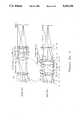
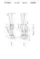
- FIGS. 1 through 7are schematic side views of zoom projection lens systems constructed in accordance with the invention.
- the upper portion of each of these figuresshows the zoom projection lens system in its short effective focal length (EFL) configuration while the lower portion shows it in its long EFL configuration.
- EFLeffective focal length
- the locations of the operative stop, the physical stop, and the pseudo stopare shown in each of the figures.
- L7 in FIGS. 1 and 4 and L8 in FIGS. 2, 3, and 5are used to enclose the lens system. Each has two flat surfaces and thus no optical power.
- FIG. 8is a schematic diagram showing an overall projection system in which the zoom projection lens systems of the present invention can be used.
- the present inventionrelates to projection zoom lens systems having entrance pupils which remain at substantially a fixed location as the system zooms between its minimum magnification (m' min ) and its maximum magnification (m' max ).
- the lens systemincludes two lens units with the first unit (object side unit) having a positive power and the second unit (image side unit) a negative power. Movement of the first unit serves to change the magnification of the system between m' min and m' max .
- the range of magnificationm' min to m' max
- m' minbeing approximately equal to 1/m' max .
- the second (image side) unitprovides compensation for the change of focus position caused by movement of the first unit and defines the overall focal lengths of the system. Also, the second unit can be used independently for focusing at different image distances, e.g., different screen distances.
- additional lens unitscan be employed in the practice of the invention to allow for telecentric systems, efficient correction of extended focal length ranges, minimization of lens element size, and minimization of barrel length.
- the key to designing the zoom projection lens systems of the present inventionis specifying the location of the system's entrance pupil, but not specifying the location of its physical aperture stop.
- thisis preferably done through the use of a pseudo-aperture stop.
- the aperture stop called for by the programis placed in object space at the desired location of the zoom projection lens system's entrance pupil.
- the aperture stopis placed in image space.
- the computed path of the lightmust pass through all lens surfaces (i.e., it must be in object space or image space as opposed to lens space) so that the aperture stop will be its own conjugate, i.e., so that the entrance pupil and the aperture stop will coincide.
- This aperture stop which is placed in object or image spaceis the pseudo-aperture stop.
- the desired location for the entrance pupil and thus of the pseudo-aperture stopwill physically be within the space between the first and last lens surfaces, i.e., the physical location of the pseudo-aperture stop will be in lens space.
- negative spacings between the calculation surfaces used by the computer programare employed.
- a computed light pathis used wherein light passes through the pseudo-aperture stop, then goes backwards to the first lens surface (thus the negative spacing), and then passes through that surface and all the rest of the lens surfaces on its way to the screen.
- the lightgoes through the lens elements, then goes backwards from the last lens surface to the pseudo-aperture stop by means of a negative spacing, and then proceeds on to the screen.
- lens design computer programscan be employed in the practice of the invention, e.g., the program sold by Optical Research Associates, Pasadena, Calif., under the trademark CODE V. Non-commercially available systems, of course, can also be used.
- zoom projection lens systemsfollowing the principles of the invention are produced. Such production is performed using lens fabrication and assembly procedures well known in the art. The invention, of course, can also be practiced using fabrication and assembly procedures which may be developed in the future. General discussions of applicable manufacturing techniques can be found in, for example, The Handbook of Plastic Optics, 2nd edition, U.S. Precision Lens Inc., Cincinnati, Ohio, 1983, and Horne, Douglas F., Optical Production Technology, 2nd ed., Adam Hilger, Ltd., Bristol, 1983, the relevant portions of which are incorporated herein by reference.
- FIGS. 1-7 and Tables 1-7correspond to these examples.
- the glasses and plastics referred to in Tables 1-7are set forth in Table 8, where the glass names are the SCHOTT designations and the abbreviation "polysty” has been used for polystyrene. Equivalent glasses made by other manufacturers can be used in the practice of the invention.
- the aspheric coefficients set forth in the tablesare for use in the following equation: ##EQU1## where z is the surface sag at a distance y from the optical axis of the system, c is the curvature of the lens at the optical axis, and k is a conic constant.
- Table 9shows the location (Dist.) and diameter (Dia.) of the physical aperture stop (by surface number S), the operative aperture stop (by surface number S and distance (Dist.) towards the object from that surface), and the entrance pupil at the minimum (position 1) and maximum (position 2) system focal lengths for each of these examples.
- the entrance pupil and the physical aperture stopremain at a substantially fixed location during zooming, while the operative aperture stop moves as zooming takes place.
- Table 9also sets forth Q-values for the lens systems of Examples 1-7 where the Q-value is defined by:
- EFL maxis the maximum value of the system's effective focal length
- ⁇is the semi-angular coverage in degrees at the system's minimum effective focal length
- CAis the clear aperture of the lens element nearest the image
- f/nois the distance from the object to the system's entrance pupil divided by the diameter of the entrance pupil for entrance pupils located a finite distance from the object and f/no is one over two times the numerical aperture determined by the illumination means for entrance pupils located an infinite distance from the object
- Lis the number of lens elements in the system which have optical power or correct aberrations.
- This valuetakes into account the lens system's zoom range (a performance factor), the angular coverage (another performance factor), the relative aperture (a further performance factor), the lens elements' diameters (a cost factor), and the number of lens elements (another cost factor).
- the zoom projection lens systems of the inventionachieve Q-values above 1.0 and in many cases, above 1.5. These values indicate that the systems have a combination of relatively high performance and relatively low cost.
- This exampleillustrates a zoom projection lens system constructed in accordance with the invention having two lens units U1 and U2.
- the lens elements making up the two unitsremain at fixed locations relative to one another as the zooming takes place. That is, the zooming involves only relative movement between the two lens units.
- the first (object) lens unithas positive optical power and serves to form a virtual image of the object at magnifications of -1.4 (short focal length) to -0.7 (long focal length).
- the operative aperture stoplies within this unit at the short focal length position, and moves through this unit to a position coincident with the entrance pupil (and the pseudo-aperture stop) as the focal length increases to its maximum value.
- the first lens unitincludes a negative element which as shown in FIG. 1 is located between two positive lens elements. If color correction is not required, the first unit can be further simplified by elimination of the negative element. In such a case, depending upon the application, the remaining two positive lens elements can be combined to produce a first lens unit having only a single lens element.
- the second (image) lens unithas negative optical power and remains fixed between the two focal length extremes. It is used as a compensator for intermediate focal lengths and can also be used for a focus adjustment for various distances to the image.
- the lens system of this exampleis constructed of acrylic plastic, each element having at least one aspherical surface, and dense flint glass elements, each having only spherical surfaces.
- the systemhas an f-number of 6 and a total angular coverage of 52 degrees.
- the zoom projection lens system of this exampleis similar to that of Example 1 and has an f-number of 6.6 and a total angular coverage of 52 degrees.
- An additional acrylic lens elementis employed nearest the object.
- the operative aperture stop as defined abovevaries during zooming from the image side of the positive (first) unit to the object side as the focal length is increased.
- This exampleis similar to Examples 1 and 2 above, except that the positive (first) unit uses optical glass for a positive element in addition to the flint glass for the negative element.
- the positive (first) unituses optical glass for a positive element in addition to the flint glass for the negative element.
- To provide aberration correctiona weak single element of plastic having an aspherical surface is placed nearest the object.
- the operative aperture stopmoves in a similar manner to that of Examples 1 and 2.
- the f-number for this exampleis 4.7 and the total angular coverage is 52 degrees.
- the positive (first) unithas a three element, positive, negative, positive construction.
- the negative (second) unitis in inverted order from the preceding examples.
- the f-number for the systemis 4.7 and the total angular coverage is 52 degrees.
- Example 3This example is similar to Example 3 above, except that the total angular coverage is 64.5 degrees, rather than 52 degrees as in Example 3.
- Four aspherical plastic surfacesare used to correct aberrations, and the system achieves an f-number of 4.5.
- the zoom projection lens system of this exampleemploys three lens units, namely, a first (object end) positive zooming unit, a second negative zooming unit, and a third (image end) positive unit which remains fixed during zooming and focusing.
- the first unithas a reverse telephoto construction for light traveling form right to left in FIG. 6.
- the f-number for the systemis 4.5 and the total angular coverage is 35 degrees.
- the zoom projection lens system of this examplehas a distance entrance pupil.
- the unit nearest the objecthas positive power and remains fixed in location. Different lens configurations can be placed on the image side.
- the exampleshows a positive singlet followed by a negative doublet and another positive singlet, all three units moving for change of focal length.
- the location of the operative aperture stop as defined abovevaries between the two sides of the negative unit during zooming.
- the unit nearest the objectis fixed because any motion would cause it to be larger in diameter, or violate the space required between the lens system and the object. Because this unit has the largest elements, it is the most expensive to manufacture.
- By using interchangeable zooming unitsmore than one focal length range can be realized without having to duplicate the expensive unit nearest the object.
- the f-number for the embodiment of Table 7is 6.3 and the total angular coverage is 42 degrees.
Landscapes
- Physics & Mathematics (AREA)
- General Physics & Mathematics (AREA)
- Optics & Photonics (AREA)
- Lenses (AREA)
Abstract
Description
Q=(EFL.sub.max * θ)/(CA*f/no*L)
TABLE 1 __________________________________________________________________________LENS SYSTEM PRESCRIPTION SN RADIUS THICKNESS MATERIAL CLR. AP. LENS NO. __________________________________________________________________________1 ∞ 0.00000 99.64 2 147.7706 8.30000 ACRYLIC 91.14L1 3 47.9490 48.00000 74.50 4 -116.5760 5.00000 ACRYLIC 64.39L2 5 6789.2319 0.33552 64.26 6 254.8877 11.09166 SF10 64.93 L3 7 -726.3653 42.28466 65.19 8 104.6865 24.00000 ACRYLIC 65.05 L4 9 -132.2950 26.74812 62.46 10 -131.2653 8.60000 SF10 47.90 L5 11 135.7989 0.90000 47.53 12 251.3018 29.12239 ACRYLIC 47.36 L6 13 -60.0909 49.46231 57.28 14 ∞ 5.00000 K5 60.70L7 15 ∞ -100.00000 61.34 16 ∞ 274.98691 47.09 __________________________________________________________________________ASPHERICAL SURFACE DATA SN AD AE AF AG AH AI k __________________________________________________________________________2 3.4939E-07 -7.5779E-12 6.3058E-15 -7.5592E-18 3.2205E-21 -2.4317E-25 0.0 4 -4.0243E-07 2.6883E-10 9.3864E-14 -6.0836E-17 -6.1237E-20 -4.4125E-23 -1.0 5 -4.2811E-07 2.2767E-10 -1.8110E-14 -3.0029E-17 -4.1024E-20 -4.5638E-23 0.0 8 -3.8878E-07 - 7.3047E-11 -6.4535E-14 4.1473E-17 2.1631E-20 -3.9818E-23 0.0 12 -4.8791E-07 2.3260E-10 -3.1838E-13 1.5959E-16 6.3956E-19 -7.1293E-22 0.0 __________________________________________________________________________ZOOM SPACINGS ZP/SN 7 13 EFL __________________________________________________________________________1 105.3189 10.1850 96.6610 2 7.0000 108.5023 186.8710 3 42.2847 49.4623 139.9860 __________________________________________________________________________
TABLE 2 __________________________________________________________________________LENS SYSTEM PRESCRIPTION SN RADIUS THICKNESS MATERIAL CLR. AP. LENS NO. __________________________________________________________________________1 ∞ 0.69681 107.86 2 100.0000 8.30000 ACRYLIC 92.14L1 3 42.8438 28.57154 73.97 4 -110.0461 5.00000 ACRYLIC 74.03L2 5 629.1417 0.53389 73.61 6 82.9746 11.09166 SF56 73.71L3 7 154.6644 43.28071 70.95 8 143.5025 21.50000 ACRYLIC 63.52 L4 9 1314.5530 28.69805 61.48 10 -83.7371 8.60000 SF1 61.72 L5 11 277.7317 0.30000 68.77 12 142.3509 22.30458 ACRYLIC 71.62 L6 13 -65.7208 0.30000 74.28 14 722.7241 9.50000 ACRYLIC 76.20 L7 15 -149.5103 40.32444 77.00 16 ∞ 5.00000 K5 77.09 L8 17 ∞ -100.00000 77.15 18 ∞ 324.99100 75.35 __________________________________________________________________________ASPHERICAL SURFACE DATA SN AD AE AF AG AH AI k __________________________________________________________________________2 5.7724E-07 7.3907E-11 5.2397E-14 -2.2704E-17 1.0569E-21 3.2716E-24 0.0 4 -4.4325E-07 -2.7693E-10 2.5830E-13 -9.2185E-17 -4.4867E-20 1.7037E-23 -1.0 8 -3.8400E-07 -4.1832E-11 -3.9682E-14 -4.3311E-17 -1.2823E-20 2.5134E-23 0.0 14 -2.9190E-07 -3.9975E-11 -1.2051E-14 -5.6163E-18 5.8932E-21 -3.3636E-24 0.0 __________________________________________________________________________ZOOM SPACINGS ZP/SN 7 15 EFL __________________________________________________________________________1 106.6248 0.1786 96.6628 2 7.8222 98.9813 186.8890 3 43.2807 40.3244 139.9930 __________________________________________________________________________
TABLE 3 __________________________________________________________________________LENS SYSTEM PRESCRIPTION SN RADIUS THICKNESS MATERIAL CLR. AP. LENS NO. __________________________________________________________________________1 ∞ 0.11596 120.22 2 132.1436 8.30000 ACRYLIC 105.86L1 3 57.8077 49.07854 88.90 4 -83.7485 5.00000 ACRYLIC 84.41L2 5 772.3318 0.33552 92.36 6 206.9599 11.09166 SF10 95.76 L3 7 -924.9597 41.22838 96.36 8 95.0301 21.50000 ACRYLIC 99.97 L4 9 -248.3701 30.78008 99.28 10 -88.5629 8.60000 SF10 91.47 L5 11 338.0039 0.30000 100.69 12 212.3057 29.20260 SK18 103.52 L6 13 -83.6662 0.30000 104.87 14 3349.2141 9.50000 ACRYLIC 95.39 L7 15 -747.2829 39.07597 93.48 16 ∞ 5.00000 K5 89.64 L8 17 ∞ -100.00000 89.74 18 ∞ 274.99890 94.24 __________________________________________________________________________ASPHERICAL SURFACE DATA SN AD AE AF AG AH AI k __________________________________________________________________________2 2.9965E-07 2.8973E-11 1.3936E-14 -8.9923E-18 2.9474E-21 -1.1117E-25 0.0 4 -6.8870E-07 8.0410E-11 4.2015E-14 -4.7154E-17 -3.2149E-21 1.5225E-24 -1.0 5 -3.5344E-07 2.0136E-10 -3.6244E-14 -4.3459E-18 -3.7854E-21 1.2806E-24 0.0 8 -1.2643E-07 -9.5958E-12 -3.1636E-15 5.7683E-18 -3.2113E-21 2.2571E-25 0.0 14 -3.8316E-07 -3.6409E-11 -1.2259E-14 -1.4381E-18 2.2317E-21 -7.5346E-25 0.0 __________________________________________________________________________ZOOM SPACINGS ZP/SN 7 15 EFL __________________________________________________________________________1 102.3759 1.1197 96.6657 2 7.0000 96.4956 186.8980 3 41.2284 39.0760 139.9990 __________________________________________________________________________
TABLE 4 __________________________________________________________________________LENS SYSTEM PRESCRIPTION SN RADIUS THICKNESS MATERIAL CLR. AP. LENS NO. __________________________________________________________________________1 ∞ 1.00000 137.13 2 129.7490 14.50000 POLYSTY 121.45 L1 3 1639.0670 0.15436 118.96 4 -657.8899 5.00000 ACRYLIC 118.90 L2 5 60.8125 61.11412 91.83 6 -54.2323 8.30000 ACRYLIC 81.34 L3 7 -79.2724 40.93186 88.71 8 88.6338 22.36147 ACRYLIC 96.50 L4 9 -165.1153 18.59682 96.36 10 -98.9888 9.00000 POLYSTY 90.95 L5 11 138.3304 8.11547 98.00 12 146.5779 24.77029 ACRYLIC 100.49 L6 13 -73.4081 41.24356 100.85 14 ∞ 5.00000 K5 98.04 L7 15 ∞ -100.00000 97.72 16 ∞ 275.00021 113.81 __________________________________________________________________________ASPHERICAL SURFACE DATA SN AD AE AF AG AH AI k __________________________________________________________________________2 8.3552E-08 -5.7211E-12 -4.7404E-16 6.1784E-19 5.4553E-23 -4.9177E-26 -1.0 3 5.9179E-08 2.9478E-11 2.3708E-15 -3.2984E-19 -9.8003E-23 -7.0219E-29 -12.0 4 3.5589E-07 1.6670E-11 1.0435E-15 3.1050E-19 -5.7773E-23 4.2700E-26 0.0 7 -1.9572E-07 -6.8472E-11 9.8730E-18 -7.6654E-18 -1.8888E-21 1.1968E-24 0.0 8 -2.0992E-07 -3.5773E-11 -1.6740E-14 3.0802E-20 1.0427E-21 -2.0784E-25 0.0 11 1.9869E-08 -1.2166E-10 -3.7602E-14 -7.4682E-18 -7.1816E-22 3.3144E-25 -1.0 12 -2.8050E-07 -1.8610E-11 -6.1007E-15 -3.0983E-18 -5.5898E-22 6.5688E-26 0.0 13 -7.2624E-08 1.6029E-11 7.8577E-15 3.8900E-18 1.4224E-21 4.1318E-25 -1.0 __________________________________________________________________________ZOOM SPACINGS ZP/SN 7 13 EFL __________________________________________________________________________1 93.7356 4.3519 99.9999 2 1.3292 96.7583 200.0000 3 40.9319 41.2436 140.0000 __________________________________________________________________________
TABLE 5 __________________________________________________________________________LENS SYSTEM PRESCRIPTION SN RADIUS THICKNESS MATERIAL CLR. AP. LENS NO. __________________________________________________________________________1 ∞ 35.00000 290.22 2 291.6506 14.69100 ACRYLIC 210.61L1 3 91.5528 85.10000 162.98 4 -252.9235 8.85000 ACRYLIC 149.60L2 5 1880.2089 0.20000 146.23 6 201.3033 12.00000 SF56 143.92L3 7 394.1693 73.25182 141.68 8 195.0503 19.00000 ACRYLIC 121.39 L4 9 -535.0200 72.85547 119.42 10 -123.0726 12.00000 SF5 104.56 L5 11 386.4710 0.46806 114.13 12 359.6228 28.00000 K5 115.37 L6 13 -155.1373 0.43917 122.36 14 -653.2521 21.75465 ACRYLIC 127.13 L7 15 -127.7701 83.85342 130.90 16 ∞ 1.50000 K5 143.13 L8 17 ∞ -145.00000 143.34 18 ∞ 499.76880 112.81 __________________________________________________________________________ASPHERICAL SURFACE DATA SN AD AE AF AG AH AI k __________________________________________________________________________2 6.8242E-08 -1.3550E-13 2.6193E-17 3.6012E-21 4.3287E-26 -1.9037E-29 0.0 4 -2.7254E-08 7.8741E-13 4.8712E-16 -1.9468E-20 -6.6543E-24 1.2531E-27 0.0 -2.2833E-08 -2.0492E-12 2.9533E-16 1.0220E-19 -7.2719E-23 9.9432E-27 0.0 14 -6.6254E-08 -3.7817E-13 8.2025E-17 -3.4893E-20 -1.2778E-23 3.0670E-27 0.0 __________________________________________________________________________ZOOM SPACINGS ZP/SN 7 15 EFL __________________________________________________________________________1 187.5544 2.3927 172.2890 2 9.0000 175.5812 331.5340 3 73.2518 83.8534 248.7870 __________________________________________________________________________
TABLE 6 __________________________________________________________________________LENS SYSTEM PRESCRIPTION SN RADIUS THICKNESS MATERIAL CLR. AP. LENS NO. __________________________________________________________________________1 ∞ 15.00000 193.23 2 1284.4359 14.00000 LF5 181.81L1 3 169.8491 24.41682 167.34 4 212.1903 34.00000 BK7 172.98 L2 5 -286.4625 64.47748 172.75 6 -208.7216 9.00000 ACRYLIC 160.22L3 7 669.6813 0.20000 155.91 8 439.5682 11.00000 ACRYLIC 156.69 L4 9 125.8011 6.58892 156.70 10 144.1627 14.00000 SF14 161.09 L5 11 260.0031 0.20000 160.83 12 153.0303 24.00000 ACRYLIC 164.18L6 13 903.3169 0.20000 163.64 14 218.9853 25.89357 BK7 159.07 L7 15 -342.6197 3.08925 158.24 16 -260.5514 14.00000 SF6 158.17 L8 17 -2867.9861 88.59519 152.24 18 -371.4034 15.00000 ACRYLIC 119.10 L9 19 -1102.9470 -0.66122 122.36 20 ∞ 489.98550 109.65 __________________________________________________________________________ASPHERICAL SURFACE DATA SN AD AE AF AG AH AI k __________________________________________________________________________7 -3.4433E-08 -1.7950E-12 3.6124E-16 -1.1122E-19 1.3025E-23 -5.2557E-28 0.0 13 -1.5099E-08 -1.5738E-12 - 1.0528E-16 -5.2941E-25 -3.1255e-25 -1.6262E-29 0.0 18 -1.3605E-07 -9.4245E-12 7.0024E-16 -3.0411E-19 2.0568E-23 -1.3422E-27 0.0 __________________________________________________________________________ZOOM SPACINGS ZP/SN 5 11 19 EFL __________________________________________________________________________1 8.5645 204.7524 -149.3006 349.995 2 64.4775 0.2000 -0.6612 699.981 __________________________________________________________________________
TABLE 7 __________________________________________________________________________LENS SYSTEM PRESCRIPTION SN RADIUS THICKNESS MATERIAL CLR. AP. LENS NO. __________________________________________________________________________1 ∞ -27.48860 40.47 2 235.6873 9.50800 FK5 79.71 L1 3 -433.4475 87.81900 76.98 4 -810.5880 2.00000 SK18 73.46L2 5 63.9254 4.46990 SK6 66.39 L3 6 87.3030 0.71320 65.41 7 69.5601 6.29220 POLYSTY 61.56 L4 8 112.1866 30.00000 61.80 9 -42.0495 4.00000 SF6 66.03 L5 10 -261.2156 0.29500 85.83 11 -645.2294 27.14260 ACRYLIC 91.25 L6 12 -56.4311 0.19456 97.32 13 243.9553 59.21634 ACRYLIC 125.78 L7 14 -90.5093 240.15401 140.58 __________________________________________________________________________ASPHERICAL SURFACE DATA SN AD AE AF AG AH AI k __________________________________________________________________________8 -5.0583E-07 2.9906E-10 -1.7018E-13 -1.8850E-16 -3.9000E-20 1.6430E-22 0.0 11 9.5975E-09 -1.0386E-11 -5.2100E-15 -1.0665E-18 4.1320E-22 6.1200E-25 0.0 12 2.3299E-07 8.3416E-11 3.2125E-15 4.2519E-18 2.3713E-21 8.5905E-25 0.0 13 -2.5822E-07 -9.1341E-12 -9.2901E-16 2.8111E-19 2.3000E-22 -5.5377E-26 0.0 __________________________________________________________________________ ZOOM SPACINGS ZP/SN 1 3 6 8 EFL __________________________________________________________________________1 -80.9854 2.2378 113.9058 54.5465 127.001 2 -27.4886 87.8190 0.7132 30.0000 254.985 __________________________________________________________________________
TABLE 8 ______________________________________ MATERIAL N.sub.e V.sub.e ______________________________________ 1 POLYSTY 1.594948 30.7 2 ACRYLIC 1.493538 57.3 3 SF10 1.734298 28.2 4 K5 1.524582 59.2 5 SF56 1.791794 25.9 6 SF1 1.723102 29.3 7 SF10 1.734298 28.2 8 SK18 1.641284 55.2 9 SF14 1.768587 26.3 10 LF5 1.584815 40.6 11 BK7 1.518720 64.0 12 SF6 1.812647 25.2 13 FK5 1.489142 70.2 ______________________________________
TABLE 9 ______________________________________ Physical Operative Entrance Ex. Stop Stop Pupil No. Q Pos. S Dia. S Dist. Dia. Dist. Dia. ______________________________________ 1 1.5 1 12 47.4 8 13.4 35.0 275 46 2 12 47.4 13 11.8 46.0 275 46 2 1.2 1 15 77.0 9 1.4 29.3 325 50 2 15 77.0 15 2.3 49.4 325 50 3 1.4 1 9 99.3 8 16.8 41.9 275 58 2 9 99.3 14 9.2 58.9 275 58 4 1.5 1 9 96.4 8 5.8 41.8 275 58 2 9 96.4 13 .0 58.9 275 58 5 1.6 1 8 121.4 9 24.3 77.6 500 112 2 8 121.4 15 31.5 111.9 500 112 6 1.7 1 13 164.6 11 180.6 114.0 490 110 2 13 164.6 18 14.0 109.8 490 110 7 1.5 1 8 61.8 6 85.1 26.2 infinite 2 8 61.8 3 19.2 37.5 infinite ______________________________________
Claims (36)
Q=(EFL.sub.max *θ)/(CA*f/no*L)
Priority Applications (5)
| Application Number | Priority Date | Filing Date | Title |
|---|---|---|---|
| US07/938,381US5313330A (en) | 1992-08-31 | 1992-08-31 | Zoom projection lens systems |
| DE69328891TDE69328891T2 (en) | 1992-08-31 | 1993-08-06 | Systems for projection zoom lenses |
| EP93112639AEP0585651B1 (en) | 1992-08-31 | 1993-08-06 | Zoom projection lens systems |
| EP99122218AEP0974859A3 (en) | 1992-08-31 | 1993-08-06 | Zoom projection lens systems |
| JP21539993AJP3513514B2 (en) | 1992-08-31 | 1993-08-31 | Zoom projection lens and manufacturing method thereof |
Applications Claiming Priority (1)
| Application Number | Priority Date | Filing Date | Title |
|---|---|---|---|
| US07/938,381US5313330A (en) | 1992-08-31 | 1992-08-31 | Zoom projection lens systems |
Publications (1)
| Publication Number | Publication Date |
|---|---|
| US5313330Atrue US5313330A (en) | 1994-05-17 |
Family
ID=25471335
Family Applications (1)
| Application Number | Title | Priority Date | Filing Date |
|---|---|---|---|
| US07/938,381Expired - LifetimeUS5313330A (en) | 1992-08-31 | 1992-08-31 | Zoom projection lens systems |
Country Status (4)
| Country | Link |
|---|---|
| US (1) | US5313330A (en) |
| EP (2) | EP0974859A3 (en) |
| JP (1) | JP3513514B2 (en) |
| DE (1) | DE69328891T2 (en) |
Cited By (77)
| Publication number | Priority date | Publication date | Assignee | Title |
|---|---|---|---|---|
| US5625495A (en)* | 1994-12-07 | 1997-04-29 | U.S. Precision Lens Inc. | Telecentric lens systems for forming an image of an object composed of pixels |
| EP0825474A3 (en)* | 1996-08-16 | 1998-10-28 | U.S. Precision Lens Inc. | Mini-zoom projection lenses for use with pixelized panels |
| US5841587A (en)* | 1996-04-29 | 1998-11-24 | U.S. Precision Lens Inc. | LCD projection lens |
| US5870228A (en)* | 1996-05-24 | 1999-02-09 | U.S. Precision Lens Inc. | Projection lenses having larger back focal length to focal length ratios |
| WO1999008138A1 (en)* | 1997-08-05 | 1999-02-18 | U.S. Precision Lens Incorporated | Zoom projection lens having a lens correction unit |
| US5900987A (en)* | 1997-02-13 | 1999-05-04 | U.S. Precision Lens Inc | Zoom projection lenses for use with pixelized panels |
| US5963375A (en)* | 1996-01-31 | 1999-10-05 | U.S. Precision Lens Inc. | Athermal LCD projection lens |
| US5969874A (en)* | 1996-05-30 | 1999-10-19 | U.S. Precision Lens Incorporated | Long focal length projection lenses |
| US5991089A (en)* | 1997-01-31 | 1999-11-23 | U.S. Precision Lens Inc. | Long focal length projection lenses for use with large pixelized panels |
| US6169636B1 (en) | 1999-05-04 | 2001-01-02 | U.S. Precision Lens Incorporated | Focus corrector for zoom projection lenses used with pixelized panels |
| US6301057B1 (en) | 1999-02-02 | 2001-10-09 | Corning Precision Lens | Long focal length projection lenses |
| US6304388B1 (en) | 1999-06-01 | 2001-10-16 | Minolta Co., Ltd. | Zoom lens system |
| US6324014B1 (en) | 1997-11-13 | 2001-11-27 | Corning Precision Lens | Wide field of view projection lenses for compact projection lens systems employing pixelized panels |
| US6476974B1 (en) | 2001-02-28 | 2002-11-05 | Corning Precision Lens Incorporated | Projection lenses for use with reflective pixelized panels |
| US20020191169A1 (en)* | 2001-03-28 | 2002-12-19 | Ryoko Otomo | Projection optical system and projection and light exposure apparatus using it |
| US20040261517A1 (en)* | 2003-04-10 | 2004-12-30 | Juergen Koehler | Arrangement of optical elements in projection systems |
| US20050083588A1 (en)* | 2003-07-01 | 2005-04-21 | Samsung Electronics Co., Ltd. | Projection optical system, projection television, and method of manufacturing lens included in projection optical system |
| US20060028739A1 (en)* | 2004-08-04 | 2006-02-09 | 3M Innovative Properties Company | Projection lenses having color-correcting rear lens units |
| US20060028741A1 (en)* | 2004-08-04 | 2006-02-09 | 3M Innovative Properties Company | Projection lenses having color-correcting rear lens units |
| US7145729B2 (en) | 2004-08-04 | 2006-12-05 | 3M Innovative Properties Company | Foldable projection lenses |
| US7161741B1 (en)* | 1999-07-17 | 2007-01-09 | Schaack David F | Focusing systems for perspective dimensional measurements and optical metrology |
| US20110007401A1 (en)* | 2009-07-09 | 2011-01-13 | Masaru Amano | Projection variable focus lens and projection display device |
| US20110007402A1 (en)* | 2009-07-09 | 2011-01-13 | Masaru Amano | Projection variable focus lens and projection display device |
| US20120044388A1 (en)* | 2010-08-20 | 2012-02-23 | Canon Kabushiki Kaisha | Lens apparatus and image pickup apparatus |
| TWI467311B (en)* | 2012-09-26 | 2015-01-01 | Qisda Corp | Projection apparatus |
| US9128264B2 (en) | 2013-08-09 | 2015-09-08 | Largan Precision Co., Ltd. | Image capturing lens assembly and image capturing device |
| US10089516B2 (en) | 2013-07-31 | 2018-10-02 | Digilens, Inc. | Method and apparatus for contact image sensing |
| US10145533B2 (en) | 2005-11-11 | 2018-12-04 | Digilens, Inc. | Compact holographic illumination device |
| US10156681B2 (en) | 2015-02-12 | 2018-12-18 | Digilens Inc. | Waveguide grating device |
| US10185154B2 (en) | 2011-04-07 | 2019-01-22 | Digilens, Inc. | Laser despeckler based on angular diversity |
| US10209517B2 (en) | 2013-05-20 | 2019-02-19 | Digilens, Inc. | Holographic waveguide eye tracker |
| US10216061B2 (en) | 2012-01-06 | 2019-02-26 | Digilens, Inc. | Contact image sensor using switchable bragg gratings |
| US10234696B2 (en) | 2007-07-26 | 2019-03-19 | Digilens, Inc. | Optical apparatus for recording a holographic device and method of recording |
| US10241330B2 (en) | 2014-09-19 | 2019-03-26 | Digilens, Inc. | Method and apparatus for generating input images for holographic waveguide displays |
| US10330777B2 (en) | 2015-01-20 | 2019-06-25 | Digilens Inc. | Holographic waveguide lidar |
| US10359736B2 (en) | 2014-08-08 | 2019-07-23 | Digilens Inc. | Method for holographic mastering and replication |
| US10409144B2 (en) | 2009-10-09 | 2019-09-10 | Digilens Inc. | Diffractive waveguide providing structured illumination for object detection |
| US10423222B2 (en) | 2014-09-26 | 2019-09-24 | Digilens Inc. | Holographic waveguide optical tracker |
| US10437051B2 (en) | 2012-05-11 | 2019-10-08 | Digilens Inc. | Apparatus for eye tracking |
| US10437064B2 (en) | 2015-01-12 | 2019-10-08 | Digilens Inc. | Environmentally isolated waveguide display |
| US10459145B2 (en) | 2015-03-16 | 2019-10-29 | Digilens Inc. | Waveguide device incorporating a light pipe |
| US10539760B2 (en) | 2017-08-30 | 2020-01-21 | Largan Precision Co., Ltd. | Imaging lens system, image capturing unit and electronic device |
| US10545346B2 (en) | 2017-01-05 | 2020-01-28 | Digilens Inc. | Wearable heads up displays |
| US10591756B2 (en) | 2015-03-31 | 2020-03-17 | Digilens Inc. | Method and apparatus for contact image sensing |
| US10642058B2 (en) | 2011-08-24 | 2020-05-05 | Digilens Inc. | Wearable data display |
| US10670876B2 (en) | 2011-08-24 | 2020-06-02 | Digilens Inc. | Waveguide laser illuminator incorporating a despeckler |
| US10678053B2 (en) | 2009-04-27 | 2020-06-09 | Digilens Inc. | Diffractive projection apparatus |
| US10690851B2 (en) | 2018-03-16 | 2020-06-23 | Digilens Inc. | Holographic waveguides incorporating birefringence control and methods for their fabrication |
| US10690916B2 (en) | 2015-10-05 | 2020-06-23 | Digilens Inc. | Apparatus for providing waveguide displays with two-dimensional pupil expansion |
| US10732569B2 (en) | 2018-01-08 | 2020-08-04 | Digilens Inc. | Systems and methods for high-throughput recording of holographic gratings in waveguide cells |
| US10859768B2 (en) | 2016-03-24 | 2020-12-08 | Digilens Inc. | Method and apparatus for providing a polarization selective holographic waveguide device |
| US10890707B2 (en) | 2016-04-11 | 2021-01-12 | Digilens Inc. | Holographic waveguide apparatus for structured light projection |
| US10914950B2 (en) | 2018-01-08 | 2021-02-09 | Digilens Inc. | Waveguide architectures and related methods of manufacturing |
| US10942430B2 (en) | 2017-10-16 | 2021-03-09 | Digilens Inc. | Systems and methods for multiplying the image resolution of a pixelated display |
| US10983340B2 (en) | 2016-02-04 | 2021-04-20 | Digilens Inc. | Holographic waveguide optical tracker |
| US11204540B2 (en) | 2009-10-09 | 2021-12-21 | Digilens Inc. | Diffractive waveguide providing a retinal image |
| US11307432B2 (en) | 2014-08-08 | 2022-04-19 | Digilens Inc. | Waveguide laser illuminator incorporating a Despeckler |
| US11378732B2 (en) | 2019-03-12 | 2022-07-05 | DigLens Inc. | Holographic waveguide backlight and related methods of manufacturing |
| US11402801B2 (en) | 2018-07-25 | 2022-08-02 | Digilens Inc. | Systems and methods for fabricating a multilayer optical structure |
| US11442222B2 (en) | 2019-08-29 | 2022-09-13 | Digilens Inc. | Evacuated gratings and methods of manufacturing |
| US11448937B2 (en) | 2012-11-16 | 2022-09-20 | Digilens Inc. | Transparent waveguide display for tiling a display having plural optical powers using overlapping and offset FOV tiles |
| US11460621B2 (en) | 2012-04-25 | 2022-10-04 | Rockwell Collins, Inc. | Holographic wide angle display |
| US11480788B2 (en) | 2015-01-12 | 2022-10-25 | Digilens Inc. | Light field displays incorporating holographic waveguides |
| US11513350B2 (en) | 2016-12-02 | 2022-11-29 | Digilens Inc. | Waveguide device with uniform output illumination |
| US11543594B2 (en) | 2019-02-15 | 2023-01-03 | Digilens Inc. | Methods and apparatuses for providing a holographic waveguide display using integrated gratings |
| US11681143B2 (en) | 2019-07-29 | 2023-06-20 | Digilens Inc. | Methods and apparatus for multiplying the image resolution and field-of-view of a pixelated display |
| US11726332B2 (en) | 2009-04-27 | 2023-08-15 | Digilens Inc. | Diffractive projection apparatus |
| US11747568B2 (en) | 2019-06-07 | 2023-09-05 | Digilens Inc. | Waveguides incorporating transmissive and reflective gratings and related methods of manufacturing |
| US12092914B2 (en) | 2018-01-08 | 2024-09-17 | Digilens Inc. | Systems and methods for manufacturing waveguide cells |
| US12140764B2 (en) | 2019-02-15 | 2024-11-12 | Digilens Inc. | Wide angle waveguide display |
| US12158612B2 (en) | 2021-03-05 | 2024-12-03 | Digilens Inc. | Evacuated periodic structures and methods of manufacturing |
| US12210153B2 (en) | 2019-01-14 | 2025-01-28 | Digilens Inc. | Holographic waveguide display with light control layer |
| US12222499B2 (en) | 2020-12-21 | 2025-02-11 | Digilens Inc. | Eye glow suppression in waveguide based displays |
| US12306585B2 (en) | 2018-01-08 | 2025-05-20 | Digilens Inc. | Methods for fabricating optical waveguides |
| US12360347B2 (en) | 2016-02-04 | 2025-07-15 | Largan Precision Co., Ltd. | Photographing optical lens assembly including seven lenses of +-++--+, +---+-+, +--+--+, +--++-+, +-+---+ OR +-+-+-- refractive powers, image capturing device and electronic device |
| US12397477B2 (en) | 2019-02-05 | 2025-08-26 | Digilens Inc. | Methods for compensating for optical surface nonuniformity |
| US12399326B2 (en) | 2021-01-07 | 2025-08-26 | Digilens Inc. | Grating structures for color waveguides |
Families Citing this family (13)
| Publication number | Priority date | Publication date | Assignee | Title |
|---|---|---|---|---|
| JP3435364B2 (en)* | 1998-12-24 | 2003-08-11 | ペンタックス株式会社 | Zoom lens system |
| GB9916715D0 (en)* | 1999-07-19 | 1999-09-15 | Secr Defence | Compound lens arrangement for use in lens arrays |
| EP1134606B1 (en) | 2000-01-18 | 2002-04-10 | Isco-Optic Gmbh | Projection lens |
| DE10244586B4 (en)* | 2002-09-20 | 2016-09-08 | Carl Zeiss Jena Gmbh | projection lens |
| US6765731B1 (en)* | 2003-03-28 | 2004-07-20 | 3M Innovative Properties Company | Low element count projection lenses for use with pixelized panels |
| JP2005106948A (en)* | 2003-09-29 | 2005-04-21 | Canon Inc | Projection optical system and image projection apparatus |
| TWI438475B (en)* | 2011-09-15 | 2014-05-21 | Largan Precision Co Ltd | Optical image capturing lens assembly |
| CN103163636B (en)* | 2011-12-09 | 2015-05-20 | 赛恩倍吉科技顾问(深圳)有限公司 | Zoom projection lens |
| CN108873279B (en)* | 2018-07-21 | 2020-12-22 | 福建福光股份有限公司 | Plastic aspheric zoom lens |
| CN109407275B (en)* | 2018-11-29 | 2024-01-16 | 福建福光股份有限公司 | Low-distortion light high-definition lens and imaging method thereof |
| CN110989143A (en)* | 2020-01-03 | 2020-04-10 | 杭州有人光电技术有限公司 | Virtual object lighting lens with object space telecentric |
| CN111474685B (en)* | 2020-06-01 | 2021-08-03 | 中国科学院长春光学精密机械与物理研究所 | A long focal length wide spectral band achromatic optical lens |
| CN112198639B (en)* | 2020-11-17 | 2025-09-16 | 浙江舜宇光学有限公司 | Optical imaging lens |
Citations (16)
| Publication number | Priority date | Publication date | Assignee | Title |
|---|---|---|---|---|
| US3920315A (en)* | 1974-10-15 | 1975-11-18 | Bell & Howell Co | Zoom projection lens |
| US4411488A (en)* | 1980-05-30 | 1983-10-25 | Barr & Stroud Limited | Afocal zoom refractor telescopes |
| US4623226A (en)* | 1981-12-08 | 1986-11-18 | Olympus Optical Co., Ltd. | Compact zoom lens system having three lens groups |
| US4632498A (en)* | 1982-11-23 | 1986-12-30 | Barr & Stroud Limited | Variable magnification infrared objective lens assembly |
| US4659171A (en)* | 1984-05-22 | 1987-04-21 | Barr & Stroud Limited | Infrared afocal refractor telescope |
| US4676581A (en)* | 1982-09-04 | 1987-06-30 | Pilkington P.E. Limited | Infra-red lenses |
| US4695119A (en)* | 1982-01-14 | 1987-09-22 | Barr & Stroud Limited | Infrared optical system |
| US4705363A (en)* | 1983-11-29 | 1987-11-10 | Canon Kabushiki Kaisha | Aberrational deterioration prevented zoom lens |
| US4708444A (en)* | 1983-03-01 | 1987-11-24 | Canon Kabushiki Kaisha | Photographic objective |
| US4749265A (en)* | 1983-07-14 | 1988-06-07 | Canon Kabushiki Kaisha | Zoom lens |
| US4838669A (en)* | 1987-03-17 | 1989-06-13 | Olympus Optical Co., Ltd. | Compact zoom lens system |
| JPH03293612A (en)* | 1990-04-12 | 1991-12-25 | Canon Inc | Zoom lens |
| JPH0483215A (en)* | 1990-07-25 | 1992-03-17 | Canon Inc | zoom lens |
| US5101299A (en)* | 1989-12-01 | 1992-03-31 | Minolta Camera Kabushiki Kaisha | Zoom lens system |
| US5114238A (en)* | 1990-06-28 | 1992-05-19 | Lockheed Missiles & Space Company, Inc. | Infrared catadioptric zoom relay telescope |
| JPH04172416A (en)* | 1990-11-06 | 1992-06-19 | Matsushita Electric Ind Co Ltd | Zoom lens and liquid crystal projector using it |
Family Cites Families (2)
| Publication number | Priority date | Publication date | Assignee | Title |
|---|---|---|---|---|
| US4909615A (en)* | 1987-05-29 | 1990-03-20 | Minolta Camera Kabushiki Kaisha | Zoom lens system for use in an image projecting apparatus with kohler illumination |
| JP2780309B2 (en)* | 1989-02-28 | 1998-07-30 | ミノルタ株式会社 | Compact zoom lens system |
- 1992
- 1992-08-31USUS07/938,381patent/US5313330A/ennot_activeExpired - Lifetime
- 1993
- 1993-08-06EPEP99122218Apatent/EP0974859A3/ennot_activeWithdrawn
- 1993-08-06EPEP93112639Apatent/EP0585651B1/ennot_activeExpired - Lifetime
- 1993-08-06DEDE69328891Tpatent/DE69328891T2/ennot_activeExpired - Fee Related
- 1993-08-31JPJP21539993Apatent/JP3513514B2/ennot_activeExpired - Fee Related
Patent Citations (16)
| Publication number | Priority date | Publication date | Assignee | Title |
|---|---|---|---|---|
| US3920315A (en)* | 1974-10-15 | 1975-11-18 | Bell & Howell Co | Zoom projection lens |
| US4411488A (en)* | 1980-05-30 | 1983-10-25 | Barr & Stroud Limited | Afocal zoom refractor telescopes |
| US4623226A (en)* | 1981-12-08 | 1986-11-18 | Olympus Optical Co., Ltd. | Compact zoom lens system having three lens groups |
| US4695119A (en)* | 1982-01-14 | 1987-09-22 | Barr & Stroud Limited | Infrared optical system |
| US4676581A (en)* | 1982-09-04 | 1987-06-30 | Pilkington P.E. Limited | Infra-red lenses |
| US4632498A (en)* | 1982-11-23 | 1986-12-30 | Barr & Stroud Limited | Variable magnification infrared objective lens assembly |
| US4708444A (en)* | 1983-03-01 | 1987-11-24 | Canon Kabushiki Kaisha | Photographic objective |
| US4749265A (en)* | 1983-07-14 | 1988-06-07 | Canon Kabushiki Kaisha | Zoom lens |
| US4705363A (en)* | 1983-11-29 | 1987-11-10 | Canon Kabushiki Kaisha | Aberrational deterioration prevented zoom lens |
| US4659171A (en)* | 1984-05-22 | 1987-04-21 | Barr & Stroud Limited | Infrared afocal refractor telescope |
| US4838669A (en)* | 1987-03-17 | 1989-06-13 | Olympus Optical Co., Ltd. | Compact zoom lens system |
| US5101299A (en)* | 1989-12-01 | 1992-03-31 | Minolta Camera Kabushiki Kaisha | Zoom lens system |
| JPH03293612A (en)* | 1990-04-12 | 1991-12-25 | Canon Inc | Zoom lens |
| US5114238A (en)* | 1990-06-28 | 1992-05-19 | Lockheed Missiles & Space Company, Inc. | Infrared catadioptric zoom relay telescope |
| JPH0483215A (en)* | 1990-07-25 | 1992-03-17 | Canon Inc | zoom lens |
| JPH04172416A (en)* | 1990-11-06 | 1992-06-19 | Matsushita Electric Ind Co Ltd | Zoom lens and liquid crystal projector using it |
Non-Patent Citations (3)
| Title |
|---|
| E. Betensky, "Zoom Lens Principles and Types", SPIE, vol. CR41, Warren J. Smith, Editor, pp. 88-116, 1992 (presented Jan. 1992). |
| E. Betensky, Zoom Lens Principles and Types , SPIE, vol. CR41, Warren J. Smith, Editor, pp. 88 116, 1992 (presented Jan. 1992).* |
| I. A. Neil, Use of Chalcogenide Glass in Thermal Infrared Telescopes, 1980 International Lens Design Conference (OSA), SPIE, vol. 237, p. 429.* |
Cited By (131)
| Publication number | Priority date | Publication date | Assignee | Title |
|---|---|---|---|---|
| USRE39424E1 (en)* | 1994-12-07 | 2006-12-12 | 3M Innovative Properties Company | Telecentric lens systems for forming an image of an object composed of pixels |
| US5625495A (en)* | 1994-12-07 | 1997-04-29 | U.S. Precision Lens Inc. | Telecentric lens systems for forming an image of an object composed of pixels |
| US5963375A (en)* | 1996-01-31 | 1999-10-05 | U.S. Precision Lens Inc. | Athermal LCD projection lens |
| US5841587A (en)* | 1996-04-29 | 1998-11-24 | U.S. Precision Lens Inc. | LCD projection lens |
| CN1098464C (en)* | 1996-05-24 | 2003-01-08 | 美国精密镜片股份有限公司 | Projection lenses having large back focal length to focal length ratios |
| US5870228A (en)* | 1996-05-24 | 1999-02-09 | U.S. Precision Lens Inc. | Projection lenses having larger back focal length to focal length ratios |
| US5969876A (en)* | 1996-05-24 | 1999-10-19 | U.S. Precision Lens Inc. | Projection lenses having large back focal length to focal length ratios |
| US5969874A (en)* | 1996-05-30 | 1999-10-19 | U.S. Precision Lens Incorporated | Long focal length projection lenses |
| CN1117992C (en)* | 1996-05-30 | 2003-08-13 | 美国精密镜片股份有限公司 | Long focal length projection lenses |
| US5900989A (en)* | 1996-08-16 | 1999-05-04 | U.S. Precision Lens Inc. | Mini-zoom projection lenses for use with pixelized panels |
| US6023375A (en)* | 1996-08-16 | 2000-02-08 | U.S. Precision Lens Inc. | Projection lenses for use with large pixelized panels |
| EP0825474A3 (en)* | 1996-08-16 | 1998-10-28 | U.S. Precision Lens Inc. | Mini-zoom projection lenses for use with pixelized panels |
| US5991089A (en)* | 1997-01-31 | 1999-11-23 | U.S. Precision Lens Inc. | Long focal length projection lenses for use with large pixelized panels |
| US5900987A (en)* | 1997-02-13 | 1999-05-04 | U.S. Precision Lens Inc | Zoom projection lenses for use with pixelized panels |
| WO1999008138A1 (en)* | 1997-08-05 | 1999-02-18 | U.S. Precision Lens Incorporated | Zoom projection lens having a lens correction unit |
| US6417971B1 (en)* | 1997-08-05 | 2002-07-09 | U.S. Precision Lens Incorporated | Zoom projection lens having a lens correction unit |
| USRE39911E1 (en)* | 1997-11-13 | 2007-11-06 | 3M Innovative Properties Company | Wide field of view projection lenses for compact projection lens systems employing pixelized panels |
| US6324014B1 (en) | 1997-11-13 | 2001-11-27 | Corning Precision Lens | Wide field of view projection lenses for compact projection lens systems employing pixelized panels |
| US6301057B1 (en) | 1999-02-02 | 2001-10-09 | Corning Precision Lens | Long focal length projection lenses |
| US6169636B1 (en) | 1999-05-04 | 2001-01-02 | U.S. Precision Lens Incorporated | Focus corrector for zoom projection lenses used with pixelized panels |
| EP1181610A4 (en)* | 1999-05-04 | 2003-05-21 | U S Prec Lens Inc | Projection lenses having reduced lateral color for use with pixelized panels |
| US6195209B1 (en) | 1999-05-04 | 2001-02-27 | U.S. Precision Lens Incorporated | Projection lenses having reduced lateral color for use with pixelized panels |
| US6304388B1 (en) | 1999-06-01 | 2001-10-16 | Minolta Co., Ltd. | Zoom lens system |
| US7161741B1 (en)* | 1999-07-17 | 2007-01-09 | Schaack David F | Focusing systems for perspective dimensional measurements and optical metrology |
| US6476974B1 (en) | 2001-02-28 | 2002-11-05 | Corning Precision Lens Incorporated | Projection lenses for use with reflective pixelized panels |
| US6903804B2 (en) | 2001-03-28 | 2005-06-07 | Fujinon Corporation | Projection optical system and projection and light exposure apparatus using it |
| US6816236B2 (en) | 2001-03-28 | 2004-11-09 | Fuji Photo Optical Co., Ltd. | Projection optical system and projection and light exposure apparatus using it |
| US20020191169A1 (en)* | 2001-03-28 | 2002-12-19 | Ryoko Otomo | Projection optical system and projection and light exposure apparatus using it |
| US20050002007A1 (en)* | 2001-03-28 | 2005-01-06 | Ryoko Otomo | Projection optical system and projection and light exposure apparatus using it |
| US6963456B2 (en) | 2003-04-10 | 2005-11-08 | Carl Zeiss Jena Gmbh | Arrangement of optical elements in projection systems |
| US20040261517A1 (en)* | 2003-04-10 | 2004-12-30 | Juergen Koehler | Arrangement of optical elements in projection systems |
| US20050083588A1 (en)* | 2003-07-01 | 2005-04-21 | Samsung Electronics Co., Ltd. | Projection optical system, projection television, and method of manufacturing lens included in projection optical system |
| US7324169B2 (en) | 2003-07-01 | 2008-01-29 | Samsung Electronics Co., Ltd. | Projection optical system, projection television, and method of manufacturing lens included in projection optical system |
| US20060028739A1 (en)* | 2004-08-04 | 2006-02-09 | 3M Innovative Properties Company | Projection lenses having color-correcting rear lens units |
| US20060028741A1 (en)* | 2004-08-04 | 2006-02-09 | 3M Innovative Properties Company | Projection lenses having color-correcting rear lens units |
| US7145729B2 (en) | 2004-08-04 | 2006-12-05 | 3M Innovative Properties Company | Foldable projection lenses |
| US7230770B2 (en) | 2004-08-04 | 2007-06-12 | 3M Innovative Properties Company | Projection lenses having color-correcting rear lens units |
| US10145533B2 (en) | 2005-11-11 | 2018-12-04 | Digilens, Inc. | Compact holographic illumination device |
| US10234696B2 (en) | 2007-07-26 | 2019-03-19 | Digilens, Inc. | Optical apparatus for recording a holographic device and method of recording |
| US10725312B2 (en) | 2007-07-26 | 2020-07-28 | Digilens Inc. | Laser illumination device |
| US11175512B2 (en) | 2009-04-27 | 2021-11-16 | Digilens Inc. | Diffractive projection apparatus |
| US11726332B2 (en) | 2009-04-27 | 2023-08-15 | Digilens Inc. | Diffractive projection apparatus |
| US10678053B2 (en) | 2009-04-27 | 2020-06-09 | Digilens Inc. | Diffractive projection apparatus |
| US8116010B2 (en) | 2009-07-09 | 2012-02-14 | Fujifilm Corporation | Projection variable focus lens and projection display device |
| US20110007402A1 (en)* | 2009-07-09 | 2011-01-13 | Masaru Amano | Projection variable focus lens and projection display device |
| US20110007401A1 (en)* | 2009-07-09 | 2011-01-13 | Masaru Amano | Projection variable focus lens and projection display device |
| US11204540B2 (en) | 2009-10-09 | 2021-12-21 | Digilens Inc. | Diffractive waveguide providing a retinal image |
| US10409144B2 (en) | 2009-10-09 | 2019-09-10 | Digilens Inc. | Diffractive waveguide providing structured illumination for object detection |
| US8421904B2 (en)* | 2010-08-20 | 2013-04-16 | Canon Kabushiki Kaisha | Lens apparatus and image pickup apparatus |
| US20120044388A1 (en)* | 2010-08-20 | 2012-02-23 | Canon Kabushiki Kaisha | Lens apparatus and image pickup apparatus |
| US11487131B2 (en) | 2011-04-07 | 2022-11-01 | Digilens Inc. | Laser despeckler based on angular diversity |
| US10185154B2 (en) | 2011-04-07 | 2019-01-22 | Digilens, Inc. | Laser despeckler based on angular diversity |
| US10642058B2 (en) | 2011-08-24 | 2020-05-05 | Digilens Inc. | Wearable data display |
| US12306418B2 (en) | 2011-08-24 | 2025-05-20 | Rockwell Collins, Inc. | Wearable data display |
| US11287666B2 (en) | 2011-08-24 | 2022-03-29 | Digilens, Inc. | Wearable data display |
| US10670876B2 (en) | 2011-08-24 | 2020-06-02 | Digilens Inc. | Waveguide laser illuminator incorporating a despeckler |
| US10216061B2 (en) | 2012-01-06 | 2019-02-26 | Digilens, Inc. | Contact image sensor using switchable bragg gratings |
| US10459311B2 (en) | 2012-01-06 | 2019-10-29 | Digilens Inc. | Contact image sensor using switchable Bragg gratings |
| US11460621B2 (en) | 2012-04-25 | 2022-10-04 | Rockwell Collins, Inc. | Holographic wide angle display |
| US11994674B2 (en) | 2012-05-11 | 2024-05-28 | Digilens Inc. | Apparatus for eye tracking |
| US10437051B2 (en) | 2012-05-11 | 2019-10-08 | Digilens Inc. | Apparatus for eye tracking |
| TWI467311B (en)* | 2012-09-26 | 2015-01-01 | Qisda Corp | Projection apparatus |
| US11448937B2 (en) | 2012-11-16 | 2022-09-20 | Digilens Inc. | Transparent waveguide display for tiling a display having plural optical powers using overlapping and offset FOV tiles |
| US12405507B2 (en) | 2012-11-16 | 2025-09-02 | Digilens Inc. | Transparent waveguide display with grating lamina that both couple and extract modulated light |
| US20230114549A1 (en)* | 2012-11-16 | 2023-04-13 | Rockwell Collins, Inc. | Transparent waveguide display |
| US11815781B2 (en)* | 2012-11-16 | 2023-11-14 | Rockwell Collins, Inc. | Transparent waveguide display |
| US11662590B2 (en) | 2013-05-20 | 2023-05-30 | Digilens Inc. | Holographic waveguide eye tracker |
| US10209517B2 (en) | 2013-05-20 | 2019-02-19 | Digilens, Inc. | Holographic waveguide eye tracker |
| US10089516B2 (en) | 2013-07-31 | 2018-10-02 | Digilens, Inc. | Method and apparatus for contact image sensing |
| US10423813B2 (en) | 2013-07-31 | 2019-09-24 | Digilens Inc. | Method and apparatus for contact image sensing |
| US9128264B2 (en) | 2013-08-09 | 2015-09-08 | Largan Precision Co., Ltd. | Image capturing lens assembly and image capturing device |
| US10359736B2 (en) | 2014-08-08 | 2019-07-23 | Digilens Inc. | Method for holographic mastering and replication |
| US11307432B2 (en) | 2014-08-08 | 2022-04-19 | Digilens Inc. | Waveguide laser illuminator incorporating a Despeckler |
| US11709373B2 (en) | 2014-08-08 | 2023-07-25 | Digilens Inc. | Waveguide laser illuminator incorporating a despeckler |
| US11726323B2 (en) | 2014-09-19 | 2023-08-15 | Digilens Inc. | Method and apparatus for generating input images for holographic waveguide displays |
| US10241330B2 (en) | 2014-09-19 | 2019-03-26 | Digilens, Inc. | Method and apparatus for generating input images for holographic waveguide displays |
| US10423222B2 (en) | 2014-09-26 | 2019-09-24 | Digilens Inc. | Holographic waveguide optical tracker |
| US10437064B2 (en) | 2015-01-12 | 2019-10-08 | Digilens Inc. | Environmentally isolated waveguide display |
| US11726329B2 (en) | 2015-01-12 | 2023-08-15 | Digilens Inc. | Environmentally isolated waveguide display |
| US11740472B2 (en) | 2015-01-12 | 2023-08-29 | Digilens Inc. | Environmentally isolated waveguide display |
| US11480788B2 (en) | 2015-01-12 | 2022-10-25 | Digilens Inc. | Light field displays incorporating holographic waveguides |
| US10330777B2 (en) | 2015-01-20 | 2019-06-25 | Digilens Inc. | Holographic waveguide lidar |
| US10527797B2 (en) | 2015-02-12 | 2020-01-07 | Digilens Inc. | Waveguide grating device |
| US11703645B2 (en) | 2015-02-12 | 2023-07-18 | Digilens Inc. | Waveguide grating device |
| US10156681B2 (en) | 2015-02-12 | 2018-12-18 | Digilens Inc. | Waveguide grating device |
| US12379547B2 (en) | 2015-02-12 | 2025-08-05 | Digilens Inc. | Waveguide grating device |
| US12013561B2 (en) | 2015-03-16 | 2024-06-18 | Digilens Inc. | Waveguide device incorporating a light pipe |
| US10459145B2 (en) | 2015-03-16 | 2019-10-29 | Digilens Inc. | Waveguide device incorporating a light pipe |
| US10591756B2 (en) | 2015-03-31 | 2020-03-17 | Digilens Inc. | Method and apparatus for contact image sensing |
| US10690916B2 (en) | 2015-10-05 | 2020-06-23 | Digilens Inc. | Apparatus for providing waveguide displays with two-dimensional pupil expansion |
| US11754842B2 (en) | 2015-10-05 | 2023-09-12 | Digilens Inc. | Apparatus for providing waveguide displays with two-dimensional pupil expansion |
| US12405471B2 (en) | 2015-10-05 | 2025-09-02 | Digilens Inc. | Apparatus for providing waveguide displays with two-dimensional pupil expansion |
| US11281013B2 (en) | 2015-10-05 | 2022-03-22 | Digilens Inc. | Apparatus for providing waveguide displays with two-dimensional pupil expansion |
| US10983340B2 (en) | 2016-02-04 | 2021-04-20 | Digilens Inc. | Holographic waveguide optical tracker |
| US12360347B2 (en) | 2016-02-04 | 2025-07-15 | Largan Precision Co., Ltd. | Photographing optical lens assembly including seven lenses of +-++--+, +---+-+, +--+--+, +--++-+, +-+---+ OR +-+-+-- refractive powers, image capturing device and electronic device |
| US10859768B2 (en) | 2016-03-24 | 2020-12-08 | Digilens Inc. | Method and apparatus for providing a polarization selective holographic waveguide device |
| US11604314B2 (en) | 2016-03-24 | 2023-03-14 | Digilens Inc. | Method and apparatus for providing a polarization selective holographic waveguide device |
| US10890707B2 (en) | 2016-04-11 | 2021-01-12 | Digilens Inc. | Holographic waveguide apparatus for structured light projection |
| US11513350B2 (en) | 2016-12-02 | 2022-11-29 | Digilens Inc. | Waveguide device with uniform output illumination |
| US12298513B2 (en) | 2016-12-02 | 2025-05-13 | Digilens Inc. | Waveguide device with uniform output illumination |
| US12248150B2 (en) | 2017-01-05 | 2025-03-11 | Digilens Inc. | Wearable heads up displays |
| US11194162B2 (en) | 2017-01-05 | 2021-12-07 | Digilens Inc. | Wearable heads up displays |
| US11586046B2 (en) | 2017-01-05 | 2023-02-21 | Digilens Inc. | Wearable heads up displays |
| US10545346B2 (en) | 2017-01-05 | 2020-01-28 | Digilens Inc. | Wearable heads up displays |
| US10539760B2 (en) | 2017-08-30 | 2020-01-21 | Largan Precision Co., Ltd. | Imaging lens system, image capturing unit and electronic device |
| US10942430B2 (en) | 2017-10-16 | 2021-03-09 | Digilens Inc. | Systems and methods for multiplying the image resolution of a pixelated display |
| US11573483B2 (en) | 2017-10-16 | 2023-02-07 | Digilens Inc. | Systems and methods for multiplying the image resolution of a pixelated display |
| US12092914B2 (en) | 2018-01-08 | 2024-09-17 | Digilens Inc. | Systems and methods for manufacturing waveguide cells |
| US10914950B2 (en) | 2018-01-08 | 2021-02-09 | Digilens Inc. | Waveguide architectures and related methods of manufacturing |
| US12352960B2 (en) | 2018-01-08 | 2025-07-08 | Digilens Inc. | Waveguide architectures and related methods of manufacturing |
| US12366823B2 (en) | 2018-01-08 | 2025-07-22 | Digilens Inc. | Systems and methods for high-throughput recording of holographic gratings in waveguide cells |
| US10732569B2 (en) | 2018-01-08 | 2020-08-04 | Digilens Inc. | Systems and methods for high-throughput recording of holographic gratings in waveguide cells |
| US12306585B2 (en) | 2018-01-08 | 2025-05-20 | Digilens Inc. | Methods for fabricating optical waveguides |
| US11726261B2 (en) | 2018-03-16 | 2023-08-15 | Digilens Inc. | Holographic waveguides incorporating birefringence control and methods for their fabrication |
| US10690851B2 (en) | 2018-03-16 | 2020-06-23 | Digilens Inc. | Holographic waveguides incorporating birefringence control and methods for their fabrication |
| US11150408B2 (en) | 2018-03-16 | 2021-10-19 | Digilens Inc. | Holographic waveguides incorporating birefringence control and methods for their fabrication |
| US11402801B2 (en) | 2018-07-25 | 2022-08-02 | Digilens Inc. | Systems and methods for fabricating a multilayer optical structure |
| US12210153B2 (en) | 2019-01-14 | 2025-01-28 | Digilens Inc. | Holographic waveguide display with light control layer |
| US12397477B2 (en) | 2019-02-05 | 2025-08-26 | Digilens Inc. | Methods for compensating for optical surface nonuniformity |
| US12140764B2 (en) | 2019-02-15 | 2024-11-12 | Digilens Inc. | Wide angle waveguide display |
| US11543594B2 (en) | 2019-02-15 | 2023-01-03 | Digilens Inc. | Methods and apparatuses for providing a holographic waveguide display using integrated gratings |
| US11378732B2 (en) | 2019-03-12 | 2022-07-05 | DigLens Inc. | Holographic waveguide backlight and related methods of manufacturing |
| US12271035B2 (en) | 2019-06-07 | 2025-04-08 | Digilens Inc. | Waveguides incorporating transmissive and reflective gratings and related methods of manufacturing |
| US11747568B2 (en) | 2019-06-07 | 2023-09-05 | Digilens Inc. | Waveguides incorporating transmissive and reflective gratings and related methods of manufacturing |
| US11681143B2 (en) | 2019-07-29 | 2023-06-20 | Digilens Inc. | Methods and apparatus for multiplying the image resolution and field-of-view of a pixelated display |
| US11442222B2 (en) | 2019-08-29 | 2022-09-13 | Digilens Inc. | Evacuated gratings and methods of manufacturing |
| US11899238B2 (en) | 2019-08-29 | 2024-02-13 | Digilens Inc. | Evacuated gratings and methods of manufacturing |
| US11592614B2 (en) | 2019-08-29 | 2023-02-28 | Digilens Inc. | Evacuated gratings and methods of manufacturing |
| US12222499B2 (en) | 2020-12-21 | 2025-02-11 | Digilens Inc. | Eye glow suppression in waveguide based displays |
| US12399326B2 (en) | 2021-01-07 | 2025-08-26 | Digilens Inc. | Grating structures for color waveguides |
| US12158612B2 (en) | 2021-03-05 | 2024-12-03 | Digilens Inc. | Evacuated periodic structures and methods of manufacturing |
Also Published As
| Publication number | Publication date |
|---|---|
| EP0585651A2 (en) | 1994-03-09 |
| EP0585651A3 (en) | 1995-01-04 |
| JP3513514B2 (en) | 2004-03-31 |
| JPH06160714A (en) | 1994-06-07 |
| EP0974859A3 (en) | 2000-05-03 |
| DE69328891T2 (en) | 2000-10-26 |
| DE69328891D1 (en) | 2000-07-27 |
| EP0974859A2 (en) | 2000-01-26 |
| EP0585651B1 (en) | 2000-06-21 |
Similar Documents
| Publication | Publication Date | Title |
|---|---|---|
| US5313330A (en) | Zoom projection lens systems | |
| CN104508532B (en) | Zoom lens, optical instrument, and method for manufacturing zoom lens | |
| CN113341550B (en) | Zoom lens applied to projection | |
| JPH0876014A (en) | Zoom lens system | |
| US6844987B2 (en) | Zoom lens system for covering superwide-angle area | |
| JPH0634885A (en) | Zoom lens | |
| AU731885B2 (en) | High performance zoom lens system | |
| US5825556A (en) | Zoom lens | |
| JP2526923B2 (en) | Zoom lenses | |
| JPH03158817A (en) | Variable power lens | |
| US5627677A (en) | Rear conversion lens with vibration-reduction function | |
| US5502597A (en) | Wide-angle photographic lens system and a photographic camera | |
| JP2014206612A (en) | Projection lens and projection type display device | |
| JPH01191819A (en) | High variable power zoom lens | |
| JP2893119B2 (en) | Zoom lens | |
| US5760970A (en) | Zoom lens of high magnification | |
| JP2870098B2 (en) | Compact zoom lens system | |
| JP2750775B2 (en) | Compact zoom lens | |
| JPH0483214A (en) | Variable power lens | |
| US5162844A (en) | Image projection apparatus | |
| JP3326877B2 (en) | Albada finder | |
| JP3012354B2 (en) | Zoom finder | |
| JPH1096858A (en) | Zoom lens | |
| US4294521A (en) | Rear stop type zoom lens | |
| JP2526892B2 (en) | Zoom lens |
Legal Events
| Date | Code | Title | Description |
|---|---|---|---|
| AS | Assignment | Owner name:U.S. PRECISION LENS INCORPORATED, A CORP. OF OHIO, Free format text:ASSIGNMENT OF ASSIGNORS INTEREST.;ASSIGNOR:BETENSKY, ELLIS I.;REEL/FRAME:006245/0767 Effective date:19920831 | |
| STCF | Information on status: patent grant | Free format text:PATENTED CASE | |
| FPAY | Fee payment | Year of fee payment:4 | |
| FPAY | Fee payment | Year of fee payment:8 | |
| AS | Assignment | Owner name:3M INNOVATIVE PROPERTIES COMPANY, MINNESOTA Free format text:ASSIGNMENT OF ASSIGNORS INTEREST;ASSIGNOR:3M PRECISION OPTICS, INC.;REEL/FRAME:013429/0259 Effective date:20030212 Owner name:3M PRECISION OPTICS, INC., OHIO Free format text:CHANGE OF NAME;ASSIGNOR:CORNING PRECISION LENS, INC.;REEL/FRAME:013429/0359 Effective date:20021213 | |
| FEPP | Fee payment procedure | Free format text:PAYOR NUMBER ASSIGNED (ORIGINAL EVENT CODE: ASPN); ENTITY STATUS OF PATENT OWNER: LARGE ENTITY | |
| FPAY | Fee payment | Year of fee payment:12 | |
| AS | Assignment | Owner name:REGENTS OF THE UNIVERSITY OF MINNESOTA,MINNESOTA Free format text:DONATION AGREEMENT;ASSIGNOR:3M INNOVATIVE PROPERTIES COMPANY;REEL/FRAME:024342/0629 Effective date:20091223 |