US5313128A - Lead wire elimination for enclosed spindle motor - Google Patents
Lead wire elimination for enclosed spindle motorDownload PDFInfo
- Publication number
- US5313128A US5313128AUS08/012,897US1289793AUS5313128AUS 5313128 AUS5313128 AUS 5313128AUS 1289793 AUS1289793 AUS 1289793AUS 5313128 AUS5313128 AUS 5313128A
- Authority
- US
- United States
- Prior art keywords
- shaft
- sheath
- circuit
- winding
- circuitry
- Prior art date
- Legal status (The legal status is an assumption and is not a legal conclusion. Google has not performed a legal analysis and makes no representation as to the accuracy of the status listed.)
- Expired - Lifetime
Links
Images


Classifications
- H—ELECTRICITY
- H02—GENERATION; CONVERSION OR DISTRIBUTION OF ELECTRIC POWER
- H02K—DYNAMO-ELECTRIC MACHINES
- H02K3/00—Details of windings
- H02K3/46—Fastening of windings on the stator or rotor structure
- H02K3/50—Fastening of winding heads, equalising connectors, or connections thereto
- H—ELECTRICITY
- H02—GENERATION; CONVERSION OR DISTRIBUTION OF ELECTRIC POWER
- H02K—DYNAMO-ELECTRIC MACHINES
- H02K5/00—Casings; Enclosures; Supports
- H02K5/04—Casings or enclosures characterised by the shape, form or construction thereof
- H02K5/22—Auxiliary parts of casings not covered by groups H02K5/06-H02K5/20, e.g. shaped to form connection boxes or terminal boxes
- H02K5/225—Terminal boxes or connection arrangements
- H—ELECTRICITY
- H05—ELECTRIC TECHNIQUES NOT OTHERWISE PROVIDED FOR
- H05K—PRINTED CIRCUITS; CASINGS OR CONSTRUCTIONAL DETAILS OF ELECTRIC APPARATUS; MANUFACTURE OF ASSEMBLAGES OF ELECTRICAL COMPONENTS
- H05K1/00—Printed circuits
- H05K1/02—Details
- H05K1/11—Printed elements for providing electric connections to or between printed circuits
- H05K1/118—Printed elements for providing electric connections to or between printed circuits specially for flexible printed circuits, e.g. using folded portions
- H—ELECTRICITY
- H02—GENERATION; CONVERSION OR DISTRIBUTION OF ELECTRIC POWER
- H02K—DYNAMO-ELECTRIC MACHINES
- H02K2203/00—Specific aspects not provided for in the other groups of this subclass relating to the windings
- H02K2203/03—Machines characterised by the wiring boards, i.e. printed circuit boards or similar structures for connecting the winding terminations
- H—ELECTRICITY
- H02—GENERATION; CONVERSION OR DISTRIBUTION OF ELECTRIC POWER
- H02K—DYNAMO-ELECTRIC MACHINES
- H02K2211/00—Specific aspects not provided for in the other groups of this subclass relating to measuring or protective devices or electric components
- H02K2211/03—Machines characterised by circuit boards, e.g. pcb
- H—ELECTRICITY
- H05—ELECTRIC TECHNIQUES NOT OTHERWISE PROVIDED FOR
- H05K—PRINTED CIRCUITS; CASINGS OR CONSTRUCTIONAL DETAILS OF ELECTRIC APPARATUS; MANUFACTURE OF ASSEMBLAGES OF ELECTRICAL COMPONENTS
- H05K2201/00—Indexing scheme relating to printed circuits covered by H05K1/00
- H05K2201/05—Flexible printed circuits [FPCs]
- H05K2201/052—Branched
- H—ELECTRICITY
- H05—ELECTRIC TECHNIQUES NOT OTHERWISE PROVIDED FOR
- H05K—PRINTED CIRCUITS; CASINGS OR CONSTRUCTIONAL DETAILS OF ELECTRIC APPARATUS; MANUFACTURE OF ASSEMBLAGES OF ELECTRICAL COMPONENTS
- H05K2201/00—Indexing scheme relating to printed circuits covered by H05K1/00
- H05K2201/10—Details of components or other objects attached to or integrated in a printed circuit board
- H05K2201/10007—Types of components
- H05K2201/1009—Electromotor
- H—ELECTRICITY
- H05—ELECTRIC TECHNIQUES NOT OTHERWISE PROVIDED FOR
- H05K—PRINTED CIRCUITS; CASINGS OR CONSTRUCTIONAL DETAILS OF ELECTRIC APPARATUS; MANUFACTURE OF ASSEMBLAGES OF ELECTRICAL COMPONENTS
- H05K3/00—Apparatus or processes for manufacturing printed circuits
- H05K3/0058—Laminating printed circuit boards onto other substrates, e.g. metallic substrates
- H—ELECTRICITY
- H05—ELECTRIC TECHNIQUES NOT OTHERWISE PROVIDED FOR
- H05K—PRINTED CIRCUITS; CASINGS OR CONSTRUCTIONAL DETAILS OF ELECTRIC APPARATUS; MANUFACTURE OF ASSEMBLAGES OF ELECTRICAL COMPONENTS
- H05K3/00—Apparatus or processes for manufacturing printed circuits
- H05K3/30—Assembling printed circuits with electric components, e.g. with resistor
- H05K3/303—Surface mounted components, e.g. affixing before soldering, aligning means, spacing means
- H05K3/305—Affixing by adhesive
- H—ELECTRICITY
- H05—ELECTRIC TECHNIQUES NOT OTHERWISE PROVIDED FOR
- H05K—PRINTED CIRCUITS; CASINGS OR CONSTRUCTIONAL DETAILS OF ELECTRIC APPARATUS; MANUFACTURE OF ASSEMBLAGES OF ELECTRICAL COMPONENTS
- H05K3/00—Apparatus or processes for manufacturing printed circuits
- H05K3/30—Assembling printed circuits with electric components, e.g. with resistor
- H05K3/32—Assembling printed circuits with electric components, e.g. with resistor electrically connecting electric components or wires to printed circuits
- H05K3/34—Assembling printed circuits with electric components, e.g. with resistor electrically connecting electric components or wires to printed circuits by soldering
- H05K3/3447—Lead-in-hole components
- Y—GENERAL TAGGING OF NEW TECHNOLOGICAL DEVELOPMENTS; GENERAL TAGGING OF CROSS-SECTIONAL TECHNOLOGIES SPANNING OVER SEVERAL SECTIONS OF THE IPC; TECHNICAL SUBJECTS COVERED BY FORMER USPC CROSS-REFERENCE ART COLLECTIONS [XRACs] AND DIGESTS
- Y10—TECHNICAL SUBJECTS COVERED BY FORMER USPC
- Y10S—TECHNICAL SUBJECTS COVERED BY FORMER USPC CROSS-REFERENCE ART COLLECTIONS [XRACs] AND DIGESTS
- Y10S310/00—Electrical generator or motor structure
- Y10S310/06—Printed-circuit motors and components
Definitions
- the present inventionrelates generally to the fabrication of spindle motors used primarily in disc drives and, more particularly, to the use of a flexible printed circuit in the construction of an enclosed spindle motor.
- Disc drivesare a common means of providing secondary storage in computer systems.
- Disc drivesgenerally consist of a plurality of vertically aligned magnetic media discs that store data thereon. Over the surface of each disc, a read/write head provides access to the stored data. In a typical access, the head is positioned by a motor some radially distance from the center of the disc. The discs are caused to rotate underneath the head; thereby giving access to the entire circumference of the disc.
- spindle motorsgenerally consist of a stator assembly defined by a number of poles radiating perpendicularly out from a shaft. Conducting wire is wound around each pole to provide the necessary electromotive force to the motor when the correct current is applied. In a three phased, nine-pole spindle motor, three separate wires are wound around the stator poles--one wire for three poles of the stator.
- Spindle motorsmay be placed into two broad categories: enclosed or cantilever/hub type spindle motors.
- enclosed spindle motora separate housing covers the stator assembly and defines an opening for the shaft to rise out of the housing.
- cantilever/hub type motoris not totally enclosed. Instead, the stator assembly is partially exposed to view.
- Wiring a spindle motoris typically a two-step process: first, the coil wires are wound around the poles, leaving a start and finish end to each wire; the ends of which are usually soldered to lead wires. These lead wires are then routed away from the stator to be electrically mated to outside circuitry., Typically, the winding of the coil wire is an automated process. In a 9-pole, 3-phase spindle motor, one continuous length of wire is wrapped around three adjacent poles by a dedicated winding machine. This dedicated machine leaves the ends of the windings at various, predetermined angular displacements around the stator.
- lead wiresare manually soldering to the winding ends. Once soldered, the lead wires are manually routed out of the stator assembly to become electrically connected to outside circuitry. Outside circuitry typically controls the current flow through the windings to produce the proper phase relations.
- lead wiresare routed differs depending on whether the spindle motor is an enclosed or a cantilever/hub type motor. For a cantilever/hub type spindle motor, the task of routing is less difficult. Because the stator assembly is not fully enclosed, the lead wires may be routed from the various angular displacement after the automated winding process. As discussed further below, flexible printed circuit have been used to provide electrical connection between the lead wires and outside circuitry in cantilever/hub type motors.
- lead wire routingis more involved. Since the stator assembly is enclosed in a housing, the lead wires are typically brought together at one given angular position around the stator and lead up along the shaft through the opening of the housing. Once outside the housing, the lead wires are then soldered to outside circuitry.
- the manual routing of lead wires to a common angular positionadds some error to the control of the motor.
- the dedicated winding machineprovides a standard number of windings per pole, typically 30 such windings. Routing extra lead wires around stator creates a resistance imbalance because the length of the different lead wires varies. This resistance imbalance creates an imbalance in the phase relations for the motor; and hence, in the angular velocity of the motor. Ultimately, the storage density of the discs is decreased because variations in the angular velocity of the motor drive may overload the capacity of the head to read or write data.
- the present inventionis a flexible printed circuit that eliminates the need for lead wire routing.
- the flexible printed circuit of the present inventioncomprises a plurality of electrical paths surrounded by a sheath of pliable MYLAR (polyester film) plastic.
- One side of the plasticis an adhesive that holds the circuit in place after it is wrapped around the shaft of the motor.
- the mylar sheathopens to expose the ends of each electrical path. Small amounts of solder are pre-deposited at these exposed ends. A probe, suitably heated and applied to these ends, releases the solder to form a electrical and physical contact.
- the flexible printed circuitis T-shaped.
- the base of the Twraps around the shaft.
- the electrical pathshave openings at the base of the T and connect with winding ends.
- the circuitis designed so that the paths are proximate to the ends after the circuit is secured to the shaft. No manual routing of the winding ends is required. To electrically mate the windings to the circuit paths, it is sufficient to hold the winding ends to the path ends and apply the requisite amount of heat to the solder.
- the other portion of the T-shaped circuitnarrows to fit longitudinally along the shaft of the motor.
- the shafthas a slot on its side that defines a narrow pathway away from the stator when the motor is eventually enclosed.
- the top of the T-shapecomprises a contact pad for the electrical paths. At final assembly, this pad is folded over onto the surface of another flexible printed circuit and the pad is soldered by the application of a heating probe.
- FIG. 1shows an embodiment of the flexible printed circuit constructed in accordance with the principles of the present invention.
- FIG. 2shows a prior art embodiment of a flexible printed circuit that used on a cantilever hub-type motors.
- FIG. 3is a perspective view of the flexible printed circuit as it appears when affixed to the stator and shaft.
- FIG. 4is a cross-sectional view of an enclosed spindle motor employing the prior method of manually routed lead wires.
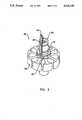
- FIG. 5is a cross-sectional view of a stator assembly employing the flexible printed circuit in accordance with the principles of the present invention.
- FIG. 6Ais a flat representation of the poles of the stator and their windings employing manually routed lead wires.
- FIG. 6Bis a flat representation of the poles of the stator and their windings employing the flexible printed circuit.
- FIG. 7is a cross-sectional view of a stator assembly with flexible printed circuit after the assembly is enclosed.
- FIG. 8is a cross-sectional view of the enclosed motor mated to an outside assembly having a separate flexible printed circuit.
- FIG. 9is an overhead view of the enclosed motor mated to an outside assembly having a separate flexible printed circuit.
- flexible printed circuit 100is depicted in accordance with the principles of the present invention.
- Circuit 100is shown with four electrical paths, each starting at contacts 120, 190, 200, and 210. These paths are sheathed in insulator 110.
- Insulator 110is made of a flexible mylar plastic in the presently preferred embodiment. It should be appreciated that any suitably flexible insulating material will suffice and the use of mylar plastic should not be construed as a limitation on the present invention.
- Circuit 100is essentially constructed in a T-shape. As discussed below, the T-shape facilities the final assembly of an enclosed spindle motor.
- One side of circuit 100has an adhesive coating (not shown) that allows circuit 100 to adhere to the shaft of the stator.
- the other side of circuit 100has openings in insulator 110 for contacts 120, 130, 140, 150, 160, 170, 180, 190, 200, and 210. These openings expose the conducting surface of the contacts to provide electrical and physical mating.
- a small amount of solder(not shown) is predeposited. As discussed below, predeposited solder eases the soldering process by reducing the amount of manual labor involved in construction of an enclosed spindle motor.
- circuit 100could be constructed with either more or less electrical pathways than the four pathways depicted and that the particular number of paths should not be construed as a limitation on the present invention. Additionally, the adhesive backing deposited on circuit 100 is one of many possible means of securing circuit 100 to the shaft of the stator and should not be construed as a limitation.
- FIG. 2shows flexible printed circuit 220 currently used on non-enclosed, cantilever hub motor 260.
- Circuit 220has pathway 240 that connects to motor 260 in a circular fashion surrounding shaft 250.
- Contact pad 230electrically connects motor 260 to outside circuitry.
- stator assembly housingwould have to have a separate opening to accommodate circuit 220.
- FIG. 3shows flexible printed circuit 100 attached to stator assembly 300 in accordance to the principles of the present invention.
- assembly 300comprises nine-pole stator 330 and shaft 310, running perpendicularly through stator 330.
- Shaft 310defines slot 320 which provides an pathway for circuit 100 when the assembly 300 is enclosed.
- Nine-pole stator 330supports three windings (not shown in FIG. 3). Each winding wire is wrapped around three separate poles. Normally, a dedicated machine automatically winds the wires around the poles. The ends of the windings are scattered at various angular positions about shaft 310. However, because the process is automated, the angular positions are constant, that is the ends are always located in the same position about shaft 310. As discussed below, the present invention takes advantage of this positional regularity.
- circuit 100is secured around shaft 310 by an adhesive backing (not shown) deposited on one side of its surface.
- the other side of circuit 100holds the contacts, such as contact 180.
- Insulator 110is opened at the contacts to provide electrical and physical coupling.
- Circuit 100is designed so that its contacts are always proximate to the winding ends whose positions are regularly provided by the automatic winding process. It will be appreciated that additional lead wire is not needed to form a pathway from the winding ends out of the housing of the enclosed motor.
- the ends of the windingsare physically placed on its designated contact point and a heat probe is applied to the point, thereby releasing its predeposited solder.
- Predeposited solderreduces the amount of manual labor required because a technician need not hold a separate strand of solder while holding winding end to the contact and applying a heat probe.
- FIG. 4is a cross-sectional view of stator 330 using lead wires 420 to electrically mate windings to outside circuitry, as practiced in the prior art.
- Lead wires 420are typically soldered individually to the winding ends and manually wrapped around shaft 310 to a common exit point up shaft 310. To hold individual lead wires 420 in place, clip 410 was wrapped around shaft 310; thus, pinching wires 420 to shaft 310.
- FIG. 5is a cross-sectional view of stator 330 using flexible printed circuit 100 made in accordance with the principles of the present invention. As noted above, there is no need in the present invention to manually route individual lead wires up along shaft 310. It will also be appreciated that the present invention obviates the need for clip 410 to hold circuit 100 in place.
- FIG. 6Ais a flat representation of the poles and their windings using manual lead wire routing.
- Three wires 620, 630, and 640are wound around poles 610.
- Each wirehas a start and a finish ending, depicted as S 1 , S 2 , S 3 , and F 1 , F 2 , F 3 respectively.
- the finish endingsare twisted and terminated at common point 650.
- the start endingsare manually routed up shaft 310.
- FIG. 6Ashows the need for variable lengths of wire to connect the different windings to the start endings S 1 , S 2 , and S 3 .
- wire 640traverses poles 2, 3, 4, 5 and 6. This traversal of poles adds to the overall length of wire 640.
- additional wireis needed for paths labelled 620 and 630 to traverse poles to arrive at the starting points. Because the separate lengths of additional wire are different for wires 620, 630, and 640, the total resistance along these wires are different. It is the difference in resistance along these wires that causes a phase imbalance in the currents along these wires. This imbalance is ultimately undesirable because it causes positioning error in the rotation of the storage discs. Consequently, the potential storage density on the storage discs is decreased.
- FIG. 6Bis a flat representation of poles and their windings as practiced in the presently preferred embodiment.
- Wires 620, 630, 640are identical to the wires depicted in FIG. 6A except that their endings are mated to circuit 00.
- FIG. 6Bshows that circuit 100 does away with the need for additional lead wire. It will be appreciated that the lengths of wires 620, 630, and 640 are identical and the phase imbalance due to variable resistance is avoided. Thus, circuit 100 allows for greater accuracy in the control of the spindle motor and a greater storage density per disc is consequently possible.
- finish endingsF 1 , F 2 , and F 3 , are electrically mated together since their contact points are located on the same electrical path. Start endings have their own separate electrical path that will be electrically connected to outside circuitry.
- FIG. 7is a cross-sectional view of stator 330 with circuit 100 after housing 710 encloses the stator. It will be noted that circuit 100 rides securely up shaft 310 to provide electrical connection to outside circuitry.
- FIG. 8is a cross-sectional view of spindle motor after bushing 810 is mated to the assembly in FIG. 7. Separate flexible printed circuit 820 surrounds bushing 810 and provides electrical connection to outside control circuitry. Flexible printed circuit 100 is shown as bent over and mated, both physically and electrically, to circuit 820. The contacts on the top of circuit 100 also contain predeposited solder and soldering is accomplished by applying a heat probe to the contacts. Plug 830 is used to reduce air flow from the interior of motor to the exterior.
- the prior artteaches the use of adhesive; elimination of adhesive is highly desirable to avoid contaimination of the HDA.
- FIG. 9is a top view of stator assembly as depicted in FIG. 8.
- FIG. 9shows in greater detail the manner in which circuit 100 is mated to circuit 820.
- the top of the T-shaped circuit 100is bent so as to make contact with corresponding electrical contact on circuit 820.
- circuit 820is made of the same mylar plastic that circuit 100 is made.
- Contacts 840are formed by openings in the mylar sheath of circuit 820. These contact, in turn, make physical and electrical connections with the requisite outside circuitry.
Landscapes
- Engineering & Computer Science (AREA)
- Power Engineering (AREA)
- Microelectronics & Electronic Packaging (AREA)
- Insulation, Fastening Of Motor, Generator Windings (AREA)
Abstract
Description
Claims (6)
Priority Applications (1)
| Application Number | Priority Date | Filing Date | Title |
|---|---|---|---|
| US08/012,897US5313128A (en) | 1993-02-03 | 1993-02-03 | Lead wire elimination for enclosed spindle motor |
Applications Claiming Priority (1)
| Application Number | Priority Date | Filing Date | Title |
|---|---|---|---|
| US08/012,897US5313128A (en) | 1993-02-03 | 1993-02-03 | Lead wire elimination for enclosed spindle motor |
Publications (1)
| Publication Number | Publication Date |
|---|---|
| US5313128Atrue US5313128A (en) | 1994-05-17 |
Family
ID=21757272
Family Applications (1)
| Application Number | Title | Priority Date | Filing Date |
|---|---|---|---|
| US08/012,897Expired - LifetimeUS5313128A (en) | 1993-02-03 | 1993-02-03 | Lead wire elimination for enclosed spindle motor |
Country Status (1)
| Country | Link |
|---|---|
| US (1) | US5313128A (en) |
Cited By (22)
| Publication number | Priority date | Publication date | Assignee | Title |
|---|---|---|---|---|
| US5493159A (en)* | 1994-07-19 | 1996-02-20 | Synektron Corporation | Flex circuit for electric motor |
| US5541787A (en)* | 1990-11-09 | 1996-07-30 | Seagate Technology, Inc. | Head disc assembly with printed circuit cable connector adapted for automated assembly |
| US6057616A (en)* | 1998-04-02 | 2000-05-02 | Seagate Technology, Inc. | Stator interconnect ring |
| US6121701A (en)* | 1997-06-02 | 2000-09-19 | Seagate Technology Llc | Snap on flexible printed circuit connector |
| US6300739B1 (en) | 1999-12-06 | 2001-10-09 | Hr Textron Inc. | Low cost limited angle torque DC brushless servomotor and method for fabricating thereof |
| US6497035B1 (en) | 1999-12-06 | 2002-12-24 | Hr Textron, Inc. | Hall position sensor |
| US6750575B2 (en) | 2001-08-21 | 2004-06-15 | General Electric Company | Method and apparatus for sensing the angular position of a rotating member |
| US20050057110A1 (en)* | 2003-09-15 | 2005-03-17 | Wolfe Melvin E. | Electric motor |
| US20050194851A1 (en)* | 2004-03-08 | 2005-09-08 | Siemens Aktiengesellschaft | Electric machine with a circuit board for wiring lines of a winding system |
| US20070046127A1 (en)* | 2005-08-23 | 2007-03-01 | Seagate Technology Llc | Motor assembly with an integrated flexible printed circuit |
| US9556873B2 (en) | 2013-02-27 | 2017-01-31 | Tc1 Llc | Startup sequence for centrifugal pump with levitated impeller |
| US9623161B2 (en) | 2014-08-26 | 2017-04-18 | Tc1 Llc | Blood pump and method of suction detection |
| US9638202B2 (en) | 2010-09-14 | 2017-05-02 | Tc1 Llc | Centrifugal pump apparatus |
| US9709061B2 (en) | 2013-01-24 | 2017-07-18 | Tc1 Llc | Impeller position compensation using field oriented control |
| US9850906B2 (en)* | 2011-03-28 | 2017-12-26 | Tc1 Llc | Rotation drive device and centrifugal pump apparatus employing same |
| US10052420B2 (en) | 2013-04-30 | 2018-08-21 | Tc1 Llc | Heart beat identification and pump speed synchronization |
| US10117983B2 (en) | 2015-11-16 | 2018-11-06 | Tc1 Llc | Pressure/flow characteristic modification of a centrifugal pump in a ventricular assist device |
| US10166318B2 (en) | 2015-02-12 | 2019-01-01 | Tc1 Llc | System and method for controlling the position of a levitated rotor |
| US10245361B2 (en) | 2015-02-13 | 2019-04-02 | Tc1 Llc | Impeller suspension mechanism for heart pump |
| US10371152B2 (en) | 2015-02-12 | 2019-08-06 | Tc1 Llc | Alternating pump gaps |
| US10506935B2 (en) | 2015-02-11 | 2019-12-17 | Tc1 Llc | Heart beat identification and pump speed synchronization |
| US11991825B2 (en)* | 2018-07-20 | 2024-05-21 | Beijing Boe Optoelectronics Technology Co., Ltd. | Flexible circuit board, light bar, light source and display device |
Citations (8)
| Publication number | Priority date | Publication date | Assignee | Title |
|---|---|---|---|---|
| US3270122A (en)* | 1962-04-18 | 1966-08-30 | Minnesota Mining & Mfg | Adherent conductor |
| US4661733A (en)* | 1985-04-03 | 1987-04-28 | Asgalium Sa | DC motor |
| US4724346A (en)* | 1985-09-23 | 1988-02-09 | Siemens Aktiengesellschaft | Permanent magnet-excited external rotor motor |
| US4870311A (en)* | 1988-10-11 | 1989-09-26 | Honeywell Inc. | Wireless slip ring assembly |
| US4931598A (en)* | 1988-12-30 | 1990-06-05 | 3M Company | Electrical connector tape |
| US5023734A (en)* | 1988-10-31 | 1991-06-11 | Victor Company Of Japan, Ltd. | Cylindrical rotary transducer |
| US5031061A (en)* | 1989-09-27 | 1991-07-09 | Quantum Corporation | Disk drive hub assembly |
| US5097366A (en)* | 1989-06-30 | 1992-03-17 | Victor Company Of Japan, Ltd. | Small-size magnetic disk drive mechanism with hermetically sealed chamber |
- 1993
- 1993-02-03USUS08/012,897patent/US5313128A/ennot_activeExpired - Lifetime
Patent Citations (8)
| Publication number | Priority date | Publication date | Assignee | Title |
|---|---|---|---|---|
| US3270122A (en)* | 1962-04-18 | 1966-08-30 | Minnesota Mining & Mfg | Adherent conductor |
| US4661733A (en)* | 1985-04-03 | 1987-04-28 | Asgalium Sa | DC motor |
| US4724346A (en)* | 1985-09-23 | 1988-02-09 | Siemens Aktiengesellschaft | Permanent magnet-excited external rotor motor |
| US4870311A (en)* | 1988-10-11 | 1989-09-26 | Honeywell Inc. | Wireless slip ring assembly |
| US5023734A (en)* | 1988-10-31 | 1991-06-11 | Victor Company Of Japan, Ltd. | Cylindrical rotary transducer |
| US4931598A (en)* | 1988-12-30 | 1990-06-05 | 3M Company | Electrical connector tape |
| US5097366A (en)* | 1989-06-30 | 1992-03-17 | Victor Company Of Japan, Ltd. | Small-size magnetic disk drive mechanism with hermetically sealed chamber |
| US5031061A (en)* | 1989-09-27 | 1991-07-09 | Quantum Corporation | Disk drive hub assembly |
Cited By (41)
| Publication number | Priority date | Publication date | Assignee | Title |
|---|---|---|---|---|
| US5541787A (en)* | 1990-11-09 | 1996-07-30 | Seagate Technology, Inc. | Head disc assembly with printed circuit cable connector adapted for automated assembly |
| US5493159A (en)* | 1994-07-19 | 1996-02-20 | Synektron Corporation | Flex circuit for electric motor |
| US6121701A (en)* | 1997-06-02 | 2000-09-19 | Seagate Technology Llc | Snap on flexible printed circuit connector |
| US6528914B2 (en)* | 1997-06-02 | 2003-03-04 | Seagate Technology Llc | Snap on flexible printed circuit connector |
| US6057616A (en)* | 1998-04-02 | 2000-05-02 | Seagate Technology, Inc. | Stator interconnect ring |
| US6614138B1 (en) | 1998-04-02 | 2003-09-02 | Seagate Technology Llc | Stator interconnect ring |
| US6300739B1 (en) | 1999-12-06 | 2001-10-09 | Hr Textron Inc. | Low cost limited angle torque DC brushless servomotor and method for fabricating thereof |
| US6497035B1 (en) | 1999-12-06 | 2002-12-24 | Hr Textron, Inc. | Hall position sensor |
| US6750575B2 (en) | 2001-08-21 | 2004-06-15 | General Electric Company | Method and apparatus for sensing the angular position of a rotating member |
| US20050057110A1 (en)* | 2003-09-15 | 2005-03-17 | Wolfe Melvin E. | Electric motor |
| US8141231B2 (en) | 2003-09-15 | 2012-03-27 | Shop Vac | Electric motor |
| US20050194851A1 (en)* | 2004-03-08 | 2005-09-08 | Siemens Aktiengesellschaft | Electric machine with a circuit board for wiring lines of a winding system |
| EP1578003A1 (en)* | 2004-03-08 | 2005-09-21 | Siemens Aktiengesellschaft | Electric machine with a device for connecting coil ends |
| US7202582B2 (en) | 2004-03-08 | 2007-04-10 | Siemens Aktiengesellschaft | Electric machine with a circuit board for wiring lines of a winding system |
| US20070046127A1 (en)* | 2005-08-23 | 2007-03-01 | Seagate Technology Llc | Motor assembly with an integrated flexible printed circuit |
| US7550890B2 (en) | 2005-08-23 | 2009-06-23 | Seagate Technology Llc | Motor assembly with an integrated flexible printed circuit |
| US20090229107A1 (en)* | 2005-08-23 | 2009-09-17 | Seagate Technology Llc | Motor Assembly with an Integrated Flexible Printed Circuit |
| US8046904B2 (en) | 2005-08-23 | 2011-11-01 | Seagate Technology | Motor assembly method with an integrated flexible printed circuit |
| US9638202B2 (en) | 2010-09-14 | 2017-05-02 | Tc1 Llc | Centrifugal pump apparatus |
| US9850906B2 (en)* | 2011-03-28 | 2017-12-26 | Tc1 Llc | Rotation drive device and centrifugal pump apparatus employing same |
| US9709061B2 (en) | 2013-01-24 | 2017-07-18 | Tc1 Llc | Impeller position compensation using field oriented control |
| US9556873B2 (en) | 2013-02-27 | 2017-01-31 | Tc1 Llc | Startup sequence for centrifugal pump with levitated impeller |
| US10052420B2 (en) | 2013-04-30 | 2018-08-21 | Tc1 Llc | Heart beat identification and pump speed synchronization |
| US9623161B2 (en) | 2014-08-26 | 2017-04-18 | Tc1 Llc | Blood pump and method of suction detection |
| US11712167B2 (en) | 2015-02-11 | 2023-08-01 | Tc1 Llc | Heart beat identification and pump speed synchronization |
| US12213766B2 (en) | 2015-02-11 | 2025-02-04 | Tc1 Llc | Heart beat identification and pump speed synchronization |
| US10506935B2 (en) | 2015-02-11 | 2019-12-17 | Tc1 Llc | Heart beat identification and pump speed synchronization |
| US10856748B2 (en) | 2015-02-11 | 2020-12-08 | Tc1 Llc | Heart beat identification and pump speed synchronization |
| US10371152B2 (en) | 2015-02-12 | 2019-08-06 | Tc1 Llc | Alternating pump gaps |
| US10874782B2 (en) | 2015-02-12 | 2020-12-29 | Tc1 Llc | System and method for controlling the position of a levitated rotor |
| US12297836B2 (en) | 2015-02-12 | 2025-05-13 | Tc1 Llc | Alternating pump gaps |
| US11015605B2 (en) | 2015-02-12 | 2021-05-25 | Tc1 Llc | Alternating pump gaps |
| US10166318B2 (en) | 2015-02-12 | 2019-01-01 | Tc1 Llc | System and method for controlling the position of a levitated rotor |
| US12285598B2 (en) | 2015-02-12 | 2025-04-29 | Tc1 Llc | System and method for controlling the position of a levitated rotor |
| US11724097B2 (en) | 2015-02-12 | 2023-08-15 | Tc1 Llc | System and method for controlling the position of a levitated rotor |
| US11781551B2 (en) | 2015-02-12 | 2023-10-10 | Tc1 Llc | Alternating pump gaps |
| US10245361B2 (en) | 2015-02-13 | 2019-04-02 | Tc1 Llc | Impeller suspension mechanism for heart pump |
| US11639722B2 (en) | 2015-11-16 | 2023-05-02 | Tc1 Llc | Pressure/flow characteristic modification of a centrifugal pump in a ventricular assist device |
| US10117983B2 (en) | 2015-11-16 | 2018-11-06 | Tc1 Llc | Pressure/flow characteristic modification of a centrifugal pump in a ventricular assist device |
| US10888645B2 (en) | 2015-11-16 | 2021-01-12 | Tc1 Llc | Pressure/flow characteristic modification of a centrifugal pump in a ventricular assist device |
| US11991825B2 (en)* | 2018-07-20 | 2024-05-21 | Beijing Boe Optoelectronics Technology Co., Ltd. | Flexible circuit board, light bar, light source and display device |
Similar Documents
| Publication | Publication Date | Title |
|---|---|---|
| US5313128A (en) | Lead wire elimination for enclosed spindle motor | |
| US5705868A (en) | Spindle motor connector having supported electrical leads | |
| US4689023A (en) | Programmable electrical connector | |
| US20060238044A1 (en) | Slack-forming mechanism for stator coil | |
| US6702592B1 (en) | Printed circuit board assembly with secondary side rigid electrical pin to mate with compliant contact | |
| JPH04317535A (en) | Spindle motor | |
| CA1078445A (en) | Rotor for permanent magnet coreless motor | |
| GB2106329A (en) | Multilayer coils | |
| JPS61231859A (en) | Dc motor | |
| JPS6037686B2 (en) | Commutator motor rotor | |
| US4577130A (en) | Pancake motor with insitu wound bobbinless stator coils | |
| EP0993101B1 (en) | Magnetic disc driving apparatus | |
| EP0384495B1 (en) | Rotary drive device | |
| JPS61150653A (en) | brushless motor | |
| US5731930A (en) | Insulated wire guides for an actuator assembly | |
| JPH04317534A (en) | Brushless motor | |
| JP3103609B2 (en) | Spindle motor | |
| JPH11187598A (en) | Armature winding for motor | |
| JPH025647Y2 (en) | ||
| JP4298092B2 (en) | Motor rotor | |
| JPH0631688Y2 (en) | Potentiometer | |
| JPH0217462Y2 (en) | ||
| JP2609595B2 (en) | Motor manufacturing method | |
| JPH08153317A (en) | Rotating magnetic head device | |
| JPH01274642A (en) | Fitting method for temperature-measuring element for electrical rotating machine |
Legal Events
| Date | Code | Title | Description |
|---|---|---|---|
| AS | Assignment | Owner name:SEAGATE TECHNOLOGY, INC., CALIFORNIA Free format text:ASSIGNMENT OF ASSIGNORS INTEREST.;ASSIGNORS:ROBINSON, PETER GARY;BOWDOIN, JAMES SCOTT;NOTTINGHAM, ROBERT ALAN;REEL/FRAME:006465/0755 Effective date:19930217 | |
| STCF | Information on status: patent grant | Free format text:PATENTED CASE | |
| FEPP | Fee payment procedure | Free format text:PAYOR NUMBER ASSIGNED (ORIGINAL EVENT CODE: ASPN); ENTITY STATUS OF PATENT OWNER: LARGE ENTITY | |
| FPAY | Fee payment | Year of fee payment:4 | |
| AS | Assignment | Owner name:SEAGATE TECHNOLOGY LLC, CALIFORNIA Free format text:ASSIGNMENT OF ASSIGNORS INTEREST;ASSIGNOR:SEAGATE TECHNOLOGY, INC.;REEL/FRAME:011077/0319 Effective date:20000728 | |
| AS | Assignment | Owner name:THE CHASE MANHATTAN BANK, AS COLLATERAL AGENT, NEW Free format text:SECURITY AGREEMENT;ASSIGNOR:SEAGATE TECHNOLOGY LLC;REEL/FRAME:011461/0001 Effective date:20001122 | |
| FPAY | Fee payment | Year of fee payment:8 | |
| AS | Assignment | Owner name:JPMORGAN CHASE BANK, AS COLLATERAL AGENT, NEW YORK Free format text:SECURITY AGREEMENT;ASSIGNOR:SEAGATE TECHNOLOGY LLC;REEL/FRAME:013177/0001 Effective date:20020513 Owner name:JPMORGAN CHASE BANK, AS COLLATERAL AGENT,NEW YORK Free format text:SECURITY AGREEMENT;ASSIGNOR:SEAGATE TECHNOLOGY LLC;REEL/FRAME:013177/0001 Effective date:20020513 | |
| FPAY | Fee payment | Year of fee payment:12 | |
| AS | Assignment | Owner name:SEAGATE TECHNOLOGY LLC, CALIFORNIA Free format text:RELEASE OF SECURITY INTERESTS IN PATENT RIGHTS;ASSIGNOR:JPMORGAN CHASE BANK, N.A. (FORMERLY KNOWN AS THE CHASE MANHATTAN BANK AND JPMORGAN CHASE BANK), AS ADMINISTRATIVE AGENT;REEL/FRAME:016926/0861 Effective date:20051130 | |
| AS | Assignment | Owner name:WELLS FARGO BANK, NATIONAL ASSOCIATION, AS COLLATERAL AGENT AND SECOND PRIORITY REPRESENTATIVE, CALIFORNIA Free format text:SECURITY AGREEMENT;ASSIGNORS:MAXTOR CORPORATION;SEAGATE TECHNOLOGY LLC;SEAGATE TECHNOLOGY INTERNATIONAL;REEL/FRAME:022757/0017 Effective date:20090507 Owner name:JPMORGAN CHASE BANK, N.A., AS ADMINISTRATIVE AGENT AND FIRST PRIORITY REPRESENTATIVE, NEW YORK Free format text:SECURITY AGREEMENT;ASSIGNORS:MAXTOR CORPORATION;SEAGATE TECHNOLOGY LLC;SEAGATE TECHNOLOGY INTERNATIONAL;REEL/FRAME:022757/0017 Effective date:20090507 Owner name:JPMORGAN CHASE BANK, N.A., AS ADMINISTRATIVE AGENT Free format text:SECURITY AGREEMENT;ASSIGNORS:MAXTOR CORPORATION;SEAGATE TECHNOLOGY LLC;SEAGATE TECHNOLOGY INTERNATIONAL;REEL/FRAME:022757/0017 Effective date:20090507 Owner name:WELLS FARGO BANK, NATIONAL ASSOCIATION, AS COLLATE Free format text:SECURITY AGREEMENT;ASSIGNORS:MAXTOR CORPORATION;SEAGATE TECHNOLOGY LLC;SEAGATE TECHNOLOGY INTERNATIONAL;REEL/FRAME:022757/0017 Effective date:20090507 | |
| AS | Assignment | Owner name:SEAGATE TECHNOLOGY HDD HOLDINGS, CALIFORNIA Free format text:RELEASE;ASSIGNOR:JPMORGAN CHASE BANK, N.A., AS ADMINISTRATIVE AGENT;REEL/FRAME:025662/0001 Effective date:20110114 Owner name:MAXTOR CORPORATION, CALIFORNIA Free format text:RELEASE;ASSIGNOR:JPMORGAN CHASE BANK, N.A., AS ADMINISTRATIVE AGENT;REEL/FRAME:025662/0001 Effective date:20110114 Owner name:SEAGATE TECHNOLOGY LLC, CALIFORNIA Free format text:RELEASE;ASSIGNOR:JPMORGAN CHASE BANK, N.A., AS ADMINISTRATIVE AGENT;REEL/FRAME:025662/0001 Effective date:20110114 Owner name:SEAGATE TECHNOLOGY INTERNATIONAL, CALIFORNIA Free format text:RELEASE;ASSIGNOR:JPMORGAN CHASE BANK, N.A., AS ADMINISTRATIVE AGENT;REEL/FRAME:025662/0001 Effective date:20110114 | |
| AS | Assignment | Owner name:THE BANK OF NOVA SCOTIA, AS ADMINISTRATIVE AGENT, CANADA Free format text:SECURITY AGREEMENT;ASSIGNOR:SEAGATE TECHNOLOGY LLC;REEL/FRAME:026010/0350 Effective date:20110118 Owner name:THE BANK OF NOVA SCOTIA, AS ADMINISTRATIVE AGENT, Free format text:SECURITY AGREEMENT;ASSIGNOR:SEAGATE TECHNOLOGY LLC;REEL/FRAME:026010/0350 Effective date:20110118 | |
| AS | Assignment | Owner name:EVAULT INC. (F/K/A I365 INC.), CALIFORNIA Free format text:TERMINATION AND RELEASE OF SECURITY INTEREST IN PATENT RIGHTS;ASSIGNOR:WELLS FARGO BANK, NATIONAL ASSOCIATION, AS COLLATERAL AGENT AND SECOND PRIORITY REPRESENTATIVE;REEL/FRAME:030833/0001 Effective date:20130312 Owner name:SEAGATE TECHNOLOGY LLC, CALIFORNIA Free format text:TERMINATION AND RELEASE OF SECURITY INTEREST IN PATENT RIGHTS;ASSIGNOR:WELLS FARGO BANK, NATIONAL ASSOCIATION, AS COLLATERAL AGENT AND SECOND PRIORITY REPRESENTATIVE;REEL/FRAME:030833/0001 Effective date:20130312 Owner name:SEAGATE TECHNOLOGY US HOLDINGS, INC., CALIFORNIA Free format text:TERMINATION AND RELEASE OF SECURITY INTEREST IN PATENT RIGHTS;ASSIGNOR:WELLS FARGO BANK, NATIONAL ASSOCIATION, AS COLLATERAL AGENT AND SECOND PRIORITY REPRESENTATIVE;REEL/FRAME:030833/0001 Effective date:20130312 Owner name:SEAGATE TECHNOLOGY INTERNATIONAL, CAYMAN ISLANDS Free format text:TERMINATION AND RELEASE OF SECURITY INTEREST IN PATENT RIGHTS;ASSIGNOR:WELLS FARGO BANK, NATIONAL ASSOCIATION, AS COLLATERAL AGENT AND SECOND PRIORITY REPRESENTATIVE;REEL/FRAME:030833/0001 Effective date:20130312 | |
| AS | Assignment | Owner name:SEAGATE TECHNOLOGY PUBLIC LIMITED COMPANY, CALIFORNIA Free format text:RELEASE BY SECURED PARTY;ASSIGNOR:THE BANK OF NOVA SCOTIA;REEL/FRAME:072193/0001 Effective date:20250303 Owner name:SEAGATE TECHNOLOGY, CALIFORNIA Free format text:RELEASE BY SECURED PARTY;ASSIGNOR:THE BANK OF NOVA SCOTIA;REEL/FRAME:072193/0001 Effective date:20250303 Owner name:SEAGATE TECHNOLOGY HDD HOLDINGS, CALIFORNIA Free format text:RELEASE BY SECURED PARTY;ASSIGNOR:THE BANK OF NOVA SCOTIA;REEL/FRAME:072193/0001 Effective date:20250303 Owner name:I365 INC., CALIFORNIA Free format text:RELEASE BY SECURED PARTY;ASSIGNOR:THE BANK OF NOVA SCOTIA;REEL/FRAME:072193/0001 Effective date:20250303 Owner name:SEAGATE TECHNOLOGY LLC, CALIFORNIA Free format text:RELEASE BY SECURED PARTY;ASSIGNOR:THE BANK OF NOVA SCOTIA;REEL/FRAME:072193/0001 Effective date:20250303 Owner name:SEAGATE TECHNOLOGY INTERNATIONAL, CAYMAN ISLANDS Free format text:RELEASE BY SECURED PARTY;ASSIGNOR:THE BANK OF NOVA SCOTIA;REEL/FRAME:072193/0001 Effective date:20250303 Owner name:SEAGATE HDD CAYMAN, CAYMAN ISLANDS Free format text:RELEASE BY SECURED PARTY;ASSIGNOR:THE BANK OF NOVA SCOTIA;REEL/FRAME:072193/0001 Effective date:20250303 Owner name:SEAGATE TECHNOLOGY (US) HOLDINGS, INC., CALIFORNIA Free format text:RELEASE BY SECURED PARTY;ASSIGNOR:THE BANK OF NOVA SCOTIA;REEL/FRAME:072193/0001 Effective date:20250303 |