US5312412A - Fixation alignment guide for surgical use - Google Patents
Fixation alignment guide for surgical useDownload PDFInfo
- Publication number
- US5312412A US5312412AUS08/012,994US1299493AUS5312412AUS 5312412 AUS5312412 AUS 5312412AUS 1299493 AUS1299493 AUS 1299493AUS 5312412 AUS5312412 AUS 5312412A
- Authority
- US
- United States
- Prior art keywords
- axially movable
- movable shaft
- tubular guide
- guide
- bone
- Prior art date
- Legal status (The legal status is an assumption and is not a legal conclusion. Google has not performed a legal analysis and makes no representation as to the accuracy of the status listed.)
- Expired - Lifetime
Links
- 210000000988bone and boneAnatomy0.000claimsabstractdescription98
- 238000003780insertionMethods0.000claimsdescription11
- 230000037431insertionEffects0.000claimsdescription11
- 230000007246mechanismEffects0.000abstractdescription9
- 208000010392Bone FracturesDiseases0.000description11
- 206010017076FractureDiseases0.000description9
- 238000000034methodMethods0.000description8
- 239000012634fragmentSubstances0.000description7
- 238000001356surgical procedureMethods0.000description6
- 241000826860TrapeziumSpecies0.000description4
- 210000003041ligamentAnatomy0.000description4
- 230000009467reductionEffects0.000description3
- 210000000707wristAnatomy0.000description3
- 230000036770blood supplyEffects0.000description2
- 239000002775capsuleSubstances0.000description2
- 230000006835compressionEffects0.000description2
- 238000007906compressionMethods0.000description2
- 230000001054cortical effectEffects0.000description2
- 230000006378damageEffects0.000description2
- 238000006073displacement reactionMethods0.000description2
- 238000005553drillingMethods0.000description2
- 210000003811fingerAnatomy0.000description2
- 230000035876healingEffects0.000description2
- 238000004321preservationMethods0.000description2
- 230000002784sclerotic effectEffects0.000description2
- 210000001519tissueAnatomy0.000description2
- 241001059810Cantharellula umbonataSpecies0.000description1
- 208000006735PeriostitisDiseases0.000description1
- 208000002847Surgical WoundDiseases0.000description1
- 208000027418Wounds and injuryDiseases0.000description1
- 206010048049Wrist fractureDiseases0.000description1
- 238000013459approachMethods0.000description1
- 210000001188articular cartilageAnatomy0.000description1
- 230000008859changeEffects0.000description1
- 230000000994depressogenic effectEffects0.000description1
- 238000002224dissectionMethods0.000description1
- 230000007613environmental effectEffects0.000description1
- 210000003414extremityAnatomy0.000description1
- 210000000245forearmAnatomy0.000description1
- 238000002695general anesthesiaMethods0.000description1
- 208000002085hemarthrosisDiseases0.000description1
- 239000007943implantSubstances0.000description1
- 208000014674injuryDiseases0.000description1
- 238000005259measurementMethods0.000description1
- 238000012829orthopaedic surgeryMethods0.000description1
- 230000001009osteoporotic effectEffects0.000description1
- 206010033675panniculitisDiseases0.000description1
- 230000037361pathwayEffects0.000description1
- 230000035515penetrationEffects0.000description1
- 210000003460periosteumAnatomy0.000description1
- 238000002360preparation methodMethods0.000description1
- 230000008569processEffects0.000description1
- 238000002694regional anesthesiaMethods0.000description1
- 238000010079rubber tappingMethods0.000description1
- 210000003189scaphoid boneAnatomy0.000description1
- 239000007787solidSubstances0.000description1
- 230000006641stabilisationEffects0.000description1
- 238000011105stabilizationMethods0.000description1
- 230000000087stabilizing effectEffects0.000description1
- 210000004304subcutaneous tissueAnatomy0.000description1
- 210000002435tendonAnatomy0.000description1
- 210000003813thumbAnatomy0.000description1
- 238000012546transferMethods0.000description1
- 210000003857wrist jointAnatomy0.000description1
Images


Classifications
- A—HUMAN NECESSITIES
- A61—MEDICAL OR VETERINARY SCIENCE; HYGIENE
- A61B—DIAGNOSIS; SURGERY; IDENTIFICATION
- A61B17/00—Surgical instruments, devices or methods
- A61B17/16—Instruments for performing osteoclasis; Drills or chisels for bones; Trepans
- A61B17/17—Guides or aligning means for drills, mills, pins or wires
- A61B17/1739—Guides or aligning means for drills, mills, pins or wires specially adapted for particular parts of the body
- A61B17/1782—Guides or aligning means for drills, mills, pins or wires specially adapted for particular parts of the body for the hand or wrist
- A—HUMAN NECESSITIES
- A61—MEDICAL OR VETERINARY SCIENCE; HYGIENE
- A61B—DIAGNOSIS; SURGERY; IDENTIFICATION
- A61B17/00—Surgical instruments, devices or methods
- A61B17/56—Surgical instruments or methods for treatment of bones or joints; Devices specially adapted therefor
- A61B17/58—Surgical instruments or methods for treatment of bones or joints; Devices specially adapted therefor for osteosynthesis, e.g. bone plates, screws or setting implements
- A61B17/88—Osteosynthesis instruments; Methods or means for implanting or extracting internal or external fixation devices
- A61B17/8866—Osteosynthesis instruments; Methods or means for implanting or extracting internal or external fixation devices for gripping or pushing bones, e.g. approximators
Definitions
- the inventionrelates to devices particularly adapted for use in orthopaedic surgery, and more specifically to an improved device for joining opposed segments of a fractured bone with a rigid shaft inserted therein.
- Dr. Timothy Herbert of Australiadeveloped a unique screw intended primarily for the fixation of fractures of the carpel scaphoid.
- the screwis the subject matter of U.S. Pat. No. 4,175,555 and comprises threads at opposing ends which are separated by a non-threaded medial segment.
- the functionality of the screwis provided by the fact that the leading threads define a greater pitch and diameter than the trailing threads of the screw so as to progress through a bone at a higher rate per revolution than the trailing threads and thereby apply a compressive force to opposed segments of a fractured bone.
- the screwis best inserted by use of an alignment jig developed by Donald R. Huene and the subject matter of U.S. Pat. No. 3,867,932.
- the alignment jig disclosed in U.S. Pat. No. 3,867,932provides an off-set target hook that extends along a small bone and then curves to engage the bone's remote end.
- a cooperatively associated guide barrelis adapted to slide through the foundation from which the target hook extends to engage the proximal end of the fractured bone, and the guide barrel and target hook can then be locked together to provide compression across the fractured bone.
- suitable instruments well-known to those skilled in the orthopaedic surgical artare then introduced through the guide barrel including, but not limited to, a twist drill bit, a thread tap, a screw driver and a Herbert Screw.
- the Herbert Screw in combination with the Huene alignment jigprovide a useful methodology for stabilizing and then transfixing small bone fractures, most notably the carpel scaphoid.
- the aforementioned system for joining fractured bone segmentshas certain shortcomings which are well known to those skilled in the art. More specifically, surgical exposure of the carpel scaphoid is usually attained through either a volar or dorsal approach (front or back) and therefore introduction of the Huene guide target hook through the surgical incision necessitated a blind placement of the target hook on the far end of the bone by the surgeon. Furthermore, the introduction of the guide target hook necessitated relatively extensive surgical exposure transecting ligaments that might further destabilize the scaphoid within the wrist or divide its blood supply necessary for fracture healing.
- applicanthas developed an improved fixation alignment guide which overcomes the shortcomings of prior art alignment jigs used in joining opposing segments of a fractured bone with screws (including both the Herbert Screw and the Herbert/Whipple Screw disclosed in U.S. Pat. No. 5,019,079), pins, wire and the like while protecting contiguous tissue from damage. More particularly, applicant has developed a fixation alignment guide which is adapted so that one element thereof can be introduced percutaneously under arthroscopic control to engage the distal end of a fractured bone and thereby provide a minimally invasive technique with the attendant reduced surgical exposure, preservation of ligaments, and preservation of clinical blood supply to the bone coursing through the ligaments.
- a fixation alignment guidefor surgical use, particularly for fixation of scaphoid and other small bone fractures.
- the devicecomprises an axially movable shaft having an arm extending outwardly therefrom which is adapted to engage a fractured bone at a first surface location.
- a tubular guideis operatively aligned with the bone engagement arm and has a proximal end and a distal end wherein the proximal end comprises jaw means for engaging the fractured bone at a second surface location substantially opposite the first bone surface location.
- An elongate guide supportis provided for engaging the tubular guide between the proximal and distal ends thereof and further defines an aperture therethrough for movably receiving the axially movable shaft therein.
- Securement meansare operatively associated with the guide support for securing the axially movable shaft at a desired distance from the jaw means of the tubular guide in order to fixedly engage the fractured bone therebetween whereby rigid shafts may be inserted through the tubular guide and implanted into the opposed segments of a fractured bone.
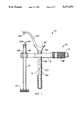
- FIG. 1is an side elevation view of a fixation alignment guide embodying the principles of the instant invention.
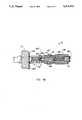
- FIG. 2is an exploded side elevation view of the fixation alignment guide shown in FIG. 1.
- FIG. 3is an end elevation view of the fixation alignment guide shown in FIG. 1.
- FIG. 4is a top plan view of the fixation alignment guide shown in FIG. 1.
- FIGS. 5A and 5Bare vertical cross sectional views of the ratchet mechanism of the fixation alignment guide shown in FIG. 1 in the locked and released positions, respectively.
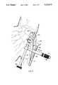
- FIG. 6is an environmental view showing the fixation alignment guide of FIG. 1 employed so as to be engaging a fractured scaphoid bone in the wrist of a patient.
- FIG. 1the fixation alignment guide of the invention which is generally designated 10.
- the fixation alignment guide of the inventionwhich is generally designated 10.
- Fixation alignment guide 10is a novel assembly formed of an axially movable shaft 12, a tubular guide 14, and elongate guide support 16 for fixedly engaging tubular guide 14 at one end thereof and provided with an aperture 16A in the medial portion thereof for slidably receiving axially movable shaft 12 therein.
- a ratchet mechanism 18(see particularly FIGS. 5A and 5B) is carried by elongate guide support 16 which serves to selectively engage and disengage axially movable shaft 12 in a fashion which will be explained in specific detail hereinbelow.
- At least one bushing 20is provided which has a passageway 20A extending therethrough and which is adapted to be inserted into tubular guide 14 as desired to reduce its internal diameter to allow for the precise insertion of primary guide wires (not shown) or the like through tubular guide 14 during use of fixation alignment guide 10 to insert a rigid shaft into opposed segments of a fractured bone, particularly scaphoid and other small bones which lend themselves to use of the device of the invention.
- axially movable shaft 12is formed from an elongate shaft element having an arm 12A extending outwardly therefrom with a pin element 12A' depending downwardly therefrom for engaging a fractured bone at a first location at the far end of the bone.
- Axially movable shaft 12further includes ratchet teeth 12B along a portion of the length of the backside thereof for engagement with ratchet mechanism 18 carried by elongate guide support 16 in a cooperative manner which will be explained in detail below but, for general purposes, can be understood to allow slidable movement of shaft 12 inwardly when finger recess 12C is depressed inwardly toward elongate guide support 16, but to lock when a force is applied to shaft 12 in the opposite direction.
- tubular guide 14terminates in a plurality of teeth or tines 14A to facilitate engagement of the fractured bone at a second bone surface location substantially opposite the engagement at the first surface location by pin 12A' of arm 12A of axially movable shaft 12.
- Tines 14Amay be of any suitable size and number to provide a stable fixation at the second surface engagement location of a fractured bone.
- the distance defined between pin 12A' and tines 14Acan be determined by a suitable scale 12D provided on each side of axially movable shaft 12.
- Scale 12Deliminates the need for measuring the aforementioned critical distance in another way and provides the data necessary for exact and safe adjustment of device 10 in view of the length of the rigid shaft to be inserted.
- fixation alignment guide 10will also accommodate other rigid shafts including, but not limited to, molly-bolt devices, barbed nails, bone grafts, bone dowels and other similar elements.
- the measurement of the distance between tines 14A of tubular guide 14 and pin 12A' of axially movable shaft 12is determined, most suitably, by merely reading the number inscribed on scale 12D at the juncture of scale 12D and aperture 16A of elongate guide support 16 (see, for example, FIG. 1).
- Ratchet mechanism 18essentially comprises spring 18A which is normally urged against a ratchet engagement and disengagement assembly consisting of pivot shaft 18B which is adapted for both axial and rotational movement and which engages ratchet pin 18C which is adapted exclusively for axial movement. Pivot shaft 18B and ratchet pin 18C are cooperatively engaged by bearings 18D which reside within radial groove 18B' of pivot shaft 18B and corresponding radially extending apertures 18C' within ratchet pin 18C.
- pivot shaft 18Burges pivot shaft 18B and ratchet pin 18C inwardly wherein ratchet teeth 18C" of ratchet pin 18C engage ratchet teeth 12B of axially movable shaft 12.
- pivot shaft 18Bis adapted to move both axially and rotationally inwardly ratchet pin 18C can only move axially inwardly by virtue of flat portion F provided on one side thereof and against which set screw S is locked down (and sealed) into a position which allows slidable movement of ratchet pin 18C but which prevents any significant degree of rotational movement in either direction.
- ratchet teeth 18Care always properly oriented to register with the ratchet teeth 12B (or blade) of axially movable shaft 12.
- a set screw 18Eis provided at the remote end of spring 18A and within elongate guide support 16 in order to adjust the tension of spring 18A to a desired level for proper functioning of alignment guide 10.
- axially movable shaft 12may be released for movement in the aforesaid opposite direction by merely simultaneously rotating and pulling upon sleeve 18F in the direction of set screw 18E which serves to disengage ratchet teeth 18C" of ratchet pin 18C from ratchet teeth 12B of movable shaft 12.
- sleeve 18Fincludes an inwardly extending rigid pin 18F, which slides within an arcuate slot SL defined within elongate guide support 16 and terminates in fixed engagement with pivot shaft 18B.
- pin 18F'through an arcuate pathway which thereby serves to both rotate and axially withdraw fixedly connected pivot shaft 18B outwardly toward the end of elongate guide support 16 in which set screw 18E resides.
- Pivot shaft 18Bin turn axially withdraws ratchet pin 18C toward the outside end of elongate guide support 16 so as to release ratchet teeth 18C" from engagement with ratchet teeth 12B of movable shaft 12.
- the ratchet mechanism 18 of fixation alignment guide 10can be seen to allow one-handed locking and unlocking by a physician and/or to allow the physician to keep device 10 in an unlocked position until the locked position is desired.
- elongate guide support 16 of alignment guide 10provides for two parallel passageways or cannulations adjacent tubular guide 14 in elongate guide support 16.
- the cannulations, designated 16B,are intended to provide a passageway for the fixation of accessory wires into the fractured bone to stabilize bone fragments and provide rotational control of bone fragments during the drilling and rigid shaft insert steps required in surgical use of alignment guide 10.
- the arthroscopic procedure for use of alignment guide 10 to address the scaphoid fracture of bone Bwould entail the following recommended procedural steps.
- RMCradial midcarpal
- Advance shaft 12 and arm 12Aunder arthroscopic control between the radius and scaphoid to the appropriate target point on the proximal pole of the scaphoid. This point should be approximately 1-2 mm from the scapholunate ligament along the dorsal aspect of the proximal pole.
- Rotate shaft 12 and arm 12Aso its angle accommodates the convex contour of the scaphoid and embed pin element 12A' of arm 12A into the articular cartilage at the target point. Use slight traction to hold it in place while tubular guide 14 and elongate guide support 16 is attached.
- Wire penetrationcan be controlled using a flat depth gauge to inset the primary guide wire into a wire driver at the correct length. Drive the wire into the bone through the insert sleeve until the wire driver bottoms out on the sleeve. Then remove the wire driver and sleeve.
- an x-ray or image intensifierto verify the positioning of the primary guide wire.
- this stepis not necessary.
- power instrumentscan be used to drive this broach.
- a cannulated step drillover the primary guide wire to drill the pilot hole.
- the holeshould be drilled using a cannulated Jacob's check and power drill.
- the cannulated step drillcan be attached to the modular handle for manual drilling. The small diameter of this drill is for the leading threads of the screw while the larger diameter is for the trailing threads and shank. Drill until the sleeve bottoms out on the end of tubular guide 14.
- a cannulated tapFor sclerotic bone only, attach a cannulated tap to the modular handle. Slide the adjustable stop sleeve onto the tap and set it for the appropriate screw length. Tap the hole for the leading threads of the screw. This is an optional step recommended for sclerotic bone because the leading and trailing threads of the screw implant are self-tapping. Tap until the sleeve bottoms out on the end of tubular guide 14. The tap must not be turned beyond the depth of the sleeve or the bone threads will be stripped.
- the cannulated screwdriverWhen the screw is fully seated, remove the cannulated screwdriver, the primary guide wire, and the alignment guide.
- the accessory guide wirecan also be removed or, if desired, it can be left in place for the first two weeks to help control rotation of the bone fragments during initial healing.
- inspect the entry point on the distal pole of the scaphoidIf necessary, reapply the screwdriver and rotate the screw one more revolution.
Landscapes
- Health & Medical Sciences (AREA)
- Surgery (AREA)
- Life Sciences & Earth Sciences (AREA)
- Biomedical Technology (AREA)
- Medical Informatics (AREA)
- Orthopedic Medicine & Surgery (AREA)
- Oral & Maxillofacial Surgery (AREA)
- Engineering & Computer Science (AREA)
- Dentistry (AREA)
- Heart & Thoracic Surgery (AREA)
- Nuclear Medicine, Radiotherapy & Molecular Imaging (AREA)
- Molecular Biology (AREA)
- Animal Behavior & Ethology (AREA)
- General Health & Medical Sciences (AREA)
- Public Health (AREA)
- Veterinary Medicine (AREA)
- Surgical Instruments (AREA)
Abstract
Description
1. Technical Field
The invention relates to devices particularly adapted for use in orthopaedic surgery, and more specifically to an improved device for joining opposed segments of a fractured bone with a rigid shaft inserted therein.
2. Related Art
As is well known to those familiar with orthopaedic surgical procedures, it is often necessary to secure opposed fractured bone segments together using threaded and/or unthreaded screws and pins. This is a very delicate procedure requiring great surgical skill in order to avoid imposing injury on healthy tissue in proximity to the fractured bone being joined.
Of significance to this type of medical procedure, Dr. Timothy Herbert of Australia developed a unique screw intended primarily for the fixation of fractures of the carpel scaphoid. The screw is the subject matter of U.S. Pat. No. 4,175,555 and comprises threads at opposing ends which are separated by a non-threaded medial segment. The functionality of the screw is provided by the fact that the leading threads define a greater pitch and diameter than the trailing threads of the screw so as to progress through a bone at a higher rate per revolution than the trailing threads and thereby apply a compressive force to opposed segments of a fractured bone. As is also well known to those familiar with orthopaedic surgical procedures, the screw is best inserted by use of an alignment jig developed by Donald R. Huene and the subject matter of U.S. Pat. No. 3,867,932.
The alignment jig disclosed in U.S. Pat. No. 3,867,932 provides an off-set target hook that extends along a small bone and then curves to engage the bone's remote end. A cooperatively associated guide barrel is adapted to slide through the foundation from which the target hook extends to engage the proximal end of the fractured bone, and the guide barrel and target hook can then be locked together to provide compression across the fractured bone. In this fashion, suitable instruments well-known to those skilled in the orthopaedic surgical art are then introduced through the guide barrel including, but not limited to, a twist drill bit, a thread tap, a screw driver and a Herbert Screw. Thus, the Herbert Screw in combination with the Huene alignment jig provide a useful methodology for stabilizing and then transfixing small bone fractures, most notably the carpel scaphoid.
However, the aforementioned system for joining fractured bone segments has certain shortcomings which are well known to those skilled in the art. More specifically, surgical exposure of the carpel scaphoid is usually attained through either a volar or dorsal approach (front or back) and therefore introduction of the Huene guide target hook through the surgical incision necessitated a blind placement of the target hook on the far end of the bone by the surgeon. Furthermore, the introduction of the guide target hook necessitated relatively extensive surgical exposure transecting ligaments that might further destabilize the scaphoid within the wrist or divide its blood supply necessary for fracture healing.
Yet another shortcoming of the prior system using the Herbert Screw and Huene alignment jig was that after inserting the twist drill bit (the first instrument to be passed through the guide barrel and bone) and thereby removing a significant amount of bone, a second adjusted pass was not possible with any assurance of desirable thread purchase in solid bone. In actual practice, many such Herbert Screw placements in clinical practice exit the bone entirely, miss the remote bone fragment, violate the external cortex or articular surface of the bone, or do not achieve satisfactory purchase for rigid fixation. Thus, as can be appreciated, the Huene alignment jig as disclosed in U.S. Pat. No. 3,867,932 suffers inherent shortcomings when actually used in surgical procedures.
Therefore, applicant has developed an improved fixation alignment guide which overcomes the shortcomings of prior art alignment jigs used in joining opposing segments of a fractured bone with screws (including both the Herbert Screw and the Herbert/Whipple Screw disclosed in U.S. Pat. No. 5,019,079), pins, wire and the like while protecting contiguous tissue from damage. More particularly, applicant has developed a fixation alignment guide which is adapted so that one element thereof can be introduced percutaneously under arthroscopic control to engage the distal end of a fractured bone and thereby provide a minimally invasive technique with the attendant reduced surgical exposure, preservation of ligaments, and preservation of clinical blood supply to the bone coursing through the ligaments.
In accordance with the present invention applicant provides a fixation alignment guide for surgical use, particularly for fixation of scaphoid and other small bone fractures. The device comprises an axially movable shaft having an arm extending outwardly therefrom which is adapted to engage a fractured bone at a first surface location. A tubular guide is operatively aligned with the bone engagement arm and has a proximal end and a distal end wherein the proximal end comprises jaw means for engaging the fractured bone at a second surface location substantially opposite the first bone surface location. An elongate guide support is provided for engaging the tubular guide between the proximal and distal ends thereof and further defines an aperture therethrough for movably receiving the axially movable shaft therein. Securement means are operatively associated with the guide support for securing the axially movable shaft at a desired distance from the jaw means of the tubular guide in order to fixedly engage the fractured bone therebetween whereby rigid shafts may be inserted through the tubular guide and implanted into the opposed segments of a fractured bone.
It is therefore the object of the present invention to provide an improved fixation alignment guide for better joining of opposed segments of a fractured bone by means of insertion of a rigid shaft into opposing segments thereof.
It is another object of the present invention to provide an improved fixation alignment guide for joining opposed segments of a fractured bone which in use minimizes necessary surgical exposure by allowing the axially movable shaft portion thereof to be introduced percutaneously under arthroscopic control so as to engage the far end of a fractured bone.
It is still another object of the present invention to provide an improved fixation alignment guide which is adapted for insertion of a primary guide wire through the bone and the correct position thereof confirmed radiographically, and the insertion of one or more accessory guide wires through the bone to control rotation of the device and/or to provide additional stabilization of bone fragments during subsequent surgical procedures performed therewith.
Some of the objects of the invention having been stated other objects will become evident as the description proceeds, when taken in connection with the accompanying drawings described hereinbelow.
FIG. 1 is an side elevation view of a fixation alignment guide embodying the principles of the instant invention.
FIG. 2 is an exploded side elevation view of the fixation alignment guide shown in FIG. 1.
FIG. 3 is an end elevation view of the fixation alignment guide shown in FIG. 1.
FIG. 4 is a top plan view of the fixation alignment guide shown in FIG. 1.
FIGS. 5A and 5B are vertical cross sectional views of the ratchet mechanism of the fixation alignment guide shown in FIG. 1 in the locked and released positions, respectively.
FIG. 6 is an environmental view showing the fixation alignment guide of FIG. 1 employed so as to be engaging a fractured scaphoid bone in the wrist of a patient.
Referring now more specifically to FIGS. 1-6 of the drawings wherein like references designate like or corresponding parts in each of the figures, there is shown in FIG. 1 the fixation alignment guide of the invention which is generally designated 10. However, applicant wishes to observe that although the preferred embodiment of the invention is shown and described herein, it is recognized that various details of the invention may be changed without departing from the scope of the invention, and the scope of the invention is not intended to be limited in any fashion whatsoever to the illustrative details and preferred embodiment disclosed herein.
Referring now particularly to FIGS. 1-4, axiallymovable shaft 12 is formed from an elongate shaft element having anarm 12A extending outwardly therefrom with apin element 12A' depending downwardly therefrom for engaging a fractured bone at a first location at the far end of the bone. Axiallymovable shaft 12 further includesratchet teeth 12B along a portion of the length of the backside thereof for engagement withratchet mechanism 18 carried byelongate guide support 16 in a cooperative manner which will be explained in detail below but, for general purposes, can be understood to allow slidable movement ofshaft 12 inwardly when finger recess 12C is depressed inwardly towardelongate guide support 16, but to lock when a force is applied toshaft 12 in the opposite direction.
Referring now more specifically totubular guide 14, it can be appreciated that the tubular guide terminates in a plurality of teeth ortines 14A to facilitate engagement of the fractured bone at a second bone surface location substantially opposite the engagement at the first surface location bypin 12A' ofarm 12A of axiallymovable shaft 12. Tines 14A may be of any suitable size and number to provide a stable fixation at the second surface engagement location of a fractured bone.
At this part of the description, it should also be noted that the distance defined betweenpin 12A' andtines 14A (or the first and second bone engagement surfaces) can be determined by asuitable scale 12D provided on each side of axiallymovable shaft 12.Scale 12D eliminates the need for measuring the aforementioned critical distance in another way and provides the data necessary for exact and safe adjustment ofdevice 10 in view of the length of the rigid shaft to be inserted. In this regard, althoughdevice 10 is particularly adapted for insertion of the Herbert Screw and Herbert/Whipple Screw,fixation alignment guide 10 will also accommodate other rigid shafts including, but not limited to, molly-bolt devices, barbed nails, bone grafts, bone dowels and other similar elements. The measurement of the distance betweentines 14A oftubular guide 14 andpin 12A' of axiallymovable shaft 12 is determined, most suitably, by merely reading the number inscribed onscale 12D at the juncture ofscale 12D andaperture 16A of elongate guide support 16 (see, for example, FIG. 1).
Finally, for an understanding of the structure and functionality ofratchet mechanism 18, reference should now be made to FIGS. 5A and 5B.Ratchet mechanism 18 essentially comprisesspring 18A which is normally urged against a ratchet engagement and disengagement assembly consisting ofpivot shaft 18B which is adapted for both axial and rotational movement and which engagesratchet pin 18C which is adapted exclusively for axial movement.Pivot shaft 18B and ratchetpin 18C are cooperatively engaged bybearings 18D which reside withinradial groove 18B' ofpivot shaft 18B and corresponding radially extendingapertures 18C' withinratchet pin 18C. In this fashion,spring 18A urgespivot shaft 18B and ratchetpin 18C inwardly wherein ratchetteeth 18C" ofratchet pin 18C engageratchet teeth 12B of axiallymovable shaft 12. Thus, whereaspivot shaft 18B is adapted to move both axially and rotationally inwardly ratchetpin 18C can only move axially inwardly by virtue of flat portion F provided on one side thereof and against which set screw S is locked down (and sealed) into a position which allows slidable movement ofratchet pin 18C but which prevents any significant degree of rotational movement in either direction. This is necessary to assure that ratchetteeth 18C" are always properly oriented to register with theratchet teeth 12B (or blade) of axiallymovable shaft 12. Also, aset screw 18E is provided at the remote end ofspring 18A and withinelongate guide support 16 in order to adjust the tension ofspring 18A to a desired level for proper functioning ofalignment guide 10.
Still referring to FIGS. 5A and 5B and ratchetmechanism 18, it can be appreciated that as axiallymovable shaft 12 is urged towardelongate guide support 16 it will advance due to slidable movement ofratchet teeth 12B ofshaft 12 overratchet teeth 18C" ofratchet pin 18C, but movement in the opposite direction is prevented by the flat edges of engagedratchet teeth movable shaft 12 may be released for movement in the aforesaid opposite direction by merely simultaneously rotating and pulling uponsleeve 18F in the direction ofset screw 18E which serves to disengageratchet teeth 18C" ofratchet pin 18C from ratchetteeth 12B ofmovable shaft 12.
This is accomplished sincesleeve 18F includes an inwardly extendingrigid pin 18F, which slides within an arcuate slot SL defined withinelongate guide support 16 and terminates in fixed engagement withpivot shaft 18B. In this fashion, whensleeve 18F is pulled outwardly and rotated it serves to pullpin 18F' through an arcuate pathway which thereby serves to both rotate and axially withdraw fixedly connectedpivot shaft 18B outwardly toward the end ofelongate guide support 16 in whichset screw 18E resides.Pivot shaft 18B in turn axially withdrawsratchet pin 18C toward the outside end ofelongate guide support 16 so as to release ratchetteeth 18C" from engagement withratchet teeth 12B ofmovable shaft 12. Whensleeve 18F has been fully rotated and pulled toward the outer end of elongate guide support 16 (see FIG. 5B) it serves to lockpivot shaft 18B and ratchetpin 18C into the withdrawn or released position by virtue ofpin 18F' which is affixed to pivotshaft 18B at one end andsleeve 18F at the other. The process is merely reversed in order to change alignment guide 10 from the unlocked (FIG. 5A) to the locked (FIG. 5B) mode whereby movement ofshaft 12 will be permitted in one direction but stopped in the other.
In this fashion, theratchet mechanism 18 offixation alignment guide 10 can be seen to allow one-handed locking and unlocking by a physician and/or to allow the physician to keepdevice 10 in an unlocked position until the locked position is desired.
Finally, with reference particularly to FIG. 1 and 4 of the drawings, it can be appreciated thatelongate guide support 16 ofalignment guide 10 provides for two parallel passageways or cannulations adjacenttubular guide 14 inelongate guide support 16. The cannulations, designated 16B, are intended to provide a passageway for the fixation of accessory wires into the fractured bone to stabilize bone fragments and provide rotational control of bone fragments during the drilling and rigid shaft insert steps required in surgical use ofalignment guide 10.
Applicant believes that one skilled in the art would fully understand use ofdevice 10 from the foregoing detailed description. However, applicant desires to describe briefly a representative surgical procedure utilizing the device of the invention. It will be appreciated, of course, by those skilled in the art that many other procedures can be performed withdevice 10 and the procedure to be described hereinbelow is merely intended to be representative and in no manner to limit the scope of potential uses of the invention.
The arthroscopic procedure for use ofalignment guide 10 to address the scaphoid fracture of bone B (see particularly FIG. 6) would entail the following recommended procedural steps.
Use either regional or general anesthesia. Apply a tourniquet, and prepare and drape the limb in the standard fashion. The use of an arm extension table and a traction tower, or similar traction arrangement, is recommended.
Make a 12 to 15 mm incision, centered over the volar tubercle of the trapezium just radial to the flexor carpi radialis tendon. Identify and open the scaphotrapezial joint through a transverse capsulotomy. Make a T-shaped incision in the capsule and periosteum over the trapezium, meeting the transverse capsulotomy. Turn the capsular flaps distally by subperiosteal dissection.
Excise the volar tubercle on the trapezium with a 3/16 inch osteotome. Remove enough of the tubercle to expose a portion of the distal pole of the scaphoid when the first metacarpal is hyperextended. Place a small self-retaining retractor in the incision. Position the forearm vertically in the traction tower with 10 pounds of axial traction applied to the index and long fingers.
Gently introduce the arthroscope through the radial midcarpal (RMC) portal. To avoid applying excessive pressure during insertion of the arthroscope sheath and trocar, spread the subcutaneous tissue and lance the capsule with a No. 11 scalpel. Briefly flush the joint.
Insert an inflow cannula in the ulnar midcarpal (UMC) portal. Be sure it will not interfere with instrumentation. Clear the hemarthrosis, if present, and examine the fracture line for any evidence of displacement or angulation. If the degree of angulation or displacement is small, reduce the fracture by placing the wrist in extension or supination. This should reverse the humpback deformity and close the fracture line. If the fracture line remains open, inset a 0.045 inch K-wire percutaneously into the scaphoid tubercle volarly and into the proximal pole dorsally. Use these wires to manipulate the fracture fragments. Confirm the reduction using a radiograph or fluoroscope.
Step 1--Insert Alignment Guide
Transfer the arthroscope to the 3-4 portal and move the inflow cannula to the arthroscopy sheath or the 6-U portal. Establish a 1-2 portal and dilate it to admit the axiallymovable shaft 12 andarm 12A of the alignment guide.
Hyperextend the thumb to displace the trapezium dorsally on the distal articular surface of the scaphoid. Swingtubular guide 14 ofalignment guide 10 into position on the radial aspect of the distal pole of the scaphoid. Squeezemovable shaft 12 towardtubular guide 14 to push thetines 14A of the tubular guide onto the bone.
When thealignment guide 10 has been applied, check its alignment visually to ensure that the screw to be inserted will lie in the optimum position. Also check the reduction of the fracture and make any necessary adjustments. If an adjustment is necessary compression can be released by pullingsleeve 18F ofratchet mechanism 18 onalignment guide 10.
Step 2--Determine Screw Length
Read the screw length fromscale 12D ofmovable shaft 12 for the calibrations of the guide.
Step 3--Insert Wires
Insert a free-hand guide insert sleeve orbushing 20 intotubular guide 14 of the alignment guide. Wire penetration can be controlled using a flat depth gauge to inset the primary guide wire into a wire driver at the correct length. Drive the wire into the bone through the insert sleeve until the wire driver bottoms out on the sleeve. Then remove the wire driver and sleeve.
Use an x-ray or image intensifier to verify the positioning of the primary guide wire. There should be at least 2.0 mm of bone on both sides of the wire in every projection. If necessary withdraw the wire, reposition the alignment guide, and reinsert the wire.
Use a depth gauge to insert the accessory guide wire into a wire driver at the correct depth. Place this wire parallel to the primary wire through one of twocannulations 16B adjacent totubular guide 14 ofalignment guide 10. This will help prevent fragment rotation during screw insertion. Drive the wire until the wire driver bottoms out on the end oftubular guide 14. Then bend the accessory wire away fromtubular guide 14 to remove it from the path of the instruments.
Step 4--Broach the Cortex
For thin cortex, or osteoporotic bone, this step is not necessary. For hard bone, attach a cannulated cortical broach to a modular handle and slide it over the primary guide wire. Turn the handle clockwise and advance the broach until it bottoms out on the end oftubular guide 14. This will remove a small amount of bone from the cortical surface and facilitate further instrumentation. Alternatively, power instruments can be used to drive this broach.
Step 5--Drill
Use a cannulated step drill over the primary guide wire to drill the pilot hole. Slide an adjustable stop sleeve onto the drill and set it for the appropriate screw length. The hole should be drilled using a cannulated Jacob's check and power drill. Alternatively, for soft bone, the cannulated step drill can be attached to the modular handle for manual drilling. The small diameter of this drill is for the leading threads of the screw while the larger diameter is for the trailing threads and shank. Drill until the sleeve bottoms out on the end oftubular guide 14.
For sclerotic bone only, attach a cannulated tap to the modular handle. Slide the adjustable stop sleeve onto the tap and set it for the appropriate screw length. Tap the hole for the leading threads of the screw. This is an optional step recommended for sclerotic bone because the leading and trailing threads of the screw implant are self-tapping. Tap until the sleeve bottoms out on the end oftubular guide 14. The tap must not be turned beyond the depth of the sleeve or the bone threads will be stripped.
Step 7--Insert the Screw
Attach a cannulated screwdriver to the modular handle. Insert the screw and screwdriver over the guide wire and intotubular guide 14 ofalignment guide 10. Turn the screwdriver until the stop bottoms out on the end oftubular guide 14. The screwdriver should be advanced a few more times to further bury the screw head below the bone surface.
When the screw is fully seated, remove the cannulated screwdriver, the primary guide wire, and the alignment guide. The accessory guide wire can also be removed or, if desired, it can be left in place for the first two weeks to help control rotation of the bone fragments during initial healing. To ensure that the screw head is completely buried, inspect the entry point on the distal pole of the scaphoid. If necessary, reapply the screwdriver and rotate the screw one more revolution.
Finally, put the wrist joint through a full range of movements to check the security of fixation and to ensure that the screw has not penetrated proximally. This can also be checked by reinserting the arthroscope in the 3-4 portal. Carefully trim off any protuberant bone graft.
It will be understood that various details of the invention may be changed without departing from the scope of the invention. Furthermore, the foregoing description is for the purpose of illustration only, and not for the purpose of limitation--the invention being defined by the claims.
Claims (13)
1. A device for inserting rigid shafts into opposed segments of a fractured bone the device comprising:
an axially movable shaft having an arm extending outwardly therefrom said arm being adapted to engage a fractured bone at a first surface location;
a tubular guide operatively aligned with said bone engagement arm and having a proximal end and a distal end wherein said proximal end comprises means for engaging the fractured bone at a second surface location substantially opposite said first bone surface location;
an elongated guide support for engaging said tubular guide between the proximal and distal ends of said tubular guide and defining an aperture therethrough for adjustably receiving said axially movable shaft therein; and
securement means operatively associated with said guide support for securing said axially movable shaft at a desired distance from said engagement means of said tubular guide in order to fixedly engage the fractured bone therebetween;
whereby rigid shafts may be inserted through said tubular guide and implanted into opposed segments of the fractured bone, and
wherein said elongate guide support includes one or more apertures therethrough located adjacent and parallel to said tubular guide, said apertures defining a smaller diameter passageway than said tubular guide and allowing for selective insertion of guide wires into the fractured bone.
2. A device for inserting rigid shafts into opposed segments of a fractured bone the device comprising:
an axially movable shaft having an arm extending outwardly therefrom, said are being adapted to engage a fractured bone at a first surface location;
a tubular guide operatively aligned with said bone engagement arm and having a proximal end and a distal end wherein said proximal end comprises means for engaging the fractured bone at a second surface location substantially opposite said first bone surface location;
an elongate guide support for engaging said tubular guide between the proximal and distal ends of said tubular guide and defining an aperture therethrough for adjustably receiving said axially movable shaft therein; and
securement means operatively associated with said guide support for securing said axially movable shaft at a desired distance from said engagement means of said tubular guide in order to fixedly engage the fractured bone therebetween;
whereby rigid shafts may be inserted through said tubular guide and implanted into opposed segments of the fractured bond, and
wherein said securement means comprises:
a. ratchet teeth provided along at least a portion of the length of said axially movable shaft;
b. a ratchet pin carried by said elongate guide support and said ratchet pin to cooperatively engage said ratchet teeth of said axially movable shaft so as to allow said shaft to be slidably movable relative thereto in one direction and to lockingly engage said shaft so as to prevent slidable movement of said shaft in the other direction;
c. a sleeve rotatably mounted to said elongate guide support in spaced apart relationship to said axially movable shaft; and
d. connector means operatively connecting said sleeve to said ratchet pin and adapted to withdraw said ratchet pin from cooperative engagement with said ratchet teeth of said axially movable shaft when said sleeve is rotatably actuated and thereby release said axially movable shaft for slidable movement in said one direction and said other direction.
3. A device for inserting rigid shafts into opposed segments of a fractured bone the device comprising:
an axially movable shaft having an arm extending outwardly therefrom, said arm being adapted to engage a fractured bone at a first surface location;
a tubular guide operatively aligned with said bone engagement arm and having a proximal end and a distal end wherein said proximal end comprises means for engaging the fractured bone at a second surface location substantially opposite said first bone surface location;
an elongate guide support for engaging said tubular guide between the proximal and distal ends of said tubular guide and defining an aperture therethrough for adjustably receiving said axially movable shaft therein; and
securement means operatively associated with said guide support for securing said axially movable shaft at a desired distance from said engagement means of said tubular guide in order to fixedly engage the fractured bone therebetween;
whereby rigid shafts may be inserted through said tubular guide and implanted into opposed segments of the fractured bone, and
wherein a bushing defining an aperture therethrough is provided which is inserted into said tubular guide to provide a reduced diameter passageway through said tubular guide for insertion of a guide wire into the fractured bone.
4. A device for inserting rigid shafts into opposed segments of a fractured bone, the device comprising;
an axially movable shaft having an arm extending outwardly therefrom, said arm being adapted to engage a fractured bone at a first surface location and said arm having a base;
a tubular guide operatively aligned with said bone engagement arm and having a proximal end and a distal end wherein said proximal end comprises jaw means for engaging the fractured bone at a second surface location substantially opposite said first bone surface location;
an elongate guide support for engaging said tubular guide between the proximal and distal ends of said tubular guide and defining an aperture therethrough for slidably receiving said axially movable shaft therein; and
securement means operatively associated with said guide support for securing said axially movable shaft at a desired distance from said jaw means of said tubular guide in order to fixedly engage the fractured bone therebetween, said securement means comprising: (1) ratchet teeth provided along at least a portion of the length of said axially movable shaft; (2) a ratchet pin carried by said elongate guide support and said ratchet pin to cooperatively engage said ratchet teeth of said axially movable shaft so as to allow said shaft to be slidably movable relative thereto in one direction and to lockingly engage said shaft so as to prevent slidable movement of said shaft in the other direction; (3) a sleeve rotatably mounted to said elongate guide support in spaced apart relationship to said axially movable shaft; and (4) connector means operatively connecting said sleeve to said ratchet pin and adapted to withdraw said ratchet pin from cooperative engagement with said ratchet teeth of said axially movable shaft when said sleeve is rotatably actuated and thereby release said axially movable shaft for slidable movement in said one direction and said other direction;
whereby rigid shafts may be inserted through said tubular guide and implanted into opposed segments of the fractured bone.
5. A device according to claim 4 wherein said arm of said axially movable shaft includes a pin element for engagement of the bone depending downwardly from the free end thereof and substantially axially aligned with said tubular guide.
6. A device according to claim 4 wherein said axially movable shaft includes measuring means for indicating the distance between said first bone surface location engaged by said arm thereof and said second bone surface engaged by said jaw means of said tubular guide.
7. A device according to claim 6 wherein said measuring means is a scale inscribed on said axially movable shaft.
8. A device according to claim 4 wherein said axially movable shaft includes an arcuate finger receiving portion at the base of said arm to facilitate slidably urging said shaft towards said elongate guide support.
9. A device according to claim 4 wherein said axially movable shaft extends substantially pendicularly in relationship to said elongate guide support and substantially parallel to said tubular guide.
10. A device according to claim 4 wherein said jaw means of said tubular guide comprises a plurality of tines extending generally outwardly from said proximal end of said tubular guide and parallel to a longitudinal axis thereof.
11. A device according to claim 4 wherein said elongate guide support fixedly engages said tubular guide adjacent one end thereof, slidably receives said axially movable shaft substantially in the medial portion thereof, and carries said securement means between the other end thereof and said axially movable shaft.
12. A device according to claim 12 wherein said elongate guide support includes one or more apertures therethrough located adjacent and parallel to said tubular guide, said apertures defining a smaller diameter passageway than said tubular guide and allowing for selective insertion of guide wires into the fractured bone.
13. A device according to claim 4 wherein a bushing defining an aperture therethrough is provided which is inserted into said tubular guide to provide a reduced diameter passageway through said tubular guide for insertion of a guide wire into the fractured bone.
Priority Applications (1)
| Application Number | Priority Date | Filing Date | Title |
|---|---|---|---|
| US08/012,994US5312412A (en) | 1993-02-03 | 1993-02-03 | Fixation alignment guide for surgical use |
Applications Claiming Priority (1)
| Application Number | Priority Date | Filing Date | Title |
|---|---|---|---|
| US08/012,994US5312412A (en) | 1993-02-03 | 1993-02-03 | Fixation alignment guide for surgical use |
Publications (1)
| Publication Number | Publication Date |
|---|---|
| US5312412Atrue US5312412A (en) | 1994-05-17 |
Family
ID=21757751
Family Applications (1)
| Application Number | Title | Priority Date | Filing Date |
|---|---|---|---|
| US08/012,994Expired - LifetimeUS5312412A (en) | 1993-02-03 | 1993-02-03 | Fixation alignment guide for surgical use |
Country Status (1)
| Country | Link |
|---|---|
| US (1) | US5312412A (en) |
Cited By (101)
| Publication number | Priority date | Publication date | Assignee | Title |
|---|---|---|---|---|
| WO1995014433A1 (en)* | 1993-11-24 | 1995-06-01 | Orthopaedic Innovations, Inc. | Cannulated instrumentation for total joint arthroplasty and method of use |
| US5437677A (en)* | 1992-10-09 | 1995-08-01 | Minnesota Mining And Manufacturing Company | Glenoid alignment guide |
| US5584839A (en)* | 1994-12-12 | 1996-12-17 | Gieringer; Robert E. | Intraarticular drill guide and arthroscopic methods |
| US5613971A (en)* | 1995-08-11 | 1997-03-25 | Depuy Inc. | Ratcheting tibial and femoral guide |
| US5624446A (en)* | 1992-09-11 | 1997-04-29 | University Of Washington | System for repair of capsulo-labral separations |
| US5800437A (en)* | 1993-11-24 | 1998-09-01 | Orthopaedic Innovations, Inc. | Cannulated tamp and centering rod for total joint arthroplasty |
| US5885300A (en)* | 1996-04-01 | 1999-03-23 | Asahi Kogaku Kogyo Kabushiki Kaisha | Guide apparatus of intervertebral implant |
| US6419678B1 (en)* | 2000-11-28 | 2002-07-16 | Wilson T. Asfora | Curved drill guide system |
| WO2002096294A2 (en) | 2001-05-29 | 2002-12-05 | Synthes (U.S.A.) | Bone alignment lever |
| US20030074005A1 (en)* | 2001-10-17 | 2003-04-17 | Roth Christoph A. | Orthopedic implant insertion instruments |
| US6585740B2 (en) | 1998-11-26 | 2003-07-01 | Synthes (U.S.A.) | Bone screw |
| US20030153910A1 (en)* | 2002-02-11 | 2003-08-14 | Pioneer Laboratories, Inc. | External fixation apparatus and method |
| US20030236522A1 (en)* | 2002-06-21 | 2003-12-25 | Jack Long | Prosthesis cavity cutting guide, cutting tool and method |
| US20030236525A1 (en)* | 2002-06-21 | 2003-12-25 | Vendrely Timothy G. | Prosthesis removal cutting guide, cutting tool and method |
| US6669698B1 (en) | 2000-10-24 | 2003-12-30 | Sdgi Holdings, Inc. | Vertebrae fastener placement guide |
| JP3520091B2 (en) | 1995-02-07 | 2004-04-19 | デピュー・オーソピーディクス・インコーポレーテッド | Surgical implantation of a cartilage repair unit |
| US20050015092A1 (en)* | 2003-07-16 | 2005-01-20 | Rathbun David S. | Plating system with multiple function drill guide |
| US20050027301A1 (en)* | 2003-08-01 | 2005-02-03 | Pascal Stihl | Drill guide assembly for a bone fixation device |
| US20050038444A1 (en)* | 2003-08-13 | 2005-02-17 | Binder Lawrence J. | Quick-release drill-guide assembly for bone-plate |
| US20050070898A1 (en)* | 2003-09-26 | 2005-03-31 | Jones Michael C. | Radial impaction bone tamp and associated method |
| US20050251265A1 (en)* | 2004-05-07 | 2005-11-10 | Calandruccio James H | Trapezium implant for thumb and method |
| US20060064106A1 (en)* | 2004-09-23 | 2006-03-23 | Fernandez Alberto A | Coplanar X-ray guided aiming arm for locking of intramedullary nails |
| US20070122233A1 (en)* | 2005-10-27 | 2007-05-31 | Brainlab Ag | Device for fixing a reference element |
| JP2007515990A (en)* | 2003-06-20 | 2007-06-21 | アキュームド・エルエルシー | Bone plate with openings that are threaded during surgery |
| US20080306554A1 (en)* | 2007-06-11 | 2008-12-11 | Mckinley Laurence M | Osseointegration and biointegration coatings for bone screw implants |
| US20090069846A1 (en)* | 2006-04-21 | 2009-03-12 | Imperial Innovations Limited | Tendon repair |
| WO2009155111A1 (en) | 2008-05-30 | 2009-12-23 | Wright Medical Technology, Inc. | Drill guide assembly |
| WO2009091615A3 (en)* | 2008-01-18 | 2009-12-30 | Spinecore, Inc. | Instruments and methods for inserting artificial intervertebral implants |
| US7717945B2 (en) | 2002-07-22 | 2010-05-18 | Acumed Llc | Orthopedic systems |
| US20120116402A1 (en)* | 2009-01-23 | 2012-05-10 | Biomet Sports Medicine, Llc | Apparatus and Method for Arthroscopic Transhumeral Rotator Cuff Repair |
| WO2013049656A1 (en) | 2011-09-30 | 2013-04-04 | The Trustees Of Columbia University In The City Of New York | Systems and devices for the reduction and association of bones |
| WO2014152535A1 (en)* | 2013-03-14 | 2014-09-25 | Wright Medical Technology, Inc. | Ankle replacement system and method |
| US20140343556A1 (en)* | 2013-05-15 | 2014-11-20 | F.H. Inc. | Device for guiding piercing tools for placing a glenoid implant |
| US8979850B2 (en) | 2010-06-03 | 2015-03-17 | Clear Surgical Limited | Surgical guide device |
| US9198676B2 (en) | 2011-07-26 | 2015-12-01 | Howmedica Osteonics Corp. | PCL guides for drilling tibial and femoral tunnels |
| JP2016067939A (en)* | 2014-09-30 | 2016-05-09 | メドス・インターナショナル・エスエイアールエルMedos International SARL | Surgical guide for use in ligament repair procedures |
| US9408646B2 (en) | 2003-09-03 | 2016-08-09 | DePuy Synthes Products, Inc. | Bone plate with captive clips |
| AU2015227396B2 (en)* | 2010-07-20 | 2016-08-11 | Ingenium, Llc | Apparatus and Method for Arthroscopic Transhumeral Rotator Cuff Repair |
| US9414870B2 (en) | 2003-09-03 | 2016-08-16 | DePuy Synthes Products, Inc. | Translatable carriage fixation system |
| US9480571B2 (en) | 2012-12-27 | 2016-11-01 | Wright Medical Technology, Inc. | Ankle replacement system and method |
| US9521999B2 (en) | 2005-09-13 | 2016-12-20 | Arthrex, Inc. | Fully-threaded bioabsorbable suture anchor |
| US9526493B2 (en) | 1999-02-02 | 2016-12-27 | Arthrex, Inc. | Suture anchor with insert-molded rigid member |
| WO2017048826A1 (en)* | 2015-09-14 | 2017-03-23 | Radicle Orthopaedics | Methods, instruments and implants for scapho-lunate reconstruction |
| US9622805B2 (en) | 2015-08-14 | 2017-04-18 | Treace Medical Concepts, Inc. | Bone positioning and preparing guide systems and methods |
| US9622739B2 (en) | 2004-04-06 | 2017-04-18 | Arthrex, Inc. | Suture anchor |
| US9687250B2 (en) | 2015-01-07 | 2017-06-27 | Treace Medical Concepts, Inc. | Bone cutting guide systems and methods |
| US9907561B2 (en) | 2012-12-27 | 2018-03-06 | Wright Medical Technologies, Inc. | Ankle replacement system and method |
| US9918724B2 (en) | 2012-12-27 | 2018-03-20 | Wright Medical Technology, Inc. | Ankle replacement system and method |
| US9974588B2 (en) | 2012-12-27 | 2018-05-22 | Wright Medical Technology, Inc. | Ankle replacement system and method |
| US10342590B2 (en) | 2015-08-14 | 2019-07-09 | Treace Medical Concepts, Inc. | Tarsal-metatarsal joint procedure utilizing fulcrum |
| US10357260B2 (en) | 2015-11-02 | 2019-07-23 | First Ray, LLC | Orthopedic fastener, retainer, and guide methods |
| US10376367B2 (en) | 2015-07-02 | 2019-08-13 | First Ray, LLC | Orthopedic fasteners, instruments and methods |
| US10426459B2 (en) | 2016-07-05 | 2019-10-01 | Mortise Medical, LLC | Extra joint stabilization construct |
| US10512470B1 (en) | 2016-08-26 | 2019-12-24 | Treace Medical Concepts, Inc. | Osteotomy procedure for correcting bone misalignment |
| US10524808B1 (en) | 2016-11-11 | 2020-01-07 | Treace Medical Concepts, Inc. | Devices and techniques for performing an osteotomy procedure on a first metatarsal to correct a bone misalignment |
| US10555757B2 (en) | 2014-07-15 | 2020-02-11 | Treace Medical Concepts, Inc. | Bone positioning and cutting system and method |
| US10575862B2 (en) | 2015-09-18 | 2020-03-03 | Treace Medical Concepts, Inc. | Joint spacer systems and methods |
| WO2020076376A1 (en)* | 2018-10-12 | 2020-04-16 | Conmed Corporation | Drill guide assembly |
| US10639050B2 (en)* | 2017-10-02 | 2020-05-05 | Robin Kamal | System and method for interosseous ligament reconstruction |
| US10653467B2 (en) | 2015-05-06 | 2020-05-19 | Treace Medical Concepts, Inc. | Intra-osseous plate system and method |
| US10849663B2 (en) | 2015-07-14 | 2020-12-01 | Treace Medical Concepts, Inc. | Bone cutting guide systems and methods |
| US10849631B2 (en) | 2015-02-18 | 2020-12-01 | Treace Medical Concepts, Inc. | Pivotable bone cutting guide useful for bone realignment and compression techniques |
| US10874446B2 (en) | 2015-07-14 | 2020-12-29 | Treace Medical Concepts, Inc. | Bone positioning guide |
| US10905442B2 (en) | 2014-09-30 | 2021-02-02 | Medos International Sàrl | Side-loading carriage for use in surgical guide |
| US10939939B1 (en) | 2017-02-26 | 2021-03-09 | Treace Medical Concepts, Inc. | Fulcrum for tarsal-metatarsal joint procedure |
| US10993730B2 (en) | 2014-09-30 | 2021-05-04 | Medos International Sàrl | Universal surgical guide systems and methods |
| US11141175B2 (en) | 2014-09-30 | 2021-10-12 | Medos International Saárl | Gage for limiting distal travel of drill pin |
| US11278337B2 (en) | 2015-08-14 | 2022-03-22 | Treace Medical Concepts, Inc. | Tarsal-metatarsal joint procedure utilizing fulcrum |
| US11285300B2 (en) | 2015-08-12 | 2022-03-29 | Vesatek, Llc | System and method for manipulating an elongate medical device |
| US11311302B2 (en) | 2012-12-27 | 2022-04-26 | Wright Medical Technology, Inc. | Ankle replacement system and method |
| US11583323B2 (en) | 2018-07-12 | 2023-02-21 | Treace Medical Concepts, Inc. | Multi-diameter bone pin for installing and aligning bone fixation plate while minimizing bone damage |
| US11596443B2 (en) | 2018-07-11 | 2023-03-07 | Treace Medical Concepts, Inc. | Compressor-distractor for angularly realigning bone portions |
| US11607250B2 (en) | 2019-02-13 | 2023-03-21 | Treace Medical Concepts, Inc. | Tarsal-metatarsal joint procedure utilizing compressor-distractor and instrument providing sliding surface |
| US11622797B2 (en) | 2020-01-31 | 2023-04-11 | Treace Medical Concepts, Inc. | Metatarsophalangeal joint preparation and metatarsal realignment for fusion |
| US11627954B2 (en) | 2019-08-07 | 2023-04-18 | Treace Medical Concepts, Inc. | Bi-planar instrument for bone cutting and joint realignment procedure |
| US11857207B2 (en) | 2016-03-23 | 2024-01-02 | Wright Medical Technology, Inc. | Circular fixator system and method |
| USD1011524S1 (en) | 2022-02-23 | 2024-01-16 | Treace Medical Concepts, Inc. | Compressor-distractor for the foot |
| US11872137B2 (en) | 2021-06-15 | 2024-01-16 | Wright Medical Technology, Inc. | Unicompartmental ankle prosthesis |
| US11889998B1 (en) | 2019-09-12 | 2024-02-06 | Treace Medical Concepts, Inc. | Surgical pin positioning lock |
| US11890039B1 (en) | 2019-09-13 | 2024-02-06 | Treace Medical Concepts, Inc. | Multi-diameter K-wire for orthopedic applications |
| US11931106B2 (en) | 2019-09-13 | 2024-03-19 | Treace Medical Concepts, Inc. | Patient-specific surgical methods and instrumentation |
| US11986251B2 (en) | 2019-09-13 | 2024-05-21 | Treace Medical Concepts, Inc. | Patient-specific osteotomy instrumentation |
| US12004789B2 (en) | 2020-05-19 | 2024-06-11 | Treace Medical Concepts, Inc. | Devices and techniques for treating metatarsus adductus |
| US12114872B2 (en) | 2021-03-30 | 2024-10-15 | Wright Medical Technology, Inc. | Alignment guide, systems, and methods |
| USD1051382S1 (en) | 2022-02-23 | 2024-11-12 | Treace Medical Concepts, Inc. | Lesser metatarsal cut guide |
| US12161371B2 (en) | 2021-01-18 | 2024-12-10 | Treace Medical Concepts, Inc. | Contoured bone plate with locking screw for bone compression, particularly across a tarsometatarsal joint |
| USD1057155S1 (en) | 2022-02-23 | 2025-01-07 | Treace Medical Concepts, Inc. | Lesser metatarsal cut guide with parallel cut faces |
| US12196856B2 (en) | 2021-06-09 | 2025-01-14 | Wright Medical Technology | Alignment systems and methods |
| US12193683B2 (en) | 2021-05-20 | 2025-01-14 | Treace Medical Concepts, Inc. | Cut guide with integrated joint realignment features |
| US12201538B2 (en) | 2021-09-21 | 2025-01-21 | Wright Medical Technology, Inc. | Expanding tibial stem |
| US12239539B2 (en) | 2021-06-07 | 2025-03-04 | Wright Medical Technology, Inc. | Joint replacement prosthesis with trans-cortical stems |
| USD1068077S1 (en) | 2023-02-08 | 2025-03-25 | Treace Medical Concepts, Inc. | Orthopedic rasp for preparing an intercuneiform joint |
| USD1068078S1 (en) | 2023-02-08 | 2025-03-25 | Treace Medical Concepts, Inc. | Handle for an orthopedic instrument |
| USD1075012S1 (en) | 2022-02-23 | 2025-05-13 | Treace Medical Concepts, Inc. | Metatarsal lateral release instrument |
| US12310603B2 (en) | 2021-02-18 | 2025-05-27 | Treace Medical Concepts, Inc. | System and technique for metatarsal realignment with reduced incision length |
| USD1079011S1 (en) | 2022-02-23 | 2025-06-10 | Treace Medical Concepts, Inc. | Metatarsal cut guide with parallel cut faces |
| US12350160B2 (en) | 2021-06-08 | 2025-07-08 | Wright Medical Technology, Inc. | Modular implant with external fixation |
| US12396737B2 (en) | 2020-04-16 | 2025-08-26 | Wright Medical Technology, Inc. | Chamfer guidance systems and methods |
| US12396755B2 (en) | 2022-01-28 | 2025-08-26 | Wright Medical Technology, Inc. | Methods and apparatus for joint repair |
| US12433532B2 (en) | 2022-06-02 | 2025-10-07 | Wright Medical Technology, Inc. | Flexion/extension surgical guides and methods of using the same |
| US12440250B2 (en) | 2024-02-05 | 2025-10-14 | Treace Medical Concepts, Inc. | Multi-diameter K-wire for orthopedic applications |
Citations (9)
| Publication number | Priority date | Publication date | Assignee | Title |
|---|---|---|---|---|
| US3867932A (en)* | 1974-01-18 | 1975-02-25 | Donald R Huene | Assembly for inserting rigid shafts into fractured bones |
| US4175555A (en)* | 1977-02-24 | 1979-11-27 | Interfix Limited | Bone screw |
| US4739751A (en)* | 1986-10-03 | 1988-04-26 | Temple University | Apparatus and method for reconstructive surgery |
| US5019079A (en)* | 1989-11-20 | 1991-05-28 | Zimmer, Inc. | Bone screw |
| US5112337A (en)* | 1991-02-05 | 1992-05-12 | Depuy Du Pont Orthopaedics | Variable angle, selective length tibial drill guide |
| US5112335A (en)* | 1989-07-11 | 1992-05-12 | Laboureau Jacques Philippe | Instrument for marking and drilling femoral and tibial insertion tunnels |
| US5152764A (en)* | 1992-05-18 | 1992-10-06 | Marlowe Goble E | Femoral tunnel entry drill guide |
| US5152765A (en)* | 1989-09-08 | 1992-10-06 | Linvatec Corporation | Inserter for engaging tissue to be oriented adjacent bone |
| US5163940A (en)* | 1991-03-04 | 1992-11-17 | American Cyanamid Company | Surgical drill guide for tibia |
- 1993
- 1993-02-03USUS08/012,994patent/US5312412A/ennot_activeExpired - Lifetime
Patent Citations (9)
| Publication number | Priority date | Publication date | Assignee | Title |
|---|---|---|---|---|
| US3867932A (en)* | 1974-01-18 | 1975-02-25 | Donald R Huene | Assembly for inserting rigid shafts into fractured bones |
| US4175555A (en)* | 1977-02-24 | 1979-11-27 | Interfix Limited | Bone screw |
| US4739751A (en)* | 1986-10-03 | 1988-04-26 | Temple University | Apparatus and method for reconstructive surgery |
| US5112335A (en)* | 1989-07-11 | 1992-05-12 | Laboureau Jacques Philippe | Instrument for marking and drilling femoral and tibial insertion tunnels |
| US5152765A (en)* | 1989-09-08 | 1992-10-06 | Linvatec Corporation | Inserter for engaging tissue to be oriented adjacent bone |
| US5019079A (en)* | 1989-11-20 | 1991-05-28 | Zimmer, Inc. | Bone screw |
| US5112337A (en)* | 1991-02-05 | 1992-05-12 | Depuy Du Pont Orthopaedics | Variable angle, selective length tibial drill guide |
| US5163940A (en)* | 1991-03-04 | 1992-11-17 | American Cyanamid Company | Surgical drill guide for tibia |
| US5152764A (en)* | 1992-05-18 | 1992-10-06 | Marlowe Goble E | Femoral tunnel entry drill guide |
Cited By (232)
| Publication number | Priority date | Publication date | Assignee | Title |
|---|---|---|---|---|
| US5624446A (en)* | 1992-09-11 | 1997-04-29 | University Of Washington | System for repair of capsulo-labral separations |
| US5700266A (en)* | 1992-09-11 | 1997-12-23 | The University Of Washington | System for repair of capsulo-labral separations |
| US5437677A (en)* | 1992-10-09 | 1995-08-01 | Minnesota Mining And Manufacturing Company | Glenoid alignment guide |
| US5601564A (en)* | 1993-11-24 | 1997-02-11 | Orthopaedic Innovations, Inc. | Cannulated broach for total joint arthroplasty |
| US5800437A (en)* | 1993-11-24 | 1998-09-01 | Orthopaedic Innovations, Inc. | Cannulated tamp and centering rod for total joint arthroplasty |
| WO1995014433A1 (en)* | 1993-11-24 | 1995-06-01 | Orthopaedic Innovations, Inc. | Cannulated instrumentation for total joint arthroplasty and method of use |
| US5584839A (en)* | 1994-12-12 | 1996-12-17 | Gieringer; Robert E. | Intraarticular drill guide and arthroscopic methods |
| JP3520091B2 (en) | 1995-02-07 | 2004-04-19 | デピュー・オーソピーディクス・インコーポレーテッド | Surgical implantation of a cartilage repair unit |
| US5613971A (en)* | 1995-08-11 | 1997-03-25 | Depuy Inc. | Ratcheting tibial and femoral guide |
| US5885300A (en)* | 1996-04-01 | 1999-03-23 | Asahi Kogaku Kogyo Kabushiki Kaisha | Guide apparatus of intervertebral implant |
| US6585740B2 (en) | 1998-11-26 | 2003-07-01 | Synthes (U.S.A.) | Bone screw |
| US9526493B2 (en) | 1999-02-02 | 2016-12-27 | Arthrex, Inc. | Suture anchor with insert-molded rigid member |
| US7060068B2 (en) | 2000-10-24 | 2006-06-13 | Sdgi Holdings, Inc. | Vertebrae fastener placement guide |
| US6669698B1 (en) | 2000-10-24 | 2003-12-30 | Sdgi Holdings, Inc. | Vertebrae fastener placement guide |
| US20040230202A1 (en)* | 2000-10-24 | 2004-11-18 | Tromanhauser Scott G. | Vertebrae fastener placement guide |
| US6419678B1 (en)* | 2000-11-28 | 2002-07-16 | Wilson T. Asfora | Curved drill guide system |
| WO2002096294A2 (en) | 2001-05-29 | 2002-12-05 | Synthes (U.S.A.) | Bone alignment lever |
| US6679888B2 (en) | 2001-05-29 | 2004-01-20 | Synthes | Femur lever |
| US20040122435A1 (en)* | 2001-05-29 | 2004-06-24 | Green James M | Bone alignment lever |
| US20030074005A1 (en)* | 2001-10-17 | 2003-04-17 | Roth Christoph A. | Orthopedic implant insertion instruments |
| US7175633B2 (en) | 2001-10-17 | 2007-02-13 | Synthes (Usa) | Orthopedic implant insertion instruments |
| US6860883B2 (en)* | 2002-02-11 | 2005-03-01 | Pioneer Laboratories, Inc. | External fixation apparatus and method |
| US20030153910A1 (en)* | 2002-02-11 | 2003-08-14 | Pioneer Laboratories, Inc. | External fixation apparatus and method |
| US8491596B2 (en) | 2002-06-21 | 2013-07-23 | Depuy Products, Inc. | Method for removal of bone |
| US20110208199A1 (en)* | 2002-06-21 | 2011-08-25 | Depuy Products, Inc. | Prosthesis Removal Cutting Guide, Cutting Tool and Method |
| US20030236522A1 (en)* | 2002-06-21 | 2003-12-25 | Jack Long | Prosthesis cavity cutting guide, cutting tool and method |
| US8545507B2 (en) | 2002-06-21 | 2013-10-01 | DePuy Synthes Products, LLC | Prosthesis removal cutting guide, cutting tool and method |
| US20100023066A1 (en)* | 2002-06-21 | 2010-01-28 | Depuy Products, Inc. | Method for Removal of Bone |
| US20030236525A1 (en)* | 2002-06-21 | 2003-12-25 | Vendrely Timothy G. | Prosthesis removal cutting guide, cutting tool and method |
| US7935118B2 (en) | 2002-06-21 | 2011-05-03 | Depuy Products, Inc. | Prosthesis removal cutting guide, cutting tool and method |
| US7717945B2 (en) | 2002-07-22 | 2010-05-18 | Acumed Llc | Orthopedic systems |
| JP2007515990A (en)* | 2003-06-20 | 2007-06-21 | アキュームド・エルエルシー | Bone plate with openings that are threaded during surgery |
| US20050015092A1 (en)* | 2003-07-16 | 2005-01-20 | Rathbun David S. | Plating system with multiple function drill guide |
| US7731721B2 (en) | 2003-07-16 | 2010-06-08 | Synthes Usa, Llc | Plating system with multiple function drill guide |
| US20050015093A1 (en)* | 2003-07-16 | 2005-01-20 | Suh Sean S. | Plating system with compression drill guide |
| US7081119B2 (en) | 2003-08-01 | 2006-07-25 | Hfsc Company | Drill guide assembly for a bone fixation device |
| US20050027301A1 (en)* | 2003-08-01 | 2005-02-03 | Pascal Stihl | Drill guide assembly for a bone fixation device |
| US20050038444A1 (en)* | 2003-08-13 | 2005-02-17 | Binder Lawrence J. | Quick-release drill-guide assembly for bone-plate |
| US7357804B2 (en) | 2003-08-13 | 2008-04-15 | Synthes (U.S.A.) | Quick-release drill-guide assembly for bone-plate |
| US10368927B2 (en) | 2003-09-03 | 2019-08-06 | DePuy Synthes Products, Inc. | Bone plate with captive clips |
| US9414870B2 (en) | 2003-09-03 | 2016-08-16 | DePuy Synthes Products, Inc. | Translatable carriage fixation system |
| US9408646B2 (en) | 2003-09-03 | 2016-08-09 | DePuy Synthes Products, Inc. | Bone plate with captive clips |
| US20050070898A1 (en)* | 2003-09-26 | 2005-03-31 | Jones Michael C. | Radial impaction bone tamp and associated method |
| US7799029B2 (en) | 2003-09-26 | 2010-09-21 | Depuy Orthopaedics, Inc. | Radial impaction bone tamp and associated method |
| US9622739B2 (en) | 2004-04-06 | 2017-04-18 | Arthrex, Inc. | Suture anchor |
| US10537319B2 (en) | 2004-04-06 | 2020-01-21 | Arthrex, Inc. | Suture anchor |
| US20050251265A1 (en)* | 2004-05-07 | 2005-11-10 | Calandruccio James H | Trapezium implant for thumb and method |
| US7481815B2 (en) | 2004-09-23 | 2009-01-27 | Synthes (U.S.A.) | Coplanar X-ray guided aiming arm for locking of intramedullary nails |
| US7887545B2 (en) | 2004-09-23 | 2011-02-15 | Synthes Usa, Llc | Coplanar X-ray guided aiming arm for intramedullary nails |
| US10080574B2 (en) | 2004-09-23 | 2018-09-25 | DePuy Synthes Products, Inc. | Coplana X-ray guided aiming arm for locking of intramedullary nails |
| US20060106400A1 (en)* | 2004-09-23 | 2006-05-18 | Alberto Fernandez | Coplanar X-ray guided aiming arm for locking of intramedullary nails |
| US20060064106A1 (en)* | 2004-09-23 | 2006-03-23 | Fernandez Alberto A | Coplanar X-ray guided aiming arm for locking of intramedullary nails |
| US10820916B2 (en) | 2004-09-23 | 2020-11-03 | DePuy Synthes Products, Inc. | Coplanar X-ray guided aiming arm for locking of intramedullary nails |
| US9539114B2 (en) | 2005-05-27 | 2017-01-10 | Spinecore, Inc. | Instruments and methods for inserting artificial intervertebral implants |
| US10245154B2 (en) | 2005-05-27 | 2019-04-02 | Spinecore, Inc. | Instruments and methods for inserting artificial intervertebral implants |
| US10595847B2 (en) | 2005-09-13 | 2020-03-24 | Arthrex, Inc. | Fully-threaded bioabsorbable suture anchor |
| US11324493B2 (en) | 2005-09-13 | 2022-05-10 | Arthrex, Inc. | Fully-threaded bioabsorbable suture anchor |
| US9521999B2 (en) | 2005-09-13 | 2016-12-20 | Arthrex, Inc. | Fully-threaded bioabsorbable suture anchor |
| US12064104B2 (en) | 2005-09-13 | 2024-08-20 | Arthrex, Inc. | Fully-threaded bioabsorbable suture anchor |
| US20070122233A1 (en)* | 2005-10-27 | 2007-05-31 | Brainlab Ag | Device for fixing a reference element |
| US8317844B2 (en)* | 2005-10-27 | 2012-11-27 | Brainlab Ag | Device for fixing a reference element |
| US8409225B2 (en)* | 2006-04-21 | 2013-04-02 | Medical Device Innovations Limited | Tendon repair |
| JP2009538639A (en)* | 2006-04-21 | 2009-11-12 | インペリアル イノベーションズ リミテッド | Tendon repair |
| US20090069846A1 (en)* | 2006-04-21 | 2009-03-12 | Imperial Innovations Limited | Tendon repair |
| US9095391B2 (en)* | 2007-06-11 | 2015-08-04 | Aeolin Llc | Osseointegration and biointegration coatings for bone screw implants |
| US20080306554A1 (en)* | 2007-06-11 | 2008-12-11 | Mckinley Laurence M | Osseointegration and biointegration coatings for bone screw implants |
| US8579911B2 (en) | 2008-01-18 | 2013-11-12 | Spinecore, Inc. | Instruments and methods for inserting artificial intervertebral implants |
| US20100004657A1 (en)* | 2008-01-18 | 2010-01-07 | Spinecore, Inc. | Instruments and methods for inserting artificial intervertebral implants |
| WO2009091615A3 (en)* | 2008-01-18 | 2009-12-30 | Spinecore, Inc. | Instruments and methods for inserting artificial intervertebral implants |
| AU2009205679B2 (en)* | 2008-01-18 | 2013-12-05 | Spinecore, Inc. | Instruments and methods for inserting artificial intervertebral implants |
| WO2009155111A1 (en) | 2008-05-30 | 2009-12-23 | Wright Medical Technology, Inc. | Drill guide assembly |
| US9463034B2 (en) | 2008-05-30 | 2016-10-11 | Wright Medical Technology, Inc. | Procedure for repairing foot injury |
| EP2326263A4 (en)* | 2008-05-30 | 2015-05-06 | Wright Medical Technologies Inc | DRILL GUIDE ASSEMBLY |
| US10022138B2 (en) | 2008-05-30 | 2018-07-17 | Wright Medical Technology, Inc. | Procedure for repairing foot injury |
| US20120116402A1 (en)* | 2009-01-23 | 2012-05-10 | Biomet Sports Medicine, Llc | Apparatus and Method for Arthroscopic Transhumeral Rotator Cuff Repair |
| US8740913B2 (en)* | 2009-01-23 | 2014-06-03 | Biomet Sports Medicine, Llc | Apparatus and method for arthroscopic transhumeral rotator cuff repair |
| US8979850B2 (en) | 2010-06-03 | 2015-03-17 | Clear Surgical Limited | Surgical guide device |
| AU2015227396B2 (en)* | 2010-07-20 | 2016-08-11 | Ingenium, Llc | Apparatus and Method for Arthroscopic Transhumeral Rotator Cuff Repair |
| US9198676B2 (en) | 2011-07-26 | 2015-12-01 | Howmedica Osteonics Corp. | PCL guides for drilling tibial and femoral tunnels |
| WO2013049656A1 (en) | 2011-09-30 | 2013-04-04 | The Trustees Of Columbia University In The City Of New York | Systems and devices for the reduction and association of bones |
| US10136904B2 (en) | 2012-12-27 | 2018-11-27 | Wright Medical Technology, Inc. | Ankle replacement system and method |
| US11116524B2 (en) | 2012-12-27 | 2021-09-14 | Wright Medical Technology, Inc. | Ankle replacement system and method |
| US9974588B2 (en) | 2012-12-27 | 2018-05-22 | Wright Medical Technology, Inc. | Ankle replacement system and method |
| US9993255B2 (en) | 2012-12-27 | 2018-06-12 | Wright Medical Technology, Inc. | Ankle replacement system and method |
| US9907561B2 (en) | 2012-12-27 | 2018-03-06 | Wright Medical Technologies, Inc. | Ankle replacement system and method |
| US11103257B2 (en) | 2012-12-27 | 2021-08-31 | Wright Medical Technology, Inc. | Ankle replacement system and method |
| US11109872B2 (en) | 2012-12-27 | 2021-09-07 | Wright Medical Technology, Inc. | Ankle replacement system and method |
| US11864778B2 (en) | 2012-12-27 | 2024-01-09 | Wright Medical Technology, Inc. | Ankle replacement system and method |
| US10080573B2 (en) | 2012-12-27 | 2018-09-25 | Wright Medical Technology, Inc. | Ankle replacement system and method |
| US12064125B2 (en) | 2012-12-27 | 2024-08-20 | Wright Medical Technology, Inc. | Ankle replacement system and method |
| US10888336B2 (en) | 2012-12-27 | 2021-01-12 | Wright Medical Technology, Inc. | Ankle replacement system and method |
| US10149687B2 (en) | 2012-12-27 | 2018-12-11 | Wright Medical Technology, Inc. | Ankle replacement system and method |
| US11786260B2 (en) | 2012-12-27 | 2023-10-17 | Wright Medical Technology, Inc. | Ankle replacement system and method |
| US12096948B2 (en) | 2012-12-27 | 2024-09-24 | Wright Medical Technology, Inc. | Ankle replacement system and method |
| US11116527B2 (en) | 2012-12-27 | 2021-09-14 | Wright Medical Technology, Inc. | Ankle replacement system and method |
| US10321922B2 (en) | 2012-12-27 | 2019-06-18 | Wright Medical Technology, Inc. | Ankle replacement system and method |
| US11116521B2 (en) | 2012-12-27 | 2021-09-14 | Wright Medical Technology, Inc. | Ankle replacement system and method |
| US11766270B2 (en) | 2012-12-27 | 2023-09-26 | Wright Medical Technology, Inc. | Ankle replacement system and method |
| US11759215B2 (en) | 2012-12-27 | 2023-09-19 | Wright Medical Technology, Inc. | Ankle replacement system and method |
| US9480571B2 (en) | 2012-12-27 | 2016-11-01 | Wright Medical Technology, Inc. | Ankle replacement system and method |
| US11701133B2 (en) | 2012-12-27 | 2023-07-18 | Wright Medical Technology, Inc. | Ankle replacement system and method |
| US9918724B2 (en) | 2012-12-27 | 2018-03-20 | Wright Medical Technology, Inc. | Ankle replacement system and method |
| US11147569B2 (en) | 2012-12-27 | 2021-10-19 | Wright Medical Technology, Inc. | Ankle replacement system and method |
| US11311302B2 (en) | 2012-12-27 | 2022-04-26 | Wright Medical Technology, Inc. | Ankle replacement system and method |
| WO2014152535A1 (en)* | 2013-03-14 | 2014-09-25 | Wright Medical Technology, Inc. | Ankle replacement system and method |
| US20140343556A1 (en)* | 2013-05-15 | 2014-11-20 | F.H. Inc. | Device for guiding piercing tools for placing a glenoid implant |
| US9282983B2 (en)* | 2013-05-15 | 2016-03-15 | Fournitures Hospitalieres Industrie | Device for guiding piercing tools for placing a glenoid implant |
| US11771467B2 (en) | 2014-07-15 | 2023-10-03 | Treace Medical Concepts, Inc. | Bone positioning and cutting system and method |
| US10945764B2 (en) | 2014-07-15 | 2021-03-16 | Treace Medical Concepts, Inc. | Bone positioning and cutting system and method |
| US10555757B2 (en) | 2014-07-15 | 2020-02-11 | Treace Medical Concepts, Inc. | Bone positioning and cutting system and method |
| US11497528B2 (en) | 2014-07-15 | 2022-11-15 | Treace Medical Concepts, Inc. | Bone positioning and cutting system and method |
| US11523845B2 (en) | 2014-07-15 | 2022-12-13 | Treace Medical Concepts, Inc. | Bone positioning and cutting system and method |
| US11147590B2 (en) | 2014-07-15 | 2021-10-19 | Treace Medical Concepts, Inc. | Bone positioning and cutting system and method |
| US12349941B2 (en) | 2014-07-15 | 2025-07-08 | Treace Medical Concepts, Inc. | Bone positioning and cutting system and method |
| US11937849B2 (en) | 2014-07-15 | 2024-03-26 | Treace Medical Concepts, Inc. | Bone positioning and cutting system and method |
| US11918234B2 (en) | 2014-09-30 | 2024-03-05 | Medos International Sarl | Surgical guide for use in ligament repair procedures |
| US10993730B2 (en) | 2014-09-30 | 2021-05-04 | Medos International Sàrl | Universal surgical guide systems and methods |
| JP2016067939A (en)* | 2014-09-30 | 2016-05-09 | メドス・インターナショナル・エスエイアールエルMedos International SARL | Surgical guide for use in ligament repair procedures |
| US11141175B2 (en) | 2014-09-30 | 2021-10-12 | Medos International Saárl | Gage for limiting distal travel of drill pin |
| US10905441B2 (en) | 2014-09-30 | 2021-02-02 | Medos International Sàrl | Surgical guide for use in ligament repair procedures |
| US10905442B2 (en) | 2014-09-30 | 2021-02-02 | Medos International Sàrl | Side-loading carriage for use in surgical guide |
| US11786257B2 (en) | 2015-01-07 | 2023-10-17 | Treace Medical Concepts, Inc. | Bone cutting guide systems and methods |
| US9687250B2 (en) | 2015-01-07 | 2017-06-27 | Treace Medical Concepts, Inc. | Bone cutting guide systems and methods |
| US10888335B2 (en) | 2015-01-07 | 2021-01-12 | Treace Medical Concepts, Inc. | Bone cutting guide systems and methods |
| US10561426B1 (en) | 2015-01-07 | 2020-02-18 | Treace Medical Concepts, Inc. | Bone cutting guide systems and methods |
| US12268397B2 (en) | 2015-01-07 | 2025-04-08 | Treace Medical Concepts, Inc. | Bone cutting guide systems and methods |
| US10603046B2 (en) | 2015-01-07 | 2020-03-31 | Treace Medical Concepts, Inc. | Bone cutting guide systems and methods |
| US10849631B2 (en) | 2015-02-18 | 2020-12-01 | Treace Medical Concepts, Inc. | Pivotable bone cutting guide useful for bone realignment and compression techniques |
| US11844533B2 (en) | 2015-02-18 | 2023-12-19 | Treace Medical Concepts, Inc. | Pivotable bone cutting guide useful for bone realignment and compression techniques |
| US12396771B2 (en) | 2015-05-06 | 2025-08-26 | Treace Medical Concepts, Inc. | Intra-osseous plate system and method |
| US11426219B2 (en) | 2015-05-06 | 2022-08-30 | Treace Medical Concepts, Inc. | Intra-osseous plate system and method |
| US11969193B2 (en) | 2015-05-06 | 2024-04-30 | Treace Medical Concepts, Inc. | Intra-osseous plate system and method |
| US10653467B2 (en) | 2015-05-06 | 2020-05-19 | Treace Medical Concepts, Inc. | Intra-osseous plate system and method |
| US10376367B2 (en) | 2015-07-02 | 2019-08-13 | First Ray, LLC | Orthopedic fasteners, instruments and methods |
| US11963703B2 (en) | 2015-07-14 | 2024-04-23 | Treace Medical Concepts, Inc. | Bone cutting guide systems and methods |
| US9936994B2 (en) | 2015-07-14 | 2018-04-10 | Treace Medical Concepts, Inc. | Bone positioning guide |
| US11116558B2 (en) | 2015-07-14 | 2021-09-14 | Treace Medical Concepts, Inc. | Bone positioning guide |
| US10874446B2 (en) | 2015-07-14 | 2020-12-29 | Treace Medical Concepts, Inc. | Bone positioning guide |
| US12102368B2 (en) | 2015-07-14 | 2024-10-01 | Treace Medical Concepts, Inc. | Bone positioning guide |
| US11602386B2 (en) | 2015-07-14 | 2023-03-14 | Treace Medical Concepts, Inc. | Bone positioning guide |
| US11950819B2 (en) | 2015-07-14 | 2024-04-09 | Treace Medical Concepts, Inc. | Bone positioning guide |
| US10849663B2 (en) | 2015-07-14 | 2020-12-01 | Treace Medical Concepts, Inc. | Bone cutting guide systems and methods |
| US11185359B2 (en) | 2015-07-14 | 2021-11-30 | Treace Medical Concepts, Inc. | Bone positioning guide |
| US10335220B2 (en) | 2015-07-14 | 2019-07-02 | Treace Medical Concepts, Inc. | Bone positioning guide |
| US11285300B2 (en) | 2015-08-12 | 2022-03-29 | Vesatek, Llc | System and method for manipulating an elongate medical device |
| US10045807B2 (en) | 2015-08-14 | 2018-08-14 | Treace Medical Concepts, Inc. | Bone positioning and preparing guide systems and methods |
| US11911085B2 (en) | 2015-08-14 | 2024-02-27 | Treace Medical Concepts, Inc. | Bone positioning and preparing guide systems and methods |
| US10849670B2 (en) | 2015-08-14 | 2020-12-01 | Treace Medical Concepts, Inc. | Bone positioning and preparing guide systems and methods |
| US11278337B2 (en) | 2015-08-14 | 2022-03-22 | Treace Medical Concepts, Inc. | Tarsal-metatarsal joint procedure utilizing fulcrum |
| US9622805B2 (en) | 2015-08-14 | 2017-04-18 | Treace Medical Concepts, Inc. | Bone positioning and preparing guide systems and methods |
| US12274481B2 (en) | 2015-08-14 | 2025-04-15 | Treace Medical Concepts, Inc. | Bone positioning and preparing guide systems and methods |
| US11213333B2 (en) | 2015-08-14 | 2022-01-04 | Treace Medical Concepts, Inc. | Bone positioning and preparing guide systems and methods |
| US10342590B2 (en) | 2015-08-14 | 2019-07-09 | Treace Medical Concepts, Inc. | Tarsal-metatarsal joint procedure utilizing fulcrum |
| US12268428B2 (en) | 2015-08-14 | 2025-04-08 | Treace Medical Concepts, Inc. | Tarsal-metatarsal joint procedure utilizing fulcrum |
| US11413081B2 (en) | 2015-08-14 | 2022-08-16 | Treace Medical Concepts, Inc. | Tarsal-metatarsal joint procedure utilizing fulcrum |
| US11039873B2 (en) | 2015-08-14 | 2021-06-22 | Treace Medical Concepts, Inc. | Bone positioning and preparing guide systems and methods |
| US11690659B2 (en) | 2015-08-14 | 2023-07-04 | Treace Medical Concepts, Inc. | Tarsal-metatarsal joint procedure utilizing fulcrum |
| US11602387B2 (en) | 2015-08-14 | 2023-03-14 | Treace Medical Concepts, Inc. | Bone positioning and preparing guide systems and methods |
| JP2018527148A (en)* | 2015-09-14 | 2018-09-20 | ラディクル オーソペディクス | Methods, devices and implants for scaphoid bone reconstruction |
| AU2019203570B2 (en)* | 2015-09-14 | 2020-10-08 | Acumed Llc | Methods, instruments and implants for scapho-lunate reconstruction |
| US10869765B2 (en)* | 2015-09-14 | 2020-12-22 | Acumed Llc | Methods, instruments and implants for scapho-lunate reconstruction |
| US20190046328A1 (en)* | 2015-09-14 | 2019-02-14 | Radicle Orthopaedics, Inc. | Methods, instruments and implants for scapho-lunate reconstruction |
| AU2016322936B2 (en)* | 2015-09-14 | 2019-02-21 | Acumed Llc | Methods, instruments and implants for scapho-lunate reconstruction |
| CN108348344A (en)* | 2015-09-14 | 2018-07-31 | 莱迪科矫形外科公司 | Method, instrument and the implantation material that scapholunatum is rebuild |
| WO2017048826A1 (en)* | 2015-09-14 | 2017-03-23 | Radicle Orthopaedics | Methods, instruments and implants for scapho-lunate reconstruction |
| US11771443B2 (en) | 2015-09-18 | 2023-10-03 | Treace Medical Concepts, Inc. | Joint spacer systems and methods |
| US10575862B2 (en) | 2015-09-18 | 2020-03-03 | Treace Medical Concepts, Inc. | Joint spacer systems and methods |
| US11648019B2 (en) | 2015-09-18 | 2023-05-16 | Treace Medical Concepts, Inc. | Joint spacer systems and methods |
| US12349927B2 (en) | 2015-09-18 | 2025-07-08 | Treace Medical Concepts, Inc. | Joint spacer systems and methods |
| US10702290B2 (en) | 2015-11-02 | 2020-07-07 | First Ray, LLC | Orthopedic fastener, retainer, and guide |
| US10357260B2 (en) | 2015-11-02 | 2019-07-23 | First Ray, LLC | Orthopedic fastener, retainer, and guide methods |
| US11857207B2 (en) | 2016-03-23 | 2024-01-02 | Wright Medical Technology, Inc. | Circular fixator system and method |
| US12133656B2 (en) | 2016-03-23 | 2024-11-05 | Wright Medical Technology, Inc. | Circular fixator system and method |
| US10426459B2 (en) | 2016-07-05 | 2019-10-01 | Mortise Medical, LLC | Extra joint stabilization construct |
| US12343002B2 (en) | 2016-07-05 | 2025-07-01 | Crossroads Extremity Systems, Llc | Extra joint stabilization construct |
| US12357295B2 (en) | 2016-07-05 | 2025-07-15 | Crossroads Extremity Systems, Llc | Compression and tension instruments and methods of use to reinforce ligaments |
| US10842480B2 (en) | 2016-07-05 | 2020-11-24 | Crossroads Extremity Systems, Llc | Multiple suture threader and methods of use |
| US11241225B2 (en) | 2016-07-05 | 2022-02-08 | Crossroads Extremity Systems, Llc | Extra joint stabilization construct |
| US10682131B2 (en) | 2016-07-05 | 2020-06-16 | Crossroads Extremity Systems, Llc | Intra joint stabilization construct |
| US12042138B2 (en) | 2016-07-05 | 2024-07-23 | Crossroads Extremity Systems, Llc | Multiple suture threader and methods of use |
| US10426460B2 (en) | 2016-07-05 | 2019-10-01 | Mortise Medical, LLC | Compression and tension instruments and methods of use to reinforce ligaments |
| US11937801B2 (en) | 2016-07-05 | 2024-03-26 | Crossroads Extremity Systems, Llc | Intra joint stabilization construct |
| US11234688B2 (en) | 2016-07-05 | 2022-02-01 | Crossroads Extremity Systems, Llc | Compression and tension instruments and methods of use to reinforce ligaments |
| US11076863B1 (en) | 2016-08-26 | 2021-08-03 | Treace Medical Concepts, Inc. | Osteotomy procedure for correcting bone misalignment |
| US10512470B1 (en) | 2016-08-26 | 2019-12-24 | Treace Medical Concepts, Inc. | Osteotomy procedure for correcting bone misalignment |
| US11931047B2 (en) | 2016-08-26 | 2024-03-19 | Treace Medical Concepts, Inc. | Osteotomy procedure for correcting bone misalignment |
| US11364037B2 (en) | 2016-11-11 | 2022-06-21 | Treace Medical Concepts, Inc. | Techniques for performing an osteotomy procedure on bone to correct a bone misalignment |
| US10582936B1 (en) | 2016-11-11 | 2020-03-10 | Treace Medical Concepts, Inc. | Devices and techniques for performing an osteotomy procedure on a first metatarsal to correct a bone misalignment |
| US10524808B1 (en) | 2016-11-11 | 2020-01-07 | Treace Medical Concepts, Inc. | Devices and techniques for performing an osteotomy procedure on a first metatarsal to correct a bone misalignment |
| US12414779B2 (en) | 2016-11-11 | 2025-09-16 | Treace Medical Concepts, Inc. | Devices and techniques for performing an osteotomy procedure on a first metatarsal to correct a bone misalignment |
| US12357347B2 (en) | 2017-02-26 | 2025-07-15 | Treace Medical Concepts, Inc. | Fulcrum for tarsal-metatarsal joint procedure |
| US10939939B1 (en) | 2017-02-26 | 2021-03-09 | Treace Medical Concepts, Inc. | Fulcrum for tarsal-metatarsal joint procedure |
| US10639050B2 (en)* | 2017-10-02 | 2020-05-05 | Robin Kamal | System and method for interosseous ligament reconstruction |
| US11596443B2 (en) | 2018-07-11 | 2023-03-07 | Treace Medical Concepts, Inc. | Compressor-distractor for angularly realigning bone portions |
| US11583323B2 (en) | 2018-07-12 | 2023-02-21 | Treace Medical Concepts, Inc. | Multi-diameter bone pin for installing and aligning bone fixation plate while minimizing bone damage |
| US12364490B2 (en) | 2018-10-12 | 2025-07-22 | Conmed Corporation | Drill guide assembly |
| JP2023078377A (en)* | 2018-10-12 | 2023-06-06 | コンメッド コーポレーション | drill guide assembly |
| AU2019356439B2 (en)* | 2018-10-12 | 2022-04-14 | Conmed Corporation | Drill guide assembly |
| WO2020076376A1 (en)* | 2018-10-12 | 2020-04-16 | Conmed Corporation | Drill guide assembly |
| JP2022502208A (en)* | 2018-10-12 | 2022-01-11 | コンメッド コーポレーション | Drill guide assembly |
| US11607250B2 (en) | 2019-02-13 | 2023-03-21 | Treace Medical Concepts, Inc. | Tarsal-metatarsal joint procedure utilizing compressor-distractor and instrument providing sliding surface |
| US12279794B2 (en) | 2019-02-13 | 2025-04-22 | Treace Medical Concepts, Inc. | Tarsal-metatarsal joint procedure utilizing compressor-distractor and instrument providing sliding surface |
| US11627954B2 (en) | 2019-08-07 | 2023-04-18 | Treace Medical Concepts, Inc. | Bi-planar instrument for bone cutting and joint realignment procedure |
| US12251091B2 (en) | 2019-08-07 | 2025-03-18 | Treace Medical Concepts, Inc. | Bi-planar instrument for bone cutting and joint realignment procedure |
| US11889998B1 (en) | 2019-09-12 | 2024-02-06 | Treace Medical Concepts, Inc. | Surgical pin positioning lock |
| US11986251B2 (en) | 2019-09-13 | 2024-05-21 | Treace Medical Concepts, Inc. | Patient-specific osteotomy instrumentation |
| US11890039B1 (en) | 2019-09-13 | 2024-02-06 | Treace Medical Concepts, Inc. | Multi-diameter K-wire for orthopedic applications |
| US11931106B2 (en) | 2019-09-13 | 2024-03-19 | Treace Medical Concepts, Inc. | Patient-specific surgical methods and instrumentation |
| US12364522B2 (en) | 2020-01-31 | 2025-07-22 | Treace Medical Concepts, Inc. | Metatarsophalangeal joint preparation and metatarsal realignment for fusion |
| US11622797B2 (en) | 2020-01-31 | 2023-04-11 | Treace Medical Concepts, Inc. | Metatarsophalangeal joint preparation and metatarsal realignment for fusion |
| US12396737B2 (en) | 2020-04-16 | 2025-08-26 | Wright Medical Technology, Inc. | Chamfer guidance systems and methods |
| US12396770B2 (en) | 2020-05-19 | 2025-08-26 | Treace Medical Concepts, Inc. | Devices and techniques for treating metatarsus adductus |
| US12004789B2 (en) | 2020-05-19 | 2024-06-11 | Treace Medical Concepts, Inc. | Devices and techniques for treating metatarsus adductus |
| US12161371B2 (en) | 2021-01-18 | 2024-12-10 | Treace Medical Concepts, Inc. | Contoured bone plate with locking screw for bone compression, particularly across a tarsometatarsal joint |
| US12310603B2 (en) | 2021-02-18 | 2025-05-27 | Treace Medical Concepts, Inc. | System and technique for metatarsal realignment with reduced incision length |
| US12114872B2 (en) | 2021-03-30 | 2024-10-15 | Wright Medical Technology, Inc. | Alignment guide, systems, and methods |
| US12193683B2 (en) | 2021-05-20 | 2025-01-14 | Treace Medical Concepts, Inc. | Cut guide with integrated joint realignment features |
| US12239539B2 (en) | 2021-06-07 | 2025-03-04 | Wright Medical Technology, Inc. | Joint replacement prosthesis with trans-cortical stems |
| US12350160B2 (en) | 2021-06-08 | 2025-07-08 | Wright Medical Technology, Inc. | Modular implant with external fixation |
| US12196856B2 (en) | 2021-06-09 | 2025-01-14 | Wright Medical Technology | Alignment systems and methods |
| US11872137B2 (en) | 2021-06-15 | 2024-01-16 | Wright Medical Technology, Inc. | Unicompartmental ankle prosthesis |
| US12201538B2 (en) | 2021-09-21 | 2025-01-21 | Wright Medical Technology, Inc. | Expanding tibial stem |
| US12396755B2 (en) | 2022-01-28 | 2025-08-26 | Wright Medical Technology, Inc. | Methods and apparatus for joint repair |
| USD1011524S1 (en) | 2022-02-23 | 2024-01-16 | Treace Medical Concepts, Inc. | Compressor-distractor for the foot |
| USD1057155S1 (en) | 2022-02-23 | 2025-01-07 | Treace Medical Concepts, Inc. | Lesser metatarsal cut guide with parallel cut faces |
| USD1051382S1 (en) | 2022-02-23 | 2024-11-12 | Treace Medical Concepts, Inc. | Lesser metatarsal cut guide |
| USD1079011S1 (en) | 2022-02-23 | 2025-06-10 | Treace Medical Concepts, Inc. | Metatarsal cut guide with parallel cut faces |
| USD1075012S1 (en) | 2022-02-23 | 2025-05-13 | Treace Medical Concepts, Inc. | Metatarsal lateral release instrument |
| US12433532B2 (en) | 2022-06-02 | 2025-10-07 | Wright Medical Technology, Inc. | Flexion/extension surgical guides and methods of using the same |
| USD1068077S1 (en) | 2023-02-08 | 2025-03-25 | Treace Medical Concepts, Inc. | Orthopedic rasp for preparing an intercuneiform joint |
| USD1068078S1 (en) | 2023-02-08 | 2025-03-25 | Treace Medical Concepts, Inc. | Handle for an orthopedic instrument |
| US12440250B2 (en) | 2024-02-05 | 2025-10-14 | Treace Medical Concepts, Inc. | Multi-diameter K-wire for orthopedic applications |
Similar Documents
| Publication | Publication Date | Title |
|---|---|---|
| US5312412A (en) | Fixation alignment guide for surgical use | |
| US11202662B2 (en) | Percutaneous fixator and method of insertion | |
| US11666345B2 (en) | Intramedullary nail alignment guides, fixation guides, devices, systems, and methods of use | |
| JP4294479B2 (en) | Method and apparatus for percutaneously securing bone screws and bone plates to a patient's bone | |
| KR100795649B1 (en) | Apparatus and method for stabilizing bone structures | |
| US7141074B2 (en) | Variable depth drill with self-centering sleeve | |
| Weinstein et al. | Anatomic and technical considerations of pedicle screw fixation | |
| EP2043533B1 (en) | System for spine fixation | |
| US7465303B2 (en) | External fixation assembly | |
| US5746743A (en) | Single-handed surgical drill depth guide with mandibular retractor | |
| US7018383B2 (en) | Systems and methods for producing osteotomies | |
| US6547795B2 (en) | Surgical guide system for stabilization of the spine | |
| US8814935B2 (en) | Interference screw driver assembly and method of use | |
| US20070233151A1 (en) | Universal anterior cruciate ligament repair and reconstruction system | |
| EP1878394A2 (en) | Threaded guide for an orthopaedic fixation plate | |
| US20060079903A1 (en) | Minimally invasive pedicle screw and guide support | |
| WO2011041409A2 (en) | Systems and methods for minimally invasive facet fusion | |
| AU2007231608A1 (en) | Methods and devices for ligament repair | |
| WO2007056379A9 (en) | Application of therapy aligned to an internal target path | |
| JP2009022734A (en) | Assembly for minimally invasive reduction of hip fracture | |
| US20140214095A1 (en) | Systems and devices for the reduction and association of bones | |
| WO2020172451A1 (en) | System and method for high tibial osteotomy | |
| JP2008515580A (en) | Trocar with obturator having a longitudinal hole for guiding the wire | |
| JP7562545B2 (en) | Implants, adjustment guides, systems, and methods of use | |
| US10952780B1 (en) | Method of reducing a fracture of the lateral malleolus |
Legal Events
| Date | Code | Title | Description |
|---|---|---|---|
| FP | Lapsed due to failure to pay maintenance fee | Effective date:19980517 | |
| FEPP | Fee payment procedure | Free format text:PETITION RELATED TO MAINTENANCE FEES FILED (ORIGINAL EVENT CODE: PMFP); ENTITY STATUS OF PATENT OWNER: LARGE ENTITY | |
| FEPP | Fee payment procedure | Free format text:PETITION RELATED TO MAINTENANCE FEES GRANTED (ORIGINAL EVENT CODE: PMFG); ENTITY STATUS OF PATENT OWNER: LARGE ENTITY | |
| FPAY | Fee payment | Year of fee payment:4 | |
| SULP | Surcharge for late payment | ||
| STCF | Information on status: patent grant | Free format text:PATENTED CASE | |
| PRDP | Patent reinstated due to the acceptance of a late maintenance fee | Effective date:19990507 | |
| FPAY | Fee payment | Year of fee payment:8 | |
| AS | Assignment | Owner name:ZIMMER TECHNOLOGY, INC., ILLINOIS Free format text:ASSIGNMENT OF ASSIGNORS INTEREST;ASSIGNOR:ZIMMER, INC.;REEL/FRAME:013862/0766 Effective date:20020628 | |
| REMI | Maintenance fee reminder mailed | ||
| FPAY | Fee payment | Year of fee payment:12 | |
| SULP | Surcharge for late payment | Year of fee payment:11 |