US5312337A - Catheter attachment device - Google Patents
Catheter attachment deviceDownload PDFInfo
- Publication number
- US5312337A US5312337AUS07/894,823US89482392AUS5312337AUS 5312337 AUS5312337 AUS 5312337AUS 89482392 AUS89482392 AUS 89482392AUS 5312337 AUS5312337 AUS 5312337A
- Authority
- US
- United States
- Prior art keywords
- body part
- sleeve
- transfer device
- catheter
- fluid transfer
- Prior art date
- Legal status (The legal status is an assumption and is not a legal conclusion. Google has not performed a legal analysis and makes no representation as to the accuracy of the status listed.)
- Expired - Lifetime
Links
Images


Classifications
- A—HUMAN NECESSITIES
- A61—MEDICAL OR VETERINARY SCIENCE; HYGIENE
- A61M—DEVICES FOR INTRODUCING MEDIA INTO, OR ONTO, THE BODY; DEVICES FOR TRANSDUCING BODY MEDIA OR FOR TAKING MEDIA FROM THE BODY; DEVICES FOR PRODUCING OR ENDING SLEEP OR STUPOR
- A61M39/00—Tubes, tube connectors, tube couplings, valves, access sites or the like, specially adapted for medical use
- A61M39/10—Tube connectors; Tube couplings
- A61M39/12—Tube connectors; Tube couplings for joining a flexible tube to a rigid attachment
- A—HUMAN NECESSITIES
- A61—MEDICAL OR VETERINARY SCIENCE; HYGIENE
- A61M—DEVICES FOR INTRODUCING MEDIA INTO, OR ONTO, THE BODY; DEVICES FOR TRANSDUCING BODY MEDIA OR FOR TAKING MEDIA FROM THE BODY; DEVICES FOR PRODUCING OR ENDING SLEEP OR STUPOR
- A61M39/00—Tubes, tube connectors, tube couplings, valves, access sites or the like, specially adapted for medical use
- A61M39/02—Access sites
- A61M39/0208—Subcutaneous access sites for injecting or removing fluids
- A—HUMAN NECESSITIES
- A61—MEDICAL OR VETERINARY SCIENCE; HYGIENE
- A61M—DEVICES FOR INTRODUCING MEDIA INTO, OR ONTO, THE BODY; DEVICES FOR TRANSDUCING BODY MEDIA OR FOR TAKING MEDIA FROM THE BODY; DEVICES FOR PRODUCING OR ENDING SLEEP OR STUPOR
- A61M39/00—Tubes, tube connectors, tube couplings, valves, access sites or the like, specially adapted for medical use
- A61M39/10—Tube connectors; Tube couplings
- A61M39/105—Multi-channel connectors or couplings, e.g. for connecting multi-lumen tubes
- A—HUMAN NECESSITIES
- A61—MEDICAL OR VETERINARY SCIENCE; HYGIENE
- A61M—DEVICES FOR INTRODUCING MEDIA INTO, OR ONTO, THE BODY; DEVICES FOR TRANSDUCING BODY MEDIA OR FOR TAKING MEDIA FROM THE BODY; DEVICES FOR PRODUCING OR ENDING SLEEP OR STUPOR
- A61M39/00—Tubes, tube connectors, tube couplings, valves, access sites or the like, specially adapted for medical use
- A61M39/02—Access sites
- A61M39/0208—Subcutaneous access sites for injecting or removing fluids
- A61M2039/0211—Subcutaneous access sites for injecting or removing fluids with multiple chambers in a single site
- A—HUMAN NECESSITIES
- A61—MEDICAL OR VETERINARY SCIENCE; HYGIENE
- A61M—DEVICES FOR INTRODUCING MEDIA INTO, OR ONTO, THE BODY; DEVICES FOR TRANSDUCING BODY MEDIA OR FOR TAKING MEDIA FROM THE BODY; DEVICES FOR PRODUCING OR ENDING SLEEP OR STUPOR
- A61M39/00—Tubes, tube connectors, tube couplings, valves, access sites or the like, specially adapted for medical use
- A61M39/10—Tube connectors; Tube couplings
- A61M2039/1033—Swivel nut connectors, e.g. threaded connectors, bayonet-connectors
- Y—GENERAL TAGGING OF NEW TECHNOLOGICAL DEVELOPMENTS; GENERAL TAGGING OF CROSS-SECTIONAL TECHNOLOGIES SPANNING OVER SEVERAL SECTIONS OF THE IPC; TECHNICAL SUBJECTS COVERED BY FORMER USPC CROSS-REFERENCE ART COLLECTIONS [XRACs] AND DIGESTS
- Y10—TECHNICAL SUBJECTS COVERED BY FORMER USPC
- Y10S—TECHNICAL SUBJECTS COVERED BY FORMER USPC CROSS-REFERENCE ART COLLECTIONS [XRACs] AND DIGESTS
- Y10S604/00—Surgery
- Y10S604/905—Aseptic connectors or couplings, e.g. frangible, piercable
Definitions
- the present inventiongenerally relates to the field of tube coupling devices, and more particularly, to a device for releasably attaching an end of a tube or catheter to a port of a fluid transport device.
- Flexible tubes or cathetersare often used with transport devices for fluid delivery systems. For example, numerous surgical and non-surgical treatment procedures require that a catheter be placed in fluid communication with a patient's vascular system. A number of devices for this purpose are known. Both implantable treatment reservoirs, such as disclosed in U.S. Pat. No. 4,673,394, and traditional cannula devices, afford access to a patient's vascular system, using catheters attached to those devices.
- Such devicesmay also be used for blood transfer, for example, in hemodialysis.
- Flexible tubesare also used extra-corporeally to establish a desired fluid transport system. In the latter application, the tubes are often fit with connectors to permit flexibility in the assembly of a desired system from standardized components.
- cathetersare typically permanently affixed to the implantable device prior to implantation. It is also known to use an implantable device which is adapted for attachment of a catheter to a chambered extension (i.e., a fluid exit or inlet port) of that device during the implantation procedure, but after the device is positioned within the patient. Typically, such catheters are adapted to be slidingly placed over a tubular port, and to be frictionally held in place.
- a chambered extensioni.e., a fluid exit or inlet port
- Known connectorssuch as, for example, a mere collar circumscribing the catheter and which fits over a tubular port projecting from the implantable device, often do not afford secure attachment. If the inner diameter of the collar does not properly correspond to the outer diameter of the catheter, either the collar will not fit over the catheter, or the collar will not generate a sufficient compressive force to secure the catheter to the port. With known assemblies, therefore, it is necessary to keep on hand a variety of connectors so that an appropriate connector can be selected and used which will specifically accommodate the particular catheter being connected.
- U.S. Pat. No. 4,673,394discloses a particularly effective arrangement for attaching a catheter to an implanted access device. That arrangement includes a twist-lockable (bayonet-type) coupler in which a pair of bayonet pins extend in opposite directions from the generally cylindrical outer surface of the coupler. The pins, together with the geometry of the coupler, may be slidingly positioned over the tubular port of the implant with a particular angular orientation, and then twisted so that the pins are captively held in place by portions of the implant which define a void region used to capture the pins.
- a twist-lockable (bayonet-type) couplerin which a pair of bayonet pins extend in opposite directions from the generally cylindrical outer surface of the coupler.
- the pinstogether with the geometry of the coupler, may be slidingly positioned over the tubular port of the implant with a particular angular orientation, and then twisted so that the pins are captively held in place by portions of the implant which define a void
- the connectorprovides easy and secure coupling of a flexible tube, such as a catheter, to a chambered extension of a fluid transfer assembly, such as a fluid exit or inlet port of an implantable fluid delivery device.
- the connectoris configured so as to enable desired connection of the connector and assembly without causing an obstruction of the fluid flow path or damage to the tube.
- the connectorincludes a generally cylindrical body part and a sleeve.
- the body partextends along a central axis; the interior of the connector body part defines a substantially cylindrical central aperture extending along the central axis, for receiving the sleeve.
- the sleeve exterior surfaceis slidably engaged to the body part interior along the central aperture.
- the body partengages over the sleeve, preferably in a captive manner, but remains rotatable about the central aperture and sleeve.
- the sleevealso defines a substantially cylindrical central aperture extending along the central axis, for compressively receiving a flexible tube (such as a catheter), which has been previously slidingly fit over an elongated fluid port (such as of an implantable device).
- the sleevemay, in one embodiment, be formed with a decrease in internal diameter at a point along the central axis. This decrease can provide for creeping of the tube wall as the connector is moved toward engagement, providing for a bunched wall at the interface between the body part and the fluid transfer device.
- the connectoris provided with a locking element on the connector body (such as a T-shaped flange) and a mating receiver on the fluid transfer device (such as a generally T-shaped void region defined by a peripheral flange).
- the sleeveassures compressive securing of the tube to the fluid port.
- a compressive forceis generated to secure the tube to the outer surface of the fluid port, while the slideable cooperation of the exterior of the sleeve and the interior of the body part permits locking interaction of the body part's locking element and a mating receiver on an implantable access device without detrimental twisting or torquing of the tube.
- One aspect of the inventionis adapted for use with an implantable device, such as that described in U.S. Pat. No. 4,673,394.
- That implantable deviceincludes a tubular exit port extending from its periphery. The port at one end is surrounded by a generally T-shaped void region defined by a peripheral flange, which mates with the generally T-shaped connector connecting element.
- the catheterIn use, the catheter is fitted over the tubular fluid port of the implant and the sleeve is forced over this catheter/port conjunction to compress the resilient catheter against the port.
- the T-shaped coupling of the body partnow is twisted about the central axis to mate that element with the T-shaped void region receiver of the implant device. This assures secure and leak-free coupling of the catheter and access port.
- the rotatable cooperation of the body part and sleeveassures that the body part can be turned about its central axis to effect twist-locking of the connector and implant device without torquing or twisting of the catheter. Such torquing or twisting may otherwise dangerously abuse the fluid flow path; or damage the catheter.
- opposed wing-like elementsradially project from each side of the connector body part.
- the wing elementsare preferably adapted to be tied down to the implant to permit the coupled connector to be secured to the implant so as to prevent inadvertent decoupling.
- a tactile indicatormay be provided to indicate to the surgeon that correct coupling of the connector and device has been made.
- the body partalso includes a retention member to securely lock the connector in the coupled position without the requirement that the wing elements be tied down.
- the fluid transfer deviceincludes a retention member and a connector body has a wing element projecting from it to latch with the retention member thereby locking the connector in place.
- the present inventionmay further include a compression insert, preferably tapered in cross-section, which, when inserted between the sleeve and catheter, affords further compression of the catheter against the port. This provides a greater degree of assurance that the catheter and fluid port connection will be leak-free.
- FIG. 1is a perspective view of an embodiment of a connector embodying the present invention
- FIG. 2is a cross-sectional view of the connector of FIG. 1 coupled over a prior art catheter fitted on a fluid port of a prior art implantable vascular access device;
- FIG. 3is a perspective view of the prior art implantable vascular access device of FIG. 2;
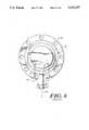
- FIG. 4is a bottom view of the prior art implantable device of FIG. 3;
- FIG. 5is a perspective view of an alternative embodiment of the present invention adapted for coupling a dual lumen catheter to a dual lumen fluid transfer device;
- FIG. 6is a cross-sectional view of an alternative embodiment of the invention installed over a catheter fitted over a fluid access port, but before being mated with a cooperating twist-locking receiver of a fluid transfer device;
- FIG. 7is a cross-sectional view of the connector embodiment of FIG. 6 and a partial view of a fluid transfer device after the connector is mated with the twist-locking receiver of the fluid transfer device;
- FIG. 8is a perspective view of an additional embodiment of the invention.
- FIG. 9is a cross-sectional view of the embodiment of FIG. 8;
- FIG. 10is a cross-sectional view of an embodiment of the invention similar to that of FIG. 8 but with a different sleeve configuration
- FIG. 11is a cross-sectional view of another sleeve configuration suitable for use in the general configuration of FIG. 8;
- FIG. 12is a cross-sectional view of the connector embodiment of FIG. 10 installed over a catheter fitted over a fluid access port after being mated with a cooperating twist-locking receiver of a fluid transfer device;
- FIGS. 13A through 13Cillustrate the process of moving of the connector of FIG. 12 into a locked relationship with the fluid transfer device
- FIG. 14is a perspective view of an implantable vascular access device having a locking retention member and including a connector locked into place;
- FIGS. 15A, 15B, 16A, 16B, 17A and 17Billustrate the front and side views of an implantable device as in FIG. 14 together with a connector in a sequence of steps for locking the body part to the implantable device.
- FIG. 1is a perspective view of a connector 10 in accordance with the present invention, showing general cooperation of a cylindrical compression sleeve 40 (having an inner diameter D s ) fitted within a body part 50.
- Body part 50is provided with extensions, such as pins or wing elements 54a, 54b, and, along with sleeve 40, generally forms a general T-shaped coupler extending along a central reference axis 12 for coupling with a generally T-shaped coupler receiver of a cooperating fluid transfer device.
- FIG. 2is a top cross-sectional view of connector 10 about to secure the proximal end 29 of a flexible vascular catheter 20 to a tubular fluid port 37 (having an outer diameter d) extending from an implantable vascular access device 30 of the type generally shown in U.S. Pat. No. 4,673,394.
- the distal end (not shown) of catheter 20is positioned at a desired position in the patient's vascular system.
- a cooperating fluid transfer devicetakes the form of an implantable vascular access device 30 as shown in the perspective view of FIG. 3 and the bottom view of FIG. 4.
- Device 30preferably includes a device housing 32 which defines an internal generally cup-shaped reservoir cavity 34, e.g., for holding treatment fluids or medicine.
- Device housing 32has an open face which is closed off by a cover 36.
- Tubular fluid flow or fluid exit (or inlet) port 37extends out radially from wall 35 of device housing 32 along port axis 37a. The interior of port 37 is coupled directly to cavity 34.
- Cover 36is formed of a self-resealing polymer, which is preferably an elastomer such as silicone, rubber or latex, and is adapted to permit access to the reservoir cavity 34 using a hypodermic needle.
- a hypodermic needlemay be employed to puncture cover 36 to deliver a treatment fluid to reservoir cavity 34.
- the treatment fluidis then delivered to catheter 20 coupled to the tubular port 37 (having outer diameter d, where d is less than D s ) of device 30, whereby the fluid is provided to the vascular system of the patient.
- Device 30may alternatively be configured to permit out-flow of body fluids, for example, blood in conjunction with a hemodialysis procedure.
- Device housing 32is preferably formed of a biocompatible material, such as titanium or electro-polished 316 L stainless steel or other surgical grade steel or other hard material such as DuPont DelrinTM or TeflonTM.
- a substantially planar, radially extending flange 38circumscribes housing 32.
- Flange 38includes an array of holes 39 spaced about the perimeter of housing 32, for use in suturing device 30 to a layer of the patient's tissue during the implantation procedure.
- Extension portions 41 of flange 38extend on both sides of port 37.
- Preferably flange 38 and portions 41define a generally T-shaped void region 24 disposed about port 37.
- void region 24comprises an axially extending portion 44 and a circumferentially extending portion 46.
- the axial portion 44has a width D and the circumferential portion 46 has a width D', where D' is greater than D.
- Flange 38 and portions 41 and void region 24thus form a T-shaped twist-locking receiver whose function is further set forth below.
- a leak-free and secure fitis required between the resilient catheter proximal end 29 and the rigid tubular port 37.
- the difficulty of forcing catheter end 29 over tubular port 37requires such cooperation that the catheter end 29 slides onto port 37 with some ease.
- this eased couplingmay not be so tight as to be leak free, or worse, may permit inadvertent disconnection.
- FIG. 5an alternative fluid transfer device 130 and associated catheters 132 and 134 are shown in FIG. 5, together with a connector 10 embodying the invention.
- Device 130includes flanges 138 which define a coupler receiver 143 including a generally T-shaped region as illustrated.
- Device 130is adapted to couple each of catheters 132 and 134, through one of ports 175a and 175b to a respective lumen 173a, 173b of a dual lumen catheter 120 having a proximal end 129.
- Catheter 120includes an internal divider 173 which creates the two lumens 173a, 173b internal to the catheter.
- the two ports 175a and 175b of device 130are separated by a gap 175c, each port being adapted to receive one of the lumens 173a, 173b of catheter 120 for transport of multiple fluids from/to a multiple lumen transfer device 130.
- Gap 175cis so configured as to receive catheter divider 173 as the catheter is fitted over the ports. The need for proper alignment and coupling of the respective catheter lumen and ports 175a and 175b is therefore self-evident. (It will be further appreciated, however, that the present invention applies equally well in use with a single, multiple lumen catheter and like single multiple lumen port.)
- connector device 10 of the present inventionprovides compression sleeve 40 to assure a leak-free and secure fit of the catheter end 29 over port 37 (FIG. 2) or end 129 over ports 175a and 175b (FIG. 5).
- the compression sleeveis substantially rigid relative to the substantially flexible catheter.
- the resilient cathetercan be reasonably sized for tight but comfortable placement over port 37 (or ports 175a and 175b).
- the connector device 10is first positioned so that sleeve 40 extends about end 29 (or 129) of the catheter 20 (or 120) and then this entire assembly is slidingly placed over port 37 (or ports 175a and 175b).
- the cathetercan first be slidingly placed over port 37 (or ports 175a and 175b) without, or with minimal, twisting, and then compression sleeve 40 is slidingly placed over the catheter/port conjunction.
- the rigid sleevesupplies a higher degree of compression between the joined tube and port to assure a leak-free connection that will not easily or inadvertently disconnect.
- Body part 50defines a generally arcuate smooth inner glide surface, i.e., disposed about cylindrical central aperture 56.
- the outer surface of compression sleeve 40defines a generally arcuate smooth glide surface, i.e., an exterior generally cylindrical outer contour 48 configured to cooperate with the body part central aperture 56.
- Sleeve 40further defines a generally arcuate smooth-walled orifice, i.e., a generally cylindrical central aperture 46 for compressive receipt of catheter 20.
- Aperture 46is of an internal diameter which causes compression of the catheter as the sleeve is slid over the surface of the catheter up to and over the catheter/port conjunction 47, as enabled by the resilient character of the catheter material (typically a plastic or elastomer).
- body part 50 at its central aperture 56is fitted over compression sleeve 40 in a closely cooperating manner, thus capturing sleeve 40.
- sleeve 40compressively secures the proximal end 29 of catheter 20 to port 37, the sleeve essentially is fixed in the axial direction relative to the catheter. Therefore, body part 50 at its central aperture 56 must slidingly engage the outer surface 48 of sleeve 40 so that it can be twisted into locking cooperation at receiver 43 of device 30 without causing the sleeve and catheter to be twisted.
- body part 50, as so mounted on sleeve 40may be freely rotated about the relatively fixed sleeve.
- body part 50includes inset grooves 58a, 58b, and sleeve 40 includes raised flanges 48a, 48b, whereby body part 50 is installed over sleeve 40 with flanges 48a, 48b mating with grooves 58a, 58b, respectively.
- sleeve 40is prevented from slipping away from its location over catheter 20 and catheter/port conjunction 47, while body part 50 can still be rotated about sleeve 40 during such mating.
- This groove/flange combinationpermits body part 50 to be forced over sleeve 40 after the latter has been fitted into its desired compression location over the catheter/port conjunction 47.
- connector 10In an alternative embodiment of connector 10, an example of which is shown in FIG. 6, only a single groove 91a and single flange 91b are provided for interlocking of body part 50 and sleeve 40.
- the locations of the flanges on sleeve 40 and grooves on part 50could be reversed in yet other embodiments. Still other variations by which the sleeve 40 is captively held by body part 50 are also within the scope of the present invention.
- connector 10can tightly secure catheter 20 (120) to port 37 (or ports 175a and 175b) of device 30 (130) against unwanted leakage or disconnection, and the entire connection is secured against unwanted disconnection by means of the T-shaped lock mechanism, without unwanted twisting or torquing of the catheter.
- T-shapedrefers to any reasonable shape having a width on the perimeter of the flange 38 which is smaller than the width at the end of the void region 24 which is distal to the flange perimeter.
- An alternate example of such an openingwould be a dovetail-shaped opening.
- An optional feature of the inventionincludes a confirmation mechanism for indication of correct coupling of connector 10 and the fluid delivery device.
- the mechanismmay include a contact spot or protrusion 55 on connector body part 50 and a cooperating contact spot or lip 155 of the flange of the fluid delivery device.
- a "tactile" or “click”-type indication of correct placementcan be felt by the surgeon as the body part wing elements 54a, 54b are properly seated in the receiver of the fluid delivery device.
- contact devices 55, 155are designed to interact only when the T-shaped connector is properly locked in secure and mating cooperation in the T-shaped receiver of the delivery device.
- a securing device 62is provided on connector 10 to prevent inadvertent detachment of the connector from the delivery device.
- Securing device 62may include a flange 62a which is an extension of body part 50.
- Flange 62ainternally defines a tie down hole 62b. Tie down hole 62b permits suturing the body part perhaps to one of the plurality of holes 39 in flange 38 of device 30, for example, after connector 10 is properly connected to device 30.
- sleeve 40over catheter/port conjunction 47 requires selection of a sleeve with an inner diameter greater than the outer diameter of the port and less than the outer diameter of the catheter after the catheter is installed on tube 37. This normally assures adequate compression of the catheter.
- insert 80provides for tight coupling of the catheter/port conjunction 47.
- insert 80is a generally cylindrical sleeve, which in cross-section, as shown in FIG. 6, is generally wedge-shaped, and is formed from a material which is compressible between device 30 and connector 10.
- the insertdefines an outer surface 81, an abutment surface 82, an inner surface 83, and an insertion end 89.
- sleeve 40is preferably provided with an inclined edge 97 which defines a tapered annular entryway for receipt of cooperatively tapered surface 81 of insert 80.
- insert 80provides an extra degree of leak-free compressive sealing between catheter 20 and device 30.
- connector 10is first placed over catheter 20 to overlie the catheter end 29. Then the compressible insert 80 is placed over end 29 of catheter 20. Now insert 80 and catheter 20 together with connector 10 (sleeve 40 and body part 50) are slid over port 37, with the catheter end 29 extending up toward wall 35 of device 30. The body part 50 of connector 10 is then twist-lock coupled with device 30. The action of forcing connector 10 into locked interconnection with device 30 forces compression surfaces 81, 83 between sleeve 40 and catheter 20 and forces a portion of insert 80 between wall 35 and faces 50' of body part 50 and 20' of catheter 20 to further seal the catheter's connection to device 30.
- insert 80may be formed as a split ring of a material similar to that of sleeve 40, having an inner diameter greater than the catheter inner diameter and less than the catheter outer diameter.
- the split face 80x of a split insert 80is shown in FIG. 7.
- device 30is intended to be sutured directly to the patient, a high degree of maneuverability of device 30 and accessibility of suture holes 39 is desired to facilitate the surgical process of implantation. Additionally, because device 30 connects directly, via catheter 20, to the patient's vascular system, the integrity of the connection between the catheter and the device must be assured. Moreover, in order to reduce risk of harm to the patient, it is preferred that the catheter be moved minimally during and after placement of the catheter distal end within the vascular system.
- the sleeve and body partneed not be formed from biocompatible material if not to be implanted. They may be formed of DuPont DelrinTM (acetal resin), thermoplastic, metal (such as titanium), DuPont TeflonTM (polytetrafluoroethylene), or a mixture of nylon and polyethylene, as their use may dictate.
- the compression sealfor example, may be a split ring formed of the above materials or, as a soft compressible ring, of silicone, polyurethane, butyl rubber, or ethylene propylene.
- FIGS. 8 and 9illustrate an alternative embodiment of connector 10.
- the connector 10includes the outer body part 250 extending along a central reference axis 212 and within which is inserted compression sleeve 240 generally formed with similar features to those of the embodiments illustrated in FIGS. 1 through 5.
- the compression sleeve 240is formed with an outer annular flange face 200 and a rib 291b extending around the sleeve circumference.
- the body piece 250includes a groove 291a positioned to receive the rib 291b when the sleeve has been inserted into a position where the flange 200 is in contact with the face of the body part 250.
- the sleeveis retained within the body part 250 by the action of rib 291b engaging the groove 291a while the flange face 200 abuts the body part 250.
- Thisallows for rotational movement of the sleeve within the body part while not allowing for any significant axial movement.
- the sleeve 240 of FIG. 9is not formed having a single inner diameter bore, but rather the inner diameter of the sleeve in the region 246a, immediately adjacent the flange 200, has a diameter D s1 up to point 217, where the inner diameter in the region 246b has a step decrease to a smaller bore having a diameter D s2 .
- the diameter D s1is selected to be about equal to the expected diameter d of the fluid transfer device tubular extension 37 plus twice the thickness t of the catheter 20 wall when the catheter has been stretched to fit over the tubular extension of the fluid transfer device.
- Diameter D s1can be either an easily sliding fit or a slightly compressive fit.
- the diameter D s2is less than D s1 .
- the length l 1 from the face flange 200 to the point of decreased diameter 217is less than the expected length l 2 of the tubular extension 37 (FIG. 12).
- the rigid body part 250includes wing elements 254a and 254b forming a front flange on the body part to be rotated into an interlocking relationship with the void region of the transfer device as illustrated in FIGS. 13A through 13C.
- a securing element 262 attached to wing elements 254ais approximately centered on the arcuate edge of wing elements 254a, and generally is in abutting relationship with the rear face of that wing.
- Securing element 262provides a convenient lever for rotating the body part 250 to engage the wings with the fluid transfer device voids for interlocking the body part and the fluid transfer device together, as well as a tie down hole 262b for suturing the body part to the fluid transfer device.
- a retention member 201On the opposite side of the body 250, located at approximately 180°, with respect to the securing element 262 is a retention member 201. This extends out from the body part radially a short distance (less than the wing element 254b on the corresponding side) and has a thickness approximately the same as that of the securing element 262. This retention element serves the function of retaining the body part 250 in its engaged locked in, position with respect to the transfer device, after the body part 250 has been rotated into engagement.
- the retention member 201may be formed with a generally quarter round cross section to interact with the beveled lower surface 241 of the receiver extension portion 41, allowing the retention member 201 to slide readily by this portion 41, under clockwise rotation and once past, the flat edge of the retention element 201 provides a positive lock preventing inadvertent body part rotation. The details of this operation will be discussed below.
- FIG. 10there is shown an alternative version of the sleeve 240 of FIGS. 8 and 9.
- the inner diameter of the sleeve 240 at the region 246a near the end of the sleeve 240 near the annular face 200has a diameter D s1 and tapers inwardly from that point continuously until it reaches intermediate point 217 at which the point the inner diameter in the region 246b has decreased to the value D s2 .
- the version shown in FIG. 10is the same as that shown in FIGS. 8 and 9.
- FIG. 11shows an alternative sleeve configuration.
- the reduction from diameter D s1 to diameter D s2is achieved by an internal circumferential rib 245 positioned at point 217, and extending inwardly from the interior wall of the sleeve.
- the rib 245may be continuous or may be formed of discrete separate segments.
- the purpose of the decreasing inner diameters in FIGS. 8, 9, 10 and 11is to improve the sealing at the face of the transfer assembly when the connector 10 is engaged therewith.
- the decreased portion of the sleeve borereaches that portion of the catheter 20 which is now fitted over the tubular extension 37, it does not continue to slide as before, but rather, because of the decrease in diameter, engages the wall of the catheter 20 closely enough to move it forward toward the abutting contact area of the transfer assembly. As illustrated most completely in FIG.
- thiscauses a portion 220 of the catheter wall 20 to be bunched up and compressed between the annular face flange 200 of the sleeve 240 and the contact face 235 of a fluid transfer device 230 (similar to transfer device 130 shown in FIG. 5), resulting in the formation of an annular compressed ring 220 of the catheter wall thereby establishing a firm seal at that contact face.
- a fluid transfer device 230similar to transfer device 130 shown in FIG. 5
- another feature of this embodimentis the inclusion of a retention member 201 on the body part 250.
- the radial extension of the retention member 201 from body part 250is less than the radial extension of the adjacent wing element 254b and has a ramp shaped surface 201a. Accordingly, as illustrated in FIG. 13A through FIG. 13C, when the connector is rotated into engagement, with the elements defining the void regions of receiver 243 of the fluid transfer device 230, this retention member 201 can be forced past the projection portion 241 of the flange 238 of the transfer device such that it snaps into a position on the same face of the flange 238 as securing member 262 occupies with respect to the other portion 241 of the transfer device flange 238. This provides that, when in the engaged position, the connector 10 cannot be rotated out of the engaged position without the specific effort of passing this retention member 201 back past that flange portion 41.
- FIGS. 14, 15, 15B, 16A, 16B, 17A, and 17Billustrate an embodiment in which a retention element 360 for locking the connector body 350 to the vascular implantable access device 330 is located on the wall 332 of the implantable device.
- the retention element 360interlocks with a wing element 362 on the connector body when the connector is in the engaged position.
- a sealis established between catheter the 320 and the contact face 335 of device 330.
- device 330has a cover 336.
- FIG. 14an implantable vascular access device 330 generally as shown in FIG. 3 is shown in an interlocked position with connector body 350.
- Flange 338 of device 330includes an array of holes 339 for use in suturing device 330 to a layer of the patient's tissue.
- a ramp shaped retention element 360is positioned on the wall 332 of the device 330.
- the wing element 362 of connector body 350has been rotated past this retention element 360 and snapped into place in a horizontal position. This interlocks the connector 350 and the implantable device 330 to maintain the connector in the engaged position.
- step 1the connector body part is pushed over the tubular port (not shown) of the implantable device with wing element 362 in a vertical position.
- the wing element 362is rotated clockwise to engage the ramp face of retention member 360, thereby also rotating flange 354b into the T-shaped slot 355 formed by the portions 341 of flange 338.
- FIGS. 17A and 17Bthe body 350 of the connector is fully rotated, moving wing element 362 beyond the ramp edge of retention element 360, locking the connector body 350 to the implantable device 330, with flanges 354a and 354b held in the T-shaped slot 355.
Landscapes
- Health & Medical Sciences (AREA)
- Heart & Thoracic Surgery (AREA)
- Animal Behavior & Ethology (AREA)
- General Health & Medical Sciences (AREA)
- Anesthesiology (AREA)
- Biomedical Technology (AREA)
- Hematology (AREA)
- Life Sciences & Earth Sciences (AREA)
- Pulmonology (AREA)
- Engineering & Computer Science (AREA)
- Public Health (AREA)
- Veterinary Medicine (AREA)
- Infusion, Injection, And Reservoir Apparatuses (AREA)
- Ultra Sonic Daignosis Equipment (AREA)
- Surgical Instruments (AREA)
- Formation And Processing Of Food Products (AREA)
- Media Introduction/Drainage Providing Device (AREA)
Abstract
Description
Claims (13)
Priority Applications (1)
| Application Number | Priority Date | Filing Date | Title |
|---|---|---|---|
| US07/894,823US5312337A (en) | 1990-10-10 | 1992-06-08 | Catheter attachment device |
Applications Claiming Priority (2)
| Application Number | Priority Date | Filing Date | Title |
|---|---|---|---|
| US07/595,172US5129891A (en) | 1989-05-19 | 1990-10-10 | Catheter attachment device |
| US07/894,823US5312337A (en) | 1990-10-10 | 1992-06-08 | Catheter attachment device |
Related Parent Applications (1)
| Application Number | Title | Priority Date | Filing Date |
|---|---|---|---|
| US07/595,172Continuation-In-PartUS5129891A (en) | 1989-05-19 | 1990-10-10 | Catheter attachment device |
Publications (1)
| Publication Number | Publication Date |
|---|---|
| US5312337Atrue US5312337A (en) | 1994-05-17 |
Family
ID=24382052
Family Applications (2)
| Application Number | Title | Priority Date | Filing Date |
|---|---|---|---|
| US07/595,172Expired - LifetimeUS5129891A (en) | 1989-05-19 | 1990-10-10 | Catheter attachment device |
| US07/894,823Expired - LifetimeUS5312337A (en) | 1990-10-10 | 1992-06-08 | Catheter attachment device |
Family Applications Before (1)
| Application Number | Title | Priority Date | Filing Date |
|---|---|---|---|
| US07/595,172Expired - LifetimeUS5129891A (en) | 1989-05-19 | 1990-10-10 | Catheter attachment device |
Country Status (11)
| Country | Link |
|---|---|
| US (2) | US5129891A (en) |
| EP (1) | EP0553254B1 (en) |
| JP (1) | JPH0781662B2 (en) |
| AT (1) | ATE146577T1 (en) |
| AU (1) | AU655611B2 (en) |
| CA (1) | CA2091568C (en) |
| DE (2) | DE69123752T2 (en) |
| DK (1) | DK0553254T3 (en) |
| ES (1) | ES2094826T3 (en) |
| GR (1) | GR3022422T3 (en) |
| WO (1) | WO1992007215A1 (en) |
Cited By (152)
| Publication number | Priority date | Publication date | Assignee | Title |
|---|---|---|---|---|
| US5387192A (en)* | 1994-01-24 | 1995-02-07 | Sims Deltec, Inc. | Hybrid portal and method |
| US5534221A (en)* | 1992-03-13 | 1996-07-09 | American Sterilizer Company | Device and system for sterilizing objects |
| US5562618A (en)* | 1994-01-21 | 1996-10-08 | Sims Deltec, Inc. | Portal assembly and catheter connector |
| US5601540A (en)* | 1995-07-14 | 1997-02-11 | Stevens; Brian | Apparatus for positioning a split ring over an enlarged flange |
| US5637102A (en)* | 1995-05-24 | 1997-06-10 | C. R. Bard, Inc. | Dual-type catheter connection system |
| US5637088A (en)* | 1995-09-14 | 1997-06-10 | Wenner; Donald E. | System for preventing needle displacement in subcutaneous venous access ports |
| US5672158A (en)* | 1992-01-07 | 1997-09-30 | Sherwood Medical Company | Catheter introducer |
| US5674201A (en)* | 1995-03-16 | 1997-10-07 | Becton Dickinson And Company | Rotatable catheter housed within a flexible wing assembly |
| US5772261A (en)* | 1995-07-21 | 1998-06-30 | The Nemours Foundation | Cannula connector and method of connecting medical tubes |
| US5885217A (en)* | 1995-01-20 | 1999-03-23 | Tyco Group S.A.R.L. | Catheter introducer |
| US5913852A (en)* | 1995-07-21 | 1999-06-22 | Nemours Foundation | Drain cannula |
| US5989216A (en)* | 1995-06-29 | 1999-11-23 | Sims Deltec, Inc. | Access portal and method |
| US5989240A (en)* | 1998-02-27 | 1999-11-23 | Becton, Dickson And Company | Adaptor for mounting a fluid handling device on a catheter tubing |
| US6113572A (en)* | 1995-05-24 | 2000-09-05 | C. R. Bard, Inc. | Multiple-type catheter connection systems |
| US6287281B1 (en) | 1998-07-02 | 2001-09-11 | Scimed Life Systems, Inc. | Low profile retention system |
| US6485461B1 (en) | 2000-04-04 | 2002-11-26 | Insulet, Inc. | Disposable infusion device |
| US6607504B2 (en) | 2001-06-29 | 2003-08-19 | Scimed Life Systems, Inc. | Percutaneous access |
| US6632194B1 (en)* | 1999-11-17 | 2003-10-14 | W.O.M. World Of Medicine Gmbh | Device for insufflating gas |
| US20030199853A1 (en)* | 2002-04-23 | 2003-10-23 | Medtronic Inc. | Implantable medical connector for medical tubing with anchoring features |
| US6638242B2 (en) | 2001-01-24 | 2003-10-28 | Jon S. Wilson | Multi-lumen catheter with attachable hub |
| US6656158B2 (en) | 2002-04-23 | 2003-12-02 | Insulet Corporation | Dispenser for patient infusion device |
| US6656159B2 (en) | 2002-04-23 | 2003-12-02 | Insulet Corporation | Dispenser for patient infusion device |
| US6669669B2 (en) | 2001-10-12 | 2003-12-30 | Insulet Corporation | Laminated patient infusion device |
| US20040002693A1 (en)* | 2002-06-26 | 2004-01-01 | Bright Jeffrey D. | Implantable pump connector for catheter attachment |
| US20040015131A1 (en)* | 2002-07-16 | 2004-01-22 | Flaherty J. Christopher | Flow restriction system and method for patient infusion device |
| US20040027083A1 (en)* | 2002-04-26 | 2004-02-12 | Toyoda Koki Kabushiki Kaisha | Motor control device |
| US6692457B2 (en) | 2002-03-01 | 2004-02-17 | Insulet Corporation | Flow condition sensor assembly for patient infusion device |
| US6699218B2 (en) | 2000-11-09 | 2004-03-02 | Insulet Corporation | Transcutaneous delivery means |
| US20040064088A1 (en)* | 2002-09-30 | 2004-04-01 | William Gorman | Dispenser components and methods for patient infusion device |
| US20040064096A1 (en)* | 2002-09-30 | 2004-04-01 | Flaherty J. Christopher | Components and methods for patient infusion device |
| US20040068233A1 (en)* | 2002-10-04 | 2004-04-08 | Dimatteo Kristian | Venous access device with detachable suture wings |
| US6723072B2 (en) | 2002-06-06 | 2004-04-20 | Insulet Corporation | Plunger assembly for patient infusion device |
| US20040078004A1 (en)* | 2002-10-21 | 2004-04-22 | George Bourne | Implantable medical device for improved placement and adherence in the body |
| US20040078028A1 (en)* | 2001-11-09 | 2004-04-22 | Flaherty J. Christopher | Plunger assembly for patient infusion device |
| WO2004034940A1 (en)* | 2002-10-18 | 2004-04-29 | Radiant Medical, Inc. | Valved connector assembly and sterility barriers for heat exchange catheters and other closed loop catheters |
| US20040087894A1 (en)* | 2000-09-08 | 2004-05-06 | Flaherty J. Christopher | Devices, systems and methods for patient infusion |
| US6749587B2 (en) | 2001-02-22 | 2004-06-15 | Insulet Corporation | Modular infusion device and method |
| US20040116866A1 (en)* | 2002-12-17 | 2004-06-17 | William Gorman | Skin attachment apparatus and method for patient infusion device |
| US6768425B2 (en) | 2000-12-21 | 2004-07-27 | Insulet Corporation | Medical apparatus remote control and method |
| US20040152530A1 (en)* | 2003-01-23 | 2004-08-05 | Daley Richard A. | Golf putting device |
| US20040153032A1 (en)* | 2002-04-23 | 2004-08-05 | Garribotto John T. | Dispenser for patient infusion device |
| US20040172003A1 (en)* | 2001-01-24 | 2004-09-02 | Wilson Jon S. | Method of inserting double-Y-shaped catheter with attachable hubs |
| US20040220643A1 (en)* | 2001-04-27 | 2004-11-04 | Medtronic, Inc. | Implantable medical device with rechargeable thin-film microbattery power source |
| US20040243057A1 (en)* | 2001-10-25 | 2004-12-02 | Jakob Vinten-Johansen | Catheter for modified perfusion |
| US6830558B2 (en) | 2002-03-01 | 2004-12-14 | Insulet Corporation | Flow condition sensor assembly for patient infusion device |
| US20050065760A1 (en)* | 2003-09-23 | 2005-03-24 | Robert Murtfeldt | Method for advising patients concerning doses of insulin |
| US20050070847A1 (en)* | 2003-09-29 | 2005-03-31 | Van Erp Wilhelmus Petrus Martinus Maria | Rapid-exchange balloon catheter with hypotube shaft |
| US20050124980A1 (en)* | 2003-12-03 | 2005-06-09 | Sanders Scott W. | Port stem marking for catheter placement |
| US20050148955A1 (en)* | 2003-12-26 | 2005-07-07 | Medtronic Minimed, Inc. | Modular catheter system |
| US6921396B1 (en) | 2002-08-30 | 2005-07-26 | Arrow International, Inc. | Multi-lumen catheter with integrated connector |
| US20050182366A1 (en)* | 2003-04-18 | 2005-08-18 | Insulet Corporation | Method For Visual Output Verification |
| US20050187578A1 (en)* | 2002-09-20 | 2005-08-25 | Rosenberg Michael S. | Temporary retention device |
| US20050209581A1 (en)* | 2004-03-18 | 2005-09-22 | Butts M D | Catheter connector |
| US20050209583A1 (en)* | 2004-03-18 | 2005-09-22 | Powers Kelly B | Connector system for a proximally trimmable catheter |
| US20050215960A1 (en)* | 2004-03-24 | 2005-09-29 | Mark Girard | Dual lumen port with F-shaped connector |
| US20050238507A1 (en)* | 2002-04-23 | 2005-10-27 | Insulet Corporation | Fluid delivery device |
| US6960192B1 (en) | 2002-04-23 | 2005-11-01 | Insulet Corporation | Transcutaneous fluid delivery system |
| US20050253389A1 (en)* | 2004-05-13 | 2005-11-17 | Schulte Gregory T | Medical tubing connector assembly incorporating strain relief sleeve |
| US20050277862A1 (en)* | 2004-06-09 | 2005-12-15 | Anand Pj | Splitable tip catheter with bioresorbable adhesive |
| US20060015086A1 (en)* | 2004-04-01 | 2006-01-19 | Kelly Rasmussen | Catheter connector system |
| US20060116648A1 (en)* | 2004-07-26 | 2006-06-01 | Bret Hamatake | Port design and method of assembly |
| US20060142699A1 (en)* | 2004-12-23 | 2006-06-29 | Lampropoulos Fred P | Rotatable suture ring |
| US20060178648A1 (en)* | 2004-12-14 | 2006-08-10 | C. R. Bard, Inc. | Fast clear port |
| US20060178633A1 (en)* | 2005-02-03 | 2006-08-10 | Insulet Corporation | Chassis for fluid delivery device |
| US7128734B1 (en) | 2002-09-20 | 2006-10-31 | Arrow International, Inc. | Apparatus and method for reverse tunneling a multi-lumen catheter in a patient |
| US20060264911A1 (en)* | 2005-05-20 | 2006-11-23 | Medtronic, Inc. | Squeeze-actuated catheter connector and method |
| US20060264814A1 (en)* | 2005-05-20 | 2006-11-23 | Medtronic, Inc. | Locking catheter connector and method |
| US20060288125A1 (en)* | 2005-05-23 | 2006-12-21 | Boyd William T | System and method for user space operations for direct I/O between an application instance and an I/O adapter |
| US20070167931A1 (en)* | 2005-12-29 | 2007-07-19 | Wilson-Cook Medical Inc. | Catheter connector assemblies and methods for attaching a catheter and luer assembly |
| US20070225651A1 (en)* | 2006-03-09 | 2007-09-27 | Rosenberg Michael S | Anchor device and method |
| US7300430B2 (en) | 2001-01-24 | 2007-11-27 | Arrow International, Inc. | Multi-lumen catheter with attachable hub |
| US20080009832A1 (en)* | 2005-06-20 | 2008-01-10 | C. R. Bard, Inc. | Connection system for multi-lumen catheter |
| US20080097385A1 (en)* | 2004-12-22 | 2008-04-24 | Jakob Vinten-Johansen | Therapeutic Adjuncts to Enhance the Organ Protective Effects of Postconditioning |
| US20080097296A1 (en)* | 2006-08-16 | 2008-04-24 | Boston Scientific Scimed, Inc. | Removable hub assembly for medical device |
| US20080312599A1 (en)* | 2007-06-15 | 2008-12-18 | Interrad Medical, Inc. | Anchor instrumentation and methods |
| US20090030492A1 (en)* | 2007-07-27 | 2009-01-29 | Cyberonics, Inc. | Nerve lead tie down with bearing |
| US20090118701A1 (en)* | 2003-05-27 | 2009-05-07 | Spire Corporation | Methods and apparatus for inserting multi-lumen split-tip catheters into a blood vessel |
| US7537245B2 (en) | 2005-02-14 | 2009-05-26 | Medtronic, Inc. | Strain relief device and connector assemblies incorporating same |
| US20090204079A1 (en)* | 2007-10-17 | 2009-08-13 | Spire Corporation | Catheters with enlarged arterial lumens |
| US20090204052A1 (en)* | 2007-10-17 | 2009-08-13 | Spire Corporation | Manufacture of split tip catheters |
| US20090204072A1 (en)* | 2005-03-04 | 2009-08-13 | C. R. Bard, Inc. | Access port identification systems and methods |
| US20090209940A1 (en)* | 2008-02-15 | 2009-08-20 | Spire Corporation | Fusion manufacture of multi-lumen catheters |
| US20090205189A1 (en)* | 2008-02-15 | 2009-08-20 | Spire Corporation | Manufacture of fixed tip catheters |
| US20090270809A1 (en)* | 2008-03-28 | 2009-10-29 | Innovamedica S.A.P.I. De C.V. | Device and method for connecting a blood pump without trapping air bubbles |
| US20090281503A1 (en)* | 2004-10-29 | 2009-11-12 | Merit Medical Systems, Inc. | Self-Suturing Anchor Device |
| US20090326473A1 (en)* | 2008-06-27 | 2009-12-31 | Interrad Medical, Inc. | System for anchoring medical devices |
| US20100063451A1 (en)* | 2008-09-09 | 2010-03-11 | Jeff Gray | Power Injectable Port Identification |
| US20100121313A1 (en)* | 2008-11-13 | 2010-05-13 | Cook Vascular Incorporated | Catheter locking mechanism |
| US20100204656A1 (en)* | 2009-02-06 | 2010-08-12 | Interrad Medical, Inc. | System for anchoring medical devices |
| US7785302B2 (en) | 2005-03-04 | 2010-08-31 | C. R. Bard, Inc. | Access port identification systems and methods |
| US7854731B2 (en) | 2004-03-18 | 2010-12-21 | C. R. Bard, Inc. | Valved catheter |
| US20110177975A1 (en)* | 1996-02-09 | 2011-07-21 | Cornell Research Foundation, Inc. | Detection of nucleic acid sequence differences using the ligase detection reaction with addressable arrays |
| US20110208132A1 (en)* | 2010-02-23 | 2011-08-25 | Smiths Medical Asd, Inc. | Catheter adapter |
| US8025639B2 (en) | 2005-04-27 | 2011-09-27 | C. R. Bard, Inc. | Methods of power injecting a fluid through an access port |
| US8029482B2 (en) | 2005-03-04 | 2011-10-04 | C. R. Bard, Inc. | Systems and methods for radiographically identifying an access port |
| US8038653B2 (en) | 2008-07-16 | 2011-10-18 | Interrad Medical, Inc. | Anchor systems and methods |
| US20110270187A1 (en)* | 2010-04-28 | 2011-11-03 | Nelson Brian D | Body portal anchors and systems |
| US8083728B2 (en) | 2004-03-18 | 2011-12-27 | C. R. Bard, Inc. | Multifunction adaptor for an open-ended catheter |
| US8092415B2 (en) | 2007-11-01 | 2012-01-10 | C. R. Bard, Inc. | Catheter assembly including triple lumen tip |
| US8177762B2 (en) | 1998-12-07 | 2012-05-15 | C. R. Bard, Inc. | Septum including at least one identifiable feature, access ports including same, and related methods |
| USD661388S1 (en) | 2010-02-23 | 2012-06-05 | Smiths Medical Asd, Inc. | Catheter adapter |
| US8202259B2 (en) | 2005-03-04 | 2012-06-19 | C. R. Bard, Inc. | Systems and methods for identifying an access port |
| US8257325B2 (en) | 2007-06-20 | 2012-09-04 | Medical Components, Inc. | Venous access port with molded and/or radiopaque indicia |
| US8292841B2 (en) | 2007-10-26 | 2012-10-23 | C. R. Bard, Inc. | Solid-body catheter including lateral distal openings |
| US20120271280A1 (en)* | 2009-07-23 | 2012-10-25 | Mediplus Limited | Catheter |
| US8337484B2 (en) | 2009-06-26 | 2012-12-25 | C. R. Band, Inc. | Proximally trimmable catheter including pre-attached bifurcation and related methods |
| US8343108B2 (en) | 2010-09-29 | 2013-01-01 | Interrad Medical, Inc. | Systems and methods for anchoring medical devices |
| US8366687B2 (en) | 2004-01-06 | 2013-02-05 | Angio Dynamics | Injection access port with chamfered top hat septum design |
| USD676955S1 (en) | 2010-12-30 | 2013-02-26 | C. R. Bard, Inc. | Implantable access port |
| USD682416S1 (en) | 2010-12-30 | 2013-05-14 | C. R. Bard, Inc. | Implantable access port |
| US8641676B2 (en) | 2005-04-27 | 2014-02-04 | C. R. Bard, Inc. | Infusion apparatuses and methods of use |
| US8696614B2 (en) | 2007-10-26 | 2014-04-15 | C. R. Bard, Inc. | Split-tip catheter including lateral distal openings |
| US8715244B2 (en) | 2009-07-07 | 2014-05-06 | C. R. Bard, Inc. | Extensible internal bolster for a medical device |
| US8808227B2 (en) | 2003-02-21 | 2014-08-19 | C. R. Bard, Inc. | Multi-lumen catheter with separate distal tips |
| AU2012211394B2 (en)* | 2011-08-23 | 2014-09-18 | Ethicon Endo-Surgery, Inc. | Implantable medical port with alignment feature |
| US8932271B2 (en) | 2008-11-13 | 2015-01-13 | C. R. Bard, Inc. | Implantable medical devices including septum-based indicators |
| US8932263B2 (en) | 2012-02-17 | 2015-01-13 | Interrad Medical, Inc. | Anchoring an intravenous cannula |
| US8936576B2 (en) | 2011-09-15 | 2015-01-20 | Interrad Medical, Inc. | System for anchoring medical devices |
| US20150119708A1 (en)* | 2012-01-18 | 2015-04-30 | University Of Utah Research Foundation | Devices and systems for fluorescence imaging of tissue |
| US9079004B2 (en) | 2009-11-17 | 2015-07-14 | C. R. Bard, Inc. | Overmolded access port including anchoring and identification features |
| WO2012106161A3 (en)* | 2011-01-31 | 2015-07-30 | Navilyst Medical, Inc. | Medical device and packaging interface |
| USD748252S1 (en) | 2013-02-08 | 2016-01-26 | C. R. Bard, Inc. | Multi-lumen catheter tip |
| US9265912B2 (en) | 2006-11-08 | 2016-02-23 | C. R. Bard, Inc. | Indicia informative of characteristics of insertable medical devices |
| US9314596B2 (en) | 2012-10-11 | 2016-04-19 | Interrad Medical, Inc. | Systems and methods for anchoring medical devices |
| US9364651B2 (en) | 2010-02-23 | 2016-06-14 | Smiths Medical Asd, Inc. | Adapter with special fitting |
| US9381321B2 (en) | 2013-05-03 | 2016-07-05 | Interrad Medical, Inc. | Systems and methods for anchoring medical devices |
| US9415190B2 (en) | 2013-02-13 | 2016-08-16 | Interrad Medical, Inc. | Systems and methods for anchoring medical devices |
| US9474888B2 (en) | 2005-03-04 | 2016-10-25 | C. R. Bard, Inc. | Implantable access port including a sandwiched radiopaque insert |
| US9517329B2 (en) | 2007-07-19 | 2016-12-13 | Medical Components, Inc. | Venous access port assembly with X-ray discernable indicia |
| US9550043B2 (en) | 2012-12-13 | 2017-01-24 | Interrad Medical, Inc. | Systems and methods for anchoring medical devices |
| US9579485B2 (en) | 2007-11-01 | 2017-02-28 | C. R. Bard, Inc. | Catheter assembly including a multi-lumen configuration |
| US9579496B2 (en) | 2007-11-07 | 2017-02-28 | C. R. Bard, Inc. | Radiopaque and septum-based indicators for a multi-lumen implantable port |
| US9610432B2 (en) | 2007-07-19 | 2017-04-04 | Innovative Medical Devices, Llc | Venous access port assembly with X-ray discernable indicia |
| US9642986B2 (en) | 2006-11-08 | 2017-05-09 | C. R. Bard, Inc. | Resource information key for an insertable medical device |
| US9707339B2 (en) | 2012-03-28 | 2017-07-18 | Angiodynamics, Inc. | High flow rate dual reservoir port system |
| US9713704B2 (en) | 2012-03-29 | 2017-07-25 | Bradley D. Chartrand | Port reservoir cleaning system and method |
| US10166321B2 (en) | 2014-01-09 | 2019-01-01 | Angiodynamics, Inc. | High-flow port and infusion needle systems |
| US10258768B2 (en) | 2014-07-14 | 2019-04-16 | C. R. Bard, Inc. | Apparatuses, systems, and methods for inserting catheters having enhanced stiffening and guiding features |
| US10307581B2 (en) | 2005-04-27 | 2019-06-04 | C. R. Bard, Inc. | Reinforced septum for an implantable medical device |
| US10737087B2 (en) | 2012-04-17 | 2020-08-11 | Smiths Medical Asd, Inc. | Filling fitting |
| US10792484B2 (en) | 2015-10-06 | 2020-10-06 | Praxis Powder Technology, Inc. | Vascular access ports and processes for their manufacture |
| US10898656B2 (en) | 2017-09-26 | 2021-01-26 | Insulet Corporation | Needle mechanism module for drug delivery device |
| US11045603B2 (en) | 2017-02-22 | 2021-06-29 | Insulet Corporation | Needle insertion mechanisms for drug containers |
| US11090434B2 (en) | 2015-11-24 | 2021-08-17 | Insulet Corporation | Automated drug delivery system |
| US11147931B2 (en) | 2017-11-17 | 2021-10-19 | Insulet Corporation | Drug delivery device with air and backflow elimination |
| US11364341B2 (en) | 2015-11-25 | 2022-06-21 | Insulet Corporation | Wearable medication delivery device |
| US11471647B2 (en) | 2014-11-07 | 2022-10-18 | C. R. Bard, Inc. | Connection system for tunneled catheters |
| WO2023033821A1 (en)* | 2021-09-01 | 2023-03-09 | Bard Peripheral Vascular, Inc. | Mechanical clamshell cathlock |
| US11684713B2 (en) | 2012-03-30 | 2023-06-27 | Insulet Corporation | Fluid delivery device, transcutaneous access tool and insertion mechanism for use therewith |
| US11890443B2 (en) | 2008-11-13 | 2024-02-06 | C. R. Bard, Inc. | Implantable medical devices including septum-based indicators |
| US11896782B2 (en) | 2017-08-23 | 2024-02-13 | C. R. Bard, Inc. | Priming and tunneling system for a retrograde catheter assembly |
| US12433512B2 (en) | 2020-12-18 | 2025-10-07 | Insulet Corporation | Adhesive pad with a metallic coil for securing an on-body medical device |
Families Citing this family (46)
| Publication number | Priority date | Publication date | Assignee | Title |
|---|---|---|---|---|
| US5178612A (en)* | 1990-10-10 | 1993-01-12 | Strato Medical Corporation | Compressible split cylinder bayonet locking device for attachment of a catheter to a fluid transfer device |
| US5944697A (en)* | 1994-05-31 | 1999-08-31 | Universal Medical Instrument Corp. | Percutaneous catheter introducer |
| US5792104A (en)* | 1996-12-10 | 1998-08-11 | Medtronic, Inc. | Dual-reservoir vascular access port |
| GB9717821D0 (en) | 1997-08-21 | 1997-10-29 | Spinoza Marc H | Fasteners |
| US6585229B2 (en)* | 1999-01-27 | 2003-07-01 | Nypro Inc. | Medical nozzle securing apparatus |
| US6758836B2 (en) | 2002-02-07 | 2004-07-06 | C. R. Bard, Inc. | Split tip dialysis catheter |
| WO2003070310A1 (en)* | 2002-02-21 | 2003-08-28 | Chul-Jun Kim | Indwelling urinary catheter |
| US20040034333A1 (en)* | 2002-08-19 | 2004-02-19 | Seese Timothy M. | Dialysis catheters with optimized user-friendly connections |
| US7163531B2 (en)* | 2002-08-19 | 2007-01-16 | Baxter International, Inc. | User-friendly catheter connection adapters for optimized connection to multiple lumen catheters |
| US7850660B2 (en)* | 2003-12-19 | 2010-12-14 | Ethicon Endo-Surgery, Inc. | Implantable medical device with simultaneous attachment mechanism and method |
| US8715243B2 (en)* | 2003-06-16 | 2014-05-06 | Ethicon Endo-Surgery, Inc. | Injection port applier with downward force actuation |
| US7862546B2 (en)* | 2003-06-16 | 2011-01-04 | Ethicon Endo-Surgery, Inc. | Subcutaneous self attaching injection port with integral moveable retention members |
| US7561916B2 (en) | 2005-06-24 | 2009-07-14 | Ethicon Endo-Surgery, Inc. | Implantable medical device with indicator |
| US8162897B2 (en)* | 2003-12-19 | 2012-04-24 | Ethicon Endo-Surgery, Inc. | Audible and tactile feedback |
| US8608727B2 (en) | 2004-03-01 | 2013-12-17 | Smiths Medical Asd, Inc. | Delivery system and method |
| DE05770682T1 (en)* | 2004-07-14 | 2007-11-08 | Medical Components, Inc. | ADAPTER FOR CATHETER TUNNELER |
| GB0501750D0 (en)* | 2005-01-27 | 2005-03-02 | Univ College London Hospitals | Drain tube assembly for draining a body cavity |
| WO2007002179A2 (en)* | 2005-06-22 | 2007-01-04 | Wilson-Cook Medical Inc. | Catheter shaft connector |
| US7918844B2 (en) | 2005-06-24 | 2011-04-05 | Ethicon Endo-Surgery, Inc. | Applier for implantable medical device |
| US7651483B2 (en)* | 2005-06-24 | 2010-01-26 | Ethicon Endo-Surgery, Inc. | Injection port |
| GB2429154B (en)* | 2005-07-13 | 2011-06-01 | Sull Ltd | Apparatus for securing a line to a patient |
| US20080114308A1 (en)* | 2006-11-13 | 2008-05-15 | Di Palma Giorgio | Vascular Access Port with Catheter Connector |
| US8574192B2 (en) | 2007-03-02 | 2013-11-05 | Covidien Lp | Catheter tunneling systems, instruments and methods |
| US8430852B2 (en)* | 2007-04-17 | 2013-04-30 | Medtronic, Inc. | Therapeutic sleeve for implantable medical device |
| US20080275401A1 (en)* | 2007-05-01 | 2008-11-06 | Sage Shahn S | Catheter anchor and system/method regarding same |
| US8512312B2 (en) | 2007-05-01 | 2013-08-20 | Medtronic, Inc. | Offset catheter connector, system and method |
| SG174097A1 (en)* | 2007-06-08 | 2011-09-29 | Jms Co Ltd | Male connector |
| US20090112187A1 (en)* | 2007-10-25 | 2009-04-30 | Cook Vascuiar Incorporated | Catheter retention mechanism |
| US20090137944A1 (en)* | 2007-11-27 | 2009-05-28 | Brett Haarala | Medical system and catheter connector apparatus |
| US8262624B2 (en) | 2008-03-27 | 2012-09-11 | Medtronic, Inc. | Anchor and anchor deployment apparatus |
| US8632502B2 (en) | 2008-03-27 | 2014-01-21 | Medtronic, Inc. | Anchor deployment apparatus |
| US8979744B2 (en)* | 2008-09-08 | 2015-03-17 | Covidien Lp | Tunneling system |
| US8708897B2 (en)* | 2008-09-08 | 2014-04-29 | Covidien Lp | Tunneling system |
| GB2464932B (en) | 2008-10-28 | 2013-07-03 | Braidlock Ltd | Methods and apparatus for securing a line |
| US8734426B2 (en) | 2009-10-22 | 2014-05-27 | Cook Medical Technologies Llc | Locking assembly for a drainage catheter |
| WO2011066113A1 (en) | 2009-11-24 | 2011-06-03 | Vance Products Incorporated, D/B/A Cook Urological Incorporated | Locking assembly for a drainage catheter |
| US9248257B2 (en) | 2010-09-30 | 2016-02-02 | Covidien Lp | Tunneler device and method of use |
| US10166365B2 (en) | 2010-09-30 | 2019-01-01 | Covidien Lp | Catheter assembly including sealing member |
| US9782575B2 (en)* | 2012-12-03 | 2017-10-10 | Kenneth M. Zinn | Adjustable-length dual-lumen hemodialysis catheter and a method for its use |
| US20140163529A1 (en)* | 2012-12-10 | 2014-06-12 | Indiana University Research & Technology Corporati | Adapter For A Feeding Tube |
| WO2014115566A1 (en)* | 2013-01-28 | 2014-07-31 | テルモ株式会社 | Tube connection structure |
| US20180214680A1 (en)* | 2017-02-01 | 2018-08-02 | Pfm Medical, Inc. | Identification system for injectable access ports |
| JP7058824B2 (en)* | 2018-01-19 | 2022-04-25 | ニプロ株式会社 | Medical connector |
| WO2022245350A1 (en)* | 2021-05-19 | 2022-11-24 | Bard Peripheral Vascular, Inc. | Cathlock coupling tool |
| WO2023038632A1 (en)* | 2021-09-10 | 2023-03-16 | Bard Peripheral Vascular, Inc. | Anti-ingrowth cathlock |
| DE102022125845A1 (en)* | 2022-10-06 | 2024-04-11 | Gea Farm Technologies Gmbh | Hose quick coupling for at least one hose |
Citations (24)
| Publication number | Priority date | Publication date | Assignee | Title |
|---|---|---|---|---|
| BE528494A (en)* | ||||
| US1042098A (en)* | 1909-05-29 | 1912-10-22 | Victor Talking Machine Co | Talking-machine. |
| US1481341A (en)* | 1920-08-09 | 1924-01-22 | Martin C Bersted | Grease-gun hose coupling |
| FR782512A (en)* | 1934-03-02 | 1935-06-06 | Connection system with watertight seal for rubber or similar hoses | |
| US2907591A (en)* | 1957-10-14 | 1959-10-06 | David E Gulick | Hose coupling having bayonet type joining means |
| US3262718A (en)* | 1965-04-14 | 1966-07-26 | Donald A Draudt | Swivel coupling for coupling flexible and rigid tubular members in end to end relationship |
| US3441296A (en)* | 1967-07-03 | 1969-04-29 | Ellsworth D Wilkin | Hose coupling |
| US3585654A (en)* | 1968-09-12 | 1971-06-22 | Alexander J Jacobs | Quick-disconnect pool cleaning apparatus |
| US4033613A (en)* | 1974-07-05 | 1977-07-05 | Pont-A-Mousson S.A. | Locked joint between two pipe elements capable of having an angular deviation with respect to each other |
| US4273272A (en)* | 1979-11-13 | 1981-06-16 | William B. Anderson | Liquid dispenser |
| US4296949A (en)* | 1979-08-06 | 1981-10-27 | Abbott Laboratories | Rotatable connecting device for I.V. administration set |
| US4325571A (en)* | 1980-05-30 | 1982-04-20 | Funderburg John E | Tube union and method for forming a joint between adjacent end portions of malleable tubing |
| US4625998A (en)* | 1984-04-02 | 1986-12-02 | Draudt Donald A | Swivel hose couplings |
| US4673394A (en)* | 1986-01-17 | 1987-06-16 | Strato Medical Corporation | Implantable treatment reservoir |
| US4735442A (en)* | 1985-09-13 | 1988-04-05 | J. & R. Gunzenhauser Ag | Plastic pipe connection |
| US4834719A (en)* | 1986-04-28 | 1989-05-30 | Cordis Corporation | Quick connect/disconnect tubing adapter |
| US4929243A (en)* | 1988-02-09 | 1990-05-29 | B. Braun Melsungen Ag | Catheter coupling |
| US4929236A (en)* | 1988-05-26 | 1990-05-29 | Shiley Infusaid, Inc. | Snap-lock fitting catheter for an implantable device |
| US4963133A (en)* | 1987-12-31 | 1990-10-16 | Pharmacia Deltec, Inc. | Catheter attachment system |
| US4969879A (en)* | 1988-07-26 | 1990-11-13 | Gish Biomedical, Inc. | Body fluid interconnect |
| US4994048A (en)* | 1988-09-19 | 1991-02-19 | Becton, Dickinson And Company | Apparatus and method for connecting a passageway and openings with a connector |
| US5041098A (en)* | 1989-05-19 | 1991-08-20 | Strato Medical Corporation | Vascular access system for extracorporeal treatment of blood |
| US5045060A (en)* | 1989-04-26 | 1991-09-03 | Therex Corp. | Implantable infusion device |
| US5178612A (en)* | 1990-10-10 | 1993-01-12 | Strato Medical Corporation | Compressible split cylinder bayonet locking device for attachment of a catheter to a fluid transfer device |
- 1990
- 1990-10-10USUS07/595,172patent/US5129891A/ennot_activeExpired - Lifetime
- 1991
- 1991-09-13WOPCT/US1991/006484patent/WO1992007215A1/enactiveIP Right Grant
- 1991-09-13CACA002091568Apatent/CA2091568C/ennot_activeExpired - Fee Related
- 1991-09-13EPEP91919777Apatent/EP0553254B1/ennot_activeExpired - Lifetime
- 1991-09-13DEDE69123752Tpatent/DE69123752T2/ennot_activeExpired - Fee Related
- 1991-09-13AUAU89252/91Apatent/AU655611B2/ennot_activeCeased
- 1991-09-13ATAT91919777Tpatent/ATE146577T1/enactive
- 1991-09-13JPJP3518051Apatent/JPH0781662B2/ennot_activeExpired - Lifetime
- 1991-09-13ESES91919777Tpatent/ES2094826T3/ennot_activeExpired - Lifetime
- 1991-09-13DKDK91919777.2Tpatent/DK0553254T3/enactive
- 1991-09-13DEDE9190145Upatent/DE9190145U1/ennot_activeExpired - Lifetime
- 1992
- 1992-06-08USUS07/894,823patent/US5312337A/ennot_activeExpired - Lifetime
- 1997
- 1997-01-29GRGR970400146Tpatent/GR3022422T3/enunknown
Patent Citations (24)
| Publication number | Priority date | Publication date | Assignee | Title |
|---|---|---|---|---|
| BE528494A (en)* | ||||
| US1042098A (en)* | 1909-05-29 | 1912-10-22 | Victor Talking Machine Co | Talking-machine. |
| US1481341A (en)* | 1920-08-09 | 1924-01-22 | Martin C Bersted | Grease-gun hose coupling |
| FR782512A (en)* | 1934-03-02 | 1935-06-06 | Connection system with watertight seal for rubber or similar hoses | |
| US2907591A (en)* | 1957-10-14 | 1959-10-06 | David E Gulick | Hose coupling having bayonet type joining means |
| US3262718A (en)* | 1965-04-14 | 1966-07-26 | Donald A Draudt | Swivel coupling for coupling flexible and rigid tubular members in end to end relationship |
| US3441296A (en)* | 1967-07-03 | 1969-04-29 | Ellsworth D Wilkin | Hose coupling |
| US3585654A (en)* | 1968-09-12 | 1971-06-22 | Alexander J Jacobs | Quick-disconnect pool cleaning apparatus |
| US4033613A (en)* | 1974-07-05 | 1977-07-05 | Pont-A-Mousson S.A. | Locked joint between two pipe elements capable of having an angular deviation with respect to each other |
| US4296949A (en)* | 1979-08-06 | 1981-10-27 | Abbott Laboratories | Rotatable connecting device for I.V. administration set |
| US4273272A (en)* | 1979-11-13 | 1981-06-16 | William B. Anderson | Liquid dispenser |
| US4325571A (en)* | 1980-05-30 | 1982-04-20 | Funderburg John E | Tube union and method for forming a joint between adjacent end portions of malleable tubing |
| US4625998A (en)* | 1984-04-02 | 1986-12-02 | Draudt Donald A | Swivel hose couplings |
| US4735442A (en)* | 1985-09-13 | 1988-04-05 | J. & R. Gunzenhauser Ag | Plastic pipe connection |
| US4673394A (en)* | 1986-01-17 | 1987-06-16 | Strato Medical Corporation | Implantable treatment reservoir |
| US4834719A (en)* | 1986-04-28 | 1989-05-30 | Cordis Corporation | Quick connect/disconnect tubing adapter |
| US4963133A (en)* | 1987-12-31 | 1990-10-16 | Pharmacia Deltec, Inc. | Catheter attachment system |
| US4929243A (en)* | 1988-02-09 | 1990-05-29 | B. Braun Melsungen Ag | Catheter coupling |
| US4929236A (en)* | 1988-05-26 | 1990-05-29 | Shiley Infusaid, Inc. | Snap-lock fitting catheter for an implantable device |
| US4969879A (en)* | 1988-07-26 | 1990-11-13 | Gish Biomedical, Inc. | Body fluid interconnect |
| US4994048A (en)* | 1988-09-19 | 1991-02-19 | Becton, Dickinson And Company | Apparatus and method for connecting a passageway and openings with a connector |
| US5045060A (en)* | 1989-04-26 | 1991-09-03 | Therex Corp. | Implantable infusion device |
| US5041098A (en)* | 1989-05-19 | 1991-08-20 | Strato Medical Corporation | Vascular access system for extracorporeal treatment of blood |
| US5178612A (en)* | 1990-10-10 | 1993-01-12 | Strato Medical Corporation | Compressible split cylinder bayonet locking device for attachment of a catheter to a fluid transfer device |
Cited By (388)
| Publication number | Priority date | Publication date | Assignee | Title |
|---|---|---|---|---|
| US5672158A (en)* | 1992-01-07 | 1997-09-30 | Sherwood Medical Company | Catheter introducer |
| US5534221A (en)* | 1992-03-13 | 1996-07-09 | American Sterilizer Company | Device and system for sterilizing objects |
| US5562618A (en)* | 1994-01-21 | 1996-10-08 | Sims Deltec, Inc. | Portal assembly and catheter connector |
| US5613945A (en)* | 1994-01-21 | 1997-03-25 | Sims Deltec, Inc. | Portal assembly |
| US5632729A (en)* | 1994-01-21 | 1997-05-27 | Sims Deltec, Inc. | Catheter connector |
| US5743873A (en)* | 1994-01-21 | 1998-04-28 | Sims Deltec, Inc. | Methods for using catheter connectors and portals, and methods of assembly |
| US5558641A (en)* | 1994-01-24 | 1996-09-24 | Sims Deltec, Inc. | Hybrid portal and method |
| US5387192A (en)* | 1994-01-24 | 1995-02-07 | Sims Deltec, Inc. | Hybrid portal and method |
| US5885217A (en)* | 1995-01-20 | 1999-03-23 | Tyco Group S.A.R.L. | Catheter introducer |
| US5674201A (en)* | 1995-03-16 | 1997-10-07 | Becton Dickinson And Company | Rotatable catheter housed within a flexible wing assembly |
| US5637102A (en)* | 1995-05-24 | 1997-06-10 | C. R. Bard, Inc. | Dual-type catheter connection system |
| US6113572A (en)* | 1995-05-24 | 2000-09-05 | C. R. Bard, Inc. | Multiple-type catheter connection systems |
| US5989216A (en)* | 1995-06-29 | 1999-11-23 | Sims Deltec, Inc. | Access portal and method |
| US5601540A (en)* | 1995-07-14 | 1997-02-11 | Stevens; Brian | Apparatus for positioning a split ring over an enlarged flange |
| US5772261A (en)* | 1995-07-21 | 1998-06-30 | The Nemours Foundation | Cannula connector and method of connecting medical tubes |
| US5913852A (en)* | 1995-07-21 | 1999-06-22 | Nemours Foundation | Drain cannula |
| US5637088A (en)* | 1995-09-14 | 1997-06-10 | Wenner; Donald E. | System for preventing needle displacement in subcutaneous venous access ports |
| US20110177975A1 (en)* | 1996-02-09 | 2011-07-21 | Cornell Research Foundation, Inc. | Detection of nucleic acid sequence differences using the ligase detection reaction with addressable arrays |
| US5989240A (en)* | 1998-02-27 | 1999-11-23 | Becton, Dickson And Company | Adaptor for mounting a fluid handling device on a catheter tubing |
| US20040111062A1 (en)* | 1998-07-02 | 2004-06-10 | Srinivas Nishtala | Low profile retention system |
| US7481796B2 (en) | 1998-07-02 | 2009-01-27 | Boston Scientific Scimed, Inc. | Low profile retention system |
| US6287281B1 (en) | 1998-07-02 | 2001-09-11 | Scimed Life Systems, Inc. | Low profile retention system |
| US7854725B2 (en) | 1998-07-02 | 2010-12-21 | Boston Scientific Scimed, Inc. | Low profile retention system |
| US20090093770A1 (en)* | 1998-07-02 | 2009-04-09 | Srinivas Nishtala | Low profile retention system |
| US8177762B2 (en) | 1998-12-07 | 2012-05-15 | C. R. Bard, Inc. | Septum including at least one identifiable feature, access ports including same, and related methods |
| US8608713B2 (en) | 1998-12-07 | 2013-12-17 | C. R. Bard, Inc. | Septum feature for identification of an access port |
| US6632194B1 (en)* | 1999-11-17 | 2003-10-14 | W.O.M. World Of Medicine Gmbh | Device for insufflating gas |
| US6485461B1 (en) | 2000-04-04 | 2002-11-26 | Insulet, Inc. | Disposable infusion device |
| US20040087894A1 (en)* | 2000-09-08 | 2004-05-06 | Flaherty J. Christopher | Devices, systems and methods for patient infusion |
| US7029455B2 (en) | 2000-09-08 | 2006-04-18 | Insulet Corporation | Devices, systems and methods for patient infusion |
| US20050171512A1 (en)* | 2000-09-08 | 2005-08-04 | Insulet Corporation | Devices, systems and methods for patient infusion |
| US7137964B2 (en) | 2000-09-08 | 2006-11-21 | Insulet Corporation | Devices, systems and methods for patient infusion |
| US6699218B2 (en) | 2000-11-09 | 2004-03-02 | Insulet Corporation | Transcutaneous delivery means |
| US6768425B2 (en) | 2000-12-21 | 2004-07-27 | Insulet Corporation | Medical apparatus remote control and method |
| US6872198B1 (en) | 2001-01-24 | 2005-03-29 | Arrow International, Inc. | Double-y-shaped multi-lumen catheter with selectively attachable hubs |
| US7833214B2 (en)* | 2001-01-24 | 2010-11-16 | Arrow International, Inc | Multi-lumen catheter with attachable hub |
| US7300430B2 (en) | 2001-01-24 | 2007-11-27 | Arrow International, Inc. | Multi-lumen catheter with attachable hub |
| US20080033350A1 (en)* | 2001-01-24 | 2008-02-07 | Arrow International, Inc. | Multi-lumen catheter with attachable hub |
| US6638242B2 (en) | 2001-01-24 | 2003-10-28 | Jon S. Wilson | Multi-lumen catheter with attachable hub |
| US7381204B2 (en) | 2001-01-24 | 2008-06-03 | Arrow International, Inc. | Multi-lumen catheter with attachable hub |
| US7749185B2 (en) | 2001-01-24 | 2010-07-06 | Wilson Jon S | Method of inserting double-Y-shaped catheter with attachable hubs |
| US20040065333A1 (en)* | 2001-01-24 | 2004-04-08 | Wilson Jon S. | Multi-lumen catheter with attachable hub |
| US20040171997A1 (en)* | 2001-01-24 | 2004-09-02 | Wilson Jon S. | Double-y-shaped multi-lumen catheter with selectively attachable hubs |
| US20040172003A1 (en)* | 2001-01-24 | 2004-09-02 | Wilson Jon S. | Method of inserting double-Y-shaped catheter with attachable hubs |
| US6749587B2 (en) | 2001-02-22 | 2004-06-15 | Insulet Corporation | Modular infusion device and method |
| US20040220643A1 (en)* | 2001-04-27 | 2004-11-04 | Medtronic, Inc. | Implantable medical device with rechargeable thin-film microbattery power source |
| US6607504B2 (en) | 2001-06-29 | 2003-08-19 | Scimed Life Systems, Inc. | Percutaneous access |
| US20050021005A1 (en)* | 2001-10-12 | 2005-01-27 | Flaherty J. Christopher | Laminated patient infusion device |
| US6669669B2 (en) | 2001-10-12 | 2003-12-30 | Insulet Corporation | Laminated patient infusion device |
| US7686781B2 (en) | 2001-10-25 | 2010-03-30 | Emory University | Catheter for modified perfusion |
| US20040243057A1 (en)* | 2001-10-25 | 2004-12-02 | Jakob Vinten-Johansen | Catheter for modified perfusion |
| US20040078028A1 (en)* | 2001-11-09 | 2004-04-22 | Flaherty J. Christopher | Plunger assembly for patient infusion device |
| US20040092865A1 (en)* | 2001-11-09 | 2004-05-13 | J. Christopher Flaherty | Transcutaneous delivery means |
| US20040127844A1 (en)* | 2002-03-01 | 2004-07-01 | Flaherty J. Christopher | Flow condition sensor assembly for patient infusion device |
| US6692457B2 (en) | 2002-03-01 | 2004-02-17 | Insulet Corporation | Flow condition sensor assembly for patient infusion device |
| US6830558B2 (en) | 2002-03-01 | 2004-12-14 | Insulet Corporation | Flow condition sensor assembly for patient infusion device |
| US7887505B2 (en) | 2002-03-01 | 2011-02-15 | Insulet Corporation | Flow condition sensor assembly for patient infusion device |
| US20030199853A1 (en)* | 2002-04-23 | 2003-10-23 | Medtronic Inc. | Implantable medical connector for medical tubing with anchoring features |
| US7303549B2 (en) | 2002-04-23 | 2007-12-04 | Insulet Corporation | Transcutaneous fluid delivery system |
| US6656159B2 (en) | 2002-04-23 | 2003-12-02 | Insulet Corporation | Dispenser for patient infusion device |
| US20060084940A1 (en)* | 2002-04-23 | 2006-04-20 | Medtronic, Inc. | Implantable medical connector for medical tubing with anchoring features |
| US6656158B2 (en) | 2002-04-23 | 2003-12-02 | Insulet Corporation | Dispenser for patient infusion device |
| US6960192B1 (en) | 2002-04-23 | 2005-11-01 | Insulet Corporation | Transcutaneous fluid delivery system |
| US6997919B2 (en) | 2002-04-23 | 2006-02-14 | Medtronic, Inc. | Implantable medical connector for medical tubing with anchoring features |
| US20050238507A1 (en)* | 2002-04-23 | 2005-10-27 | Insulet Corporation | Fluid delivery device |
| US20060084941A1 (en)* | 2002-04-23 | 2006-04-20 | Medtronic, Inc. | Implantable medical connector for medical tubing with anchoring features |
| US20040153032A1 (en)* | 2002-04-23 | 2004-08-05 | Garribotto John T. | Dispenser for patient infusion device |
| US20040027083A1 (en)* | 2002-04-26 | 2004-02-12 | Toyoda Koki Kabushiki Kaisha | Motor control device |
| US6723072B2 (en) | 2002-06-06 | 2004-04-20 | Insulet Corporation | Plunger assembly for patient infusion device |
| US20040002693A1 (en)* | 2002-06-26 | 2004-01-01 | Bright Jeffrey D. | Implantable pump connector for catheter attachment |
| US7927325B2 (en) | 2002-06-26 | 2011-04-19 | Medasys Incorporated | Implantable pump connector for catheter attachment |
| US7452354B2 (en) | 2002-06-26 | 2008-11-18 | Inset Technologies Incorporated | Implantable pump connector for catheter attachment |
| US20050096635A1 (en)* | 2002-06-26 | 2005-05-05 | Bright Jeffrey D. | Implantable pump connector for catheter attachment |
| US20050242579A1 (en)* | 2002-06-26 | 2005-11-03 | Bright Jeffrey D | Connector for catheter attachment to an implantable pump |
| US20040015131A1 (en)* | 2002-07-16 | 2004-01-22 | Flaherty J. Christopher | Flow restriction system and method for patient infusion device |
| US7018360B2 (en) | 2002-07-16 | 2006-03-28 | Insulet Corporation | Flow restriction system and method for patient infusion device |
| US20060041229A1 (en)* | 2002-07-16 | 2006-02-23 | Insulet Corporation | Flow restriction system and method for patient infusion device |
| US6921396B1 (en) | 2002-08-30 | 2005-07-26 | Arrow International, Inc. | Multi-lumen catheter with integrated connector |
| US20110172607A1 (en)* | 2002-09-20 | 2011-07-14 | Interrad Medical, Inc. | Temporary Retention Device |
| US7128734B1 (en) | 2002-09-20 | 2006-10-31 | Arrow International, Inc. | Apparatus and method for reverse tunneling a multi-lumen catheter in a patient |
| US8252004B2 (en) | 2002-09-20 | 2012-08-28 | Interrad Medical, Inc. | Temporary retention device |
| US9227040B2 (en) | 2002-09-20 | 2016-01-05 | Interrad Medical, Inc. | Temporary retention device |
| US20050187578A1 (en)* | 2002-09-20 | 2005-08-25 | Rosenberg Michael S. | Temporary retention device |
| US20070106330A1 (en)* | 2002-09-20 | 2007-05-10 | Interrad Medical, Inc. | Temporary retention device |
| US7931658B2 (en) | 2002-09-20 | 2011-04-26 | Interrad Medical, Inc. | Temporary retention device |
| US7935127B2 (en) | 2002-09-20 | 2011-05-03 | Interrad Medical, Inc. | Temporary retention device |
| US8715295B2 (en) | 2002-09-20 | 2014-05-06 | Interrad Medical, Inc. | Temporary retention device |
| US9884168B2 (en) | 2002-09-20 | 2018-02-06 | Interrad Medical, Inc. | Temporary retention device |
| US10737068B2 (en) | 2002-09-20 | 2020-08-11 | Interrad Medical, Inc. | Temporary retention device |
| US11439793B2 (en) | 2002-09-20 | 2022-09-13 | Interrad Medical, Inc. | Temporary retention device |
| US7128727B2 (en) | 2002-09-30 | 2006-10-31 | Flaherty J Christopher | Components and methods for patient infusion device |
| US20040064096A1 (en)* | 2002-09-30 | 2004-04-01 | Flaherty J. Christopher | Components and methods for patient infusion device |
| US7144384B2 (en) | 2002-09-30 | 2006-12-05 | Insulet Corporation | Dispenser components and methods for patient infusion device |
| US20040064088A1 (en)* | 2002-09-30 | 2004-04-01 | William Gorman | Dispenser components and methods for patient infusion device |
| US20040068233A1 (en)* | 2002-10-04 | 2004-04-08 | Dimatteo Kristian | Venous access device with detachable suture wings |
| US20090247963A1 (en)* | 2002-10-18 | 2009-10-01 | Zoll Circulation, Inc. | Valved connector assembly and sterility barriers for heat exchange catheters and other closed loop catheters |
| US6887263B2 (en) | 2002-10-18 | 2005-05-03 | Radiant Medical, Inc. | Valved connector assembly and sterility barriers for heat exchange catheters and other closed loop catheters |
| WO2004034940A1 (en)* | 2002-10-18 | 2004-04-29 | Radiant Medical, Inc. | Valved connector assembly and sterility barriers for heat exchange catheters and other closed loop catheters |
| US7510568B2 (en) | 2002-10-18 | 2009-03-31 | Zoll Circulation, Inc. | Valved connector assembly and sterility barriers for heat exchange catheters and other closed looped catheters |
| US8262716B2 (en) | 2002-10-18 | 2012-09-11 | Zoll Circulation, Inc. | Valved connector assembly and sterility barriers for heat exchange catheters and other closed loop catheters |
| US20050143798A1 (en)* | 2002-10-18 | 2005-06-30 | Radiant Medical, Inc. | Valved connector assembly and sterility barriers for heat exchange catheters and other closed loop catheters |
| US20040111138A1 (en)* | 2002-10-18 | 2004-06-10 | Radiant Medical, Inc. | Valved connector assembly and sterility barriers for heat exchange catheters and other closed loop catheters |
| US20040078004A1 (en)* | 2002-10-21 | 2004-04-22 | George Bourne | Implantable medical device for improved placement and adherence in the body |
| US9895523B2 (en) | 2002-10-21 | 2018-02-20 | Angiodynamics, Inc. | Implantable medical device for improved placement and adherence in the body |
| US8574204B2 (en) | 2002-10-21 | 2013-11-05 | Angiodynamics, Inc. | Implantable medical device for improved placement and adherence in the body |
| US20040116866A1 (en)* | 2002-12-17 | 2004-06-17 | William Gorman | Skin attachment apparatus and method for patient infusion device |
| US20040152530A1 (en)* | 2003-01-23 | 2004-08-05 | Daley Richard A. | Golf putting device |
| US9387304B2 (en) | 2003-02-21 | 2016-07-12 | C.R. Bard, Inc. | Multi-lumen catheter with separate distal tips |
| US8808227B2 (en) | 2003-02-21 | 2014-08-19 | C. R. Bard, Inc. | Multi-lumen catheter with separate distal tips |
| US20050182366A1 (en)* | 2003-04-18 | 2005-08-18 | Insulet Corporation | Method For Visual Output Verification |
| US8597275B2 (en) | 2003-05-27 | 2013-12-03 | Bard Access Systems, Inc. | Methods and apparatus for inserting multi-lumen split-tip catheters into a blood vessel |
| US10105514B2 (en) | 2003-05-27 | 2018-10-23 | Bard Access Systems, Inc. | Methods and apparatus for inserting multi-lumen split-tip catheters into a blood vessel |
| US10806895B2 (en) | 2003-05-27 | 2020-10-20 | Bard Access Systems, Inc. | Methods and apparatus for inserting multi-lumen split-tip catheters into a blood vessel |
| US9572956B2 (en) | 2003-05-27 | 2017-02-21 | Bard Access Systems, Inc. | Methods and apparatus for inserting multi-lumen split-tip catheters into a blood vessel |
| US8206371B2 (en) | 2003-05-27 | 2012-06-26 | Bard Access Systems, Inc. | Methods and apparatus for inserting multi-lumen split-tip catheters into a blood vessel |
| US20090118701A1 (en)* | 2003-05-27 | 2009-05-07 | Spire Corporation | Methods and apparatus for inserting multi-lumen split-tip catheters into a blood vessel |
| US20050065760A1 (en)* | 2003-09-23 | 2005-03-24 | Robert Murtfeldt | Method for advising patients concerning doses of insulin |
| US20050070847A1 (en)* | 2003-09-29 | 2005-03-31 | Van Erp Wilhelmus Petrus Martinus Maria | Rapid-exchange balloon catheter with hypotube shaft |
| US20050124980A1 (en)* | 2003-12-03 | 2005-06-09 | Sanders Scott W. | Port stem marking for catheter placement |
| US20050148955A1 (en)* | 2003-12-26 | 2005-07-07 | Medtronic Minimed, Inc. | Modular catheter system |
| WO2005065766A3 (en)* | 2003-12-26 | 2005-11-03 | Medtronic Minimed Inc | Modular catheter system |
| US8025644B2 (en) | 2003-12-26 | 2011-09-27 | Medtronic Minimed, Inc. | Modular catheter system |
| US20110034903A1 (en)* | 2003-12-26 | 2011-02-10 | Medtronic Minimed, Inc. | Modular catheter system |
| US7846137B2 (en) | 2003-12-26 | 2010-12-07 | Medtronic Minimed, Inc. | Modular catheter system |
| US8366687B2 (en) | 2004-01-06 | 2013-02-05 | Angio Dynamics | Injection access port with chamfered top hat septum design |
| US8177771B2 (en) | 2004-03-18 | 2012-05-15 | C. R. Bard, Inc. | Catheter connector |
| US7854731B2 (en) | 2004-03-18 | 2010-12-21 | C. R. Bard, Inc. | Valved catheter |
| US20050209583A1 (en)* | 2004-03-18 | 2005-09-22 | Powers Kelly B | Connector system for a proximally trimmable catheter |
| US7594911B2 (en) | 2004-03-18 | 2009-09-29 | C. R. Bard, Inc. | Connector system for a proximally trimmable catheter |
| US8523840B2 (en) | 2004-03-18 | 2013-09-03 | C. R. Bard, Inc. | Connector system for a proximally trimmable catheter |
| US8083728B2 (en) | 2004-03-18 | 2011-12-27 | C. R. Bard, Inc. | Multifunction adaptor for an open-ended catheter |
| US20050209581A1 (en)* | 2004-03-18 | 2005-09-22 | Butts M D | Catheter connector |
| US7594910B2 (en) | 2004-03-18 | 2009-09-29 | C. R. Bard, Inc. | Catheter connector |
| US20100010445A1 (en)* | 2004-03-18 | 2010-01-14 | C. R. Bard, Inc. | Connector system for a proximally trimmable catheter |
| US20100016838A1 (en)* | 2004-03-18 | 2010-01-21 | C. R. Bard, Inc. | Catheter connector |
| US7883502B2 (en)* | 2004-03-18 | 2011-02-08 | C. R. Bard, Inc. | Connector system for a proximally trimmable catheter |
| US20050215960A1 (en)* | 2004-03-24 | 2005-09-29 | Mark Girard | Dual lumen port with F-shaped connector |
| US8277425B2 (en) | 2004-03-24 | 2012-10-02 | Navilyst Medical, Inc. | Dual lumen port with F-shaped connector |
| WO2005102442A1 (en)* | 2004-03-24 | 2005-11-03 | Scimed Life Systems, Inc. | Dual lumen port with f-shaped connector |
| US20080200901A1 (en)* | 2004-04-01 | 2008-08-21 | C. R. Bard, Inc. | Catheter connector system |
| US20060015086A1 (en)* | 2004-04-01 | 2006-01-19 | Kelly Rasmussen | Catheter connector system |
| US7377915B2 (en)* | 2004-04-01 | 2008-05-27 | C. R. Bard, Inc. | Catheter connector system |
| US8177770B2 (en)* | 2004-04-01 | 2012-05-15 | C. R. Bard, Inc. | Catheter connector system |
| US20050253389A1 (en)* | 2004-05-13 | 2005-11-17 | Schulte Gregory T | Medical tubing connector assembly incorporating strain relief sleeve |
| US7331613B2 (en) | 2004-05-13 | 2008-02-19 | Medtronic, Inc. | Medical tubing connector assembly incorporating strain relief sleeve |
| US20080103476A1 (en)* | 2004-05-13 | 2008-05-01 | Medtronic, Inc. | Medical tubing connector assembly incorporating strain relief sleeve |
| US20080214980A1 (en)* | 2004-06-09 | 2008-09-04 | Spire Corporation | Splitable tip catheter with bioresorbable adhesive |
| US9782535B2 (en) | 2004-06-09 | 2017-10-10 | Bard Access Systems, Inc. | Splitable tip catheter with bioresorbable adhesive |
| US20050277862A1 (en)* | 2004-06-09 | 2005-12-15 | Anand Pj | Splitable tip catheter with bioresorbable adhesive |
| US8992454B2 (en) | 2004-06-09 | 2015-03-31 | Bard Access Systems, Inc. | Splitable tip catheter with bioresorbable adhesive |
| US9669149B2 (en) | 2004-06-09 | 2017-06-06 | Bard Access Systems, Inc. | Splitable tip catheter with bioresorbable adhesive |
| US20060116648A1 (en)* | 2004-07-26 | 2006-06-01 | Bret Hamatake | Port design and method of assembly |
| US8021341B2 (en) | 2004-10-29 | 2011-09-20 | Merit Medical Systems, Inc. | Self-suturing anchor device |
| US20090281503A1 (en)* | 2004-10-29 | 2009-11-12 | Merit Medical Systems, Inc. | Self-Suturing Anchor Device |
| US20060178648A1 (en)* | 2004-12-14 | 2006-08-10 | C. R. Bard, Inc. | Fast clear port |
| US11160966B2 (en) | 2004-12-14 | 2021-11-02 | C. R. Bard, Inc. | Fast clear port |
| US10207095B2 (en) | 2004-12-14 | 2019-02-19 | C. R. Bard, Inc. | Fast clear port |
| US20080097385A1 (en)* | 2004-12-22 | 2008-04-24 | Jakob Vinten-Johansen | Therapeutic Adjuncts to Enhance the Organ Protective Effects of Postconditioning |
| US20060142699A1 (en)* | 2004-12-23 | 2006-06-29 | Lampropoulos Fred P | Rotatable suture ring |
| US20060178633A1 (en)* | 2005-02-03 | 2006-08-10 | Insulet Corporation | Chassis for fluid delivery device |
| US7537245B2 (en) | 2005-02-14 | 2009-05-26 | Medtronic, Inc. | Strain relief device and connector assemblies incorporating same |
| US11077291B2 (en) | 2005-03-04 | 2021-08-03 | Bard Peripheral Vascular, Inc. | Implantable access port including a sandwiched radiopaque insert |
| US7785302B2 (en) | 2005-03-04 | 2010-08-31 | C. R. Bard, Inc. | Access port identification systems and methods |
| US20090204072A1 (en)* | 2005-03-04 | 2009-08-13 | C. R. Bard, Inc. | Access port identification systems and methods |
| US8029482B2 (en) | 2005-03-04 | 2011-10-04 | C. R. Bard, Inc. | Systems and methods for radiographically identifying an access port |
| US8998860B2 (en) | 2005-03-04 | 2015-04-07 | C. R. Bard, Inc. | Systems and methods for identifying an access port |
| US9682186B2 (en) | 2005-03-04 | 2017-06-20 | C. R. Bard, Inc. | Access port identification systems and methods |
| US10179230B2 (en) | 2005-03-04 | 2019-01-15 | Bard Peripheral Vascular, Inc. | Systems and methods for radiographically identifying an access port |
| US8382724B2 (en) | 2005-03-04 | 2013-02-26 | C. R. Bard, Inc. | Systems and methods for radiographically identifying an access port |
| US8382723B2 (en) | 2005-03-04 | 2013-02-26 | C. R. Bard, Inc. | Access port identification systems and methods |
| US7959615B2 (en) | 2005-03-04 | 2011-06-14 | C. R. Bard, Inc. | Access port identification systems and methods |
| US8939947B2 (en) | 2005-03-04 | 2015-01-27 | C. R. Bard, Inc. | Systems and methods for radiographically identifying an access port |
| US10238850B2 (en) | 2005-03-04 | 2019-03-26 | Bard Peripheral Vascular, Inc. | Systems and methods for radiographically identifying an access port |
| US10857340B2 (en) | 2005-03-04 | 2020-12-08 | Bard Peripheral Vascular, Inc. | Systems and methods for radiographically identifying an access port |
| US9474888B2 (en) | 2005-03-04 | 2016-10-25 | C. R. Bard, Inc. | Implantable access port including a sandwiched radiopaque insert |
| US10675401B2 (en) | 2005-03-04 | 2020-06-09 | Bard Peripheral Vascular, Inc. | Access port identification systems and methods |
| US7947022B2 (en) | 2005-03-04 | 2011-05-24 | C. R. Bard, Inc. | Access port identification systems and methods |
| US8202259B2 (en) | 2005-03-04 | 2012-06-19 | C. R. Bard, Inc. | Systems and methods for identifying an access port |
| US9603992B2 (en) | 2005-03-04 | 2017-03-28 | C. R. Bard, Inc. | Access port identification systems and methods |
| US10905868B2 (en) | 2005-03-04 | 2021-02-02 | Bard Peripheral Vascular, Inc. | Systems and methods for radiographically identifying an access port |
| US8585663B2 (en) | 2005-03-04 | 2013-11-19 | C. R. Bard, Inc. | Access port identification systems and methods |
| US8603052B2 (en) | 2005-03-04 | 2013-12-10 | C. R. Bard, Inc. | Access port identification systems and methods |
| US10265512B2 (en) | 2005-03-04 | 2019-04-23 | Bard Peripheral Vascular, Inc. | Implantable access port including a sandwiched radiopaque insert |
| US9603993B2 (en) | 2005-03-04 | 2017-03-28 | C. R. Bard, Inc. | Access port identification systems and methods |
| US10016585B2 (en) | 2005-04-27 | 2018-07-10 | Bard Peripheral Vascular, Inc. | Assemblies for identifying a power injectable access port |
| US10780257B2 (en) | 2005-04-27 | 2020-09-22 | Bard Peripheral Vascular, Inc. | Assemblies for identifying a power injectable access port |
| US10625065B2 (en) | 2005-04-27 | 2020-04-21 | Bard Peripheral Vascular, Inc. | Assemblies for identifying a power injectable access port |
| US10661068B2 (en) | 2005-04-27 | 2020-05-26 | Bard Peripheral Vascular, Inc. | Assemblies for identifying a power injectable access port |
| US8641676B2 (en) | 2005-04-27 | 2014-02-04 | C. R. Bard, Inc. | Infusion apparatuses and methods of use |
| US9421352B2 (en) | 2005-04-27 | 2016-08-23 | C. R. Bard, Inc. | Infusion apparatuses and methods of use |
| US10307581B2 (en) | 2005-04-27 | 2019-06-04 | C. R. Bard, Inc. | Reinforced septum for an implantable medical device |
| US10183157B2 (en) | 2005-04-27 | 2019-01-22 | Bard Peripheral Vascular, Inc. | Assemblies for identifying a power injectable access port |
| US10052470B2 (en) | 2005-04-27 | 2018-08-21 | Bard Peripheral Vascular, Inc. | Assemblies for identifying a power injectable access port |
| US8641688B2 (en) | 2005-04-27 | 2014-02-04 | C. R. Bard, Inc. | Assemblies for identifying a power injectable access port |
| US8545460B2 (en) | 2005-04-27 | 2013-10-01 | C. R. Bard, Inc. | Infusion apparatuses and related methods |
| US9937337B2 (en) | 2005-04-27 | 2018-04-10 | C. R. Bard, Inc. | Assemblies for identifying a power injectable access port |
| US8475417B2 (en) | 2005-04-27 | 2013-07-02 | C. R. Bard, Inc. | Assemblies for identifying a power injectable access port |
| US8805478B2 (en) | 2005-04-27 | 2014-08-12 | C. R. Bard, Inc. | Methods of performing a power injection procedure including identifying features of a subcutaneously implanted access port for delivery of contrast media |
| US8025639B2 (en) | 2005-04-27 | 2011-09-27 | C. R. Bard, Inc. | Methods of power injecting a fluid through an access port |
| US7678101B2 (en) | 2005-05-20 | 2010-03-16 | Medtronic, Inc. | Locking catheter connector and connection system |
| US20060264911A1 (en)* | 2005-05-20 | 2006-11-23 | Medtronic, Inc. | Squeeze-actuated catheter connector and method |
| US20060264814A1 (en)* | 2005-05-20 | 2006-11-23 | Medtronic, Inc. | Locking catheter connector and method |
| US7387624B2 (en) | 2005-05-20 | 2008-06-17 | Medtronic, Inc. | Squeeze-actuated catheter connecter and method |
| US20060288125A1 (en)* | 2005-05-23 | 2006-12-21 | Boyd William T | System and method for user space operations for direct I/O between an application instance and an I/O adapter |
| US8852168B2 (en) | 2005-06-20 | 2014-10-07 | C. R. Bard, Inc. | Connection system for multi-lumen catheter |
| US20080009832A1 (en)* | 2005-06-20 | 2008-01-10 | C. R. Bard, Inc. | Connection system for multi-lumen catheter |
| US7875019B2 (en) | 2005-06-20 | 2011-01-25 | C. R. Bard, Inc. | Connection system for multi-lumen catheter |
| US8617138B2 (en) | 2005-06-20 | 2013-12-31 | C. R. Bard, Inc. | Connection system for multi-lumen catheter |
| US8206376B2 (en) | 2005-06-20 | 2012-06-26 | C. R. Bard, Inc. | Connection system for multi-lumen catheter |
| US20070167931A1 (en)* | 2005-12-29 | 2007-07-19 | Wilson-Cook Medical Inc. | Catheter connector assemblies and methods for attaching a catheter and luer assembly |
| US7601147B2 (en)* | 2005-12-29 | 2009-10-13 | Winston-Cook Medical Inc. | Catheter connector assemblies and methods for attaching a catheter and luer assembly |
| US20090326470A1 (en)* | 2006-03-09 | 2009-12-31 | Interrad Medical, Inc. | Anchor Device and Method |
| US20070225651A1 (en)* | 2006-03-09 | 2007-09-27 | Rosenberg Michael S | Anchor device and method |
| US8771232B2 (en) | 2006-03-09 | 2014-07-08 | Interrad Medical, Inc. | Anchor device and method |
| US8016794B2 (en) | 2006-03-09 | 2011-09-13 | Interrad Medical, Inc. | Anchor device and method |
| US8016813B2 (en) | 2006-03-09 | 2011-09-13 | Interrad Medical, Inc. | Anchor device and method |
| US10293140B2 (en) | 2006-03-09 | 2019-05-21 | Interrad Medical, Inc. | Anchor device and method |
| US9381323B2 (en) | 2006-03-09 | 2016-07-05 | Interrad Medical, Inc. | Anchor device and method |
| US11058853B2 (en) | 2006-03-09 | 2021-07-13 | Interrad Medical, Inc. | Anchor device and method |
| US11738177B2 (en) | 2006-03-09 | 2023-08-29 | Interrad Medical, Inc. | Anchor device and method |
| US20080097296A1 (en)* | 2006-08-16 | 2008-04-24 | Boston Scientific Scimed, Inc. | Removable hub assembly for medical device |
| US11878137B2 (en) | 2006-10-18 | 2024-01-23 | Medical Components, Inc. | Venous access port assembly with X-ray discernable indicia |
| US9642986B2 (en) | 2006-11-08 | 2017-05-09 | C. R. Bard, Inc. | Resource information key for an insertable medical device |
| US9265912B2 (en) | 2006-11-08 | 2016-02-23 | C. R. Bard, Inc. | Indicia informative of characteristics of insertable medical devices |
| US10556090B2 (en) | 2006-11-08 | 2020-02-11 | C. R. Bard, Inc. | Resource information key for an insertable medical device |
| US10092725B2 (en) | 2006-11-08 | 2018-10-09 | C. R. Bard, Inc. | Resource information key for an insertable medical device |
| US8920380B2 (en) | 2007-06-15 | 2014-12-30 | Interrad Medical, Inc. | Anchor instrumentation and methods |
| US7753889B2 (en) | 2007-06-15 | 2010-07-13 | Interrad Medical, Inc. | Anchor instrumentation and methods |
| US10046142B2 (en) | 2007-06-15 | 2018-08-14 | Interrad Medical, Inc. | Anchor instrumentation and methods |
| US11452846B2 (en) | 2007-06-15 | 2022-09-27 | Interrad Medical, Inc. | Anchor instrumentation and methods |
| US8142401B2 (en) | 2007-06-15 | 2012-03-27 | Interrad Medical, Inc. | Anchor instrumentation and methods |
| US20080312599A1 (en)* | 2007-06-15 | 2008-12-18 | Interrad Medical, Inc. | Anchor instrumentation and methods |
| US11478622B2 (en) | 2007-06-20 | 2022-10-25 | Medical Components, Inc. | Venous access port with molded and/or radiopaque indicia |
| US11406808B2 (en) | 2007-06-20 | 2022-08-09 | Medical Components, Inc. | Venous access port with molded and/or radiopaque indicia |
| US8852160B2 (en) | 2007-06-20 | 2014-10-07 | Medical Components, Inc. | Venous access port with molded and/or radiopaque indicia |
| US9533133B2 (en) | 2007-06-20 | 2017-01-03 | Medical Components, Inc. | Venous access port with molded and/or radiopaque indicia |
| US11938296B2 (en) | 2007-06-20 | 2024-03-26 | Medical Components, Inc. | Venous access port with molded and/or radiopaque indicia |
| US8257325B2 (en) | 2007-06-20 | 2012-09-04 | Medical Components, Inc. | Venous access port with molded and/or radiopaque indicia |
| US9517329B2 (en) | 2007-07-19 | 2016-12-13 | Medical Components, Inc. | Venous access port assembly with X-ray discernable indicia |
| US11547843B2 (en) | 2007-07-19 | 2023-01-10 | Innovative Medical Devices, Llc | Venous access port assembly with x-ray discernable indicia |
| US9610432B2 (en) | 2007-07-19 | 2017-04-04 | Innovative Medical Devices, Llc | Venous access port assembly with X-ray discernable indicia |
| US10874842B2 (en) | 2007-07-19 | 2020-12-29 | Medical Components, Inc. | Venous access port assembly with X-ray discernable indicia |
| US12274850B2 (en) | 2007-07-19 | 2025-04-15 | Medical Components, Inc. | Venous access port assembly with X-ray discernable indicia |
| US10639465B2 (en) | 2007-07-19 | 2020-05-05 | Innovative Medical Devices, Llc | Venous access port assembly with X-ray discernable indicia |
| US20090030492A1 (en)* | 2007-07-27 | 2009-01-29 | Cyberonics, Inc. | Nerve lead tie down with bearing |
| US8500939B2 (en) | 2007-10-17 | 2013-08-06 | Bard Access Systems, Inc. | Manufacture of split tip catheters |
| US20090204079A1 (en)* | 2007-10-17 | 2009-08-13 | Spire Corporation | Catheters with enlarged arterial lumens |
| US20090204052A1 (en)* | 2007-10-17 | 2009-08-13 | Spire Corporation | Manufacture of split tip catheters |
| US9174019B2 (en) | 2007-10-26 | 2015-11-03 | C. R. Bard, Inc. | Solid-body catheter including lateral distal openings |
| US10207043B2 (en) | 2007-10-26 | 2019-02-19 | C. R. Bard, Inc. | Solid-body catheter including lateral distal openings |
| US11338075B2 (en) | 2007-10-26 | 2022-05-24 | C. R. Bard, Inc. | Split-tip catheter including lateral distal openings |
| US8540661B2 (en) | 2007-10-26 | 2013-09-24 | C. R. Bard, Inc. | Solid-body catheter including lateral distal openings |
| US12076475B2 (en) | 2007-10-26 | 2024-09-03 | C. R. Bard, Inc. | Split-tip catheter including lateral distal openings |
| US8292841B2 (en) | 2007-10-26 | 2012-10-23 | C. R. Bard, Inc. | Solid-body catheter including lateral distal openings |
| US9233200B2 (en) | 2007-10-26 | 2016-01-12 | C.R. Bard, Inc. | Split-tip catheter including lateral distal openings |
| US10258732B2 (en) | 2007-10-26 | 2019-04-16 | C. R. Bard, Inc. | Split-tip catheter including lateral distal openings |
| US8696614B2 (en) | 2007-10-26 | 2014-04-15 | C. R. Bard, Inc. | Split-tip catheter including lateral distal openings |
| US11260161B2 (en) | 2007-10-26 | 2022-03-01 | C. R. Bard, Inc. | Solid-body catheter including lateral distal openings |
| US8894601B2 (en) | 2007-11-01 | 2014-11-25 | C. R. Bard, Inc. | Catheter assembly including triple lumen tip |
| US8092415B2 (en) | 2007-11-01 | 2012-01-10 | C. R. Bard, Inc. | Catheter assembly including triple lumen tip |
| US9610422B2 (en) | 2007-11-01 | 2017-04-04 | C. R. Bard, Inc. | Catheter assembly |
| US10518064B2 (en) | 2007-11-01 | 2019-12-31 | C. R. Bard, Inc. | Catheter assembly including a multi-lumen configuration |
| US9579485B2 (en) | 2007-11-01 | 2017-02-28 | C. R. Bard, Inc. | Catheter assembly including a multi-lumen configuration |
| US11918758B2 (en) | 2007-11-01 | 2024-03-05 | C. R. Bard, Inc. | Catheter assembly including a multi-lumen configuration |
| US10086186B2 (en) | 2007-11-07 | 2018-10-02 | C. R. Bard, Inc. | Radiopaque and septum-based indicators for a multi-lumen implantable port |
| US9579496B2 (en) | 2007-11-07 | 2017-02-28 | C. R. Bard, Inc. | Radiopaque and septum-based indicators for a multi-lumen implantable port |
| US10792485B2 (en) | 2007-11-07 | 2020-10-06 | C. R. Bard, Inc. | Radiopaque and septum-based indicators for a multi-lumen implantable port |
| US11638810B2 (en) | 2007-11-07 | 2023-05-02 | C. R. Bard, Inc. | Radiopaque and septum-based indicators for a multi-lumen implantable port |
| US20090209940A1 (en)* | 2008-02-15 | 2009-08-20 | Spire Corporation | Fusion manufacture of multi-lumen catheters |
| US20090205189A1 (en)* | 2008-02-15 | 2009-08-20 | Spire Corporation | Manufacture of fixed tip catheters |
| US8911391B2 (en) | 2008-03-28 | 2014-12-16 | Vitalmex Internacional S.A. De C.V. | System for connecting a blood pump without trapping air bubbles |
| US8092416B2 (en) | 2008-03-28 | 2012-01-10 | Vitalmex Internacional S.A. De C.V. | Device and method for connecting a blood pump without trapping air bubbles |
| US9220849B2 (en) | 2008-03-28 | 2015-12-29 | Vitalmex Internacional S.A. De C.V. | Device and method for connecting a blood pump without trapping air bubbles |
| US20090270809A1 (en)* | 2008-03-28 | 2009-10-29 | Innovamedica S.A.P.I. De C.V. | Device and method for connecting a blood pump without trapping air bubbles |
| US8936563B2 (en) | 2008-03-28 | 2015-01-20 | Vitalmex International S.A. de C.V. | Method for connecting a blood pump without trapping air bubbles |
| US20090326473A1 (en)* | 2008-06-27 | 2009-12-31 | Interrad Medical, Inc. | System for anchoring medical devices |
| US10471236B2 (en) | 2008-06-27 | 2019-11-12 | Interrad Medical, Inc. | System for anchoring medical devices |
| US12161818B2 (en) | 2008-06-27 | 2024-12-10 | Interrad Medical, Inc. | System for anchoring medical devices |
| US8628511B2 (en) | 2008-06-27 | 2014-01-14 | Interrad Medical, Inc. | System for anchoring medical devices |
| US11224723B2 (en) | 2008-06-27 | 2022-01-18 | Interrad Medical, Inc. | System for anchoring medical devices |
| US8235948B2 (en) | 2008-06-27 | 2012-08-07 | Interrad Medical, Inc. | System for anchoring medical devices |
| US9919134B2 (en) | 2008-06-27 | 2018-03-20 | Interrad Medical, Inc. | System for anchoring medical devices |
| US11672955B2 (en) | 2008-06-27 | 2023-06-13 | Interrad Medical, Inc. | System for anchoring medical devices |
| US9283355B2 (en) | 2008-06-27 | 2016-03-15 | Interrad Medical, Inc. | System for anchoring medical devices |
| US11839726B2 (en) | 2008-07-16 | 2023-12-12 | Interrad Medical, Inc. | Subcutaneous anchor device for securing a catheter |
| US11147951B2 (en) | 2008-07-16 | 2021-10-19 | Interrad Medical, Inc. | Subcutaneous anchor device for securing a catheter |
| US8038653B2 (en) | 2008-07-16 | 2011-10-18 | Interrad Medical, Inc. | Anchor systems and methods |
| US9937327B2 (en) | 2008-07-16 | 2018-04-10 | Interrad Medical, Inc. | Anchor systems and methods |
| US8444603B2 (en) | 2008-07-16 | 2013-05-21 | Interrad Medical, Inc. | Anchor systems and methods |
| US10335576B2 (en) | 2008-07-16 | 2019-07-02 | Interrad Medical, Inc. | Anchor systems and methods |
| US8579864B2 (en) | 2008-07-16 | 2013-11-12 | Interrad Medical, Inc. | Anchor systems and methods |
| US9056187B2 (en) | 2008-07-16 | 2015-06-16 | Interrad Medical, Inc. | Anchor systems and methods |
| US20100063451A1 (en)* | 2008-09-09 | 2010-03-11 | Jeff Gray | Power Injectable Port Identification |
| US8075536B2 (en) | 2008-09-09 | 2011-12-13 | Navilyst Medical, Inc. | Power injectable port identification |
| US8932271B2 (en) | 2008-11-13 | 2015-01-13 | C. R. Bard, Inc. | Implantable medical devices including septum-based indicators |
| US8152791B2 (en)* | 2008-11-13 | 2012-04-10 | Cook Medical Technologies Llc | Catheter locking mechanism |
| US10773066B2 (en) | 2008-11-13 | 2020-09-15 | C. R. Bard, Inc. | Implantable medical devices including septum-based indicators |
| US10052471B2 (en) | 2008-11-13 | 2018-08-21 | C. R. Bard, Inc. | Implantable medical devices including septum-based indicators |
| US11890443B2 (en) | 2008-11-13 | 2024-02-06 | C. R. Bard, Inc. | Implantable medical devices including septum-based indicators |
| US20100121313A1 (en)* | 2008-11-13 | 2010-05-13 | Cook Vascular Incorporated | Catheter locking mechanism |
| US8328764B2 (en) | 2009-02-06 | 2012-12-11 | Interrad Medical, Inc. | System for anchoring medical devices |
| US11045629B2 (en) | 2009-02-06 | 2021-06-29 | Interrad Medical, Inc. | System for anchoring medical devices |
| US20100204656A1 (en)* | 2009-02-06 | 2010-08-12 | Interrad Medical, Inc. | System for anchoring medical devices |
| US12274838B2 (en) | 2009-02-06 | 2025-04-15 | Interrad Medical, Inc. | System for anchoring medical devices |
| US9656045B2 (en) | 2009-02-06 | 2017-05-23 | Interrad Medical, Inc. | System for anchoring medical devices |
| US8974434B2 (en) | 2009-02-06 | 2015-03-10 | Interrad Medical, Inc. | System for anchoring medical devices |
| US11744996B2 (en) | 2009-02-06 | 2023-09-05 | Interrad Medical, Inc. | System for anchoring medical devices |
| US8986257B2 (en) | 2009-02-06 | 2015-03-24 | Interrad Medical, Inc. | System for anchoring medical devices |
| US10384037B2 (en) | 2009-02-06 | 2019-08-20 | Interrad Medical, Inc. | System for anchoring medical devices |
| US8337484B2 (en) | 2009-06-26 | 2012-12-25 | C. R. Band, Inc. | Proximally trimmable catheter including pre-attached bifurcation and related methods |
| US8715244B2 (en) | 2009-07-07 | 2014-05-06 | C. R. Bard, Inc. | Extensible internal bolster for a medical device |
| US9687632B2 (en)* | 2009-07-23 | 2017-06-27 | Mediplus Limited | Catheter |
| US20120271280A1 (en)* | 2009-07-23 | 2012-10-25 | Mediplus Limited | Catheter |
| US9717895B2 (en) | 2009-11-17 | 2017-08-01 | C. R. Bard, Inc. | Overmolded access port including anchoring and identification features |
| US9079004B2 (en) | 2009-11-17 | 2015-07-14 | C. R. Bard, Inc. | Overmolded access port including anchoring and identification features |
| US11759615B2 (en) | 2009-11-17 | 2023-09-19 | Bard Peripheral Vascular, Inc. | Overmolded access port including anchoring and identification features |
| US10912935B2 (en) | 2009-11-17 | 2021-02-09 | Bard Peripheral Vascular, Inc. | Method for manufacturing a power-injectable access port |
| US9248268B2 (en) | 2009-11-17 | 2016-02-02 | C. R. Bard, Inc. | Overmolded access port including anchoring and identification features |
| US10155101B2 (en) | 2009-11-17 | 2018-12-18 | Bard Peripheral Vascular, Inc. | Overmolded access port including anchoring and identification features |
| US9364651B2 (en) | 2010-02-23 | 2016-06-14 | Smiths Medical Asd, Inc. | Adapter with special fitting |
| US8876798B2 (en) | 2010-02-23 | 2014-11-04 | Smiths Medical Asd, Inc. | Catheter adapter |
| USD661388S1 (en) | 2010-02-23 | 2012-06-05 | Smiths Medical Asd, Inc. | Catheter adapter |
| US20110208132A1 (en)* | 2010-02-23 | 2011-08-25 | Smiths Medical Asd, Inc. | Catheter adapter |
| US20110270187A1 (en)* | 2010-04-28 | 2011-11-03 | Nelson Brian D | Body portal anchors and systems |
| US8738151B2 (en)* | 2010-04-28 | 2014-05-27 | Medtronic, Inc. | Body portal anchors and systems |
| US9427553B2 (en) | 2010-04-28 | 2016-08-30 | Medtronic, Inc. | Body portal anchors and systems |
| US11980726B2 (en) | 2010-09-29 | 2024-05-14 | Interrad Medical, Inc. | Systems and methods for anchoring medical devices |
| US10201682B2 (en) | 2010-09-29 | 2019-02-12 | Interrad Medical, Inc. | Systems and methods for anchoring medical devices |
| US10960185B2 (en) | 2010-09-29 | 2021-03-30 | Interrad Medical, Inc. | Systems and methods for anchoring medical devices |
| US9381322B2 (en) | 2010-09-29 | 2016-07-05 | Interrad Medical, Inc. | Systems and methods for anchoring medical devices |
| US8956329B2 (en) | 2010-09-29 | 2015-02-17 | Interrad Medical, Inc. | Systems and methods for anchoring medical devices |
| US9662476B2 (en) | 2010-09-29 | 2017-05-30 | Interrad Medical, Inc. | Systems and methods for anchoring medical devices |
| US8343108B2 (en) | 2010-09-29 | 2013-01-01 | Interrad Medical, Inc. | Systems and methods for anchoring medical devices |
| USD676955S1 (en) | 2010-12-30 | 2013-02-26 | C. R. Bard, Inc. | Implantable access port |
| USD682416S1 (en) | 2010-12-30 | 2013-05-14 | C. R. Bard, Inc. | Implantable access port |
| WO2012106161A3 (en)* | 2011-01-31 | 2015-07-30 | Navilyst Medical, Inc. | Medical device and packaging interface |
| AU2012211394B2 (en)* | 2011-08-23 | 2014-09-18 | Ethicon Endo-Surgery, Inc. | Implantable medical port with alignment feature |
| US8936582B2 (en) | 2011-08-23 | 2015-01-20 | Ethicon Endo-Surgery, Inc. | Implantable medical port with alignment feature |
| US12220546B2 (en) | 2011-09-15 | 2025-02-11 | Interrad Medical, Inc. | System for anchoring medical devices |
| US8936576B2 (en) | 2011-09-15 | 2015-01-20 | Interrad Medical, Inc. | System for anchoring medical devices |
| US11344703B2 (en) | 2011-09-15 | 2022-05-31 | Interrad Medical, Inc. | System for anchoring medical devices |
| US10709874B2 (en) | 2011-09-15 | 2020-07-14 | Interrad Medical, Inc. | System for anchoring medical devices |
| US9849269B2 (en) | 2011-09-15 | 2017-12-26 | Interrad Medical, Inc. | System for anchoring medical devices |
| US20150119708A1 (en)* | 2012-01-18 | 2015-04-30 | University Of Utah Research Foundation | Devices and systems for fluorescence imaging of tissue |
| US10154785B2 (en)* | 2012-01-18 | 2018-12-18 | University Of Utah Research Foundation | Devices and systems for fluorescence imaging of tissue |
| US10532188B2 (en) | 2012-02-17 | 2020-01-14 | Interrad Medical, Inc. | Anchoring an intravenous cannula |
| US8932263B2 (en) | 2012-02-17 | 2015-01-13 | Interrad Medical, Inc. | Anchoring an intravenous cannula |
| US9782567B2 (en) | 2012-02-17 | 2017-10-10 | Interrad Medical, Inc. | Anchoring an intravenous cannula |
| US9707339B2 (en) | 2012-03-28 | 2017-07-18 | Angiodynamics, Inc. | High flow rate dual reservoir port system |
| US9713704B2 (en) | 2012-03-29 | 2017-07-25 | Bradley D. Chartrand | Port reservoir cleaning system and method |
| US11684713B2 (en) | 2012-03-30 | 2023-06-27 | Insulet Corporation | Fluid delivery device, transcutaneous access tool and insertion mechanism for use therewith |
| US12329928B2 (en) | 2012-03-30 | 2025-06-17 | Insulet Corporation | Fluid delivery device, transcutaneous access tool and fluid drive mechanism for use therewith |
| US10737087B2 (en) | 2012-04-17 | 2020-08-11 | Smiths Medical Asd, Inc. | Filling fitting |
| US10342954B2 (en) | 2012-10-11 | 2019-07-09 | Interrad Medical, Inc. | Systems and methods for anchoring medical devices |
| US12053596B2 (en) | 2012-10-11 | 2024-08-06 | Interrad Medical, Inc. | Systems and methods for anchoring medical devices |
| US10874835B2 (en) | 2012-10-11 | 2020-12-29 | Interrad Medical, Inc. | Systems and methods for anchoring medical devices |
| US9314596B2 (en) | 2012-10-11 | 2016-04-19 | Interrad Medical, Inc. | Systems and methods for anchoring medical devices |
| US9907934B2 (en) | 2012-10-11 | 2018-03-06 | Interrad Medical, Inc. | Systems and methods for anchoring medical devices |
| US11577051B2 (en) | 2012-10-11 | 2023-02-14 | Interrad Medical, Inc. | Systems and methods for anchoring medical devices |
| US11793975B2 (en) | 2012-12-13 | 2023-10-24 | Interrad Medical, Inc. | Systems and methods for anchoring medical devices |
| US9550043B2 (en) | 2012-12-13 | 2017-01-24 | Interrad Medical, Inc. | Systems and methods for anchoring medical devices |
| US10912927B2 (en) | 2012-12-13 | 2021-02-09 | Interrad Medical, Inc. | Systems and methods for anchoring medical devices |
| US9789288B2 (en) | 2012-12-13 | 2017-10-17 | Interrad Medical, Inc. | Systems and methods for anchoring medical devices |
| US10279148B2 (en) | 2012-12-13 | 2019-05-07 | Interrad Medical, Inc. | Systems and methods for anchoring medical devices |
| USD748252S1 (en) | 2013-02-08 | 2016-01-26 | C. R. Bard, Inc. | Multi-lumen catheter tip |
| US12350451B2 (en) | 2013-02-13 | 2025-07-08 | Interrad Medical, Inc. | Systems and methods for anchoring medical devices |
| US10828464B2 (en) | 2013-02-13 | 2020-11-10 | Interrad Medical, Inc. | Systems and methods for anchoring medical devices |
| US9415190B2 (en) | 2013-02-13 | 2016-08-16 | Interrad Medical, Inc. | Systems and methods for anchoring medical devices |
| US11890433B2 (en) | 2013-02-13 | 2024-02-06 | Interrad Medical, Inc. | Systems and methods for anchoring medical devices |
| US9662475B2 (en) | 2013-05-03 | 2017-05-30 | Interrad Medical, Inc. | Systems and methods for anchoring medical devices |
| US10420917B2 (en) | 2013-05-03 | 2019-09-24 | Interrad Medical, Inc. | Systems and methods for anchoring medical devices |
| US11511080B2 (en) | 2013-05-03 | 2022-11-29 | Interrad Medical, Inc. | Systems and methods for anchoring medical devices |
| US9381321B2 (en) | 2013-05-03 | 2016-07-05 | Interrad Medical, Inc. | Systems and methods for anchoring medical devices |
| US10166321B2 (en) | 2014-01-09 | 2019-01-01 | Angiodynamics, Inc. | High-flow port and infusion needle systems |
| US10857330B2 (en) | 2014-07-14 | 2020-12-08 | C. R. Bard, Inc. | Apparatuses, systems, and methods for inserting catheters having enhanced stiffening and guiding features |
| US10258768B2 (en) | 2014-07-14 | 2019-04-16 | C. R. Bard, Inc. | Apparatuses, systems, and methods for inserting catheters having enhanced stiffening and guiding features |
| US11471647B2 (en) | 2014-11-07 | 2022-10-18 | C. R. Bard, Inc. | Connection system for tunneled catheters |
| US10792484B2 (en) | 2015-10-06 | 2020-10-06 | Praxis Powder Technology, Inc. | Vascular access ports and processes for their manufacture |
| US11090434B2 (en) | 2015-11-24 | 2021-08-17 | Insulet Corporation | Automated drug delivery system |
| US11744944B2 (en) | 2015-11-24 | 2023-09-05 | Insulet Corporation | Wearable automated medication delivery system |
| US11364341B2 (en) | 2015-11-25 | 2022-06-21 | Insulet Corporation | Wearable medication delivery device |
| US11045603B2 (en) | 2017-02-22 | 2021-06-29 | Insulet Corporation | Needle insertion mechanisms for drug containers |
| US11896782B2 (en) | 2017-08-23 | 2024-02-13 | C. R. Bard, Inc. | Priming and tunneling system for a retrograde catheter assembly |
| US10898656B2 (en) | 2017-09-26 | 2021-01-26 | Insulet Corporation | Needle mechanism module for drug delivery device |
| US11147931B2 (en) | 2017-11-17 | 2021-10-19 | Insulet Corporation | Drug delivery device with air and backflow elimination |
| US12433512B2 (en) | 2020-12-18 | 2025-10-07 | Insulet Corporation | Adhesive pad with a metallic coil for securing an on-body medical device |
| JP2024531404A (en)* | 2021-09-01 | 2024-08-29 | バード・ペリフェラル・バスキュラー・インコーポレーテッド | Mechanical clamshell catheter locking system, method for connecting a catheter to a stem, and catheter locking system |
| WO2023033821A1 (en)* | 2021-09-01 | 2023-03-09 | Bard Peripheral Vascular, Inc. | Mechanical clamshell cathlock |
Also Published As
| Publication number | Publication date |
|---|---|
| AU655611B2 (en) | 1995-01-05 |
| WO1992007215A1 (en) | 1992-04-30 |
| EP0553254B1 (en) | 1996-12-18 |
| ATE146577T1 (en) | 1997-01-15 |
| CA2091568A1 (en) | 1992-04-11 |
| HK1008066A1 (en) | 1999-04-30 |
| JPH05507342A (en) | 1993-10-21 |
| DK0553254T3 (en) | 1997-06-09 |
| DE69123752D1 (en) | 1997-01-30 |
| DE9190145U1 (en) | 1993-06-03 |
| CA2091568C (en) | 1995-02-14 |
| US5129891A (en) | 1992-07-14 |
| ES2094826T3 (en) | 1997-02-01 |
| GR3022422T3 (en) | 1997-04-30 |
| AU8925291A (en) | 1992-05-20 |
| JPH0781662B2 (en) | 1995-09-06 |
| EP0553254A1 (en) | 1993-08-04 |
| DE69123752T2 (en) | 1997-04-03 |
Similar Documents
| Publication | Publication Date | Title |
|---|---|---|
| US5312337A (en) | Catheter attachment device | |
| EP0343910B1 (en) | Snap-lock fitting catheter for an implantable device | |
| US9682224B2 (en) | Method and systems for providing fluid communication with a gastrostomy tube | |
| AU659806B2 (en) | Split cylinder catheter attachment device | |
| US5437650A (en) | Securing collar for cannula connector | |
| US4880414A (en) | Catheter attachment system | |
| US4963133A (en) | Catheter attachment system | |
| US5743873A (en) | Methods for using catheter connectors and portals, and methods of assembly | |
| US7878553B2 (en) | Releasable connection assembly for joining tubing sections | |
| US4326516A (en) | Intracatheter-intravenous tubing lock | |
| US9539419B2 (en) | Male connector and transfusion line connection apparatus equipped with male connector | |
| US20080319398A1 (en) | Catheter-to-Device Locking System | |
| US7537245B2 (en) | Strain relief device and connector assemblies incorporating same | |
| EP0516762A1 (en) | Locking y-connector for selective attachment to exterior of medical tubing | |
| CA1311977C (en) | Catheter attachment system | |
| US20240082549A1 (en) | Valve Modules and Methods for Introducer Assemblies and Rapidly Insertable Central-Catheter Insertion Assemblies | |
| HK1008066B (en) | Catheter attachment device | |
| CA2158744C (en) | Securing collar for cannula connector |
Legal Events
| Date | Code | Title | Description |
|---|---|---|---|
| AS | Assignment | Owner name:STRATO MEDICAL CORPORATION - A CORP. OF MA, MASSAC Free format text:ASSIGNMENT OF ASSIGNORS INTEREST.;ASSIGNOR:YOUNG, THOMAS M.;REEL/FRAME:006151/0592 Effective date:19920526 Owner name:STRATO MEDICAL CORPORATION - A CORP. OF MA, MASSAC Free format text:ASSIGNMENT OF ASSIGNORS INTEREST.;ASSIGNORS:FLAHERTY, J. CHRISTOPHER;GORMAN, WILLIAM J.;FENTON, PAUL V., JR.;AND OTHERS;REEL/FRAME:006151/0588;SIGNING DATES FROM 19920528 TO 19920529 | |
| STCF | Information on status: patent grant | Free format text:PATENTED CASE | |
| FEPP | Fee payment procedure | Free format text:PAYOR NUMBER ASSIGNED (ORIGINAL EVENT CODE: ASPN); ENTITY STATUS OF PATENT OWNER: SMALL ENTITY Free format text:PAT HOLDER CLAIMS SMALL ENTITY STATUS - SMALL BUSINESS (ORIGINAL EVENT CODE: SM02); ENTITY STATUS OF PATENT OWNER: SMALL ENTITY | |
| FPAY | Fee payment | Year of fee payment:4 | |
| AS | Assignment | Owner name:NATIONSCREDIT COMMERCIAL CORPORATION, CONNECTICUT Free format text:PATENT COLLATERAL ASSIGNMENT AGREEMENT;ASSIGNOR:STRATO/INFUSAID, INC.;REEL/FRAME:008876/0188 Effective date:19970715 | |
| FPAY | Fee payment | Year of fee payment:8 | |
| AS | Assignment | Owner name:STANDARD FEDERAL BANK NATIONAL ASSOCIATION ACTING Free format text:SECURITY INTEREST;ASSIGNOR:STRATO/INFUSAID, INC.;REEL/FRAME:012754/0963 Effective date:20020318 | |
| AS | Assignment | Owner name:STRATO/INFUSAID, INC., GEORGIA Free format text:RELEASE OF PATENTS;ASSIGNOR:STANDARD FEDERAL BANK NATIONAL ASSOCIATION, ACTING BY AND THROUGH LASALLE BUSINESS CREDIT, LLC, AS ITS AGENT;REEL/FRAME:014953/0840 Effective date:20040728 | |
| FPAY | Fee payment | Year of fee payment:12 | |
| AS | Assignment | Owner name:HORIZON MEDICAL PRODUCTS INC,GEORGIA Free format text:ASSIGNMENT OF ASSIGNORS INTEREST;ASSIGNOR:STRATO/INFUSAID;REEL/FRAME:024055/0106 Effective date:19970620 Owner name:RITA MEDICAL SYSTEMS, INC,CALIFORNIA Free format text:ASSIGNMENT OF ASSIGNORS INTEREST;ASSIGNOR:HORIZON MEDICAL PRODUCTS INC;REEL/FRAME:024035/0660 Effective date:20081017 | |
| AS | Assignment | Owner name:ANGIODYNAMICS, INC,NEW YORK Free format text:ASSIGNMENT OF ASSIGNORS INTEREST;ASSIGNOR:RITA MEDICAL SYSTEMS, LLC;REEL/FRAME:024055/0079 Effective date:20081017 Owner name:RITA MEDICAL SYSTEMS, LLC,NEW YORK Free format text:MERGER;ASSIGNOR:RITA MEDICAL SYSTEMS INC;REEL/FRAME:024055/0073 Effective date:20070129 |