US5312254A - Sterile application of implants in bone - Google Patents
Sterile application of implants in boneDownload PDFInfo
- Publication number
- US5312254A US5312254AUS08/037,773US3777393AUS5312254AUS 5312254 AUS5312254 AUS 5312254AUS 3777393 AUS3777393 AUS 3777393AUS 5312254 AUS5312254 AUS 5312254A
- Authority
- US
- United States
- Prior art keywords
- implant
- transfer pin
- carrier
- screw
- bone
- Prior art date
- Legal status (The legal status is an assumption and is not a legal conclusion. Google has not performed a legal analysis and makes no representation as to the accuracy of the status listed.)
- Expired - Lifetime
Links
- 239000007943implantSubstances0.000titleclaimsabstractdescription133
- 210000000988bone and boneAnatomy0.000titleclaimsabstractdescription26
- 238000012546transferMethods0.000claimsabstractdescription56
- 230000035876healingEffects0.000claimsabstractdescription38
- 238000003780insertionMethods0.000claimsabstractdescription27
- 230000037431insertionEffects0.000claimsabstractdescription27
- 238000000034methodMethods0.000claimsabstractdescription26
- 238000010079rubber tappingMethods0.000claimsdescription5
- 210000002050maxillaAnatomy0.000claimsdescription2
- 230000013011matingEffects0.000abstractdescription3
- 210000001519tissueAnatomy0.000description7
- 239000000463materialSubstances0.000description4
- 230000009545invasionEffects0.000description3
- 230000001055chewing effectEffects0.000description2
- 239000004053dental implantSubstances0.000description2
- 210000003128headAnatomy0.000description2
- 230000036512infertilityEffects0.000description2
- 229920003266Leaf®Polymers0.000description1
- 229910001069Ti alloyInorganic materials0.000description1
- RTAQQCXQSZGOHL-UHFFFAOYSA-NTitaniumChemical compound[Ti]RTAQQCXQSZGOHL-UHFFFAOYSA-N0.000description1
- 241000219793TrifoliumSpecies0.000description1
- 238000007792additionMethods0.000description1
- 230000001464adherent effectEffects0.000description1
- 238000004873anchoringMethods0.000description1
- 210000004369bloodAnatomy0.000description1
- 239000008280bloodSubstances0.000description1
- 230000015556catabolic processEffects0.000description1
- 238000000576coating methodMethods0.000description1
- 238000010276constructionMethods0.000description1
- 239000012809cooling fluidSubstances0.000description1
- 238000006731degradation reactionMethods0.000description1
- 230000003111delayed effectEffects0.000description1
- 230000001627detrimental effectEffects0.000description1
- 210000005069earsAnatomy0.000description1
- 230000008030eliminationEffects0.000description1
- 238000003379elimination reactionMethods0.000description1
- 210000001508eyeAnatomy0.000description1
- 239000011521glassSubstances0.000description1
- 208000015181infectious diseaseDiseases0.000description1
- 208000014674injuryDiseases0.000description1
- 238000009434installationMethods0.000description1
- 230000002452interceptive effectEffects0.000description1
- 230000033001locomotionEffects0.000description1
- 210000004373mandibleAnatomy0.000description1
- 210000001331noseAnatomy0.000description1
- 238000004806packaging method and processMethods0.000description1
- 238000012856packingMethods0.000description1
- 230000001575pathological effectEffects0.000description1
- 238000002360preparation methodMethods0.000description1
- 238000007920subcutaneous administrationMethods0.000description1
- 229910052719titaniumInorganic materials0.000description1
- 239000010936titaniumSubstances0.000description1
- 230000008733traumaEffects0.000description1
- 230000000472traumatic effectEffects0.000description1
- 230000000007visual effectEffects0.000description1
- 239000011800void materialSubstances0.000description1
Images
Classifications
- A—HUMAN NECESSITIES
- A61—MEDICAL OR VETERINARY SCIENCE; HYGIENE
- A61C—DENTISTRY; APPARATUS OR METHODS FOR ORAL OR DENTAL HYGIENE
- A61C13/00—Dental prostheses; Making same
- A—HUMAN NECESSITIES
- A61—MEDICAL OR VETERINARY SCIENCE; HYGIENE
- A61C—DENTISTRY; APPARATUS OR METHODS FOR ORAL OR DENTAL HYGIENE
- A61C8/00—Means to be fixed to the jaw-bone for consolidating natural teeth or for fixing dental prostheses thereon; Dental implants; Implanting tools
- A61C8/0048—Connecting the upper structure to the implant, e.g. bridging bars
- A61C8/005—Connecting devices for joining an upper structure with an implant member, e.g. spacers
- A61C8/006—Connecting devices for joining an upper structure with an implant member, e.g. spacers with polygonal positional means, e.g. hexagonal or octagonal
- A—HUMAN NECESSITIES
- A61—MEDICAL OR VETERINARY SCIENCE; HYGIENE
- A61C—DENTISTRY; APPARATUS OR METHODS FOR ORAL OR DENTAL HYGIENE
- A61C8/00—Means to be fixed to the jaw-bone for consolidating natural teeth or for fixing dental prostheses thereon; Dental implants; Implanting tools
- A61C8/0087—Means for sterile storage or manipulation of dental implants
- A—HUMAN NECESSITIES
- A61—MEDICAL OR VETERINARY SCIENCE; HYGIENE
- A61C—DENTISTRY; APPARATUS OR METHODS FOR ORAL OR DENTAL HYGIENE
- A61C8/00—Means to be fixed to the jaw-bone for consolidating natural teeth or for fixing dental prostheses thereon; Dental implants; Implanting tools
- A61C8/0048—Connecting the upper structure to the implant, e.g. bridging bars
- A61C8/005—Connecting devices for joining an upper structure with an implant member, e.g. spacers
- A61C8/0068—Connecting devices for joining an upper structure with an implant member, e.g. spacers with an additional screw
Definitions
- This inventionrelates to improved, sterile insertion and utilization of implants in cone, such as dental implants.
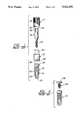
- a procedure which is widely practiced currently, illustrated in FIG. 1,utilizes a kit, contained in a sterile package, that includes a self-tapping implant 14, an insertion tool 15, held to the implant by a screw 16, and a carrier 17.
- the implanthas threads 20, a self-tapping cutting edge 21, a recess 22, formed with the edge 21, which may have a hole 23 leading to a similar recess on the opposite side.
- the recessprovides a place for the bone debris that forms from cutting the threads, thereby avoiding packing of the debris between the implant and the surrounding bone.
- the center of an outer end 24 of the implantis hollow and threaded (not shown) to receive the threads 25 of the screw 16.
- the outer end 24also has a shallow hexagonal land 26 thereon for aligning the ultimate prosthesis (or abutment) therewith and for screwing the implant into the hole drilled into the bone.
- the land 26is engaged by a hexagonal socket 28 formed in the insertion tool 15.
- the upper third (or so) of the insertion tool 16has a hexagonal surface 30 which is engaged, initially by a hexagonal socket 33 formed in the carrier 17; the carrier may have serrations 34, or other features, to assist in handling it.
- the tool 15As shipped in a sterile bottle or other sterile package, the tool 15 is tightly secured over the land 26 by the screw 16, and the carrier 17 surrounds the hex surface 30 of the tool.
- the carriertypically forms the stopper of an interior bottle in a double sterile package.
- the implantmay thus be hand started into the hole in the bone by means of the carrier.
- the carriercan then be shaken loose and removed.
- a socket wrenchis then used to seat the implant subgingivally into the bone.
- a hexagonal wrenchis used to engage a hexagonal socket 36 formed in the outer end 37 of the screw, the screw 16 is backed out of the implant, and the insertion tool 15 is removed.
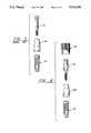
- a healing screw 38(FIG. 2) is threaded tightly into the implant to keep the outer end 24, the land 26 and the internal threads of the implant all clean and clear, as the gum tissue is allowed to heal over the healing screw.
- the healing screw 38has a hex socket in its head 39 (not shown, similar to that of the screw 16) to permit rotating it with a hex wrench.
- the head 39has an annular void to fit over, but not engage, the hexagonal land 26 on the implant 14.
- an impression transfer pin 40(FIG. 3) is secured to the implant 15 by a screw 41.
- the screw 41may be rotated with a friction drive wrench.
- the transfer pin 40is fit tightly to the implant 15 and x-rayed to ensure that it is tight and well mated, with no voids. Then, an impression is taken of the patient's mouth with the transfer pin in place.
- the screw and transfer pinare removed and a healing abutment (not shown) is threaded into the implant; the healing abutment typically extends above the gum line, so that the gum tissue can reheal, leaving an orifice open to the implant for later insertion of a suitable abutment which mounts the prosthesis.
- a laboratoryprepares a working model of the mouth from the impression, utilizing the transfer pins, imbedded in the impression, to seat implant analogs (or dies) to which the prosthesis may be secured on the working model. Then the lab prepares the prosthesis, with the abutments which will be utilized for anchoring the prosthesis on the implants, secured to the implant analogs.
- the transfer pinis typically not provided in the sterile kit.
- the transfer pinscan become nicked and may have bits of material adherent thereto which together provide irregularities in the surface that impede both the seating of the transfer pin securely to the implant, without voids, prior to making the impression, as well as interfering with a faithful return to the impression when the construction is commenced.
- single stage implantswith abutments integrally formed thereon, have been used in a procedure which takes the impression on the mouth immediately after installing the implants.
- This procedurehas not had general acceptance because it must be executed with extreme skill and without any significant anatomical contra indications or procedural mishaps.
- the temporization (protection) of the abutments through the tissueis also difficult.
- the two stage process(hereinbefore) permits compensating for any incorrect angles or other misplacements of the implants.
- the abutment ends of the integrally formed implantsare protected from tongue and chewing pressures for months, to avoid faulty healing. This requires easily adapting an existing denture or providing a temporary prosthesis, to cover the implants during healing.
- Objects of the inventioninclude mounting a bone implant, such as in a patient's mouth for prosthodontic restoration, in a manner requiring a minimal handling of parts, reducing patient visits, with improved results, and significantly reducing the elapsed time from the beginning to the conclusion of the prosthodontic procedure.
- This inventionis predicated in part on the discovery that taking an impression at the first sitting of the patient, immediately following the insertion of the implants into the bone, has no significant pathological morbidity or other detrimental effects.
- the inventionis also predicated on the discovery that the location of implants, utilized in a two-stage process, remain essentially constant so that initial impressions are as accurate as impressions made following a several month healing period.
- a sterile packageincludes an implant having secured thereto a transfer pin which also serves as an insertion tool, the package including a carrier which has a unique interior wall surface engaging the combination insertion tool/transfer pin, so that the implant may be started into the bone in a sterile manner, using the aforementioned components shipped as a sterile set.
- the inventionincludes a method in which an impression is taken as soon as the carrier is removed from the combined insertion tool/transfer pin, (unless contra-indicated) after which the transfer pin is removed and a healing screw is inserted to the outer end of the implant in order to keep it clean for ultimate mating with an abutment which will mount the prosthesis.
- the inventionby taking the impression immediately, allows the laboratory work--forming of the model of the mouth and the ultimate prosthesis and/or abutment structure--to be performed while the initial, several-month healing takes place.
- the inventionavoids having to enter the gum tissue more than twice, since the second invasion is to remove the healing screw and mount the ultimate abutments and/or prosthesis (in most cases).
- One great advantage of the present inventionis that it avoids the necessity for handling a transfer pin and concomitant screw at a second sitting, after healing has taken place. Thus, fewer steps are required, as fewer parts are handled. This significantly reduces the risk of infection as well as significantly reducing the risk of loosing small parts--possibly in a patient.
- Another great advantage of the present inventionis that the transfer pin is always firmly and tightly secured to the implant at the factory, under ideal conditions, rather than being attached to the implant in the surgical field.
- a concomitant advantageis that providing a new insertion pin for each implant avoids the possibility of poor fit to the implant due to scratches in the mating surface of the transfer pin or inter-lodging debris.
- the inventionalso eliminates the use of two parts: the insertion tool and the screw used to hold the original transfer pin.
- FIG. 1is an exploded, partially sectioned side elevation view of a sterile set comprising an implant, an insertion tool, a screw and a carrier known to the prior art.
- FIG. 2is an exploded side elevation view of a healing screw and an implant, known to the prior art.
- FIG. 3is an exploded side elevation view of an implant and a transfer pin together with a screw for securing the transfer pin to the implant, in accordance with the prior art.
- FIG. 4is an exploded, partially sectioned side elevation view of a sterile set comprising an implant, a combined insertion tool/transfer pin, a screw for securing the combined insertion tool/transfer pin to the implant, and a carrier, in accordance with the present invention.
- a combined insertion tool/transfer pin 50may take a variety of forms, the one illustrated herein is a severely timed transfer pin.
- the combined insertion tool/transfer pin 50is hollow all the way through, so as to permit it to be fastened to the implant 14 by means of the screw 16, both of which may be the same as in the prior art.
- the implant 14, combined pin 50 and screw 16are assembled with the screw 16 passing through the combined pin 50 and securing it tightly to the implant 14, with a carrier 52 surrounding the screw 16 and engaging the flat land surface of the combined pin 50 so as to permit transfer of rotary torque thereto sufficiently to start the implant 14 into the hole prepared therefor.
- the parts so assembledare shipped in a sterile container as known in the art, which may comprise a small plastic or glass bottle within a larger bottle, or otherwise, as suits any implementation of the present invention.
- the carrier 52is shaken loose of the combined pin 50 and the screw 16 and removed from the mouth.
- a socket wrenchwith a socket surface shaped to engage the combined pin 50 and/or a screw, is used to drive the implant 14 into its intended position. Then an impression of the mouth is made with the combined pin 50 serving as the transfer pin for the impression.
- a hex wrenchis used to unthread the screw 16 from the implant 14, so that the combined pin 50 can be removed from the mouth.
- a healing screw 38is fastened into the implant 14 (FIG. 2).
- the inventionmay be used with two or several implants.
- the inventionhas an additional advantage that when several implants are being placed, such as may ultimately support a fixed, fixed-removable or other denture, the complete insertion of the first implant while the combined pin 50 remains secured thereto by the screw 16, provides a guide to assist the practitioner in preparing parallel holes at the sites of the additional implants, by visual benchmarking against the combined pin 50.
- the transfer pin 40 and combined pin 50 disclosed hereinhave smooth surfaces, a combined pin in accordance with the present invention may have lateral grooves therein (which tend to snap the transfer pin into the elastic impression), or other transfer pin shapes, as are known in the art.
- the inventionhas been shown with a hex land and socket relationship between the implant and the combined pin 50. This allows assuring reorientation of the transfer pin correctly with respect to the implant. However, it is known to use slots, clover leafs and other shapes to assure registration, all of which are within the scope of this invention.
- the combined pin 50may comprise a temporary or permanent abutment utilized to make the impression for the model of the mouth, after which it could remain in place during healing (as a healing abutment or to anchor a temporary prosthesis), and/or used as the ultimate abutment. In that situation, an abutment analog may be used in constructing the prosthesis to the model of the mouth.
- the inventionis not limited to prosthodontia, but may be used in securing any form of artificial body part to bone, specifically including eyes, ears and noses and subcutaneous structures for supporting living or non-living reconstructions thereof.
- the transfer pinbe utilized as an insertion tool so as to permit taking an impression immediately after inserting the implant, the field remaining sterile because of the kit according to the invention, which does not require exchanging an insertion tool with a transfer pin.
- One of the great advantages of the inventionis having the laboratory work commence immediately upon inserting the implants into the bone, due to the presence of the combined pin 50 in the sterile kit.
- the practitionermust, as always, make clinical decisions about the appropriateness of any stage of a procedure. Should the practitioner decide that the impressions should not be made immediately upon placement of the implants as described hereinbefore, then the taking of the impression can be delayed. An example might be where there is unusual trauma from site preparation.
Landscapes
- Health & Medical Sciences (AREA)
- Oral & Maxillofacial Surgery (AREA)
- Dentistry (AREA)
- Epidemiology (AREA)
- Life Sciences & Earth Sciences (AREA)
- Animal Behavior & Ethology (AREA)
- General Health & Medical Sciences (AREA)
- Public Health (AREA)
- Veterinary Medicine (AREA)
- Orthopedic Medicine & Surgery (AREA)
- Dental Prosthetics (AREA)
- Prostheses (AREA)
Abstract
Description
Claims (12)
Priority Applications (2)
| Application Number | Priority Date | Filing Date | Title |
|---|---|---|---|
| US08/037,773US5312254A (en) | 1993-03-26 | 1993-03-26 | Sterile application of implants in bone |
| PCT/US1994/003270WO1994022389A1 (en) | 1993-03-26 | 1994-03-25 | Sterile application of implants in bone |
Applications Claiming Priority (1)
| Application Number | Priority Date | Filing Date | Title |
|---|---|---|---|
| US08/037,773US5312254A (en) | 1993-03-26 | 1993-03-26 | Sterile application of implants in bone |
Publications (1)
| Publication Number | Publication Date |
|---|---|
| US5312254Atrue US5312254A (en) | 1994-05-17 |
Family
ID=21896259
Family Applications (1)
| Application Number | Title | Priority Date | Filing Date |
|---|---|---|---|
| US08/037,773Expired - LifetimeUS5312254A (en) | 1993-03-26 | 1993-03-26 | Sterile application of implants in bone |
Country Status (2)
| Country | Link |
|---|---|
| US (1) | US5312254A (en) |
| WO (1) | WO1994022389A1 (en) |
Cited By (84)
| Publication number | Priority date | Publication date | Assignee | Title |
|---|---|---|---|---|
| US5368160A (en)* | 1993-12-21 | 1994-11-29 | Calcitek, Inc. | Sterile packaging for dental implant system |
| US5538428A (en)* | 1994-04-05 | 1996-07-23 | Attachments International | Packing delivery system for dental implant and method |
| US5558230A (en)* | 1995-06-07 | 1996-09-24 | Ultradent Products | Dental implant container with cap for holding a dental implant and healing screw |
| US5622499A (en)* | 1995-04-10 | 1997-04-22 | Simmons; William E. | Method of manufacturing a dental abutment |
| US5685715A (en)* | 1995-03-10 | 1997-11-11 | Beaty; Keith D. | Self-indexing transfer impression coping |
| WO1998003130A1 (en)* | 1996-07-18 | 1998-01-29 | Biohorizons, Inc. | Abutment-mount system for dental implants |
| US5755575A (en)* | 1996-08-16 | 1998-05-26 | Sulzer Calcitek, Inc. | Dental implant delivery system and method |
| US5823777A (en)* | 1994-12-15 | 1998-10-20 | Biohorizons, Inc. | Dental implants to optimize cellular response |
| USD401694S (en) | 1996-12-02 | 1998-11-24 | Fereidoun Daftary | Anatomic implant |
| US5842865A (en)* | 1997-09-12 | 1998-12-01 | Sulzer Calcitek Inc. | Self-tapping implant with multiple concave tapping channels |
| WO1998055039A1 (en) | 1997-06-02 | 1998-12-10 | Institut Straumann Ag | Retaining element for an implant and ampoule for preserving said implant |
| US5851197A (en)* | 1997-02-05 | 1998-12-22 | Minimed Inc. | Injector for a subcutaneous infusion set |
| US5938443A (en)* | 1994-11-08 | 1999-08-17 | Implant Innovations, Inc. | Impression coping for use in an open tray and closed tray impression methodology |
| US5961330A (en)* | 1998-04-09 | 1999-10-05 | Sulzer Calcitek Inc. | Vial for dental implant delivery system |
| US5964591A (en)* | 1997-04-09 | 1999-10-12 | Implant Innovations, Inc. | Implant delivery system |
| US6068480A (en)* | 1996-07-18 | 2000-05-30 | Biohorizons Implant Systems, Inc. | Abutment-mount with square driving surface |
| US6076660A (en)* | 1998-02-05 | 2000-06-20 | Sulzer Calcitek Inc. | Vial for dental implant delivery system |
| US6086371A (en)* | 1998-02-05 | 2000-07-11 | Sulzer Orthopedics Inc. | Dental implant delivery system having driver mount with removable flange |
| WO2001012098A1 (en)* | 1999-08-19 | 2001-02-22 | Arthur Ashman | Kit for immediate post-extraction implantation |
| US6203323B1 (en) | 1998-04-08 | 2001-03-20 | Implant Innovations, Inc. | Implant delivery system |
| US6206696B1 (en) | 1999-12-10 | 2001-03-27 | Sulzer Calcitek Inc. | Driver tool for one step implant delivery system |
| US6217332B1 (en) | 1998-07-13 | 2001-04-17 | Nobel Biocare Ab | Combination implant carrier and vial cap |
| US6247933B1 (en) | 1999-12-10 | 2001-06-19 | Sulzer Dental Inc. | Dental implant delivery system |
| US6283752B1 (en) | 1998-07-13 | 2001-09-04 | Nobel Biocare Ab | Universal impression coping system |
| US6287117B1 (en)* | 1999-04-22 | 2001-09-11 | Sulzer Dental Inc. | Endosseous dental implants including a healing screw and an optional implant extender |
| US6312260B1 (en) | 1998-08-12 | 2001-11-06 | Nobel Biocare Ab | One-step threaded implant |
| US6315562B1 (en) | 1998-07-13 | 2001-11-13 | Nobel Biocare Usa, Inc. | Implant carrier with gripping fingers |
| WO2002026157A1 (en) | 2000-09-29 | 2002-04-04 | Biohex Corporation | Dental implant system and additional methods of attachment |
| US6416324B1 (en) | 1999-12-10 | 2002-07-09 | Sulzer Dental Inc. | One step dental implant delivery system |
| US6454567B1 (en)* | 2001-04-23 | 2002-09-24 | Ace Surgical Supply Co., Inc. | Dental implant delivery and drive tool |
| US20030054319A1 (en)* | 2001-09-17 | 2003-03-20 | Christopher Gervais | Impression post and temporary abutment and method of making dental restoration |
| US20030054318A1 (en)* | 2001-09-17 | 2003-03-20 | Christopher Gervais | Torque limiting implant drive system |
| US6558162B1 (en) | 1999-11-10 | 2003-05-06 | Implant Innovations, Inc. | Healing components for use in taking impressions and methods for making the same |
| US6561805B2 (en) | 1999-08-12 | 2003-05-13 | Nobel Biocare Ab | Universal implant delivery system |
| US6565357B1 (en)* | 1993-04-08 | 2003-05-20 | Implant Innovations, Inc. | Two-piece healing abutment system |
| US6619958B2 (en) | 1997-04-09 | 2003-09-16 | Implant Innovations, Inc. | Implant delivery system |
| US20030224325A1 (en)* | 2002-06-04 | 2003-12-04 | Ajay Kumar | Dental tool with rententive feature |
| US6663390B2 (en) | 2001-05-14 | 2003-12-16 | Centerpulse Dental Inc. | Near net tooth shaped ceramic crown |
| US20040002682A1 (en)* | 1997-02-05 | 2004-01-01 | Medtronic Minimed, Inc. | Insertion device for an insertion set and method of using the same |
| US20040043358A1 (en)* | 2002-01-11 | 2004-03-04 | Howlett Charles W. | Dental implant delivery system |
| US6726724B2 (en)* | 2000-12-26 | 2004-04-27 | John A. Repicci | Prosthetic knee |
| US6790040B2 (en) | 1999-11-10 | 2004-09-14 | Implant Innovations, Inc. | Healing components for use in taking impressions and methods for making the same |
| US20050023166A1 (en)* | 2003-07-31 | 2005-02-03 | Howlett Charles W. | Dental implant packaging system |
| US6854972B1 (en) | 2000-01-11 | 2005-02-15 | Nicholas Elian | Dental implants and dental implant/prosthetic tooth systems |
| US20060078847A1 (en)* | 2000-09-29 | 2006-04-13 | Kwan Norman H | Dental implant system and additional methods of attachment |
| US20070092854A1 (en)* | 2005-10-24 | 2007-04-26 | Powell Theodore M | Methods for manufacturing dental implant components |
| US20100086900A1 (en)* | 2008-05-06 | 2010-04-08 | Keystone Dental, Inc. | Coping-analogue kit |
| US20110014586A1 (en)* | 2007-05-16 | 2011-01-20 | Nobel Biocare Services Ag | Ceramic one-piece dental implant |
| US20110040256A1 (en)* | 1997-02-05 | 2011-02-17 | Medtronic Minimed, Inc. | Insertion Device for an Insertion Set and Method of Using the Same |
| US20110123951A1 (en)* | 2009-11-24 | 2011-05-26 | Zimmer Dental, Inc. | Porous Implant Device With Improved Core |
| US8075312B2 (en) | 2005-08-30 | 2011-12-13 | Zimmer Dental, Inc. | Dental implant with improved osseointegration features |
| US8185224B2 (en) | 2005-06-30 | 2012-05-22 | Biomet 3I, Llc | Method for manufacturing dental implant components |
| US8206153B2 (en) | 2007-05-18 | 2012-06-26 | Biomet 3I, Inc. | Method for selecting implant components |
| US8221121B2 (en) | 2008-04-16 | 2012-07-17 | Biomet 3I, Llc | Method for pre-operative visualization of instrumentation used with a surgical guide for dental implant placement |
| US8231387B2 (en) | 2008-07-02 | 2012-07-31 | Zimmer, Inc. | Porous implant with non-porous threads |
| US8257083B2 (en) | 2005-10-24 | 2012-09-04 | Biomet 3I, Llc | Methods for placing an implant analog in a physical model of the patient's mouth |
| US8562348B2 (en) | 2008-07-02 | 2013-10-22 | Zimmer Dental, Inc. | Modular implant with secured porous portion |
| US8562346B2 (en) | 2005-08-30 | 2013-10-22 | Zimmer Dental, Inc. | Dental implant for a jaw with reduced bone volume and improved osseointegration features |
| US8636511B2 (en) | 2002-11-13 | 2014-01-28 | Biomet 3I, Llc | Dental implant system |
| US8651858B2 (en) | 2008-04-15 | 2014-02-18 | Biomet 3I, Llc | Method of creating an accurate bone and soft-tissue digital dental model |
| US8727774B1 (en) | 2011-12-23 | 2014-05-20 | Thomas Arendt | Dental implant carrier device and implant carrier device assembly |
| US8777612B2 (en) | 2007-11-16 | 2014-07-15 | Biomet 3I, Llc | Components for use with a surgical guide for dental implant placement |
| US8814567B2 (en) | 2005-05-26 | 2014-08-26 | Zimmer Dental, Inc. | Dental implant prosthetic device with improved osseointegration and esthetic features |
| US8851891B2 (en) | 2008-11-06 | 2014-10-07 | Zimmer Dental, Inc. | Expandable bone implant |
| US8882508B2 (en) | 2010-12-07 | 2014-11-11 | Biomet 3I, Llc | Universal scanning member for use on dental implant and dental implant analogs |
| US8899982B2 (en) | 2008-07-02 | 2014-12-02 | Zimmer Dental, Inc. | Implant with structure for securing a porous portion |
| US8926328B2 (en) | 2012-12-27 | 2015-01-06 | Biomet 3I, Llc | Jigs for placing dental implant analogs in models and methods of doing the same |
| US8944816B2 (en) | 2011-05-16 | 2015-02-03 | Biomet 3I, Llc | Temporary abutment with combination of scanning features and provisionalization features |
| US20150111175A1 (en)* | 2013-10-22 | 2015-04-23 | Jjgc Industria E Comercio De Materiais Dentarios S.A. | Multifunctional prosthetic component and its method of use |
| US9089382B2 (en) | 2012-01-23 | 2015-07-28 | Biomet 3I, Llc | Method and apparatus for recording spatial gingival soft tissue relationship to implant placement within alveolar bone for immediate-implant placement |
| US9095396B2 (en) | 2008-07-02 | 2015-08-04 | Zimmer Dental, Inc. | Porous implant with non-porous threads |
| US9149345B2 (en) | 2007-08-30 | 2015-10-06 | Zimmer Dental, Inc. | Multiple root implant |
| US9452032B2 (en) | 2012-01-23 | 2016-09-27 | Biomet 3I, Llc | Soft tissue preservation temporary (shell) immediate-implant abutment with biological active surface |
| US9668834B2 (en) | 2013-12-20 | 2017-06-06 | Biomet 3I, Llc | Dental system for developing custom prostheses through scanning of coded members |
| US9700390B2 (en) | 2014-08-22 | 2017-07-11 | Biomet 3I, Llc | Soft-tissue preservation arrangement and method |
| US9707058B2 (en) | 2009-07-10 | 2017-07-18 | Zimmer Dental, Inc. | Patient-specific implants with improved osseointegration |
| US9839496B2 (en) | 2013-02-19 | 2017-12-12 | Biomet 3I, Llc | Patient-specific dental prosthesis and gingival contouring developed by predictive modeling |
| US9925024B2 (en) | 2011-06-28 | 2018-03-27 | Biomet 3I, Llc | Dental implant and abutment tools |
| US10449018B2 (en) | 2015-03-09 | 2019-10-22 | Stephen J. Chu | Gingival ovate pontic and methods of using the same |
| US10813729B2 (en) | 2012-09-14 | 2020-10-27 | Biomet 3I, Llc | Temporary dental prosthesis for use in developing final dental prosthesis |
| US11065090B2 (en) | 2013-04-09 | 2021-07-20 | Biom et 3I, LLC | Dental implant with coded upper surface |
| US11219511B2 (en) | 2005-10-24 | 2022-01-11 | Biomet 3I, Llc | Methods for placing an implant analog in a physical model of the patient's mouth |
| US11406469B2 (en) | 2020-06-10 | 2022-08-09 | GetSet Surgical SA | No touch sterile medical device packaging |
| US12042355B2 (en)* | 2016-05-20 | 2024-07-23 | Nobel Biocare Services Ag | Handling tool, dental set and method for assembling a dental component |
Families Citing this family (1)
| Publication number | Priority date | Publication date | Assignee | Title |
|---|---|---|---|---|
| FR2734707B1 (en)* | 1995-05-30 | 1997-08-29 | Guedj Leon | DENTAL IMPLANTOLOGY SURGICAL EQUIPMENT AND ELEMENTS, DENTAL IMPLANT AND DRILLING INSTRUMENTS, COMPONENTS |
Citations (8)
| Publication number | Priority date | Publication date | Assignee | Title |
|---|---|---|---|---|
| US4856648A (en)* | 1987-12-31 | 1989-08-15 | Steri-Oss, Inc. | Packaging & installing implants |
| US4856994A (en)* | 1988-01-25 | 1989-08-15 | Implant Innovations, Inc. | Periodontal restoration components |
| FR2635455A1 (en)* | 1988-08-22 | 1990-02-23 | Yeung Jean Claude | Prosthesis assembly for dental implant |
| US4955811A (en)* | 1988-06-23 | 1990-09-11 | Implant Innovations, Inc. | Non-rotational single-tooth prosthodontic restoration |
| US5062800A (en)* | 1990-03-21 | 1991-11-05 | Core-Vent Corporation | Dental implant handle, and dental implant package including a dental implant handle |
| US5100323A (en)* | 1990-09-05 | 1992-03-31 | Impla-Med Incorporated | Dental implant |
| US5106300A (en)* | 1990-09-26 | 1992-04-21 | Voitik Anton J | Dental implant attachment structure and method |
| US5180303A (en)* | 1988-09-21 | 1993-01-19 | Regents Of The University Of California | Retrievable dental prothesis apparatus and method of fabrication |
- 1993
- 1993-03-26USUS08/037,773patent/US5312254A/ennot_activeExpired - Lifetime
- 1994
- 1994-03-25WOPCT/US1994/003270patent/WO1994022389A1/enactiveApplication Filing
Patent Citations (8)
| Publication number | Priority date | Publication date | Assignee | Title |
|---|---|---|---|---|
| US4856648A (en)* | 1987-12-31 | 1989-08-15 | Steri-Oss, Inc. | Packaging & installing implants |
| US4856994A (en)* | 1988-01-25 | 1989-08-15 | Implant Innovations, Inc. | Periodontal restoration components |
| US4955811A (en)* | 1988-06-23 | 1990-09-11 | Implant Innovations, Inc. | Non-rotational single-tooth prosthodontic restoration |
| FR2635455A1 (en)* | 1988-08-22 | 1990-02-23 | Yeung Jean Claude | Prosthesis assembly for dental implant |
| US5180303A (en)* | 1988-09-21 | 1993-01-19 | Regents Of The University Of California | Retrievable dental prothesis apparatus and method of fabrication |
| US5062800A (en)* | 1990-03-21 | 1991-11-05 | Core-Vent Corporation | Dental implant handle, and dental implant package including a dental implant handle |
| US5100323A (en)* | 1990-09-05 | 1992-03-31 | Impla-Med Incorporated | Dental implant |
| US5106300A (en)* | 1990-09-26 | 1992-04-21 | Voitik Anton J | Dental implant attachment structure and method |
Cited By (166)
| Publication number | Priority date | Publication date | Assignee | Title |
|---|---|---|---|---|
| US6565357B1 (en)* | 1993-04-08 | 2003-05-20 | Implant Innovations, Inc. | Two-piece healing abutment system |
| US5368160A (en)* | 1993-12-21 | 1994-11-29 | Calcitek, Inc. | Sterile packaging for dental implant system |
| US5538428A (en)* | 1994-04-05 | 1996-07-23 | Attachments International | Packing delivery system for dental implant and method |
| US6290499B1 (en) | 1994-11-08 | 2001-09-18 | Implant Innovations, Inc. | Transfer-type impression coping |
| US5938443A (en)* | 1994-11-08 | 1999-08-17 | Implant Innovations, Inc. | Impression coping for use in an open tray and closed tray impression methodology |
| US6083004A (en)* | 1994-12-15 | 2000-07-04 | Biohorizons Implant Systems, Inc. | Abutment-mount system for dental implants |
| US5927979A (en)* | 1994-12-15 | 1999-07-27 | Biohorizons Implants Systems, Inc. | Abutment-mount system for dental implants |
| US5823777A (en)* | 1994-12-15 | 1998-10-20 | Biohorizons, Inc. | Dental implants to optimize cellular response |
| US5685715A (en)* | 1995-03-10 | 1997-11-11 | Beaty; Keith D. | Self-indexing transfer impression coping |
| US5622499A (en)* | 1995-04-10 | 1997-04-22 | Simmons; William E. | Method of manufacturing a dental abutment |
| US5558230A (en)* | 1995-06-07 | 1996-09-24 | Ultradent Products | Dental implant container with cap for holding a dental implant and healing screw |
| WO1998003130A1 (en)* | 1996-07-18 | 1998-01-29 | Biohorizons, Inc. | Abutment-mount system for dental implants |
| US6068480A (en)* | 1996-07-18 | 2000-05-30 | Biohorizons Implant Systems, Inc. | Abutment-mount with square driving surface |
| US5755575A (en)* | 1996-08-16 | 1998-05-26 | Sulzer Calcitek, Inc. | Dental implant delivery system and method |
| USD455833S1 (en) | 1996-12-02 | 2002-04-16 | Fereidoun Daftary | Anatomic implant |
| USD401694S (en) | 1996-12-02 | 1998-11-24 | Fereidoun Daftary | Anatomic implant |
| US8292849B2 (en) | 1997-02-05 | 2012-10-23 | Medtronic Minimed, Inc. | Insertion device for an insertion set and method of using the same |
| US5851197A (en)* | 1997-02-05 | 1998-12-22 | Minimed Inc. | Injector for a subcutaneous infusion set |
| US20040002682A1 (en)* | 1997-02-05 | 2004-01-01 | Medtronic Minimed, Inc. | Insertion device for an insertion set and method of using the same |
| US20070142776A9 (en)* | 1997-02-05 | 2007-06-21 | Medtronic Minimed, Inc. | Insertion device for an insertion set and method of using the same |
| US8641674B2 (en) | 1997-02-05 | 2014-02-04 | Medtronic Minimed, Inc. | Insertion device for an insertion set and method of using the same |
| US20110040256A1 (en)* | 1997-02-05 | 2011-02-17 | Medtronic Minimed, Inc. | Insertion Device for an Insertion Set and Method of Using the Same |
| US8628498B2 (en) | 1997-02-05 | 2014-01-14 | Medtronic Minimed, Inc. | Insertion device for an insertion set and method of using the same |
| US7344376B2 (en) | 1997-04-09 | 2008-03-18 | Biomet 3I, Inc. | Implant delivery system |
| US8087935B2 (en) | 1997-04-09 | 2012-01-03 | Biomet 3I, Llc | Implant delivery system |
| US6619958B2 (en) | 1997-04-09 | 2003-09-16 | Implant Innovations, Inc. | Implant delivery system |
| US5964591A (en)* | 1997-04-09 | 1999-10-12 | Implant Innovations, Inc. | Implant delivery system |
| US20050191600A1 (en)* | 1997-04-09 | 2005-09-01 | Beaty Keith D. | Implant delivery system |
| US6261097B1 (en) | 1997-06-02 | 2001-07-17 | Institut Straumann Ag | Retaining element for an implant and ampoule for preserving said implant |
| WO1998055039A1 (en) | 1997-06-02 | 1998-12-10 | Institut Straumann Ag | Retaining element for an implant and ampoule for preserving said implant |
| US5842865A (en)* | 1997-09-12 | 1998-12-01 | Sulzer Calcitek Inc. | Self-tapping implant with multiple concave tapping channels |
| US6076660A (en)* | 1998-02-05 | 2000-06-20 | Sulzer Calcitek Inc. | Vial for dental implant delivery system |
| US6086371A (en)* | 1998-02-05 | 2000-07-11 | Sulzer Orthopedics Inc. | Dental implant delivery system having driver mount with removable flange |
| US6203323B1 (en) | 1998-04-08 | 2001-03-20 | Implant Innovations, Inc. | Implant delivery system |
| US5961330A (en)* | 1998-04-09 | 1999-10-05 | Sulzer Calcitek Inc. | Vial for dental implant delivery system |
| US6217332B1 (en) | 1998-07-13 | 2001-04-17 | Nobel Biocare Ab | Combination implant carrier and vial cap |
| US6315562B1 (en) | 1998-07-13 | 2001-11-13 | Nobel Biocare Usa, Inc. | Implant carrier with gripping fingers |
| US6283752B1 (en) | 1998-07-13 | 2001-09-04 | Nobel Biocare Ab | Universal impression coping system |
| US6312260B1 (en) | 1998-08-12 | 2001-11-06 | Nobel Biocare Ab | One-step threaded implant |
| US6287117B1 (en)* | 1999-04-22 | 2001-09-11 | Sulzer Dental Inc. | Endosseous dental implants including a healing screw and an optional implant extender |
| US6561805B2 (en) | 1999-08-12 | 2003-05-13 | Nobel Biocare Ab | Universal implant delivery system |
| WO2001012098A1 (en)* | 1999-08-19 | 2001-02-22 | Arthur Ashman | Kit for immediate post-extraction implantation |
| US6312258B1 (en)* | 1999-08-19 | 2001-11-06 | Arthur Ashman | Kit for immediate post-extraction implantation |
| US7988449B2 (en) | 1999-11-10 | 2011-08-02 | Biomet 3I, Llc | Healing components for use in taking impressions and methods for making the same |
| US8758015B2 (en) | 1999-11-10 | 2014-06-24 | Biomet 3I, Llc | Healing components for use in taking impressions and methods for making the same |
| US8353703B2 (en) | 1999-11-10 | 2013-01-15 | Biomet 3I, Llc | Healing components for use in taking impressions and methods for making the same |
| US9795288B2 (en) | 1999-11-10 | 2017-10-24 | Biomet 3I, Llc | Healing components for use in taking impressions and methods for making the same |
| US6790040B2 (en) | 1999-11-10 | 2004-09-14 | Implant Innovations, Inc. | Healing components for use in taking impressions and methods for making the same |
| US20040241611A1 (en)* | 1999-11-10 | 2004-12-02 | Amber John T. | Healing components for use in taking impressions and methods for making the same |
| US6558162B1 (en) | 1999-11-10 | 2003-05-06 | Implant Innovations, Inc. | Healing components for use in taking impressions and methods for making the same |
| US9801533B2 (en) | 1999-11-10 | 2017-10-31 | Biomet 3I, Llc | Healing components for use in taking impressions and methods for making the same |
| US20080233537A1 (en)* | 1999-11-10 | 2008-09-25 | Biomet 3I, Inc. | Healing components for use in taking impressions and methods for making the same |
| US7425131B2 (en) | 1999-11-10 | 2008-09-16 | Biomet 31, Inc. | Healing components for use in taking impressions and methods for making the same |
| US6247933B1 (en) | 1999-12-10 | 2001-06-19 | Sulzer Dental Inc. | Dental implant delivery system |
| US6206696B1 (en) | 1999-12-10 | 2001-03-27 | Sulzer Calcitek Inc. | Driver tool for one step implant delivery system |
| US6416324B1 (en) | 1999-12-10 | 2002-07-09 | Sulzer Dental Inc. | One step dental implant delivery system |
| US6854972B1 (en) | 2000-01-11 | 2005-02-15 | Nicholas Elian | Dental implants and dental implant/prosthetic tooth systems |
| US20060078847A1 (en)* | 2000-09-29 | 2006-04-13 | Kwan Norman H | Dental implant system and additional methods of attachment |
| WO2002026157A1 (en) | 2000-09-29 | 2002-04-04 | Biohex Corporation | Dental implant system and additional methods of attachment |
| US6726724B2 (en)* | 2000-12-26 | 2004-04-27 | John A. Repicci | Prosthetic knee |
| US6454567B1 (en)* | 2001-04-23 | 2002-09-24 | Ace Surgical Supply Co., Inc. | Dental implant delivery and drive tool |
| US6663390B2 (en) | 2001-05-14 | 2003-12-16 | Centerpulse Dental Inc. | Near net tooth shaped ceramic crown |
| US6663387B2 (en) | 2001-05-14 | 2003-12-16 | Centerpulse Dental Inc. | Near net tooth shaped ceramic crown and method |
| US7160109B2 (en) | 2001-09-17 | 2007-01-09 | Sulzer Dental Inc. | Torque limiting implant drive system |
| US20030054318A1 (en)* | 2001-09-17 | 2003-03-20 | Christopher Gervais | Torque limiting implant drive system |
| US20030054319A1 (en)* | 2001-09-17 | 2003-03-20 | Christopher Gervais | Impression post and temporary abutment and method of making dental restoration |
| US7137816B2 (en) | 2001-09-17 | 2006-11-21 | Zimmer Dental Inc. | Impression post and temporary abutment and method of making dental restoration |
| US20040043358A1 (en)* | 2002-01-11 | 2004-03-04 | Howlett Charles W. | Dental implant delivery system |
| US6913465B2 (en) | 2002-01-11 | 2005-07-05 | Nobel Biocare Services Ag | Dental implant delivery system |
| US20030224325A1 (en)* | 2002-06-04 | 2003-12-04 | Ajay Kumar | Dental tool with rententive feature |
| US6951462B2 (en) | 2002-06-04 | 2005-10-04 | Zimmer Dental Inc. | Dental tool with rententive feature |
| US9549793B2 (en) | 2002-11-13 | 2017-01-24 | Biomet 3I, Llc | Dental implant system |
| US8636511B2 (en) | 2002-11-13 | 2014-01-28 | Biomet 3I, Llc | Dental implant system |
| US9931182B2 (en) | 2002-11-13 | 2018-04-03 | Biomet 3I, Llc | Dental implant system |
| US9883927B2 (en) | 2002-11-13 | 2018-02-06 | Biomet 3I, Llc | Dental implant system |
| US20050023166A1 (en)* | 2003-07-31 | 2005-02-03 | Howlett Charles W. | Dental implant packaging system |
| US6955258B2 (en) | 2003-07-31 | 2005-10-18 | Nobel Biocare Ab | Dental implant packaging system |
| US8814567B2 (en) | 2005-05-26 | 2014-08-26 | Zimmer Dental, Inc. | Dental implant prosthetic device with improved osseointegration and esthetic features |
| US11046006B2 (en) | 2005-06-30 | 2021-06-29 | Biomet 3I, Llc | Method for manufacturing dental implant components |
| US12202204B2 (en) | 2005-06-30 | 2025-01-21 | Biomet 31, Llc | Method for manufacturing dental implant components |
| US8855800B2 (en) | 2005-06-30 | 2014-10-07 | Biomet 3I, Llc | Method for manufacturing dental implant components |
| US11897201B2 (en) | 2005-06-30 | 2024-02-13 | Biomet 3I, Llc | Method for manufacturing dental implant components |
| US8185224B2 (en) | 2005-06-30 | 2012-05-22 | Biomet 3I, Llc | Method for manufacturing dental implant components |
| US12202203B2 (en) | 2005-06-30 | 2025-01-21 | Biomet 3I, Llc | Method for manufacturing dental implant components |
| US8612037B2 (en) | 2005-06-30 | 2013-12-17 | Biomet 3I, Llc | Method for manufacturing dental implant components |
| US9108361B2 (en) | 2005-06-30 | 2015-08-18 | Biomet 3I, Llc | Method for manufacturing dental implant components |
| US10022916B2 (en) | 2005-06-30 | 2018-07-17 | Biomet 3I, Llc | Method for manufacturing dental implant components |
| US8562346B2 (en) | 2005-08-30 | 2013-10-22 | Zimmer Dental, Inc. | Dental implant for a jaw with reduced bone volume and improved osseointegration features |
| US8899981B2 (en) | 2005-08-30 | 2014-12-02 | Zimmer Dental, Inc. | Dental implant for a jaw with reduced bone volume and improved osseointegration features |
| US10070945B2 (en) | 2005-08-30 | 2018-09-11 | Zimmer Dental, Inc. | Dental implant for a jaw with reduced bone volume and improved osseointegration features |
| US8075312B2 (en) | 2005-08-30 | 2011-12-13 | Zimmer Dental, Inc. | Dental implant with improved osseointegration features |
| US12329608B2 (en) | 2005-10-24 | 2025-06-17 | Biomet 3I, Llc | Methods for placing an implant analog in a physical model of the patient's mouth |
| US8690574B2 (en) | 2005-10-24 | 2014-04-08 | Biomet 3I, Llc | Methods for placing an implant analog in a physical model of the patient's mouth |
| US8257083B2 (en) | 2005-10-24 | 2012-09-04 | Biomet 3I, Llc | Methods for placing an implant analog in a physical model of the patient's mouth |
| US10307227B2 (en) | 2005-10-24 | 2019-06-04 | Biomet 3I, Llc | Methods for placing an implant analog in a physical model of the patient's mouth |
| US8998614B2 (en) | 2005-10-24 | 2015-04-07 | Biomet 3I, Llc | Methods for placing an implant analog in a physical model of the patient's mouth |
| US7661956B2 (en) | 2005-10-24 | 2010-02-16 | Biomet 3I, Llc | Methods for manufacturing dental implant components |
| US11219511B2 (en) | 2005-10-24 | 2022-01-11 | Biomet 3I, Llc | Methods for placing an implant analog in a physical model of the patient's mouth |
| US11896459B2 (en) | 2005-10-24 | 2024-02-13 | Biomet 3I, Llc | Methods for placing an implant analog in a physical model of the patient's mouth |
| US8011925B2 (en) | 2005-10-24 | 2011-09-06 | Biomet 3I, Llc | Methods for manufacturing dental implant components |
| US20070092854A1 (en)* | 2005-10-24 | 2007-04-26 | Powell Theodore M | Methods for manufacturing dental implant components |
| US20110014586A1 (en)* | 2007-05-16 | 2011-01-20 | Nobel Biocare Services Ag | Ceramic one-piece dental implant |
| US10368963B2 (en) | 2007-05-18 | 2019-08-06 | Biomet 3I, Llc | Method for selecting implant components |
| US10925694B2 (en) | 2007-05-18 | 2021-02-23 | Biomet 3I, Llc | Method for selecting implant components |
| US9888985B2 (en) | 2007-05-18 | 2018-02-13 | Biomet 3I, Llc | Method for selecting implant components |
| US8206153B2 (en) | 2007-05-18 | 2012-06-26 | Biomet 3I, Inc. | Method for selecting implant components |
| US9089380B2 (en) | 2007-05-18 | 2015-07-28 | Biomet 3I, Llc | Method for selecting implant components |
| US9149345B2 (en) | 2007-08-30 | 2015-10-06 | Zimmer Dental, Inc. | Multiple root implant |
| US8967999B2 (en) | 2007-11-16 | 2015-03-03 | Biomet 3I, Llc | Components for use with a surgical guide for dental implant placement |
| US9011146B2 (en) | 2007-11-16 | 2015-04-21 | Biomet 3I, Llc | Components for use with a surgical guide for dental implant placement |
| US10667885B2 (en) | 2007-11-16 | 2020-06-02 | Biomet 3I, Llc | Components for use with a surgical guide for dental implant placement |
| US8777612B2 (en) | 2007-11-16 | 2014-07-15 | Biomet 3I, Llc | Components for use with a surgical guide for dental implant placement |
| US11207153B2 (en) | 2007-11-16 | 2021-12-28 | Biomet 3I, Llc | Components for use with a surgical guide for dental implant placement |
| US8870574B2 (en) | 2008-04-15 | 2014-10-28 | Biomet 3I, Llc | Method of creating an accurate bone and soft-tissue digital dental model |
| US8651858B2 (en) | 2008-04-15 | 2014-02-18 | Biomet 3I, Llc | Method of creating an accurate bone and soft-tissue digital dental model |
| US9204941B2 (en) | 2008-04-15 | 2015-12-08 | Biomet 3I, Llc | Method of creating an accurate bone and soft-tissue digital dental model |
| US9848836B2 (en) | 2008-04-15 | 2017-12-26 | Biomet 3I, Llc | Method of creating an accurate bone and soft-tissue digital dental model |
| US9795345B2 (en) | 2008-04-16 | 2017-10-24 | Biomet 3I, Llc | Method for pre-operative visualization of instrumentation used with a surgical guide for dental implant placement |
| US8221121B2 (en) | 2008-04-16 | 2012-07-17 | Biomet 3I, Llc | Method for pre-operative visualization of instrumentation used with a surgical guide for dental implant placement |
| US8888488B2 (en) | 2008-04-16 | 2014-11-18 | Biomet 3I, Llc | Method for pre-operative visualization of instrumentation used with a surgical guide for dental implant placement |
| US11154258B2 (en) | 2008-04-16 | 2021-10-26 | Biomet 3I, Llc | Method for pre-operative visualization of instrumentation used with a surgical guide for dental implant placement |
| US8414296B2 (en) | 2008-04-16 | 2013-04-09 | Biomet 3I, Llc | Method for pre-operative visualization of instrumentation used with a surgical guide for dental implant placement |
| US20100086900A1 (en)* | 2008-05-06 | 2010-04-08 | Keystone Dental, Inc. | Coping-analogue kit |
| US8562348B2 (en) | 2008-07-02 | 2013-10-22 | Zimmer Dental, Inc. | Modular implant with secured porous portion |
| US9095396B2 (en) | 2008-07-02 | 2015-08-04 | Zimmer Dental, Inc. | Porous implant with non-porous threads |
| US9066771B2 (en) | 2008-07-02 | 2015-06-30 | Zimmer Dental, Inc. | Modular implant with secured porous portion |
| US8899982B2 (en) | 2008-07-02 | 2014-12-02 | Zimmer Dental, Inc. | Implant with structure for securing a porous portion |
| US8231387B2 (en) | 2008-07-02 | 2012-07-31 | Zimmer, Inc. | Porous implant with non-porous threads |
| US9744007B2 (en) | 2008-11-06 | 2017-08-29 | Zimmer Dental, Inc. | Expandable bone implant |
| US8851891B2 (en) | 2008-11-06 | 2014-10-07 | Zimmer Dental, Inc. | Expandable bone implant |
| US9707058B2 (en) | 2009-07-10 | 2017-07-18 | Zimmer Dental, Inc. | Patient-specific implants with improved osseointegration |
| US9901424B2 (en) | 2009-11-24 | 2018-02-27 | Zimmer Dental, Inc. | Porous implant device with improved core |
| US10687919B2 (en) | 2009-11-24 | 2020-06-23 | Zimmer Dental, Inc. | Porous implant device with improved core |
| US9439738B2 (en) | 2009-11-24 | 2016-09-13 | Zimmer Dental, Inc. | Porous implant device with improved core |
| US8602782B2 (en) | 2009-11-24 | 2013-12-10 | Zimmer Dental, Inc. | Porous implant device with improved core |
| US20110123951A1 (en)* | 2009-11-24 | 2011-05-26 | Zimmer Dental, Inc. | Porous Implant Device With Improved Core |
| US8882508B2 (en) | 2010-12-07 | 2014-11-11 | Biomet 3I, Llc | Universal scanning member for use on dental implant and dental implant analogs |
| US9662185B2 (en) | 2010-12-07 | 2017-05-30 | Biomet 3I, Llc | Universal scanning member for use on dental implant and dental implant analogs |
| US10368964B2 (en) | 2011-05-16 | 2019-08-06 | Biomet 3I, Llc | Temporary abutment with combination of scanning features and provisionalization features |
| US11389275B2 (en) | 2011-05-16 | 2022-07-19 | Biomet 3I, Llc | Temporary abutment with combination of scanning features and provisionalization features |
| US8944816B2 (en) | 2011-05-16 | 2015-02-03 | Biomet 3I, Llc | Temporary abutment with combination of scanning features and provisionalization features |
| US8944818B2 (en) | 2011-05-16 | 2015-02-03 | Biomet 3I, Llc | Temporary abutment with combination of scanning features and provisionalization features |
| US9925024B2 (en) | 2011-06-28 | 2018-03-27 | Biomet 3I, Llc | Dental implant and abutment tools |
| US10952826B2 (en) | 2011-06-28 | 2021-03-23 | Biomet 3I, Llc | System and method of dental implant and interface to abutment for restoration |
| US8727774B1 (en) | 2011-12-23 | 2014-05-20 | Thomas Arendt | Dental implant carrier device and implant carrier device assembly |
| US9452032B2 (en) | 2012-01-23 | 2016-09-27 | Biomet 3I, Llc | Soft tissue preservation temporary (shell) immediate-implant abutment with biological active surface |
| US9474588B2 (en) | 2012-01-23 | 2016-10-25 | Biomet 3I, Llc | Method and apparatus for recording spatial gingival soft tissue relationship to implant placement within alveolar bone for immediate-implant placement |
| US10335254B2 (en) | 2012-01-23 | 2019-07-02 | Evollution IP Holdings Inc. | Method and apparatus for recording spatial gingival soft tissue relationship to implant placement within alveolar bone for immediate-implant placement |
| US9089382B2 (en) | 2012-01-23 | 2015-07-28 | Biomet 3I, Llc | Method and apparatus for recording spatial gingival soft tissue relationship to implant placement within alveolar bone for immediate-implant placement |
| US10813729B2 (en) | 2012-09-14 | 2020-10-27 | Biomet 3I, Llc | Temporary dental prosthesis for use in developing final dental prosthesis |
| US8926328B2 (en) | 2012-12-27 | 2015-01-06 | Biomet 3I, Llc | Jigs for placing dental implant analogs in models and methods of doing the same |
| US10092379B2 (en) | 2012-12-27 | 2018-10-09 | Biomet 3I, Llc | Jigs for placing dental implant analogs in models and methods of doing the same |
| US9839496B2 (en) | 2013-02-19 | 2017-12-12 | Biomet 3I, Llc | Patient-specific dental prosthesis and gingival contouring developed by predictive modeling |
| US10959816B2 (en) | 2013-02-19 | 2021-03-30 | Biomet 3I, Llc | Patient-specific dental prosthesis and gingival contouring developed by predictive modeling |
| US11864975B2 (en) | 2013-04-09 | 2024-01-09 | Biomet 3I, Llc | Dental implant with coded upper surface |
| US11065090B2 (en) | 2013-04-09 | 2021-07-20 | Biom et 3I, LLC | Dental implant with coded upper surface |
| US9579168B2 (en)* | 2013-10-22 | 2017-02-28 | Jjgc Industria E Comercio De Materiais Dentarios S.A. | Multifunctional prosthetic component and its method of use |
| US20150111175A1 (en)* | 2013-10-22 | 2015-04-23 | Jjgc Industria E Comercio De Materiais Dentarios S.A. | Multifunctional prosthetic component and its method of use |
| US10092377B2 (en) | 2013-12-20 | 2018-10-09 | Biomet 3I, Llc | Dental system for developing custom prostheses through scanning of coded members |
| US10842598B2 (en) | 2013-12-20 | 2020-11-24 | Biomet 3I, Llc | Dental system for developing custom prostheses through scanning of coded members |
| US9668834B2 (en) | 2013-12-20 | 2017-06-06 | Biomet 3I, Llc | Dental system for developing custom prostheses through scanning of coded members |
| US9700390B2 (en) | 2014-08-22 | 2017-07-11 | Biomet 3I, Llc | Soft-tissue preservation arrangement and method |
| US11571282B2 (en) | 2015-03-09 | 2023-02-07 | Keystone Dental, Inc. | Gingival ovate pontic and methods of using the same |
| US10449018B2 (en) | 2015-03-09 | 2019-10-22 | Stephen J. Chu | Gingival ovate pontic and methods of using the same |
| US12042355B2 (en)* | 2016-05-20 | 2024-07-23 | Nobel Biocare Services Ag | Handling tool, dental set and method for assembling a dental component |
| US11406469B2 (en) | 2020-06-10 | 2022-08-09 | GetSet Surgical SA | No touch sterile medical device packaging |
Also Published As
| Publication number | Publication date |
|---|---|
| WO1994022389A1 (en) | 1994-10-13 |
Similar Documents
| Publication | Publication Date | Title |
|---|---|---|
| US5312254A (en) | Sterile application of implants in bone | |
| US8087935B2 (en) | Implant delivery system | |
| US6843653B2 (en) | Dental implant | |
| US6083004A (en) | Abutment-mount system for dental implants | |
| US5964591A (en) | Implant delivery system | |
| EP1628593B1 (en) | Prosthesis mounting device and assembly | |
| US6206696B1 (en) | Driver tool for one step implant delivery system | |
| US6416324B1 (en) | One step dental implant delivery system | |
| US6655961B2 (en) | Modified dental implant fixture | |
| US5989028A (en) | Non-submergible, one-part, root-form endosseous dental implants | |
| US7632095B2 (en) | Method for forming a dental prosthesis | |
| US6045361A (en) | Ball-topped screw for facilitating the making of an impression of a dental implant and method of using the same | |
| US20110151408A1 (en) | Dental platform assembly and methods | |
| JP2000300582A (en) | Endo-osseous root-shaped dental implant and implant extension | |
| WO1998003130A9 (en) | Abutment-mount system for dental implants | |
| JP2002520084A (en) | Combination implant holder and vial cap | |
| CN101146490A (en) | Narrow dental implants and related components | |
| US6203323B1 (en) | Implant delivery system |
Legal Events
| Date | Code | Title | Description |
|---|---|---|---|
| STPP | Information on status: patent application and granting procedure in general | Free format text:APPLICATION UNDERGOING PREEXAM PROCESSING | |
| AS | Assignment | Owner name:FIRST SOURCE FINANCIAL LLP, ILLINOIS Free format text:AGREEMENT (PATENT);ASSIGNOR:S-O OPERATING CORP.;REEL/FRAME:008268/0965 Effective date:19961115 | |
| FPAY | Fee payment | Year of fee payment:4 | |
| FEPP | Fee payment procedure | Free format text:PAYOR NUMBER ASSIGNED (ORIGINAL EVENT CODE: ASPN); ENTITY STATUS OF PATENT OWNER: LARGE ENTITY | |
| FEPP | Fee payment procedure | Free format text:PAT HOLDER NO LONGER CLAIMS SMALL ENTITY STATUS, ENTITY STATUS SET TO UNDISCOUNTED (ORIGINAL EVENT CODE: STOL); ENTITY STATUS OF PATENT OWNER: LARGE ENTITY | |
| FPAY | Fee payment | Year of fee payment:8 | |
| REMI | Maintenance fee reminder mailed | ||
| AS | Assignment | Owner name:CENTERPULSE DENTAL INC., CALIFORNIA Free format text:ASSIGNMENT OF ASSIGNORS INTEREST;ASSIGNOR:SUZLER DENTAL INC.;REEL/FRAME:013525/0490 Effective date:20020930 | |
| AS | Assignment | Owner name:ZIMMER DENTAL, INC., CALIFORNIA Free format text:CHANGE OF NAME;ASSIGNOR:CENTERPULSE DENTAL INC.;REEL/FRAME:015629/0191 Effective date:20040108 | |
| AS | Assignment | Owner name:SULZER DENTAL, INC., CALIFORNIA Free format text:ASSIGNMENT OF ASSIGNORS INTEREST;ASSIGNOR:ROSENLICHT, JOEL DR.;REEL/FRAME:015711/0947 Effective date:20010716 | |
| AS | Assignment | Owner name:SULZER DENTAL INC., CALIFORNIA Free format text:ASSIGNMENT OF ASSIGNORS INTEREST;ASSIGNOR:ROSENLICHT, JOEL, M.D.;REEL/FRAME:015980/0068 Effective date:20010716 | |
| FPAY | Fee payment | Year of fee payment:12 |