US5312212A - Axially compliant tool holder - Google Patents
Axially compliant tool holderDownload PDFInfo
- Publication number
- US5312212A US5312212AUS07/952,429US95242992AUS5312212AUS 5312212 AUS5312212 AUS 5312212AUS 95242992 AUS95242992 AUS 95242992AUS 5312212 AUS5312212 AUS 5312212A
- Authority
- US
- United States
- Prior art keywords
- tool
- sleeve
- force
- controller
- axially
- Prior art date
- Legal status (The legal status is an assumption and is not a legal conclusion. Google has not performed a legal analysis and makes no representation as to the accuracy of the status listed.)
- Expired - Fee Related
Links
Images

Classifications
- B—PERFORMING OPERATIONS; TRANSPORTING
- B23—MACHINE TOOLS; METAL-WORKING NOT OTHERWISE PROVIDED FOR
- B23Q—DETAILS, COMPONENTS, OR ACCESSORIES FOR MACHINE TOOLS, e.g. ARRANGEMENTS FOR COPYING OR CONTROLLING; MACHINE TOOLS IN GENERAL CHARACTERISED BY THE CONSTRUCTION OF PARTICULAR DETAILS OR COMPONENTS; COMBINATIONS OR ASSOCIATIONS OF METAL-WORKING MACHINES, NOT DIRECTED TO A PARTICULAR RESULT
- B23Q1/00—Members which are comprised in the general build-up of a form of machine, particularly relatively large fixed members
- B23Q1/25—Movable or adjustable work or tool supports
- B23Q1/44—Movable or adjustable work or tool supports using particular mechanisms
- B23Q1/48—Movable or adjustable work or tool supports using particular mechanisms with sliding pairs and rotating pairs
- B—PERFORMING OPERATIONS; TRANSPORTING
- B23—MACHINE TOOLS; METAL-WORKING NOT OTHERWISE PROVIDED FOR
- B23C—MILLING
- B23C3/00—Milling particular work; Special milling operations; Machines therefor
- B23C3/12—Trimming or finishing edges, e.g. deburring welded corners
- B—PERFORMING OPERATIONS; TRANSPORTING
- B23—MACHINE TOOLS; METAL-WORKING NOT OTHERWISE PROVIDED FOR
- B23Q—DETAILS, COMPONENTS, OR ACCESSORIES FOR MACHINE TOOLS, e.g. ARRANGEMENTS FOR COPYING OR CONTROLLING; MACHINE TOOLS IN GENERAL CHARACTERISED BY THE CONSTRUCTION OF PARTICULAR DETAILS OR COMPONENTS; COMBINATIONS OR ASSOCIATIONS OF METAL-WORKING MACHINES, NOT DIRECTED TO A PARTICULAR RESULT
- B23Q5/00—Driving or feeding mechanisms; Control arrangements therefor
- B23Q5/22—Feeding members carrying tools or work
- B23Q5/26—Fluid-pressure drives
- B23Q5/261—Fluid-pressure drives for spindles
- Y—GENERAL TAGGING OF NEW TECHNOLOGICAL DEVELOPMENTS; GENERAL TAGGING OF CROSS-SECTIONAL TECHNOLOGIES SPANNING OVER SEVERAL SECTIONS OF THE IPC; TECHNICAL SUBJECTS COVERED BY FORMER USPC CROSS-REFERENCE ART COLLECTIONS [XRACs] AND DIGESTS
- Y10—TECHNICAL SUBJECTS COVERED BY FORMER USPC
- Y10T—TECHNICAL SUBJECTS COVERED BY FORMER US CLASSIFICATION
- Y10T409/00—Gear cutting, milling, or planing
- Y10T409/30—Milling
- Y10T409/304144—Means to trim edge
- Y—GENERAL TAGGING OF NEW TECHNOLOGICAL DEVELOPMENTS; GENERAL TAGGING OF CROSS-SECTIONAL TECHNOLOGIES SPANNING OVER SEVERAL SECTIONS OF THE IPC; TECHNICAL SUBJECTS COVERED BY FORMER USPC CROSS-REFERENCE ART COLLECTIONS [XRACs] AND DIGESTS
- Y10—TECHNICAL SUBJECTS COVERED BY FORMER USPC
- Y10T—TECHNICAL SUBJECTS COVERED BY FORMER US CLASSIFICATION
- Y10T409/00—Gear cutting, milling, or planing
- Y10T409/30—Milling
- Y10T409/306664—Milling including means to infeed rotary cutter toward work
- Y10T409/307224—Milling including means to infeed rotary cutter toward work with infeed control means energized in response to activator stimulated by condition sensor
- Y—GENERAL TAGGING OF NEW TECHNOLOGICAL DEVELOPMENTS; GENERAL TAGGING OF CROSS-SECTIONAL TECHNOLOGIES SPANNING OVER SEVERAL SECTIONS OF THE IPC; TECHNICAL SUBJECTS COVERED BY FORMER USPC CROSS-REFERENCE ART COLLECTIONS [XRACs] AND DIGESTS
- Y10—TECHNICAL SUBJECTS COVERED BY FORMER USPC
- Y10T—TECHNICAL SUBJECTS COVERED BY FORMER US CLASSIFICATION
- Y10T409/00—Gear cutting, milling, or planing
- Y10T409/30—Milling
- Y10T409/30784—Milling including means to adustably position cutter
- Y10T409/307952—Linear adjustment
- Y10T409/308008—Linear adjustment with control for adjustment means responsive to activator stimulated by condition sensor
- Y10T409/308064—Responsive to position of cutter
Definitions
- This inventionrelates to a programmable position controller, and more particularly, to a method and apparatus for mounting a tool to an arm of the controller.
- Programmable position controllerssuch as robots
- One such taskis the deburring of the edges of machined, metallic objects.
- a robotic armmay be fitted with a deburring tool and programmed to follow a path around the edge of the metallic object which is to be deburred.
- An improvement in quality and consistency of the deburring processmay result from the use of a robotic deburring.
- a well known solution to the inaccuracy in the programmed path and to the surface variationsis to build compliance into the robotic arm. Compliance compensates for errors in the path and variations in the surface by permitting limited movement of the tool while maintaining an acceptable cutting force. In this way, variations in the surface or inaccuracies in the programmed path which are within the limits of the compliance will be accommodated and damage to the cutting surface and the finished product may be minimized.
- the cutting surface and the drive means of the toolare permitted to move laterally to accommodate path errors and surface variations.
- a drawback to both types of lateral complianceis that in precision machining there may not be room to permit sideways compliance. For instance, structure adjacent to the edge being deburred may preclude the use of a sideways compliant tool holder.
- the sensitivity of the compliance mechanismshas been insufficient for intricate patterns of machining.
- the weight associated with the prior art compliant tool holdershas been too great to provide a tool holder which is responsive to changes in path or to variations in the machined surface. In effect, the momentum of the compliant tool holders results in additional cutting surface path variations.
- a device for holding a tool in operable relation to a controllerincludes a longitudinal axis, an axially slidable sleeve, and force applying means, wherein the sleeve is adapted to axially secure a tool to the sleeve and the force applying means is adapted to permit limited axial motion of the sleeve while maintaining a constant axially directed working force on the tool.
- the deviceincludes a base adapted to be fixed to a controller, the controller including drive means for a tool to be held the tool holder, the sleeve includes a radially outwardly extending flange wherein the flange defines in part a first sealed cavity being in fluid communication with a first source of pressurized fluid and a second sealed cavity disposed axially opposite the flange and being in fluid communication with a second source of pressurized fluid, and wherein the differential pressure between the two sealed cavities is maintained constant as the size of the two sealed cavities varies with axial motion of the sleeve.
- a primary feature of the present inventionis the axial compliance of the tool. Another feature is the separation between the axially compliant tool and the drive means for the tool. A further feature is the use of differential pressure between the two cavities as the force applying means.
- a primary advantage of the present inventionis the ability to machine in areas having adjacent obstructions as a result of the axial, rather than lateral or pivotal, compliance. Another advantage is the simplicity of the programmed path of the tool as a result of the tool being disposed normal to the edge being machined. A further advantage is the sensitivity of the compliant tool holder as a result of the mounting of the tool directly to the compliant device. By making the tool compliant, rather than the tool and drive means, the compliant components of the tool holder have reduced weight and thereby reduced momentum. In this way, the compliance is much more responsive and sensitive to errors in the tool path and variations in the machined surface. A still further advantage of the present invention is the control and sensitivity of the working force as a result of using differential pressure to provide the working force to the tool. A constant working force is much easier to maintain using differential pressure rather than a single source of pressure or a spring force.
- Controlleris defined herein to be any of the class of programmable position controllers, such as robots or numerically controlled machines.
- the inventionmay be integral to the controller or may be a detachable device added to the controller for specific applications.
- FIG. 1is a side view of a robotic device equipped with a tool for machining the edge of an object.
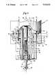
- FIG. 2is a partially cut away side view of a tool holder and tool.
- FIG. 1illustrates a robotic device 10 having a tool assembly 12 attached to an arm 14.
- the robotic deviceincludes means 16 for rotational movement, means 18 for lateral extension, and means 22 for longitudinal extension which, in conjunction, manipulate the spacial positioning of the tool assembly.
- the robotic device as shownis merely representive of robotic means adapted for positioning a tool in three dimensional space and to be programmed to move such a tool through a predetermined path.
- the tool assemblyis attached to a distal end 24 of the arm and provides means for performing work on an object 25.
- the means for performing workis a deburring tool 26 having a cutting surface 28 and the object includes an edge 32 to be deburred and structure 34 which extends adjacent to the edge to be deburred.
- the adjacent structurepresents an obstruction that prevents the use of tool assemblies which are canted or angled relative to the longitudinal axis.
- the edge and the adjacent structureare representative of an object to be deburred that presents a working path for the tool assembly which limits or does not permit lateral movement of the tool assembly.
- the tool assemblyincludes means 36 to provide compliance to the tool.
- Compliant means 36permits the cutting surface of the tool to move relative to the edge to be deburred to accommodate inaccuracies in the programmed path relative to the edge.
- the complianceis directed axially relative to a longitudinal axis 38 of the tool assembly.
- the axially compliant meansalso permits the working force provided to the tool to remain constant as the cutting surface moves along the surface being worked upon. In this way, errors in the programmed path of the tool and unanticipated fluctuations in the edge are accommodated without a significant variation in cutting force and without a need for lateral movement of the cutting surface.
- the axially compliant meansis illustrated in more detail in FIG. 2.
- the axially compliant meansis disposed between the tool and the drive means for the tool.
- the toolis attached to the axially compliant means by a collet assembly 42 which is attached to a tool shaft 44.
- the tool shafthas an internally splined surface 46 which is engaged with an externally splined surface 48 of the drive shaft.
- the drive shaftis engaged with the tool drive means.
- engagement between the splined surfaces of the tool shaft and drive shaftprovide means to transfer rotational force from the drive means through the drive shaft and the tool shaft and to the tool.
- the collet assemblyprovides means to attach the tool to the axially compliant means and the tool shaft.
- the splined surface of the tool shaftpermits relative axial motion between the tool shaft and drive shaft.
- the tool shaft, and thereby the collet assembly and tool attached to the tool shaft,are axially restrained relative to the axially compliant means by engagement of the tool shaft with a sleeve 52.
- the tool shaftincludes a radial bearing surface 54 which is engaged with a radial bearing assembly 56.
- the radial bearing assemblyis axially retained to the sleeve by a cylindrical cutout 58 in the sleeve and a snap-ring 62.
- the radial bearing assemblypermits relative rotational motion between the tool shaft and the sleeve while axially retaining the tool shaft relative to the sleeve.
- the sleeveis hollow and extends longitudinally from the tool drive means to the tool.
- the sleeveincludes an axially inward portion 64 slidably engaged with the tool drive means, a flange 66 extending radially outward from the sleeve, a linear bearing surface 68, and a plurality of circumferentially oriented O-ring slots 72.
- the flangeincludes an outer end 74 which is slidably engaged with a base 76.
- the linear bearing surfaceis slidably engaged with a linear bearing 78.
- the baseincludes a flange contact surface 82, an axial stop 84, and a circumferential cutout 86 adapted to fit the linear bearing.
- the linear bearingis retained within the circumferential cutout by a snap- ring 88.
- the linear bearingprovides means to permit axially directed sliding motion between the sleeve and the base.
- the basealso includes a base flowpath 92 and a plurality of circumferentially oriented O-ring slots 94. The base is attached to a mating surface 96 of the tool drive means.
- the tool drive meansincludes means for generating a rotational force (not shown), a sleeve contact surface 98, a high pressure fluid flow passage 102, and a low pressure fluid flow passage 104.
- the low pressure fluid flow passageis in fluid communication with the base flow passage.
- the axial separation between the flange and the mating surface and the radial separation between the sleeve and the basedefine a first annular sealed cavity 106.
- the first sealed cavityis in fluid communication with the high pressure flow passage of the tool drive means.
- Sealing means for the first cavityis provided by engagement between a flange O-ring 108 and the flange contact surface, engagement between a sleeve O-ring and 112 the sleeve contact surface, and engagement between a first base O-ring 114 and the mating surface.
- the axial separation between the flange and the axial stop and the radial separation between the sleeve and the flange contact surfacedefines a second sealed cavity 116.
- the second sealed cavityis in fluid communication with the base flow passage.
- Sealing means for the second sealed cavityprovided by the engagement of the flange O-ring with the flange contact surface and engagement between a second base O-ring 118 and the sleeve.
- sealing means for the juncture between the base flow passage and the low pressure flow passageis provided by the engagement by the first base O-ring and the mating surface and engagement by a third base O-ring 120 and the mating surface.
- the drive meansDuring operation, the drive means generates a rotational force which is transferred sequentially to the drive shaft, to the tool shaft, to the collet assembly, and to the tool. Rotation of the tool provides for relative motion between the cutting surface of the tool and the edge of the object being worked upon.
- the differential pressure between the two sealed cavitiesprovides an axially directed force and defines means to apply force to the tool. This differential pressure is the difference between the pressure P 1 of the fluid flowing through the high pressure flow passage into the first sealed cavity and the pressure P 2 of the fluid flowing through the low pressure flow passage, through the base flow passage, and into the second sealed cavity (P 2 -P 1 ).
- the pressure P 1 of the first sealed cavitygenerates an axially directed force equal to the pressure P 1 multiplied by the surface area of the flange bordering the first sealed cavity ( ⁇ (R 2 -R 1 ) 2 ).
- An oppositely directed axially forceis provided by the pressure P 2 of the second sealed cavity upon the surface of the flange bordering the second sealed cavity. The difference between these two axially directed forces is the working force upon the tool.
- the axially compliant meansprovides a constant axially directed work force between the cutting surface of the tool and the edge.
- the constant work forceis maintained by permitting axial movement of the tool relative to the tool assembly.
- the axial motionis accomplished by the sliding of the sleeve relative to the tool drive means, the base, and the linear bearing.
- the axially directed work forceis maintained constant by monitoring the pressure P 1 and P 2 and adjusting P 1 and P 2 to maintain a constant differential pressure between the two sealed cavities.
- a suggested means of maintaining a constant pressure differentialis to provide pressure accumulators (not shown) as the sources of pressures P 1 and P 2 and which have a large volume relative to the volume of the sealed cavities. In this way changes in the volume of the sealed cavities will have neglible effects on the pressure within the accumulators and thereby the pressure within the sealed cavities.
- Another means to maintain a constant pressure differentialis to monitor the pressure within the cavities and to adjust the pressures P 1 and P 2 in response to changes in pressure within the sealed cavities.
- the sleeveis initially positioned such that it may travel axially a distance A to accommodate obstructions along the edge and a distance B to accommodate unexpected separations between the cutting surface and the edge.
- the flangewill be initially positioned centrally between the axial stop of the base and the mating surface. In this position, the size of the first sealed cavity is equal to the size of the second sealed cavity and the axial distance A is equal to the axial distance B.
- the axial compliant meansis disposed between the tool and the drive means for the tools. This arrangement eliminates the drive means from the compliant or moving parts of the tool assembly. Limiting the axially compliant parts to the tool, collet, tool shaft, radial bearing, and sleeve minimizes the weight of the axially compliant parts of the tool assembly and thereby increases the sensitivity of the tool. The increased sensitivity is a result of the reduced momentum (mass ⁇ velocity 2 ) of the compliant parts. The increased sensitivity permits the tool to react responsively to deviations in the path and/or edge being cut.
Landscapes
- Engineering & Computer Science (AREA)
- Mechanical Engineering (AREA)
- Manipulator (AREA)
Abstract
Description
Claims (19)
Priority Applications (1)
| Application Number | Priority Date | Filing Date | Title |
|---|---|---|---|
| US07/952,429US5312212A (en) | 1992-09-28 | 1992-09-28 | Axially compliant tool holder |
Applications Claiming Priority (1)
| Application Number | Priority Date | Filing Date | Title |
|---|---|---|---|
| US07/952,429US5312212A (en) | 1992-09-28 | 1992-09-28 | Axially compliant tool holder |
Publications (1)
| Publication Number | Publication Date |
|---|---|
| US5312212Atrue US5312212A (en) | 1994-05-17 |
Family
ID=25492903
Family Applications (1)
| Application Number | Title | Priority Date | Filing Date |
|---|---|---|---|
| US07/952,429Expired - Fee RelatedUS5312212A (en) | 1992-09-28 | 1992-09-28 | Axially compliant tool holder |
Country Status (1)
| Country | Link |
|---|---|
| US (1) | US5312212A (en) |
Cited By (34)
| Publication number | Priority date | Publication date | Assignee | Title |
|---|---|---|---|---|
| US5396714A (en)* | 1993-12-15 | 1995-03-14 | Carnegie Mellon University | Apparatus for assembly of axisymmetric and non-axisymmetric rigid parts |
| US5548194A (en)* | 1993-06-08 | 1996-08-20 | Fanuc Ltd. | Control method and control device for a deburring robot |
| US6086294A (en)* | 1999-03-19 | 2000-07-11 | Fanuc Robotics North America Inc. | Robotic deflashing of plastics with cutter guidance |
| US6102636A (en)* | 1996-05-21 | 2000-08-15 | Geise; Samuel C. | Hydraulically powered spindle for working metals and composite materials |
| US6132368A (en)* | 1996-12-12 | 2000-10-17 | Intuitive Surgical, Inc. | Multi-component telepresence system and method |
| US6193591B1 (en)* | 1999-11-24 | 2001-02-27 | Ten Cate Enbi International Bv | Loading system and collect assembly for grinding a workpiece |
| US6309152B1 (en)* | 1999-02-25 | 2001-10-30 | Proesl Johanna | Tool unit with cutter head |
| US6331181B1 (en) | 1998-12-08 | 2001-12-18 | Intuitive Surgical, Inc. | Surgical robotic tools, data architecture, and use |
| US6620173B2 (en) | 1998-12-08 | 2003-09-16 | Intuitive Surgical, Inc. | Method for introducing an end effector to a surgical site in minimally invasive surgery |
| US6649220B1 (en) | 1998-10-14 | 2003-11-18 | Wallace F. Krueger | Compliance mechanism |
| US20040054355A1 (en)* | 2001-05-31 | 2004-03-18 | Intuitive Surgical, Inc. | Tool guide and method for introducing an end effector to a surgical site in minimally invasive surgery |
| US6783524B2 (en) | 2001-04-19 | 2004-08-31 | Intuitive Surgical, Inc. | Robotic surgical tool with ultrasound cauterizing and cutting instrument |
| US6840938B1 (en) | 2000-12-29 | 2005-01-11 | Intuitive Surgical, Inc. | Bipolar cauterizing instrument |
| US20050019123A1 (en)* | 2003-07-25 | 2005-01-27 | Lawson Douglas K. | Deburring tool |
| US20050180829A1 (en)* | 2003-07-25 | 2005-08-18 | Lawson Douglas K. | Pneumatically driven deburring tool having an articulated air joint |
| US20050251110A1 (en)* | 2004-05-04 | 2005-11-10 | Intuitive Surgical, Inc. | Tool grip calibration for robotic surgery |
| US20060039768A1 (en)* | 2004-08-17 | 2006-02-23 | Fanuc Ltd | Finishing machine |
| US20060065358A1 (en)* | 2002-09-25 | 2006-03-30 | Cupp John P | Method and apparatus for substantially simultaneously cleaning internal and external regions of plastic frames |
| US7073423B2 (en) | 2003-09-17 | 2006-07-11 | Robotic Production Technology, Inc. | Compliance device for trimming a workpiece |
| US20070005045A1 (en)* | 2005-06-30 | 2007-01-04 | Intuitive Surgical Inc. | Indicator for tool state and communication in multi-arm robotic telesurgery |
| US20070239203A1 (en)* | 2002-12-06 | 2007-10-11 | Intuitive Surgical, Inc. | Flexible wrist for surgical tool |
| US20080005885A1 (en)* | 2004-12-16 | 2008-01-10 | Richard Bergner Verbindungstechnik Gmbh & Co. Kg | Compensating unit for a tool unit and method for inserting an element into a workpiece |
| US20130192059A1 (en)* | 2012-01-30 | 2013-08-01 | Heinrich Steger | Machining apparatus for grinding, milling, polishing or the like of a dental workpiece |
| US8894634B2 (en) | 2005-06-30 | 2014-11-25 | Intuitive Surgical Operations, Inc. | Indicator for tool state and communication in multi-arm robotic telesurgery |
| US8911428B2 (en) | 2001-06-29 | 2014-12-16 | Intuitive Surgical Operations, Inc. | Apparatus for pitch and yaw rotation |
| US8998930B2 (en) | 2005-12-20 | 2015-04-07 | Intuitive Surgical Operations, Inc. | Disposable sterile surgical adaptor |
| US8998799B2 (en) | 1996-12-12 | 2015-04-07 | Intuitive Surgical Operations, Inc. | Sterile surgical adaptor |
| US9005112B2 (en) | 2001-06-29 | 2015-04-14 | Intuitive Surgical Operations, Inc. | Articulate and swapable endoscope for a surgical robot |
| US9320568B2 (en) | 1997-11-21 | 2016-04-26 | Intuitive Surgical Operations, Inc. | Sterile surgical drape |
| US9439732B2 (en) | 1996-12-12 | 2016-09-13 | Intuitive Surgical Operations, Inc. | Instrument interface of a robotic surgical system |
| US9532849B2 (en) | 1997-11-21 | 2017-01-03 | Intuitive Surgical Operations, Inc. | Surgical accessory clamp and system |
| US20180264560A1 (en)* | 2017-03-14 | 2018-09-20 | Kreuz Co., Ltd. | Chamfering tool, tool support set and chamfering system |
| US10625423B2 (en) | 2016-10-19 | 2020-04-21 | Component Aerospace Singapore Pte. Ltd. | Method and apparatus for facilitating part verification |
| US10926340B2 (en)* | 2018-06-19 | 2021-02-23 | Kawasaki Jukogyo Kabushiki Kaisha | Chamfering device and chamfering method |
Citations (15)
| Publication number | Priority date | Publication date | Assignee | Title |
|---|---|---|---|---|
| US3208311A (en)* | 1963-04-04 | 1965-09-28 | Cross Co | Tool detector |
| US3254548A (en)* | 1964-04-13 | 1966-06-07 | Briney Mfg Co | Boring quill |
| US3299783A (en)* | 1963-07-05 | 1967-01-24 | Mach Outiles S E C M O Soc D E | Fluid operated machine tool spindle |
| US3640633A (en)* | 1969-08-28 | 1972-02-08 | Richard C Gersch | Adjustable boring quill assembly |
| US3884590A (en)* | 1974-05-22 | 1975-05-20 | Lamb Co F Jos | Adjustable dual tool boring bar |
| US4332066A (en)* | 1980-01-07 | 1982-06-01 | General Dynamics Corporation | Compliance mechanism |
| US4412465A (en)* | 1981-12-07 | 1983-11-01 | Lamb Technicon Corp. | Tool compensator |
| JPS60249519A (en)* | 1984-05-26 | 1985-12-10 | Daikin Ind Ltd | Robot tool holder |
| US4637775A (en)* | 1983-12-15 | 1987-01-20 | Mitsubishi Denki Kabushiki Kaisha | Industrial robot device |
| US4784540A (en)* | 1985-09-23 | 1988-11-15 | Njal Underhaug | Rotary and yieldable drive means for a tool |
| US4860500A (en)* | 1987-08-27 | 1989-08-29 | General Electric Company | Passive actuator to maintain a constant normal cutting force during robotic deburring |
| DD276647A1 (en)* | 1988-11-02 | 1990-03-07 | Verkehrswesen Forsch Inst | OVERLOAD PROTECTION DEVICE FOR WELDER MANIPULATOR, ESPECIALLY ROBOT |
| US4991274A (en)* | 1988-12-19 | 1991-02-12 | Ray Fortier | Tool holder for burnishing cutter |
| US4993896A (en)* | 1988-12-13 | 1991-02-19 | General Electric Company | Edge contouring system |
| US5146670A (en)* | 1985-04-24 | 1992-09-15 | The Boeing Company | Profiling and deburring of workpieces |
- 1992
- 1992-09-28USUS07/952,429patent/US5312212A/ennot_activeExpired - Fee Related
Patent Citations (15)
| Publication number | Priority date | Publication date | Assignee | Title |
|---|---|---|---|---|
| US3208311A (en)* | 1963-04-04 | 1965-09-28 | Cross Co | Tool detector |
| US3299783A (en)* | 1963-07-05 | 1967-01-24 | Mach Outiles S E C M O Soc D E | Fluid operated machine tool spindle |
| US3254548A (en)* | 1964-04-13 | 1966-06-07 | Briney Mfg Co | Boring quill |
| US3640633A (en)* | 1969-08-28 | 1972-02-08 | Richard C Gersch | Adjustable boring quill assembly |
| US3884590A (en)* | 1974-05-22 | 1975-05-20 | Lamb Co F Jos | Adjustable dual tool boring bar |
| US4332066A (en)* | 1980-01-07 | 1982-06-01 | General Dynamics Corporation | Compliance mechanism |
| US4412465A (en)* | 1981-12-07 | 1983-11-01 | Lamb Technicon Corp. | Tool compensator |
| US4637775A (en)* | 1983-12-15 | 1987-01-20 | Mitsubishi Denki Kabushiki Kaisha | Industrial robot device |
| JPS60249519A (en)* | 1984-05-26 | 1985-12-10 | Daikin Ind Ltd | Robot tool holder |
| US5146670A (en)* | 1985-04-24 | 1992-09-15 | The Boeing Company | Profiling and deburring of workpieces |
| US4784540A (en)* | 1985-09-23 | 1988-11-15 | Njal Underhaug | Rotary and yieldable drive means for a tool |
| US4860500A (en)* | 1987-08-27 | 1989-08-29 | General Electric Company | Passive actuator to maintain a constant normal cutting force during robotic deburring |
| DD276647A1 (en)* | 1988-11-02 | 1990-03-07 | Verkehrswesen Forsch Inst | OVERLOAD PROTECTION DEVICE FOR WELDER MANIPULATOR, ESPECIALLY ROBOT |
| US4993896A (en)* | 1988-12-13 | 1991-02-19 | General Electric Company | Edge contouring system |
| US4991274A (en)* | 1988-12-19 | 1991-02-12 | Ray Fortier | Tool holder for burnishing cutter |
Non-Patent Citations (6)
| Title |
|---|
| Harper Surface Finishing Systems Multi Axis Smart Flexible Finishing Cell Form MM 1.* |
| Harper Surface Finishing Systems-"Multi-Axis Smart Flexible Finishing Cell" Form MM-1. |
| Kappa One K 1, Yamaha Polishing Robot, Yamaha Corporation, Industrial Engineering Division, 6 pages.* |
| Kappa-One K-1, Yamaha Polishing Robot, Yamaha Corporation, Industrial Engineering Division, 6 pages. |
| Z 1, Yamaha Deburring Robot, Yamaha Corporation, 2 pages.* |
| Z-1, Yamaha Deburring Robot, Yamaha Corporation, 2 pages. |
Cited By (93)
| Publication number | Priority date | Publication date | Assignee | Title |
|---|---|---|---|---|
| US5548194A (en)* | 1993-06-08 | 1996-08-20 | Fanuc Ltd. | Control method and control device for a deburring robot |
| US5396714A (en)* | 1993-12-15 | 1995-03-14 | Carnegie Mellon University | Apparatus for assembly of axisymmetric and non-axisymmetric rigid parts |
| US6102636A (en)* | 1996-05-21 | 2000-08-15 | Geise; Samuel C. | Hydraulically powered spindle for working metals and composite materials |
| US9439732B2 (en) | 1996-12-12 | 2016-09-13 | Intuitive Surgical Operations, Inc. | Instrument interface of a robotic surgical system |
| US8998799B2 (en) | 1996-12-12 | 2015-04-07 | Intuitive Surgical Operations, Inc. | Sterile surgical adaptor |
| US9795453B2 (en) | 1996-12-12 | 2017-10-24 | Intuitive Surgical Operations, Inc. | Surgical robotic tools, data architecture, and use |
| US9724163B2 (en) | 1996-12-12 | 2017-08-08 | Intuitive Surgical Operations, Inc. | Disposable sterile surgical adaptor |
| US9949802B2 (en) | 1996-12-12 | 2018-04-24 | Intuitive Surgical Operations, Inc. | Multi-component telepresence system and method |
| US20050021050A1 (en)* | 1996-12-12 | 2005-01-27 | Intuitive Surgical, Inc. | Multi-component telepresence system and method |
| US6346072B1 (en) | 1996-12-12 | 2002-02-12 | Intuitive Surgical, Inc. | Multi-component telepresence system and method |
| US6132368A (en)* | 1996-12-12 | 2000-10-17 | Intuitive Surgical, Inc. | Multi-component telepresence system and method |
| US8608773B2 (en) | 1996-12-12 | 2013-12-17 | Intuitive Surgical Operations, Inc. | Surgical robotic tools, data architecture, and use |
| US20110066161A1 (en)* | 1996-12-12 | 2011-03-17 | Intuitive Surgical Operations, Inc. | Multi-Component Telepresence System and Method |
| US20110028990A1 (en)* | 1996-12-12 | 2011-02-03 | Intuitive Surgical Operations, Inc. | Multi-Component Telepresence System and Method |
| US7819885B2 (en) | 1996-12-12 | 2010-10-26 | Intuitive Surgical Operations, Inc. | Multi-component telepresence system and method |
| US7357774B2 (en) | 1996-12-12 | 2008-04-15 | Intuitive Surgical Inc. | Multi-component telepresence system and method |
| US20070012135A1 (en)* | 1996-12-12 | 2007-01-18 | Intuitive Surgical Inc. | Surgical robotic tools, data architecture, and use |
| US6866671B2 (en) | 1996-12-12 | 2005-03-15 | Intuitive Surgical, Inc. | Surgical robotic tools, data architecture, and use |
| US9532849B2 (en) | 1997-11-21 | 2017-01-03 | Intuitive Surgical Operations, Inc. | Surgical accessory clamp and system |
| US9320568B2 (en) | 1997-11-21 | 2016-04-26 | Intuitive Surgical Operations, Inc. | Sterile surgical drape |
| US6649220B1 (en) | 1998-10-14 | 2003-11-18 | Wallace F. Krueger | Compliance mechanism |
| US7048745B2 (en) | 1998-12-08 | 2006-05-23 | Intuitive Surgical | Surgical robotic tools, data architecture, and use |
| US6620173B2 (en) | 1998-12-08 | 2003-09-16 | Intuitive Surgical, Inc. | Method for introducing an end effector to a surgical site in minimally invasive surgery |
| US8758352B2 (en) | 1998-12-08 | 2014-06-24 | Intuitive Surgical Operations, Inc. | Mechanical actuator interface system for robotic surgical tools |
| US20030083673A1 (en)* | 1998-12-08 | 2003-05-01 | Intuitive Surgical, Inc. | Mechanical actuator interface system for robotic surgical tools |
| US8142447B2 (en) | 1998-12-08 | 2012-03-27 | Intuitive Surgical Operations Inc. | Mechanical actuator interface system for robotic surgical tools |
| US20020032452A1 (en)* | 1998-12-08 | 2002-03-14 | Tierney Michael J. | Surgical robotic tools, data architecture, and use |
| US7524320B2 (en) | 1998-12-08 | 2009-04-28 | Intuitive Surgical, Inc. | Mechanical actuator interface system for robotic surgical tools |
| US6491701B2 (en) | 1998-12-08 | 2002-12-10 | Intuitive Surgical, Inc. | Mechanical actuator interface system for robotic surgical tools |
| US6331181B1 (en) | 1998-12-08 | 2001-12-18 | Intuitive Surgical, Inc. | Surgical robotic tools, data architecture, and use |
| US6309152B1 (en)* | 1999-02-25 | 2001-10-30 | Proesl Johanna | Tool unit with cutter head |
| US6086294A (en)* | 1999-03-19 | 2000-07-11 | Fanuc Robotics North America Inc. | Robotic deflashing of plastics with cutter guidance |
| US6193591B1 (en)* | 1999-11-24 | 2001-02-27 | Ten Cate Enbi International Bv | Loading system and collect assembly for grinding a workpiece |
| WO2001038045A1 (en)* | 1999-11-24 | 2001-05-31 | Ten Cate Enbi International Bv | Loading system and collet assembly for grinding a workpiece |
| US20050240178A1 (en)* | 2000-12-29 | 2005-10-27 | Intuitive Surgical, Inc. | Bipolar cauterizing instrument |
| US6840938B1 (en) | 2000-12-29 | 2005-01-11 | Intuitive Surgical, Inc. | Bipolar cauterizing instrument |
| US7422592B2 (en) | 2000-12-29 | 2008-09-09 | Intuitive Surgical, Inc. | Bipolar cauterizing instrument |
| US20070123855A1 (en)* | 2000-12-29 | 2007-05-31 | Intuitive Surgical Inc. | Bipolar cauterizing instrument |
| US6783524B2 (en) | 2001-04-19 | 2004-08-31 | Intuitive Surgical, Inc. | Robotic surgical tool with ultrasound cauterizing and cutting instrument |
| US20050021018A1 (en)* | 2001-04-19 | 2005-01-27 | Intuitive Surgical, Inc., A Delaware Corporation | Robotic surgical tool with ultrasound cauterizing and cutting instrument |
| US20040054355A1 (en)* | 2001-05-31 | 2004-03-18 | Intuitive Surgical, Inc. | Tool guide and method for introducing an end effector to a surgical site in minimally invasive surgery |
| US10506920B2 (en) | 2001-06-29 | 2019-12-17 | Intuitive Surgical Operations, Inc. | Articulate and swappable endoscope for a surgical robot |
| US8911428B2 (en) | 2001-06-29 | 2014-12-16 | Intuitive Surgical Operations, Inc. | Apparatus for pitch and yaw rotation |
| US10105128B2 (en) | 2001-06-29 | 2018-10-23 | Intuitive Surgical Operations, Inc. | Apparatus for pitch and yaw rotation |
| US9730572B2 (en) | 2001-06-29 | 2017-08-15 | Intuitive Surgical Operations, Inc. | Articulate and swappable endoscope for a surgical robot |
| US9005112B2 (en) | 2001-06-29 | 2015-04-14 | Intuitive Surgical Operations, Inc. | Articulate and swapable endoscope for a surgical robot |
| US9717486B2 (en) | 2001-06-29 | 2017-08-01 | Intuitive Surgical Operations, Inc. | Apparatus for pitch and yaw rotation |
| US11051794B2 (en) | 2001-06-29 | 2021-07-06 | Intuitive Surgical Operations, Inc. | Apparatus for pitch and yaw rotation |
| US20060065358A1 (en)* | 2002-09-25 | 2006-03-30 | Cupp John P | Method and apparatus for substantially simultaneously cleaning internal and external regions of plastic frames |
| US8690908B2 (en) | 2002-12-06 | 2014-04-08 | Intuitive Surgical Operations, Inc. | Flexible wrist for surgical tool |
| US8337521B2 (en) | 2002-12-06 | 2012-12-25 | Intuitive Surgical Operations, Inc. | Flexible wrist for surgical tool |
| US9623563B2 (en) | 2002-12-06 | 2017-04-18 | Intuitive Surgical Operations, Inc. | Tool grip calibration for robotic surgery |
| US11633241B2 (en) | 2002-12-06 | 2023-04-25 | Intuitive Surgical Operations, Inc. | Flexible wrist for surgical tool |
| US9585641B2 (en) | 2002-12-06 | 2017-03-07 | Intuitive Surgical Operations, Inc. | Flexible wrist for surgical tool |
| US20110125166A1 (en)* | 2002-12-06 | 2011-05-26 | Intuitive Surgical Operations, Inc. | Flexible Wrist for Surgical Tool |
| US7862580B2 (en) | 2002-12-06 | 2011-01-04 | Intuitive Surgical Operations, Inc. | Flexible wrist for surgical tool |
| US8790243B2 (en) | 2002-12-06 | 2014-07-29 | Intuitive Surgical Operations, Inc. | Flexible wrist for surgical tool |
| US20070239203A1 (en)* | 2002-12-06 | 2007-10-11 | Intuitive Surgical, Inc. | Flexible wrist for surgical tool |
| US10524868B2 (en) | 2002-12-06 | 2020-01-07 | Intuitive Surgical Operations, Inc. | Flexible wrist for surgical tool |
| US9095317B2 (en) | 2002-12-06 | 2015-08-04 | Intuitive Surgical Operations, Inc. | Flexible wrist for surgical tool |
| US6974286B2 (en)* | 2003-07-25 | 2005-12-13 | Ati Industrial Automation, Inc. | Deburring tool |
| US20050019123A1 (en)* | 2003-07-25 | 2005-01-27 | Lawson Douglas K. | Deburring tool |
| US7137763B2 (en)* | 2003-07-25 | 2006-11-21 | Ati Industrial Automation, Inc. | Pneumatically driven deburring tool having an articulated air joint |
| US20050180829A1 (en)* | 2003-07-25 | 2005-08-18 | Lawson Douglas K. | Pneumatically driven deburring tool having an articulated air joint |
| US7073423B2 (en) | 2003-09-17 | 2006-07-11 | Robotic Production Technology, Inc. | Compliance device for trimming a workpiece |
| US9317651B2 (en) | 2004-05-04 | 2016-04-19 | Intuitive Surgical Operations, Inc. | Tool grip calibration for robotic surgery |
| US9085083B2 (en) | 2004-05-04 | 2015-07-21 | Intuitive Surgical Operations, Inc. | Tool grip calibration for robotic surgery |
| US20080114494A1 (en)* | 2004-05-04 | 2008-05-15 | Intuitive Surgical, Inc. | Tool grip calibration for robotic surgery |
| US9872737B2 (en) | 2004-05-04 | 2018-01-23 | Intuitive Surgical Operations, Inc. | Tool grip calibration for robotic surgery |
| US10595946B2 (en) | 2004-05-04 | 2020-03-24 | Intuitive Surgical Operations, Inc. | Tool grip calibration for robotic surgery |
| US20050251110A1 (en)* | 2004-05-04 | 2005-11-10 | Intuitive Surgical, Inc. | Tool grip calibration for robotic surgery |
| US8452447B2 (en) | 2004-05-04 | 2013-05-28 | Intuitive Surgical Operations, Inc. | Tool grip calibration for robotic surgery |
| US7386365B2 (en) | 2004-05-04 | 2008-06-10 | Intuitive Surgical, Inc. | Tool grip calibration for robotic surgery |
| US7534077B2 (en)* | 2004-08-17 | 2009-05-19 | Fanuc Ltd | Finishing machine |
| US20060039768A1 (en)* | 2004-08-17 | 2006-02-23 | Fanuc Ltd | Finishing machine |
| US7685700B2 (en)* | 2004-12-16 | 2010-03-30 | Richard Bergner Verbindungstechnik Gmbh & Co. Kg | Compensating unit for a tool unit and method for inserting an element into a workpiece |
| US20080005885A1 (en)* | 2004-12-16 | 2008-01-10 | Richard Bergner Verbindungstechnik Gmbh & Co. Kg | Compensating unit for a tool unit and method for inserting an element into a workpiece |
| US11723735B2 (en) | 2005-06-30 | 2023-08-15 | Intuitive Surgical Operations, Inc. | Indicator for tool state and communication in multi-arm robotic telesurgery |
| US12201388B2 (en) | 2005-06-30 | 2025-01-21 | Intuitive Surgical Operations, Inc. | Indicator for tool state and communication in multi-arm robotic telesurgery |
| US11337765B2 (en) | 2005-06-30 | 2022-05-24 | Intuitive Surgical Operations, Inc. | Indicator for tool state and communication in multi-arm robotic telesurgery |
| US10258416B2 (en) | 2005-06-30 | 2019-04-16 | Intuitive Surgical Operations, Inc. | Indicator for tool state and communication in multiarm robotic telesurgery |
| US10335242B2 (en) | 2005-06-30 | 2019-07-02 | Intuitive Surgical Operations, Inc. | Indicator for tool state and communication in multi-arm robotic telesurgery |
| US9259276B2 (en) | 2005-06-30 | 2016-02-16 | Intuitive Surgical Operations, Inc. | Indicator for tool state and communication in multiarm telesurgery |
| US8894634B2 (en) | 2005-06-30 | 2014-11-25 | Intuitive Surgical Operations, Inc. | Indicator for tool state and communication in multi-arm robotic telesurgery |
| US20070005045A1 (en)* | 2005-06-30 | 2007-01-04 | Intuitive Surgical Inc. | Indicator for tool state and communication in multi-arm robotic telesurgery |
| US8100133B2 (en) | 2005-06-30 | 2012-01-24 | Intuitive Surgical Operations | Indicator for tool state and communication in multi-arm robotic telesurgery and method of use |
| US8998930B2 (en) | 2005-12-20 | 2015-04-07 | Intuitive Surgical Operations, Inc. | Disposable sterile surgical adaptor |
| US9009946B2 (en)* | 2012-01-30 | 2015-04-21 | Heinrich Steger | Machining apparatus for grinding, milling, polishing or the like of a dental workpiece |
| US20130192059A1 (en)* | 2012-01-30 | 2013-08-01 | Heinrich Steger | Machining apparatus for grinding, milling, polishing or the like of a dental workpiece |
| US10625423B2 (en) | 2016-10-19 | 2020-04-21 | Component Aerospace Singapore Pte. Ltd. | Method and apparatus for facilitating part verification |
| US10213847B2 (en)* | 2017-03-14 | 2019-02-26 | Kreuz Co., Ltd. | Chamfering tool, tool support set and chamfering system |
| US20180264560A1 (en)* | 2017-03-14 | 2018-09-20 | Kreuz Co., Ltd. | Chamfering tool, tool support set and chamfering system |
| US10926340B2 (en)* | 2018-06-19 | 2021-02-23 | Kawasaki Jukogyo Kabushiki Kaisha | Chamfering device and chamfering method |
Similar Documents
| Publication | Publication Date | Title |
|---|---|---|
| US5312212A (en) | Axially compliant tool holder | |
| EP0241506B1 (en) | A device in a rotating drive means for a tool | |
| JPH09503447A (en) | Machine tool equipment and its linear motion truck | |
| KR102662204B1 (en) | Machine tool | |
| EP0883468B1 (en) | A production positioning system | |
| CA2335396A1 (en) | Tool compliance device and method | |
| US4828437A (en) | Apparatus for supporting a workpiece | |
| EP0415374B1 (en) | Feed mechanism with a sliding member guided by a hydrostatic bearing | |
| US6609441B1 (en) | Indexing device | |
| Kramer et al. | Robotic deburring | |
| EP0994763B1 (en) | Grinding machine spindle | |
| US4860500A (en) | Passive actuator to maintain a constant normal cutting force during robotic deburring | |
| CN213945706U (en) | Inner hole clamping device | |
| US5277526A (en) | Apparatus with floating tool for drilling, boring, flaring and the like at a set depth using jigs | |
| ATE68894T1 (en) | METHOD OF CONTROLLING THE THREE-DIMENSIONAL MOVEMENT OF A ROBOT RELATIVE TO A WORKPIECE ATTACHED TO A WORKPIECE. | |
| EP0537546A1 (en) | Operating head for automatic machine tools with chuck support angular locking devices | |
| JP4978912B2 (en) | Work machine | |
| Hanson et al. | Reducing cutting force induced bore cylindricity errors by learning control and variable depth of cut machining | |
| KR20240005758A (en) | pneumatic linear actuator | |
| KR20230111243A (en) | Assemblies and devices for machining machine parts | |
| JP3788539B2 (en) | Cycle processing equipment for free-curved members | |
| CZ308657B6 (en) | Robotic machining head | |
| JP2641898B2 (en) | Processing equipment | |
| JPS60221240A (en) | Feed device | |
| US4209180A (en) | Self-centering work holding and positioning fixture for machine tools |
Legal Events
| Date | Code | Title | Description |
|---|---|---|---|
| AS | Assignment | Owner name:UNITED TECHNOLOGIES CORPORATION, CONNECTICUT Free format text:ASSIGNMENT OF ASSIGNORS INTEREST.;ASSIGNOR:NAUMEC, JOHN R.;REEL/FRAME:006310/0927 Effective date:19920925 | |
| FEPP | Fee payment procedure | Free format text:PAYOR NUMBER ASSIGNED (ORIGINAL EVENT CODE: ASPN); ENTITY STATUS OF PATENT OWNER: LARGE ENTITY | |
| FPAY | Fee payment | Year of fee payment:4 | |
| REMI | Maintenance fee reminder mailed | ||
| LAPS | Lapse for failure to pay maintenance fees | ||
| STCH | Information on status: patent discontinuation | Free format text:PATENT EXPIRED DUE TO NONPAYMENT OF MAINTENANCE FEES UNDER 37 CFR 1.362 | |
| FP | Lapsed due to failure to pay maintenance fee | Effective date:20020517 | |
| AS | Assignment | Owner name:4077776 CANADA INC., CANADA Free format text:ASSIGNMENT OF ASSIGNORS INTEREST;ASSIGNOR:HOLDEN AMERICA INC.;REEL/FRAME:013678/0502 Effective date:20030201 | |
| AS | Assignment | Owner name:HOLDEN AMERICA INC., CANADA Free format text:ASSIGNMENT OF ASSIGNORS INTEREST;ASSIGNOR:4077776 CANADA INC.;REEL/FRAME:015177/0363 Effective date:20030201 | |
| FEPP | Fee payment procedure | Free format text:PAYER NUMBER DE-ASSIGNED (ORIGINAL EVENT CODE: RMPN); ENTITY STATUS OF PATENT OWNER: LARGE ENTITY |