US5310594A - Composite rigid insulation materials containing V-grooves - Google Patents
Composite rigid insulation materials containing V-groovesDownload PDFInfo
- Publication number
- US5310594A US5310594AUS07/884,871US88487192AUS5310594AUS 5310594 AUS5310594 AUS 5310594AUS 88487192 AUS88487192 AUS 88487192AUS 5310594 AUS5310594 AUS 5310594A
- Authority
- US
- United States
- Prior art keywords
- insulation
- composite
- grooves
- rigid
- flexible
- Prior art date
- Legal status (The legal status is an assumption and is not a legal conclusion. Google has not performed a legal analysis and makes no representation as to the accuracy of the status listed.)
- Expired - Fee Related
Links
- 239000002131composite materialSubstances0.000titleclaimsabstractdescription51
- 239000012774insulation materialSubstances0.000titleclaimsdescription14
- 239000000463materialSubstances0.000claimsabstractdescription99
- 238000009413insulationMethods0.000claimsabstractdescription78
- 239000011810insulating materialSubstances0.000claimsabstractdescription35
- 239000000853adhesiveSubstances0.000claimsdescription20
- 230000001070adhesive effectEffects0.000claimsdescription20
- 239000011490mineral woolSubstances0.000claimsdescription20
- 239000000835fiberSubstances0.000claimsdescription7
- 239000000919ceramicSubstances0.000claimsdescription6
- 229920005830Polyurethane FoamPolymers0.000claimsdescription4
- 239000011496polyurethane foamSubstances0.000claimsdescription4
- 239000006260foamSubstances0.000claimsdescription2
- 239000011248coating agentSubstances0.000claims3
- 238000000576coating methodMethods0.000claims3
- 239000011521glassSubstances0.000claims1
- 239000010410layerSubstances0.000description40
- 239000010451perliteSubstances0.000description6
- 235000019362perliteNutrition0.000description6
- 229910052500inorganic mineralInorganic materials0.000description5
- 239000011707mineralSubstances0.000description5
- 239000011494foam glassSubstances0.000description4
- 238000000034methodMethods0.000description4
- 230000004048modificationEffects0.000description4
- 238000012986modificationMethods0.000description4
- 239000011230binding agentSubstances0.000description3
- 238000009434installationMethods0.000description3
- 238000004519manufacturing processMethods0.000description3
- 230000002787reinforcementEffects0.000description3
- 230000006378damageEffects0.000description2
- 239000002023woodSubstances0.000description2
- 239000004820Pressure-sensitive adhesiveSubstances0.000description1
- 229910000746Structural steelInorganic materials0.000description1
- XAGFODPZIPBFFR-UHFFFAOYSA-NaluminiumChemical compound[Al]XAGFODPZIPBFFR-UHFFFAOYSA-N0.000description1
- 229910052782aluminiumInorganic materials0.000description1
- 239000010426asphaltSubstances0.000description1
- 230000015556catabolic processEffects0.000description1
- 230000001413cellular effectEffects0.000description1
- 239000007799corkSubstances0.000description1
- 238000006731degradation reactionMethods0.000description1
- 230000000694effectsEffects0.000description1
- 239000011888foilSubstances0.000description1
- -1for exampleSubstances0.000description1
- 239000004519greaseSubstances0.000description1
- 238000010438heat treatmentMethods0.000description1
- 238000011065in-situ storageMethods0.000description1
- 239000002655kraft paperSubstances0.000description1
- 239000000123paperSubstances0.000description1
- 239000002984plastic foamSubstances0.000description1
- 229920006395saturated elastomerPolymers0.000description1
- 238000000926separation methodMethods0.000description1
- 238000007493shaping processMethods0.000description1
- 239000002356single layerSubstances0.000description1
- 238000003860storageMethods0.000description1
- 239000000126substanceSubstances0.000description1
- 229920001187thermosetting polymerPolymers0.000description1
Images


Classifications
- B—PERFORMING OPERATIONS; TRANSPORTING
- B32—LAYERED PRODUCTS
- B32B—LAYERED PRODUCTS, i.e. PRODUCTS BUILT-UP OF STRATA OF FLAT OR NON-FLAT, e.g. CELLULAR OR HONEYCOMB, FORM
- B32B3/00—Layered products comprising a layer with external or internal discontinuities or unevennesses, or a layer of non-planar shape; Layered products comprising a layer having particular features of form
- B32B3/26—Layered products comprising a layer with external or internal discontinuities or unevennesses, or a layer of non-planar shape; Layered products comprising a layer having particular features of form characterised by a particular shape of the outline of the cross-section of a continuous layer; characterised by a layer with cavities or internal voids ; characterised by an apertured layer
- B32B3/30—Layered products comprising a layer with external or internal discontinuities or unevennesses, or a layer of non-planar shape; Layered products comprising a layer having particular features of form characterised by a particular shape of the outline of the cross-section of a continuous layer; characterised by a layer with cavities or internal voids ; characterised by an apertured layer characterised by a layer formed with recesses or projections, e.g. hollows, grooves, protuberances, ribs
- B—PERFORMING OPERATIONS; TRANSPORTING
- B29—WORKING OF PLASTICS; WORKING OF SUBSTANCES IN A PLASTIC STATE IN GENERAL
- B29C—SHAPING OR JOINING OF PLASTICS; SHAPING OF MATERIAL IN A PLASTIC STATE, NOT OTHERWISE PROVIDED FOR; AFTER-TREATMENT OF THE SHAPED PRODUCTS, e.g. REPAIRING
- B29C44/00—Shaping by internal pressure generated in the material, e.g. swelling or foaming ; Producing porous or cellular expanded plastics articles
- B29C44/34—Auxiliary operations
- B29C44/56—After-treatment of articles, e.g. for altering the shape
- B29C44/5627—After-treatment of articles, e.g. for altering the shape by mechanical deformation, e.g. crushing, embossing, stretching
- B29C44/5654—Subdividing foamed articles to obtain particular surface properties, e.g. on multiple modules
- B—PERFORMING OPERATIONS; TRANSPORTING
- B29—WORKING OF PLASTICS; WORKING OF SUBSTANCES IN A PLASTIC STATE IN GENERAL
- B29C—SHAPING OR JOINING OF PLASTICS; SHAPING OF MATERIAL IN A PLASTIC STATE, NOT OTHERWISE PROVIDED FOR; AFTER-TREATMENT OF THE SHAPED PRODUCTS, e.g. REPAIRING
- B29C53/00—Shaping by bending, folding, twisting, straightening or flattening; Apparatus therefor
- B29C53/02—Bending or folding
- B29C53/04—Bending or folding of plates or sheets
- B29C53/06—Forming folding lines by pressing or scoring
- B29C53/063—Forming folding lines by pressing or scoring combined with folding
- B—PERFORMING OPERATIONS; TRANSPORTING
- B32—LAYERED PRODUCTS
- B32B—LAYERED PRODUCTS, i.e. PRODUCTS BUILT-UP OF STRATA OF FLAT OR NON-FLAT, e.g. CELLULAR OR HONEYCOMB, FORM
- B32B1/00—Layered products having a non-planar shape
- B32B1/08—Tubular products
- B—PERFORMING OPERATIONS; TRANSPORTING
- B32—LAYERED PRODUCTS
- B32B—LAYERED PRODUCTS, i.e. PRODUCTS BUILT-UP OF STRATA OF FLAT OR NON-FLAT, e.g. CELLULAR OR HONEYCOMB, FORM
- B32B19/00—Layered products comprising a layer of natural mineral fibres or particles, e.g. asbestos, mica
- B32B19/04—Layered products comprising a layer of natural mineral fibres or particles, e.g. asbestos, mica next to another layer of the same or of a different material
- B32B19/047—Layered products comprising a layer of natural mineral fibres or particles, e.g. asbestos, mica next to another layer of the same or of a different material of foam
- B—PERFORMING OPERATIONS; TRANSPORTING
- B32—LAYERED PRODUCTS
- B32B—LAYERED PRODUCTS, i.e. PRODUCTS BUILT-UP OF STRATA OF FLAT OR NON-FLAT, e.g. CELLULAR OR HONEYCOMB, FORM
- B32B19/00—Layered products comprising a layer of natural mineral fibres or particles, e.g. asbestos, mica
- B32B19/06—Layered products comprising a layer of natural mineral fibres or particles, e.g. asbestos, mica next to a fibrous or filamentary layer
- B—PERFORMING OPERATIONS; TRANSPORTING
- B32—LAYERED PRODUCTS
- B32B—LAYERED PRODUCTS, i.e. PRODUCTS BUILT-UP OF STRATA OF FLAT OR NON-FLAT, e.g. CELLULAR OR HONEYCOMB, FORM
- B32B5/00—Layered products characterised by the non- homogeneity or physical structure, i.e. comprising a fibrous, filamentary, particulate or foam layer; Layered products characterised by having a layer differing constitutionally or physically in different parts
- B32B5/18—Layered products characterised by the non- homogeneity or physical structure, i.e. comprising a fibrous, filamentary, particulate or foam layer; Layered products characterised by having a layer differing constitutionally or physically in different parts characterised by features of a layer of foamed material
- E—FIXED CONSTRUCTIONS
- E04—BUILDING
- E04C—STRUCTURAL ELEMENTS; BUILDING MATERIALS
- E04C2/00—Building elements of relatively thin form for the construction of parts of buildings, e.g. sheet materials, slabs, or panels
- E04C2/30—Building elements of relatively thin form for the construction of parts of buildings, e.g. sheet materials, slabs, or panels characterised by the shape or structure
- E04C2/32—Building elements of relatively thin form for the construction of parts of buildings, e.g. sheet materials, slabs, or panels characterised by the shape or structure formed of corrugated or otherwise indented sheet-like material; composed of such layers with or without layers of flat sheet-like material
- E04C2/328—Building elements of relatively thin form for the construction of parts of buildings, e.g. sheet materials, slabs, or panels characterised by the shape or structure formed of corrugated or otherwise indented sheet-like material; composed of such layers with or without layers of flat sheet-like material slightly bowed or folded panels not otherwise provided for
- F—MECHANICAL ENGINEERING; LIGHTING; HEATING; WEAPONS; BLASTING
- F16—ENGINEERING ELEMENTS AND UNITS; GENERAL MEASURES FOR PRODUCING AND MAINTAINING EFFECTIVE FUNCTIONING OF MACHINES OR INSTALLATIONS; THERMAL INSULATION IN GENERAL
- F16L—PIPES; JOINTS OR FITTINGS FOR PIPES; SUPPORTS FOR PIPES, CABLES OR PROTECTIVE TUBING; MEANS FOR THERMAL INSULATION IN GENERAL
- F16L59/00—Thermal insulation in general
- F16L59/02—Shape or form of insulating materials, with or without coverings integral with the insulating materials
- F16L59/026—Mattresses, mats, blankets or the like
- B—PERFORMING OPERATIONS; TRANSPORTING
- B32—LAYERED PRODUCTS
- B32B—LAYERED PRODUCTS, i.e. PRODUCTS BUILT-UP OF STRATA OF FLAT OR NON-FLAT, e.g. CELLULAR OR HONEYCOMB, FORM
- B32B2262/00—Composition or structural features of fibres which form a fibrous or filamentary layer or are present as additives
- B32B2262/10—Inorganic fibres
- B32B2262/105—Ceramic fibres
- B—PERFORMING OPERATIONS; TRANSPORTING
- B32—LAYERED PRODUCTS
- B32B—LAYERED PRODUCTS, i.e. PRODUCTS BUILT-UP OF STRATA OF FLAT OR NON-FLAT, e.g. CELLULAR OR HONEYCOMB, FORM
- B32B2266/00—Composition of foam
- B32B2266/02—Organic
- B32B2266/0214—Materials belonging to B32B27/00
- B32B2266/0278—Polyurethane
- B—PERFORMING OPERATIONS; TRANSPORTING
- B32—LAYERED PRODUCTS
- B32B—LAYERED PRODUCTS, i.e. PRODUCTS BUILT-UP OF STRATA OF FLAT OR NON-FLAT, e.g. CELLULAR OR HONEYCOMB, FORM
- B32B2266/00—Composition of foam
- B32B2266/04—Inorganic
- B—PERFORMING OPERATIONS; TRANSPORTING
- B32—LAYERED PRODUCTS
- B32B—LAYERED PRODUCTS, i.e. PRODUCTS BUILT-UP OF STRATA OF FLAT OR NON-FLAT, e.g. CELLULAR OR HONEYCOMB, FORM
- B32B2307/00—Properties of the layers or laminate
- B32B2307/30—Properties of the layers or laminate having particular thermal properties
- B32B2307/304—Insulating
- B—PERFORMING OPERATIONS; TRANSPORTING
- B32—LAYERED PRODUCTS
- B32B—LAYERED PRODUCTS, i.e. PRODUCTS BUILT-UP OF STRATA OF FLAT OR NON-FLAT, e.g. CELLULAR OR HONEYCOMB, FORM
- B32B2315/00—Other materials containing non-metallic inorganic compounds not provided for in groups B32B2311/00 - B32B2313/04
- B32B2315/14—Mineral wool
- Y—GENERAL TAGGING OF NEW TECHNOLOGICAL DEVELOPMENTS; GENERAL TAGGING OF CROSS-SECTIONAL TECHNOLOGIES SPANNING OVER SEVERAL SECTIONS OF THE IPC; TECHNICAL SUBJECTS COVERED BY FORMER USPC CROSS-REFERENCE ART COLLECTIONS [XRACs] AND DIGESTS
- Y10—TECHNICAL SUBJECTS COVERED BY FORMER USPC
- Y10T—TECHNICAL SUBJECTS COVERED BY FORMER US CLASSIFICATION
- Y10T428/00—Stock material or miscellaneous articles
- Y10T428/24—Structurally defined web or sheet [e.g., overall dimension, etc.]
- Y10T428/24479—Structurally defined web or sheet [e.g., overall dimension, etc.] including variation in thickness
- Y10T428/24496—Foamed or cellular component
- Y10T428/24504—Component comprises a polymer [e.g., rubber, etc.]
- Y—GENERAL TAGGING OF NEW TECHNOLOGICAL DEVELOPMENTS; GENERAL TAGGING OF CROSS-SECTIONAL TECHNOLOGIES SPANNING OVER SEVERAL SECTIONS OF THE IPC; TECHNICAL SUBJECTS COVERED BY FORMER USPC CROSS-REFERENCE ART COLLECTIONS [XRACs] AND DIGESTS
- Y10—TECHNICAL SUBJECTS COVERED BY FORMER USPC
- Y10T—TECHNICAL SUBJECTS COVERED BY FORMER US CLASSIFICATION
- Y10T428/00—Stock material or miscellaneous articles
- Y10T428/24—Structurally defined web or sheet [e.g., overall dimension, etc.]
- Y10T428/24479—Structurally defined web or sheet [e.g., overall dimension, etc.] including variation in thickness
- Y10T428/2457—Parallel ribs and/or grooves
- Y—GENERAL TAGGING OF NEW TECHNOLOGICAL DEVELOPMENTS; GENERAL TAGGING OF CROSS-SECTIONAL TECHNOLOGIES SPANNING OVER SEVERAL SECTIONS OF THE IPC; TECHNICAL SUBJECTS COVERED BY FORMER USPC CROSS-REFERENCE ART COLLECTIONS [XRACs] AND DIGESTS
- Y10—TECHNICAL SUBJECTS COVERED BY FORMER USPC
- Y10T—TECHNICAL SUBJECTS COVERED BY FORMER US CLASSIFICATION
- Y10T428/00—Stock material or miscellaneous articles
- Y10T428/24—Structurally defined web or sheet [e.g., overall dimension, etc.]
- Y10T428/24479—Structurally defined web or sheet [e.g., overall dimension, etc.] including variation in thickness
- Y10T428/24612—Composite web or sheet
- Y—GENERAL TAGGING OF NEW TECHNOLOGICAL DEVELOPMENTS; GENERAL TAGGING OF CROSS-SECTIONAL TECHNOLOGIES SPANNING OVER SEVERAL SECTIONS OF THE IPC; TECHNICAL SUBJECTS COVERED BY FORMER USPC CROSS-REFERENCE ART COLLECTIONS [XRACs] AND DIGESTS
- Y10—TECHNICAL SUBJECTS COVERED BY FORMER USPC
- Y10T—TECHNICAL SUBJECTS COVERED BY FORMER US CLASSIFICATION
- Y10T428/00—Stock material or miscellaneous articles
- Y10T428/24—Structurally defined web or sheet [e.g., overall dimension, etc.]
- Y10T428/24802—Discontinuous or differential coating, impregnation or bond [e.g., artwork, printing, retouched photograph, etc.]
- Y10T428/24926—Discontinuous or differential coating, impregnation or bond [e.g., artwork, printing, retouched photograph, etc.] including ceramic, glass, porcelain or quartz layer
- Y—GENERAL TAGGING OF NEW TECHNOLOGICAL DEVELOPMENTS; GENERAL TAGGING OF CROSS-SECTIONAL TECHNOLOGIES SPANNING OVER SEVERAL SECTIONS OF THE IPC; TECHNICAL SUBJECTS COVERED BY FORMER USPC CROSS-REFERENCE ART COLLECTIONS [XRACs] AND DIGESTS
- Y10—TECHNICAL SUBJECTS COVERED BY FORMER USPC
- Y10T—TECHNICAL SUBJECTS COVERED BY FORMER US CLASSIFICATION
- Y10T428/00—Stock material or miscellaneous articles
- Y10T428/24—Structurally defined web or sheet [e.g., overall dimension, etc.]
- Y10T428/24942—Structurally defined web or sheet [e.g., overall dimension, etc.] including components having same physical characteristic in differing degree
- Y—GENERAL TAGGING OF NEW TECHNOLOGICAL DEVELOPMENTS; GENERAL TAGGING OF CROSS-SECTIONAL TECHNOLOGIES SPANNING OVER SEVERAL SECTIONS OF THE IPC; TECHNICAL SUBJECTS COVERED BY FORMER USPC CROSS-REFERENCE ART COLLECTIONS [XRACs] AND DIGESTS
- Y10—TECHNICAL SUBJECTS COVERED BY FORMER USPC
- Y10T—TECHNICAL SUBJECTS COVERED BY FORMER US CLASSIFICATION
- Y10T428/00—Stock material or miscellaneous articles
- Y10T428/249921—Web or sheet containing structurally defined element or component
- Y10T428/249953—Composite having voids in a component [e.g., porous, cellular, etc.]
- Y10T428/249987—With nonvoid component of specified composition
Definitions
- the present inventionrelates to composite insulation materials. More particularly, the invention relates to insulation made up of at least two dissimilar insulating materials, at least one of such materials being rigid, which have V-grooves therein to permit the composite insulation to fit around and insulate, inter alia, pipe.
- U.S. Pat. No. 4,838,968 and U.S. Ser. No. 364,452 filed Jun. 12, 1989 now U.S. Pat. No. 4,954,202each commonly assigned, disclose a method and apparatus for making V-grooved insulation from rigid material.
- a rigid, or semi-rigid boardsuch as mineral wool
- the disclosed apparatus and processpermits the manufacture of V-groove insulation wherein the spacing of the V-grooves can be varied and controlled in order that diameters.
- the '968 patent and the aforesaid applicationdo not disclose layered or composite materials.
- layered sheet materialsare, however, described in the art which can conform to the shape of another material, for example, insulation material conforming to the shape of a pipe. It has been difficult and impractical heretofore to provide a material which will readily and smoothly conform to a given surface and which also is easily managed in storage and shipment prior to use. Unless separate sheets are layered upon one another at the time of installation, an insulation covering has essentially been of one material having a single insulation property.
- U.S. Pat. No. 4,576,206describes a semi-cylindrical pipe insulation sleeve made up of an outer layer of mineral wool and an inner layer of mineral wool.
- the insulation sleeveis made utilizing a mold.
- an outer layeris formed containing V-shaped slits therein.
- the outer layeris hardened and placed in a mold for a semi-cylindrical sleeve. At this point, the V-shaped slits are closed.
- the inner layerwhich is initially flexible, is hardened after placement in the inner surface of the outer layer in the mold.
- a thermosetting binderis used to harden the layers.
- the binderadditionally holds the two layers together following a heat treatment of the layers.
- wireas an integral part of an insulating sheet has been described in the art as reinforcement for the insulation material.
- U.S. Pat. No. 1,734,209a pipe insulating jacket made up of rock wool and a backing is described. Grooves are formed in the insulating material. Reinforcements, such as a wire mesh or stapling, are positioned in the rock wool so that the reinforcements extend from the backing to the opposite surface of the insulation material.
- Wire integral with a composite V-grooved materialis not disclosed in the art for fastening the composite together or to another structure.
- a composite insulation materialcan be provided according to the present invention wherein the insulation contains a first flexible backing layer, a second layer of a first insulating material having a desired characteristic, and at least one additional layer of insulating material having dissimilar insulating or other characteristic, at least one of the layers being rigid.
- "Rigid" as used hereindefines a structure which will not, without modification, adapt to a shaped surface.
- the first insulating material adjacent to the backingcan be mineral wool which is a rigid material having excellent insulating properties and is relatively low in cost, but which is not particularly desirable from the standpoint of structural support or moisture resistance.
- the second layer of insulating materialcan be foam glass which again is rigid, but which has good characteristics with respect to structural support and resistance to moisture but, because it is brittle and relatively non-conformable, is not easily fabricated as a single component structure.
- the composite insulating materialcomprises in the transverse direction a section of a material such as mineral wool, a narrow strip of a second material such as perlite; followed by a second section of mineral wool, a second strip of perlite, and an additional section of mineral wool.
- This compositewhen V-grooved and used to wrap piping or the like will combine the excellent insulating characteristics of mineral wool and relatively low cost, but which because of its low density will not support a heavy load, including the weight of certain pipes, and the characteristics of perlite which, being of high density and resistance to weight, will provide the necessary support for carrying a heavy load.
- other dissimilar materialscan be used in the composite so as to provide differing characteristics and to also permit the use of relatively inexpensive materials with more costly materials to provide a total composite having the essential insulating properties and within a desired price range.
- the V-grooved materials of the inventionhave applied to the backing layer a plurality of evenly spaced wires to permit the convenient application of the insulation to piping or the like.
- the wiresit is essential that the wires extend beyond the ends of each section of pipe insulation in order to permit the wires to be attached to each other to hold the insulation in place.
- one face of at least some of the V-grooves of the insulation sectionis coated with an adhesive material, preferably automatically after the V-grooves are cut into the insulation on the V-grooving apparatus. Accordingly, when the V-groove insulation is shaped, the adhesive on the one face of the V-groove will adhere to the opposite face of the V-groove to retain a given shape.
- all of the V-grooveswill have one face coated with the adhesive except for the center V-groove of the insulation section.
- the backing layer of the insulation section where the V-groove is not coatedwill serve as a hinge.
- the insulationcan, therefore, be shipped from the place of manufacture to the place of use as a flat board.
- the sectionscan be shaped and will adhere together as two half circles due to the hinge effect and then attached as half sections to a pipe. This feature is advantageous economically due to the savings in shipping costs and also ease of application to a pipe surface.
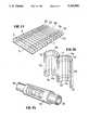
- FIG. 1is a perspective view of a V-groove machine as shown in U.S. Ser. No. 364,452, now U.S. Pat. No. 4,954,202 further including means for fixing a wire to the backing layer of the individual insulation sections;
- FIG. 2is a perspective view of one section of a composite insulating material, viewed from the surface opposite of the backing layer, including the attachment wires;
- FIG. 3is a perspective view showing the insulation section of FIG. 2 in a wrapped configuration
- FIG. 4is an exploded view of a composite insulation section comprising a backing layer, a first insulating layer, a second insulating layer, and all three of the layers together as a composite;
- FIG. 5illustrates the insulation section of FIG. 4 having V-grooves contained therein, but spaced so as to provide an oblong structure when wrapped;
- FIG. 6illustrates the section of FIG. 5 in the closed or wrapped configuration
- FIG. 7is a perspective view of the insulation section of FIG. 4 V-grooved uniformly across the length so as to provide a circular configuration when closed or wrapped;
- FIG. 8is a perspective view showing the insulation section of FIG. 7 wrapped around a pipe
- FIG. 9is an exploded view of a composite insulation section comprising a backing layer, a first insulating layer including strips of the material extending lengthwise of the section, and strips of a second insulating material positioned on each side of and between said strips;
- FIG. 10is a perspective view, partly in section, showing the insulation section of FIG. 9 V-grooved and wrapped on a pipe;
- FIG. 11is an exploded view of still another embodiment of the invention wherein the backing layer has a plurality of longitudinal sections of a first insulating material and strips of a second insulating material affixed thereto;
- FIG. 12is a perspective view of the insulation section of FIG. 11 V-grooved
- FIG. 13is a perspective view of the insulation section of FIG. 11 wherein the V-grooves are spaced to fit around a circular pipe and having one face of each of the grooves coated with an adhesive but for the middle groove;
- FIG. 14is a perspective view illustrating the insulation section of FIG. 13 with the insulation wrapped or closed so as to provide two half circles hinged through the flexible backing layer at the mid-point where the V-groove is not coated with adhesive;
- FIG. 15illustrates the insulation section of FIG. 14, partly in section, wrapped around a pipe.
- the V-grooving apparatus 10is comprised of a combination of stations each disposed along, above, or approximate to an endless track conveyor system.
- the conveyor systemas defined in Ser. No. 364,452, now U.S. Pat. No. 4,954,202 incorporated herein by reference, comprises an upright tubular frame 12 along the top of which are secured a plurality of rollers 14, or the like, to form a bed 16.
- Flexibly disposed over these rollers 14is a conventional looped belt arrangement, not shown, driven by a motor through guide rollers 18 such that the material placed atop the system will be moved longitudinally down the frame 12 for processing as shown by direction arrow A.
- the travel rate of the conveyor system and the different functionsare controlled by a microprocessor 15 which also governs the placement and frequency with which the V-grooves are cut in a given insulation section 20, or at which severance of the insulation section 20 occurs.
- insulation materialsare positioned on the conveyor in layers or in longitudinal sections, depending upon the ultimate insulation configurations desired. At times it may be desirable to adhere the layers or sections together by applying an adhesive. However, this is not normally necessary since the layer or sections are held together by the backing to be applied or the shape of the V-grooves.
- the insulating materialis sprayed with an adhesive at station 17, with a backing 22 being applied at station 19.
- the backed materialis passed through a saw station 11, at which point V-grooves are positioned in the lower surface of the composite insulation material 20 as fully described in application Ser. No. 364,456 now U.S. Pat. No. 4,954,202. Thereafter, attaching wires 24 are applied to the backing material 22.
- the microprocessor 15is programmed to provide a space between each of insulation sections 20, for example using a stepping motor.
- a plurality of wires 24are uniformly spaced on the outer surface of the backing member, with the timing being controlled so that there is a length, approximately an inch and one-half (11/2"), of wire extending beyond the leading edge of the insulation section 20, and the wire is cut after the trailing edge of the section is sensed and an additional length of approximately an inch and one-half (11/2") extends beyond the section.
- a tape 28is applied over the wire in order to firmly affix the wire to the insulation section.
- the insulation section 20 comprising the wireis shown in FIG. 2 and is shown in the wrapped position in FIG. 3.
- FIG. 4illustrates a first embodiment of the invention.
- composite insulation 40comprises a backing layer 42, a first rigid insulating material 44, and a second rigid insulating material 46.
- This total composite 40after being V-grooved, can be used to wrap various shaped objects, depending upon the spacing and frequency of the V-grooves. As shown in FIG. 5, there is a first length of close V-grooving 41, followed by a length 43 where there are no V-grooves, followed by a length of close V-grooving 41, followed by an additional length 43 where there is no V-grooving. When the V-grooved section is wrapped or closed, the insulation will have an oblong shape as shown in FIG.
- the composite insulationcan be used to wrap a round pipe 81 as illustrated in FIG. 8.
- FIG. 9is an additional embodiment of the invention comprising a backing member 90 and a first rigid composite material 92 shaped to have raised sections 91. Positioned around these raised sections is a second dissimilar insulation material 94. This material when V-grooved for circular orientation and wrapped around a circular pipe 81 has a cross-section as shown in FIG. 10.
- the composite materialcomprises a backing member 111 and, affixed to the backing member, a first insulating material 112 extending in the longitudinal or machine direction; a longitudinally or machine direction positioned dissimilar insulating material 114, followed by a second section of the first insulating material 112; then a second strip of longitudinally extending dissimilar insulating material 114 and an additional section of material 112.
- Thisprovides, therefore, a composite insulation having a flexible backing member and a first insulating material with strips of a second insulating material extending longitudinally through the section. This material when V-grooved will have the configuration of FIG. 12.
- FIG. 13illustrates an embodiment of the invention wherein after the material is V-grooved an adhesive S, such as a pressure-sensitive adhesive, is applied to one face of the V.
- an adhesive Ssuch as a pressure-sensitive adhesive
- the adhesiveis applied to one face of each of the grooves, when the material is closed at the time of installation the V-grooves will automatically adhere together in the closed configuration, providing ease of application and use of the insulation.
- one V-groove C in the center of the sectiondoes not contain an adhesive, the backing layer at that V-groove will provide a hinge H.
- the center sectionwill form a hinge for the two formed half-sections, permitting simplified installation on a pipe 81, or the like, as shown in FIG. 15.
- the composite insulating materials of the present inventioncan be tailored through use of insulating materials having diverse properties to provide composite sections of insulation ranging in width of from about four feet down to a few inches.
- Particularly preferred embodimentscomprise layered composites, wherein "layered" means a stacking of the diverse materials one on top of the other, composed of pairs of rigid materials as follows: mineral wool-foam glass; mineral wool-polyurethane foam; mineral wool-ceramic fibers; or pairs of rigid material and flexible material as follows: mineral wool-ceramic fiber blanket; mineral wool-flexible polyurethane foam. It is also possible to use three or more insulating materials.
- the mineral wool componentcan vary in thickness from about one-half inch to about four inches in thickness, with the second component varying from about one-half inch to about four inches in thickness to provide a total insulation thickness of from about one inch to five inches.
- the combinations of materialsprovide composite insulation having the advantages of one material--such as good insulative value, while minimizing disadvantages of the material--such as the difficulty of working with a material such as foam glass due to its brittleness and its relative non-conformability to diverse shapes. Additionally, the composite insulation provides economy through the use of a relatively costly material such as ceramic fiber where needed and the use of a relatively inexpensive material such as mineral wool where the properties of ceramic fiber are not necessary. For example, it is recognized that the insulation material closest to a pipe being insulated is subject to the greatest heat, and as the distance away from the pipe increases the material is subject to less heat, permitting the use of a material having a lower thermal value such as mineral wool.
- sections of material such as mineral woolare separated longitudinally or in the machine-direction with strips of a diverse material such as perlite.
- a diverse materialsuch as perlite.
- Such compositesprovide the advantages of mineral wool including relative low cost, but which suffer from low structural strength, with the high structural strength provided by perlite. This permits a strengthened insulative structure which resists high load bearings, including the weight of a pipe, and/or permits the structure to be stepped on particularly at diverse locations.
- the insulative sectioncan comprise one-half of one rigid material and one-half of another rigid material.
- the insulative sectioncan be positioned on a pipe to have the one material such as perlite positioned at the top so that the entire structure can be stepped on without damage to the insulation.
- various modificationscan be made to the composite insulation sections to utilize materials varying in cost and property characteristics. Proper selection of materials permits use of the insulation to cover pipes, commercial grease ducts, commercial and industrial cable trays, structural steel supports such as I-beams and the like, large chemical tanks, and virtually any structure where structural integrity is essential.
Landscapes
- Engineering & Computer Science (AREA)
- Mechanical Engineering (AREA)
- Architecture (AREA)
- General Engineering & Computer Science (AREA)
- Civil Engineering (AREA)
- Structural Engineering (AREA)
- Thermal Insulation (AREA)
- Laminated Bodies (AREA)
Abstract
Description
Claims (16)
Priority Applications (1)
| Application Number | Priority Date | Filing Date | Title |
|---|---|---|---|
| US07/884,871US5310594A (en) | 1990-02-05 | 1992-05-18 | Composite rigid insulation materials containing V-grooves |
Applications Claiming Priority (2)
| Application Number | Priority Date | Filing Date | Title |
|---|---|---|---|
| US47493890A | 1990-02-05 | 1990-02-05 | |
| US07/884,871US5310594A (en) | 1990-02-05 | 1992-05-18 | Composite rigid insulation materials containing V-grooves |
Related Parent Applications (1)
| Application Number | Title | Priority Date | Filing Date |
|---|---|---|---|
| US47493890AContinuation | 1990-02-05 | 1990-02-05 |
Publications (1)
| Publication Number | Publication Date |
|---|---|
| US5310594Atrue US5310594A (en) | 1994-05-10 |
Family
ID=23885582
Family Applications (1)
| Application Number | Title | Priority Date | Filing Date |
|---|---|---|---|
| US07/884,871Expired - Fee RelatedUS5310594A (en) | 1990-02-05 | 1992-05-18 | Composite rigid insulation materials containing V-grooves |
Country Status (7)
| Country | Link |
|---|---|
| US (1) | US5310594A (en) |
| AU (1) | AU660920B2 (en) |
| CA (1) | CA2035602C (en) |
| DE (1) | DE4103426A1 (en) |
| FR (1) | FR2657944B1 (en) |
| GB (1) | GB2242646B (en) |
| NZ (1) | NZ237030A (en) |
Cited By (73)
| Publication number | Priority date | Publication date | Assignee | Title |
|---|---|---|---|---|
| US5549942A (en)* | 1995-06-08 | 1996-08-27 | Watts; Anthony | Sealed ductboard |
| US5626982A (en)* | 1993-07-19 | 1997-05-06 | Kanegafuchi Chemical Industry Co., Ltd. | Heat insulating pad material, particularly for use in battery shield and manufacture of the same |
| US5725723A (en)* | 1996-05-20 | 1998-03-10 | Mineral Products & Technology, Inc. | Apparatus for making pipe insulation |
| EP0763690A3 (en)* | 1995-09-14 | 1998-04-01 | Johns Manville International, Inc. | Method of kerfing insulation boards and ducts and duct liners formed from said boards |
| US5753854A (en)* | 1996-07-31 | 1998-05-19 | Polytrap Co. Inc. | Fire-proof blanket for protection of electrical cable splices having embedded snap |
| US5843353A (en)* | 1995-04-13 | 1998-12-01 | Imperial Chemical Industries Plc | Non-planar evacuated insulation panels and a method for making same |
| US5918644A (en)* | 1996-05-23 | 1999-07-06 | Haack; C. William | Air duct and method of making same |
| WO1999033638A1 (en)* | 1997-12-23 | 1999-07-08 | Bayer Aktiengesellschaft | Method for producing a saucer-shaped vacuum insulating panel and use of same as insulating element |
| US5934338A (en)* | 1997-02-05 | 1999-08-10 | Isoltherm A.P. Ltd. | Heat insulating covering and method |
| WO1999047848A1 (en)* | 1998-03-20 | 1999-09-23 | Tuff-N-Nuff U.S.A., Inc. | Protective shield for elongated underground utilities |
| US5960602A (en)* | 1997-02-14 | 1999-10-05 | Transco Products, Inc. | Shielded metallic reflective insulation assembly |
| WO1999056068A1 (en)* | 1998-04-28 | 1999-11-04 | Bayer Aktiengesellschaft | Continuous method for producing a refrigerator |
| US6000437A (en)* | 1998-01-16 | 1999-12-14 | Certain Teed Corporation | Coated liner for curved ducts |
| US6016846A (en)* | 1996-02-07 | 2000-01-25 | Morgan Adhesives Company | Pipe insulation sleeve |
| WO2000066849A1 (en)* | 1999-04-29 | 2000-11-09 | Rockwool International A/S | Insulating product comprising fixation means and process for the production and mounting thereof |
| US6231927B1 (en) | 1999-06-08 | 2001-05-15 | Certainteed Corporation | Method of coating insulation boards |
| US20020146521A1 (en)* | 2001-02-20 | 2002-10-10 | Toas Murray S. | Moisture repellent air duct products |
| US20030082343A1 (en)* | 2001-11-01 | 2003-05-01 | Brucker Michel J. | Bendable polymeric foam with a reinforced slit |
| US20030159690A1 (en)* | 2002-02-27 | 2003-08-28 | Butler Barry Lynn | Solar heat transfer system (HTPL), high temperature pressurized loop |
| US6634390B2 (en)* | 2000-12-21 | 2003-10-21 | Peter R. Toth | Insulation cover |
| US20040137181A1 (en)* | 2003-01-14 | 2004-07-15 | Ruid John O. | Duct board with water repellant mat |
| US6769455B2 (en) | 2001-02-20 | 2004-08-03 | Certainteed Corporation | Moisture repellent air duct products |
| US20040151888A1 (en)* | 2002-05-08 | 2004-08-05 | Ruid John O. | Duct board having a facing with aligned fibers |
| US20050098255A1 (en)* | 2003-11-06 | 2005-05-12 | Lembo Michael J. | Insulation product having nonwoven facing and process for making same |
| US20050112966A1 (en)* | 2003-11-20 | 2005-05-26 | Toas Murray S. | Faced mineral fiber insulation board with integral glass fabric layer |
| US6910253B2 (en)* | 1995-02-14 | 2005-06-28 | Marc Lessard | Method of construction of an insulating air conduit |
| US20050139415A1 (en)* | 2003-12-30 | 2005-06-30 | Tilton Jeffrey A. | Acoustical substrate suitable for fabrication into a three dimensional product |
| US20050153092A1 (en)* | 2004-01-09 | 2005-07-14 | Lewis David L. | Fan-folded insulation laminate with reinforced hinges |
| US20050218655A1 (en)* | 2004-04-02 | 2005-10-06 | Certain Teed Corporation | Duct board with adhesive coated shiplap tab |
| US20050221061A1 (en)* | 2004-04-02 | 2005-10-06 | Toas Murray S | Method and apparatus for forming shiplap edge in air duct board using molding and machining |
| US20060019568A1 (en)* | 2004-07-26 | 2006-01-26 | Toas Murray S | Insulation board with air/rain barrier covering and water-repellent covering |
| US20060078699A1 (en)* | 2004-10-12 | 2006-04-13 | Mankell Kurt O | Insulation board with weather and puncture resistant facing and method of manufacturing the same |
| US20060083889A1 (en)* | 2004-10-19 | 2006-04-20 | Schuckers Douglass S | Laminated duct board |
| US20060251343A1 (en)* | 2005-05-09 | 2006-11-09 | True Charles W | Flexible independent multi-layer container and method for forming |
| US7201954B2 (en)* | 2000-06-16 | 2007-04-10 | E. I. Du Pont De Nemours And Company | Method for forming barrier structures on a substrate and the resulting article |
| US20070101674A1 (en)* | 2005-11-10 | 2007-05-10 | Malcolm Stinson | Method of making a post cover and a post cover made in accordance with the method |
| US7279438B1 (en) | 1999-02-02 | 2007-10-09 | Certainteed Corporation | Coated insulation board or batt |
| US20070275228A1 (en)* | 2006-04-11 | 2007-11-29 | Castor Bruce S | Tackable furniture panels having foam substrates |
| US20080280132A1 (en)* | 2007-05-11 | 2008-11-13 | Iso-Chemie Gbmh | Thick Insulation Band |
| US20090035490A1 (en)* | 2002-03-12 | 2009-02-05 | Palitha Wickramanayake | Chemically-bonded porous coatings that enhance humid fastness and fade fastness performance of ink jet images |
| US20090130389A1 (en)* | 2007-11-20 | 2009-05-21 | Industrial Insulation Group | Pre-applied protective jacketing to grooved insulation |
| US20090255213A1 (en)* | 2008-04-11 | 2009-10-15 | Innovida Holdings, Inc. | Sandwich panel with closed edge and methods of fabricating |
| US20090282777A1 (en)* | 2008-05-13 | 2009-11-19 | Innovida Factories, Ltd. | Angle joint for sandwich panels and method of fabricating same |
| US20090307995A1 (en)* | 2008-06-13 | 2009-12-17 | Innovida Factories, Ltd. | Roof construction joints made of sandwich panels |
| US20090320387A1 (en)* | 2008-06-27 | 2009-12-31 | Innovida Factories, Ltd. | Sandwich panel ground anchor and ground preparation for sandwich panel structures |
| US20100005732A1 (en)* | 2008-07-10 | 2010-01-14 | Innovida Holdings, Inc. | Building roof structure having a round corner |
| US20100050549A1 (en)* | 2008-08-29 | 2010-03-04 | Innovida Factories, Ltd. | Joint of parallel sandwich panels |
| US20100050553A1 (en)* | 2008-08-29 | 2010-03-04 | Innovida Factories, Ltd. | sandwich panel joint and method of joining sandwich panels |
| US20100089483A1 (en)* | 2006-09-29 | 2010-04-15 | Peter Dudley | Insulated ductwork products |
| US20100095613A1 (en)* | 2008-10-20 | 2010-04-22 | Arthur George Paetkau | Prefabricated Building Panels and Structures, Building, Methods and Systems Relating to Same |
| CN101733364A (en)* | 2008-11-12 | 2010-06-16 | 济南圣泉集团股份有限公司 | Flexible casting insulation board and preparation method thereof |
| US8381458B2 (en) | 2008-12-17 | 2013-02-26 | Genpak Llc | Vent baffles |
| US20130199119A1 (en)* | 2012-02-07 | 2013-08-08 | Concrete Log Systems, Inc. | Board and Batten Siding System |
| US8658264B2 (en) | 2009-06-25 | 2014-02-25 | Nomaco Inc. | Self-adjusting insulation, including insulation particularly suited for pipe or duct |
| US20140272311A1 (en)* | 2013-03-14 | 2014-09-18 | Millport Associates S.A. | Composite sandwich panels and method of forming round corners in composite sandwich panels |
| US20140261846A1 (en)* | 2013-03-15 | 2014-09-18 | Fran Lanciaux | Clad duct |
| WO2014151102A1 (en)* | 2013-03-15 | 2014-09-25 | Robert Bosch Gmbh | Kink resistant hose system with layer of spaced geometrical units and method of manufacturing |
| US8875475B2 (en) | 2013-03-14 | 2014-11-04 | Millport Associates S.A. | Multiple panel beams and methods |
| USD724125S1 (en) | 2013-03-01 | 2015-03-10 | Ray Charles Pierce | Cable drill bit |
| US9157566B2 (en) | 2012-05-11 | 2015-10-13 | Nomaco Inc. | Insulation systems employing expansion features to insulate elongated containers subject to extreme temperature fluctuations, and related components and methods |
| US20160319983A1 (en)* | 2008-05-01 | 2016-11-03 | Cabot Corporation | Manufacturing and Installation of Insulated Pipes or Elements Thereof |
| EP3051176A4 (en)* | 2013-12-17 | 2016-12-07 | Mitsubishi Heavy Ind Ltd | Vibration-damping material and method for attaching vibration-damping material |
| US9800027B1 (en) | 2011-02-04 | 2017-10-24 | Ray Charles Pierce | Method and apparatus for installing a plurality of cables |
| US9827745B2 (en) | 2013-06-13 | 2017-11-28 | Floracraft Corp. | Grooved polymeric insulation foam member and related method |
| WO2019050685A1 (en)* | 2017-09-05 | 2019-03-14 | Owens Corning Intellectual Capital, Llc | Conforming pipe insulation |
| US10365005B2 (en)* | 2017-07-12 | 2019-07-30 | Fernando Surraco | Stainless steel foil laminated plastic HVAC duct and method of making same |
| US10364176B1 (en) | 2016-10-03 | 2019-07-30 | Owens-Brockway Glass Container Inc. | Glass precursor gel and methods to treat with microwave energy |
| US10427970B1 (en) | 2016-10-03 | 2019-10-01 | Owens-Brockway Glass Container Inc. | Glass coatings and methods to deposit same |
| US10479717B1 (en) | 2016-10-03 | 2019-11-19 | Owens-Brockway Glass Container Inc. | Glass foam |
| US20190390870A1 (en)* | 2018-06-20 | 2019-12-26 | Johns Manville | Methods, materials, and equipment to form improved fit duct liner insulation for round and oval hvac duct systems |
| WO2021041819A1 (en)* | 2019-08-30 | 2021-03-04 | Owens Corning Intellectual Capital, Llc | Low viscosity sealant to prevent corrosion under insulation |
| WO2023038649A1 (en)* | 2021-09-08 | 2023-03-16 | Fran Lanciaux | Curved duct and method of manufacturing same |
| USD1035840S1 (en)* | 2020-03-25 | 2024-07-16 | 1552818 Ontario Limited | Pipe protector panel |
Families Citing this family (9)
| Publication number | Priority date | Publication date | Assignee | Title |
|---|---|---|---|---|
| DE4110124C2 (en)* | 1991-03-27 | 2002-02-21 | Missel Gmbh & Co E | Process for attaching a tubular composite to a sewage pipe with improved sound insulation |
| DE4133803A1 (en)* | 1991-10-12 | 1992-04-30 | Peter A Kaiser | Acoustic insulation of corrugated steel roof or facade - by folding strips of mineral fibre to fit in corrugations |
| FR2710003B1 (en)* | 1993-09-16 | 1995-11-24 | Isobox Technologies | Process for the production of expanded polystyrene objects and objects thus obtained. |
| DE19529359A1 (en)* | 1995-08-10 | 1997-02-13 | Isokauf Gmbh Daemmstoff Fachha | Insulating insert, esp. as seam filler for metal suspended roofs - comprises inserting strips which consist of flame resistant, sound-insulating melamine resin foam |
| FR2754537B1 (en)* | 1996-10-14 | 1999-01-08 | Elysees Balzac Financiere | FLAT CELLULOSIC PRODUCT SUITABLE AS A HOUSEHOLD CARE TOOL AND ITS PREPARATION |
| DE29905123U1 (en) | 1999-03-22 | 1999-07-22 | Franz Kaldewei GmbH & Co, 59229 Ahlen | Plate-shaped element |
| DE19941746A1 (en)* | 1999-09-02 | 2001-03-08 | Porextherm Daemmstoffe Gmbh | Insulation molded body and process for its production |
| WO2003002834A1 (en)* | 2001-06-29 | 2003-01-09 | Sentry Protection Products, Inc. | Apparatus for protecting a structural column |
| DE102021118244A1 (en) | 2021-07-14 | 2023-01-19 | Lionel Junique | Pipe protection hollow profile |
Citations (7)
| Publication number | Priority date | Publication date | Assignee | Title |
|---|---|---|---|---|
| US3092529A (en)* | 1955-07-01 | 1963-06-04 | Owens Corning Fiberglass Corp | Duct or conduit blank |
| US3212529A (en)* | 1961-12-11 | 1965-10-19 | Owens Corning Fiberglass Corp | Collapsible duct section |
| US3251382A (en)* | 1963-06-24 | 1966-05-17 | Tatsch Richard | Foldable conduit structure |
| US3615149A (en)* | 1968-09-20 | 1971-10-26 | Joseph G Malone | Heat insulating product |
| US3969868A (en)* | 1970-03-02 | 1976-07-20 | Winnebago Industries, Inc. | Insulation structure |
| FR2409855A1 (en)* | 1977-11-24 | 1979-06-22 | Chollet Jacques | Prefabricated refractory elements for lagging or sleeves - which can easily be bent to fit round objects for protection against fire |
| US5013597A (en)* | 1982-01-22 | 1991-05-07 | Sony Corporation | Multi-layered sound-insulating panel for motor vehicles, or similar |
Family Cites Families (10)
| Publication number | Priority date | Publication date | Assignee | Title |
|---|---|---|---|---|
| GB391541A (en)* | 1932-01-05 | 1933-05-04 | William Hamilton | Improvements in or relating to the lagging of pipes and the like |
| US2776231A (en)* | 1954-06-28 | 1957-01-01 | Armstrong Cork Co | Segmented insulating covering for pipes and the like |
| US2890739A (en)* | 1954-11-30 | 1959-06-16 | Armstrong Cork Co | Segmented insulation and method of installing the same |
| US3117902A (en)* | 1958-10-20 | 1964-01-14 | Fastab Insulations Inc | Insulating coverings for enclosures |
| GB1137121A (en)* | 1964-10-21 | 1968-12-18 | Lo Dense Fixings Rugby Ltd | Improvements in and in the manufacture of insulated ducting, tubing or casing |
| US3773604A (en)* | 1971-02-10 | 1973-11-20 | Balsa Ecuador Lumber Corp | Structural light-weight panel of high strength,having theral insulation properties and enclosures formed thereby |
| DE2836957A1 (en)* | 1978-08-24 | 1980-03-13 | Kabel Metallwerke Ghh | HEAT-INSULATED PIPE |
| FI66478C (en)* | 1981-07-06 | 1984-10-10 | Partek Ab | ROERSKAOLELEMENT OCH SAETT ATT FRAMSTAELLA DETSAMMA |
| DE3232277A1 (en)* | 1982-08-31 | 1984-03-01 | Bernd 4902 Bad Salzuflen Friemuth | Pipe insulating element |
| EP0290677A1 (en)* | 1987-05-14 | 1988-11-17 | Theodor Pecha | Process for the insulation of construction parts |
- 1991
- 1991-02-04FRFR9101214Apatent/FR2657944B1/ennot_activeExpired - Fee Related
- 1991-02-04AUAU70251/91Apatent/AU660920B2/ennot_activeCeased
- 1991-02-04CACA 2035602patent/CA2035602C/ennot_activeExpired - Lifetime
- 1991-02-05NZNZ23703091Apatent/NZ237030A/enunknown
- 1991-02-05DEDE19914103426patent/DE4103426A1/ennot_activeWithdrawn
- 1991-02-05GBGB9102442Apatent/GB2242646B/ennot_activeExpired - Fee Related
- 1992
- 1992-05-18USUS07/884,871patent/US5310594A/ennot_activeExpired - Fee Related
Patent Citations (7)
| Publication number | Priority date | Publication date | Assignee | Title |
|---|---|---|---|---|
| US3092529A (en)* | 1955-07-01 | 1963-06-04 | Owens Corning Fiberglass Corp | Duct or conduit blank |
| US3212529A (en)* | 1961-12-11 | 1965-10-19 | Owens Corning Fiberglass Corp | Collapsible duct section |
| US3251382A (en)* | 1963-06-24 | 1966-05-17 | Tatsch Richard | Foldable conduit structure |
| US3615149A (en)* | 1968-09-20 | 1971-10-26 | Joseph G Malone | Heat insulating product |
| US3969868A (en)* | 1970-03-02 | 1976-07-20 | Winnebago Industries, Inc. | Insulation structure |
| FR2409855A1 (en)* | 1977-11-24 | 1979-06-22 | Chollet Jacques | Prefabricated refractory elements for lagging or sleeves - which can easily be bent to fit round objects for protection against fire |
| US5013597A (en)* | 1982-01-22 | 1991-05-07 | Sony Corporation | Multi-layered sound-insulating panel for motor vehicles, or similar |
Cited By (105)
| Publication number | Priority date | Publication date | Assignee | Title |
|---|---|---|---|---|
| US5626982A (en)* | 1993-07-19 | 1997-05-06 | Kanegafuchi Chemical Industry Co., Ltd. | Heat insulating pad material, particularly for use in battery shield and manufacture of the same |
| US6910253B2 (en)* | 1995-02-14 | 2005-06-28 | Marc Lessard | Method of construction of an insulating air conduit |
| US5843353A (en)* | 1995-04-13 | 1998-12-01 | Imperial Chemical Industries Plc | Non-planar evacuated insulation panels and a method for making same |
| US5549942A (en)* | 1995-06-08 | 1996-08-27 | Watts; Anthony | Sealed ductboard |
| US5953818A (en)* | 1995-09-14 | 1999-09-21 | Johns Manville International, Inc. | Method of kerfing insulation boards and duct liners and the like formed from said boards |
| US6148867A (en)* | 1995-09-14 | 2000-11-21 | Johns Manville International, Inc. | Duct liners |
| EP0763690A3 (en)* | 1995-09-14 | 1998-04-01 | Johns Manville International, Inc. | Method of kerfing insulation boards and ducts and duct liners formed from said boards |
| US6457237B1 (en)* | 1995-09-14 | 2002-10-01 | Johns Manville International, Inc. | Method of kerfing insulation boards to form duct liners |
| US6016846A (en)* | 1996-02-07 | 2000-01-25 | Morgan Adhesives Company | Pipe insulation sleeve |
| WO1999020460A1 (en)* | 1996-05-20 | 1999-04-29 | Mineral Products And Technology, Inc. | Pipe insulation and method and apparatus for making |
| US5725723A (en)* | 1996-05-20 | 1998-03-10 | Mineral Products & Technology, Inc. | Apparatus for making pipe insulation |
| US5918644A (en)* | 1996-05-23 | 1999-07-06 | Haack; C. William | Air duct and method of making same |
| US5753854A (en)* | 1996-07-31 | 1998-05-19 | Polytrap Co. Inc. | Fire-proof blanket for protection of electrical cable splices having embedded snap |
| US5934338A (en)* | 1997-02-05 | 1999-08-10 | Isoltherm A.P. Ltd. | Heat insulating covering and method |
| US5960602A (en)* | 1997-02-14 | 1999-10-05 | Transco Products, Inc. | Shielded metallic reflective insulation assembly |
| WO1999033638A1 (en)* | 1997-12-23 | 1999-07-08 | Bayer Aktiengesellschaft | Method for producing a saucer-shaped vacuum insulating panel and use of same as insulating element |
| US6000437A (en)* | 1998-01-16 | 1999-12-14 | Certain Teed Corporation | Coated liner for curved ducts |
| WO1999047848A1 (en)* | 1998-03-20 | 1999-09-23 | Tuff-N-Nuff U.S.A., Inc. | Protective shield for elongated underground utilities |
| US5988227A (en)* | 1998-03-20 | 1999-11-23 | Tuff-N-Nuff Industries | Protective shield for elongated underground utilities |
| WO1999056068A1 (en)* | 1998-04-28 | 1999-11-04 | Bayer Aktiengesellschaft | Continuous method for producing a refrigerator |
| US7279438B1 (en) | 1999-02-02 | 2007-10-09 | Certainteed Corporation | Coated insulation board or batt |
| WO2000066849A1 (en)* | 1999-04-29 | 2000-11-09 | Rockwool International A/S | Insulating product comprising fixation means and process for the production and mounting thereof |
| RU2246595C2 (en)* | 1999-04-29 | 2005-02-20 | Роквул Интернэшнл А/С | Fastening means for heat insulation article |
| US6231927B1 (en) | 1999-06-08 | 2001-05-15 | Certainteed Corporation | Method of coating insulation boards |
| US7201954B2 (en)* | 2000-06-16 | 2007-04-10 | E. I. Du Pont De Nemours And Company | Method for forming barrier structures on a substrate and the resulting article |
| US6634390B2 (en)* | 2000-12-21 | 2003-10-21 | Peter R. Toth | Insulation cover |
| US6769455B2 (en) | 2001-02-20 | 2004-08-03 | Certainteed Corporation | Moisture repellent air duct products |
| US7220470B2 (en) | 2001-02-20 | 2007-05-22 | Certainteed Corporation | Moisture repellent air duct products |
| US20020146521A1 (en)* | 2001-02-20 | 2002-10-10 | Toas Murray S. | Moisture repellent air duct products |
| US20030082343A1 (en)* | 2001-11-01 | 2003-05-01 | Brucker Michel J. | Bendable polymeric foam with a reinforced slit |
| US7913684B2 (en)* | 2002-02-27 | 2011-03-29 | Barry Lynn Butler | Solar heat transfer system (HTPL), high temperature pressurized loop |
| US20030159690A1 (en)* | 2002-02-27 | 2003-08-28 | Butler Barry Lynn | Solar heat transfer system (HTPL), high temperature pressurized loop |
| US20090035490A1 (en)* | 2002-03-12 | 2009-02-05 | Palitha Wickramanayake | Chemically-bonded porous coatings that enhance humid fastness and fade fastness performance of ink jet images |
| US20040151888A1 (en)* | 2002-05-08 | 2004-08-05 | Ruid John O. | Duct board having a facing with aligned fibers |
| US7223455B2 (en) | 2003-01-14 | 2007-05-29 | Certainteed Corporation | Duct board with water repellant mat |
| US20040137181A1 (en)* | 2003-01-14 | 2004-07-15 | Ruid John O. | Duct board with water repellant mat |
| US20050031819A1 (en)* | 2003-01-14 | 2005-02-10 | Mankell Kurt O. | Duct board with low weight water repellant mat |
| US20050098255A1 (en)* | 2003-11-06 | 2005-05-12 | Lembo Michael J. | Insulation product having nonwoven facing and process for making same |
| US6986367B2 (en) | 2003-11-20 | 2006-01-17 | Certainteed Corporation | Faced mineral fiber insulation board with integral glass fabric layer |
| US20050112966A1 (en)* | 2003-11-20 | 2005-05-26 | Toas Murray S. | Faced mineral fiber insulation board with integral glass fabric layer |
| US7329456B2 (en) | 2003-12-30 | 2008-02-12 | Owens Corning Intellectual Capital, Llc | Method of fabrication of an acoustical substrate into a three dimensional product |
| US20050139415A1 (en)* | 2003-12-30 | 2005-06-30 | Tilton Jeffrey A. | Acoustical substrate suitable for fabrication into a three dimensional product |
| US6979484B2 (en) | 2004-01-09 | 2005-12-27 | Lewis David L | Fan-folded insulation laminate with reinforced hinges |
| US20050153092A1 (en)* | 2004-01-09 | 2005-07-14 | Lewis David L. | Fan-folded insulation laminate with reinforced hinges |
| US20050218655A1 (en)* | 2004-04-02 | 2005-10-06 | Certain Teed Corporation | Duct board with adhesive coated shiplap tab |
| US20050221061A1 (en)* | 2004-04-02 | 2005-10-06 | Toas Murray S | Method and apparatus for forming shiplap edge in air duct board using molding and machining |
| US20060019568A1 (en)* | 2004-07-26 | 2006-01-26 | Toas Murray S | Insulation board with air/rain barrier covering and water-repellent covering |
| US8215083B2 (en) | 2004-07-26 | 2012-07-10 | Certainteed Corporation | Insulation board with air/rain barrier covering and water-repellent covering |
| US20090266025A1 (en)* | 2004-07-26 | 2009-10-29 | Certainteed Corporation | Insulation board with air/rain barrier covering and water-repellent covering |
| US20060078699A1 (en)* | 2004-10-12 | 2006-04-13 | Mankell Kurt O | Insulation board with weather and puncture resistant facing and method of manufacturing the same |
| US20060083889A1 (en)* | 2004-10-19 | 2006-04-20 | Schuckers Douglass S | Laminated duct board |
| US20060251343A1 (en)* | 2005-05-09 | 2006-11-09 | True Charles W | Flexible independent multi-layer container and method for forming |
| US20070101674A1 (en)* | 2005-11-10 | 2007-05-10 | Malcolm Stinson | Method of making a post cover and a post cover made in accordance with the method |
| US20070275228A1 (en)* | 2006-04-11 | 2007-11-29 | Castor Bruce S | Tackable furniture panels having foam substrates |
| US20100089483A1 (en)* | 2006-09-29 | 2010-04-15 | Peter Dudley | Insulated ductwork products |
| US8950439B2 (en)* | 2006-09-29 | 2015-02-10 | Spiralite Holdings Limited | Insulated ductwork products |
| US20080280132A1 (en)* | 2007-05-11 | 2008-11-13 | Iso-Chemie Gbmh | Thick Insulation Band |
| US20090130389A1 (en)* | 2007-11-20 | 2009-05-21 | Industrial Insulation Group | Pre-applied protective jacketing to grooved insulation |
| EP2223002A4 (en)* | 2007-11-20 | 2016-11-09 | Ind Insulation Group Llc | PROTECTIVE SLEEVING PRE-APPLIED TO GROOVED INSULATION |
| WO2009067318A3 (en)* | 2007-11-20 | 2009-08-06 | Ind Insulation Group | Pre-applied protective jacketing to grooved insulation |
| US9044895B2 (en)* | 2007-11-20 | 2015-06-02 | Thomas Whitaker | Pre-applied protective jacketing to grooved insulation |
| WO2009067318A2 (en) | 2007-11-20 | 2009-05-28 | Industrial Insulation Group | Pre-applied protective jacketing to grooved insulation |
| US20120160401A1 (en)* | 2007-11-20 | 2012-06-28 | Industrial Insulation Group | Pre-applied protective jacketing to grooved insulation |
| US8142879B2 (en) | 2007-11-20 | 2012-03-27 | Industrial Insulation Group | Pre-applied protective jacketing to grooved insulation |
| US20090255213A1 (en)* | 2008-04-11 | 2009-10-15 | Innovida Holdings, Inc. | Sandwich panel with closed edge and methods of fabricating |
| US10132441B2 (en)* | 2008-05-01 | 2018-11-20 | Cabot Corporation | Manufacturing and installation of insulated pipes or elements thereof |
| US20160319983A1 (en)* | 2008-05-01 | 2016-11-03 | Cabot Corporation | Manufacturing and Installation of Insulated Pipes or Elements Thereof |
| US20090282777A1 (en)* | 2008-05-13 | 2009-11-19 | Innovida Factories, Ltd. | Angle joint for sandwich panels and method of fabricating same |
| US20090307995A1 (en)* | 2008-06-13 | 2009-12-17 | Innovida Factories, Ltd. | Roof construction joints made of sandwich panels |
| US8733033B2 (en) | 2008-06-27 | 2014-05-27 | Millport Associates, SA | Sandwich panel ground anchor and ground preparation for sandwich panel structures |
| US20090320387A1 (en)* | 2008-06-27 | 2009-12-31 | Innovida Factories, Ltd. | Sandwich panel ground anchor and ground preparation for sandwich panel structures |
| US8782991B2 (en) | 2008-07-10 | 2014-07-22 | Millport Associates S.A. | Building roof structure having a round corner |
| US20100005732A1 (en)* | 2008-07-10 | 2010-01-14 | Innovida Holdings, Inc. | Building roof structure having a round corner |
| US20100050549A1 (en)* | 2008-08-29 | 2010-03-04 | Innovida Factories, Ltd. | Joint of parallel sandwich panels |
| US20100050553A1 (en)* | 2008-08-29 | 2010-03-04 | Innovida Factories, Ltd. | sandwich panel joint and method of joining sandwich panels |
| US20100095613A1 (en)* | 2008-10-20 | 2010-04-22 | Arthur George Paetkau | Prefabricated Building Panels and Structures, Building, Methods and Systems Relating to Same |
| US8033065B2 (en)* | 2008-10-20 | 2011-10-11 | Arthur George Paetkau | Prefabricated building panels and structures, building, methods and systems relating to same |
| CN101733364B (en)* | 2008-11-12 | 2013-04-03 | 济南圣泉集团股份有限公司 | Flexible casting insulation board and preparation method thereof |
| CN101733364A (en)* | 2008-11-12 | 2010-06-16 | 济南圣泉集团股份有限公司 | Flexible casting insulation board and preparation method thereof |
| US8381458B2 (en) | 2008-12-17 | 2013-02-26 | Genpak Llc | Vent baffles |
| US8658264B2 (en) | 2009-06-25 | 2014-02-25 | Nomaco Inc. | Self-adjusting insulation, including insulation particularly suited for pipe or duct |
| US9800027B1 (en) | 2011-02-04 | 2017-10-24 | Ray Charles Pierce | Method and apparatus for installing a plurality of cables |
| US20130199119A1 (en)* | 2012-02-07 | 2013-08-08 | Concrete Log Systems, Inc. | Board and Batten Siding System |
| US9157566B2 (en) | 2012-05-11 | 2015-10-13 | Nomaco Inc. | Insulation systems employing expansion features to insulate elongated containers subject to extreme temperature fluctuations, and related components and methods |
| USD724125S1 (en) | 2013-03-01 | 2015-03-10 | Ray Charles Pierce | Cable drill bit |
| US8875475B2 (en) | 2013-03-14 | 2014-11-04 | Millport Associates S.A. | Multiple panel beams and methods |
| US20140272311A1 (en)* | 2013-03-14 | 2014-09-18 | Millport Associates S.A. | Composite sandwich panels and method of forming round corners in composite sandwich panels |
| CN105393034A (en)* | 2013-03-15 | 2016-03-09 | 菲斯卡公司 | Kink resistant hose system with layer of spaced geometrical units and method of manufacturing |
| WO2014151102A1 (en)* | 2013-03-15 | 2014-09-25 | Robert Bosch Gmbh | Kink resistant hose system with layer of spaced geometrical units and method of manufacturing |
| US9644780B2 (en) | 2013-03-15 | 2017-05-09 | Fiskars Oyj Abp | Kink resistant hose system with layer of spaced geometrical units and method of manufacturing |
| US20140261846A1 (en)* | 2013-03-15 | 2014-09-18 | Fran Lanciaux | Clad duct |
| US9840050B2 (en)* | 2013-03-15 | 2017-12-12 | Fran Lanciaux | Clad duct |
| US9827745B2 (en) | 2013-06-13 | 2017-11-28 | Floracraft Corp. | Grooved polymeric insulation foam member and related method |
| EP3051176A4 (en)* | 2013-12-17 | 2016-12-07 | Mitsubishi Heavy Ind Ltd | Vibration-damping material and method for attaching vibration-damping material |
| US10479717B1 (en) | 2016-10-03 | 2019-11-19 | Owens-Brockway Glass Container Inc. | Glass foam |
| US10364176B1 (en) | 2016-10-03 | 2019-07-30 | Owens-Brockway Glass Container Inc. | Glass precursor gel and methods to treat with microwave energy |
| US10427970B1 (en) | 2016-10-03 | 2019-10-01 | Owens-Brockway Glass Container Inc. | Glass coatings and methods to deposit same |
| US10365005B2 (en)* | 2017-07-12 | 2019-07-30 | Fernando Surraco | Stainless steel foil laminated plastic HVAC duct and method of making same |
| WO2019050685A1 (en)* | 2017-09-05 | 2019-03-14 | Owens Corning Intellectual Capital, Llc | Conforming pipe insulation |
| US20190390870A1 (en)* | 2018-06-20 | 2019-12-26 | Johns Manville | Methods, materials, and equipment to form improved fit duct liner insulation for round and oval hvac duct systems |
| US10782046B2 (en)* | 2018-06-20 | 2020-09-22 | Johns Manville | Methods, materials, and equipment to form improved fit duct liner insulation for round and oval HVAC duct systems |
| WO2021041819A1 (en)* | 2019-08-30 | 2021-03-04 | Owens Corning Intellectual Capital, Llc | Low viscosity sealant to prevent corrosion under insulation |
| CN114502863A (en)* | 2019-08-30 | 2022-05-13 | 欧文斯科宁知识产权资产有限公司 | Low viscosity sealant for preventing corrosion under insulation |
| USD1035840S1 (en)* | 2020-03-25 | 2024-07-16 | 1552818 Ontario Limited | Pipe protector panel |
| WO2023038649A1 (en)* | 2021-09-08 | 2023-03-16 | Fran Lanciaux | Curved duct and method of manufacturing same |
Also Published As
| Publication number | Publication date |
|---|---|
| GB2242646A (en) | 1991-10-09 |
| GB2242646B (en) | 1994-08-24 |
| FR2657944A1 (en) | 1991-08-09 |
| AU7025191A (en) | 1991-08-08 |
| CA2035602A1 (en) | 1991-08-06 |
| AU660920B2 (en) | 1995-07-13 |
| GB9102442D0 (en) | 1991-03-20 |
| CA2035602C (en) | 2001-01-02 |
| NZ237030A (en) | 1993-11-25 |
| DE4103426A1 (en) | 1991-08-08 |
| FR2657944B1 (en) | 1992-09-04 |
Similar Documents
| Publication | Publication Date | Title |
|---|---|---|
| US5310594A (en) | Composite rigid insulation materials containing V-grooves | |
| US9044895B2 (en) | Pre-applied protective jacketing to grooved insulation | |
| US5733624A (en) | Mineral fiber insulation batt impregnated with coextruded polymer layering system | |
| US3733232A (en) | Method for making building sheathing elements | |
| EP1265744B1 (en) | Fiber reinforced composite cores | |
| US4128678A (en) | Heat insulating material and method of and apparatus for the manufacture thereof | |
| EP0835750A3 (en) | Polyisocyanurate foam boards with reduced moisture absorbency and lower air permeability and related methods | |
| CA2216027A1 (en) | Composite roofing members having improved dimensional stability and related methods | |
| PL184690B1 (en) | Jacketed insulating unit | |
| EP0828965B1 (en) | A method of insulating a pipe with a tubular sheathing | |
| US5899044A (en) | Post enclosure | |
| DE10142719A1 (en) | Heat insulated pipe | |
| GB2227712A (en) | Manufacturing an insulating panel | |
| US2946371A (en) | Method of making thermal pipe insulation | |
| US5934338A (en) | Heat insulating covering and method | |
| EP0004086A2 (en) | Lamellated insulating plate material, and method for manufacturing it | |
| US20030234058A1 (en) | Reinforced, self-closing pipe insulation device | |
| US4140825A (en) | Artificial thatched roof of overlapping plastic tubes, and method and apparatus for making same | |
| CZ248794A3 (en) | Building panel | |
| NZ283299A (en) | Continuous mouldings; apparatus and method for production, continuous material web adhesively laminated about profiled core member, laminating roller details | |
| US4673614A (en) | Roof insulation board and method of making | |
| US4231825A (en) | Method of making jacketed foam pipe insulation | |
| JPH05203097A (en) | Heat insulating material of pipe bend and its coating | |
| EP1208962B1 (en) | Method for the continuous production of an insulating pipe comprising at least three layers | |
| CA2222013C (en) | A method of insulating a pipe with a tubular sheathing |
Legal Events
| Date | Code | Title | Description |
|---|---|---|---|
| FEPP | Fee payment procedure | Free format text:PAYOR NUMBER ASSIGNED (ORIGINAL EVENT CODE: ASPN); ENTITY STATUS OF PATENT OWNER: SMALL ENTITY | |
| AS | Assignment | Owner name:ROCK WOOL MANUFACTURING CO., ALABAMA Free format text:ASSIGNMENT OF ASSIGNORS INTEREST.;ASSIGNORS:INDUSTRIAL INSULATIONS OF TEXAS, INC.;FIRST MISSISSIPPI CORPORATION;REEL/FRAME:006481/0345 Effective date:19930322 Owner name:MINERAL PRODUCTS AND TECHNOLOGY, INC., ALABAMA Free format text:ASSIGNMENT OF ASSIGNORS INTEREST.;ASSIGNORS:INDUSTRIAL INSULATIONS OF TEXAS, INC.;FIRST MISSISSIPPI CORPORATION;REEL/FRAME:006481/0345 Effective date:19930322 | |
| AS | Assignment | Owner name:MINERAL PRODUCTS AND TECHNOLOGY, INC., ALABAMA Free format text:ASSIGNMENT OF ASSIGNORS INTEREST;ASSIGNOR:ROCK WOOL MANUFACTURING COMPANY;REEL/FRAME:006744/0573 Effective date:19930820 | |
| FPAY | Fee payment | Year of fee payment:4 | |
| SULP | Surcharge for late payment | ||
| REMI | Maintenance fee reminder mailed | ||
| FPAY | Fee payment | Year of fee payment:8 | |
| SULP | Surcharge for late payment | Year of fee payment:7 | |
| REMI | Maintenance fee reminder mailed | ||
| LAPS | Lapse for failure to pay maintenance fees | ||
| STCH | Information on status: patent discontinuation | Free format text:PATENT EXPIRED DUE TO NONPAYMENT OF MAINTENANCE FEES UNDER 37 CFR 1.362 | |
| FP | Lapsed due to failure to pay maintenance fee | Effective date:20060510 |