US5310029A - Brake tube coupling - Google Patents
Brake tube couplingDownload PDFInfo
- Publication number
- US5310029A US5310029AUS07/962,780US96278092AUS5310029AUS 5310029 AUS5310029 AUS 5310029AUS 96278092 AUS96278092 AUS 96278092AUS 5310029 AUS5310029 AUS 5310029A
- Authority
- US
- United States
- Prior art keywords
- tube
- fitting
- flange
- fittings
- coupling
- Prior art date
- Legal status (The legal status is an assumption and is not a legal conclusion. Google has not performed a legal analysis and makes no representation as to the accuracy of the status listed.)
- Expired - Lifetime
Links
- 230000008878couplingEffects0.000titleclaimsdescription34
- 238000010168coupling processMethods0.000titleclaimsdescription34
- 238000005859coupling reactionMethods0.000titleclaimsdescription34
- 239000012530fluidSubstances0.000claimsdescription19
- 239000004033plasticSubstances0.000claimsdescription8
- 229920003023plasticPolymers0.000claimsdescription8
- 239000000463materialSubstances0.000claimsdescription7
- 230000000295complement effectEffects0.000claimsdescription6
- 230000013011matingEffects0.000claimsdescription4
- 239000002184metalSubstances0.000claimsdescription4
- 239000012858resilient materialSubstances0.000claims3
- 239000004677NylonSubstances0.000claims1
- 229920001778nylonPolymers0.000claims1
- 238000007789sealingMethods0.000abstractdescription9
- 230000007797corrosionEffects0.000abstractdescription6
- 238000005260corrosionMethods0.000abstractdescription6
- 229910000831SteelInorganic materials0.000description2
- 238000010276constructionMethods0.000description2
- 239000010959steelSubstances0.000description2
- 229920003189Nylon 4,6Polymers0.000description1
- 230000009172burstingEffects0.000description1
- 230000006835compressionEffects0.000description1
- 238000007906compressionMethods0.000description1
- 238000009434installationMethods0.000description1
- 238000004519manufacturing processMethods0.000description1
Images
Classifications
- F—MECHANICAL ENGINEERING; LIGHTING; HEATING; WEAPONS; BLASTING
- F16—ENGINEERING ELEMENTS AND UNITS; GENERAL MEASURES FOR PRODUCING AND MAINTAINING EFFECTIVE FUNCTIONING OF MACHINES OR INSTALLATIONS; THERMAL INSULATION IN GENERAL
- F16L—PIPES; JOINTS OR FITTINGS FOR PIPES; SUPPORTS FOR PIPES, CABLES OR PROTECTIVE TUBING; MEANS FOR THERMAL INSULATION IN GENERAL
- F16L25/00—Construction or details of pipe joints not provided for in, or of interest apart from, groups F16L13/00 - F16L23/00
Definitions
- This inventionrelates to brake tubes and more particularly to brake tube couplings for releasably connecting brake tubes to components of a vehicle hydraulic brake system.
- Couplings with complementarily threaded male and female fittingsare commonly used to connect brake tubes to components of a vehicle brake system.
- the threaded male fittinghas a through passage receiving a brake tube which is flared at its end and traps the male fitting on the brake tube.
- the threaded female fittinghas a through passage extending to a raised conic end section. As the male and female fittings are threaded together, the flared end of the brake tube is forced into sealing engagement with the conic section.
- both connectorsmust be constructed of metal, and 20-25 ft./lbs. of torque are required to threadingly engage the fittings to form an adequate face seal between the conic section of the female and the flared end of the brake tube.
- a high quality surface finishis also required on both the conic section of the female fitting and the corresponding complementary conical portion of the flared end of the brake tube.
- the sealcan be unreliable because of an inability to maintain close tolerances and a high quality surface finish on mass produced parts. In use, corrosion between the two metal fitting bodies and the metal brake tube complicates servicing and replacement of brake component parts and may cause seal failures.
- the extent of compression of the O-ringis accurately controlled by engagement of the flange with the tapered conical cavity within the female fitting.
- the cavitycommunicates with brake fluid to force the O-ring into sealing engagement when the brake fluid is pressurized by application of the brakes.
- a satisfactory sealcan be achieved with only 2 or 3 pounds of torque applied to secure together the threaded fittings.
- at least the male fittingis made of plastic which eliminates corrosion between the coupling components.
- Objects, features and advantages of this inventionare to provide a high pressure fluid coupling which provides a suitable seal with low connecting torque, eliminates corrosion, does not require a critical finish of sealing surfaces, is highly reliable, rugged, durable, of relatively simple design and economical manufacture and assembly, and has a long in service useful life.
- FIG. 1is a perspective view of a hydraulic brake master cylinder and fluid reservoir and four brake tubes, each being connected with a coupling of this invention, the entire assembly being mounted to a sidewall beneath a hood of a vehicle;
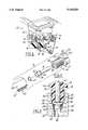
- FIG. 2is an exploded view of the coupling of this invention illustrating its male and female fittings, O-ring and brake tube end;
- FIG. 3is a sectional view taken generally on line 33 of FIG. 1 and illustrating the fittings and brake tube of the coupling in assembled and sealing relationship.
- FIG. 1illustrates a hydraulic brake master cylinder and reservoir 10 with a housing 12 to which brake tubes 14 are connected by couplings 16 embodying this invention.
- each couplinghas complementarily threaded male and female fittings 18 & 20 between which a flared end 22 of the tube with an O-ring 24 thereon are received.
- the tubehas a circumferentially continuous flange 26 adjacent the base of an outwardly flared end or frusto-conical portion 28 over which, in assembly, the O-ring is received and bears on the flange.
- the brake tubeis made from steel and the flared end is formed by cold heading to form the flared portion and to upset the flange.
- the male fittinghas a body 29 with a head 30, a shank 32 and a central passage 34 through which the tube is slidably received.
- the shankhas an end face 36 which, in assembly, bears on the flange 26 of the tube and threads 38 engageable with complementary threads in the female fitting.
- the head 30is non-circular and preferably has a pair of spaced apart and parallel flats 40 engageable by a tool, such as a wrench.
- the female fitting 20has a body 42 with exterior flat faces 44, preferably in a hexagonal configuration, for engagement by a tool, such as a wrench, to facilitate assembly and tightening of the coupling.
- the bodyhas a central through passage 46 with a counterbore 48 at one end having complementary threads 50 for mating engagement with the threaded shank 32 of the male fitting.
- the O-ring 24 and flared end 22 of the tubeare received in a frusto-conical cavity 52 disposed in the passage 46 adjacent the counterbore.
- the sidewall 54 of the frusto-conical cavitysealingly engages the O-ring and tapers inwardly in a direction generally opposed to or reversed from the taper of the conical flared portion 28 of the tube.
- the flange 26, flared portion 28 of the tube, and conical reverse tapered cavity 52 of the fittingare constructed, arranged and dimensioned so that in assembly the O-ring is generally radially compressed or distorted from its unstressed state into firm engagement with both the tube and the female fitting to provide a seal between them.
- the flange 26 and conical cavity 52are dimensioned to provide a positive stop so that in assembly the flange seats on the sidewall 54 of the conical cavity before the threaded shank 32 of the male fastener bottoms out in the counterbore 48 of the female fitting.
- the O-ringWhen assembled, the O-ring is desirably compressed about 10% to 30%, and preferably about 12% to 15%, of its nominal cross sectional diameter in its unstressed state.
- the flared portion 28 of the brake tubeis spaced from the conical cavity of the female fitting to provide a circumferential space 56 so that the brake fluid acts on the exposed surface of the O-ring when the brakes are applied to force the O-ring into firm sealing engagement with both the brake tube and the female fitting.
- the male fittingis made of a rigid plastic material, such as Nylon 46.
- the female fitting or both the male and female fittingscan be made of a rigid plastic material. Fittings of a plastic material provide sufficient connecting or fastening strength because of the relatively small force required to compress the O-ring, seat the tube flange, and resist the generally axial load applied to the coupling by the brake fluid acting on the O-ring and tube flange. With preferably course threads of the fittings, the coupling can provide a fluid tight seal with a pressure exceeding the bursting strength of about 20,000 psi of conventional steel brake tubes or lines.
- the male fitting 18is telescoped over the tube 14 so that its end face 36 is adjacent the tube flange 26 and the O-ring 24 is received by the flared portion 28 adjacent the flange.
- the tube end 22 and shank 32are inserted into the open end of the female fitting 20 and the fittings are relatively turned or rotated to thread the shank of the male fitting into the threaded counterbore 48 of the female fitting.
- the fittingsare threaded together sufficiently to urge the end face 36 of the male fitting to bear on the tube flange 26 and urge it into engagement with the sidewall 54 of the conical cavity 52 of the female fitting.
- a torque of only 2 or 3 foot poundsis applied to the fittings to seat the flange of the tube in the conical cavity.
- the O-ring 24When assembled, the O-ring 24 is generally radially compressed and urged into sealing engagement with both the tube and the female fitting to provide a seal therebetween. When the brake fluid is pressurized by application of the brakes, it also urges the O-ring into firm sealing engagement.
- This construction and arrangementprovides a fluid tight seal which does not leak of 12,000 to 15,000 psi.
- automobile hydraulic brake systemsproduce a maximum pressure of the brake fluid of less than 2500 psi. Therefore, this construction provides a highly satisfactory coupling and seal for hydraulic brake systems for vehicle applications.
Landscapes
- Engineering & Computer Science (AREA)
- General Engineering & Computer Science (AREA)
- Mechanical Engineering (AREA)
- Valves And Accessory Devices For Braking Systems (AREA)
Abstract
Description
Claims (18)
Priority Applications (1)
| Application Number | Priority Date | Filing Date | Title |
|---|---|---|---|
| US07/962,780US5310029A (en) | 1992-10-19 | 1992-10-19 | Brake tube coupling |
Applications Claiming Priority (1)
| Application Number | Priority Date | Filing Date | Title |
|---|---|---|---|
| US07/962,780US5310029A (en) | 1992-10-19 | 1992-10-19 | Brake tube coupling |
Publications (1)
| Publication Number | Publication Date |
|---|---|
| US5310029Atrue US5310029A (en) | 1994-05-10 |
Family
ID=25506348
Family Applications (1)
| Application Number | Title | Priority Date | Filing Date |
|---|---|---|---|
| US07/962,780Expired - LifetimeUS5310029A (en) | 1992-10-19 | 1992-10-19 | Brake tube coupling |
Country Status (1)
| Country | Link |
|---|---|
| US (1) | US5310029A (en) |
Cited By (5)
| Publication number | Priority date | Publication date | Assignee | Title |
|---|---|---|---|---|
| US20050057089A1 (en)* | 2003-09-16 | 2005-03-17 | Masuhiro Kondo | Brake units |
| US20050099006A1 (en)* | 2003-11-07 | 2005-05-12 | White Richard P. | Tapered ceramic GC fitting and assembly |
| US9217522B1 (en)* | 2008-02-08 | 2015-12-22 | John W. Best | Method of coupling narrow diameter tubing to a CPI port |
| US11543062B2 (en) | 2020-03-25 | 2023-01-03 | Cooper-Standard Automotive Inc. | Reversible brake tube connector |
| US12173814B2 (en) | 2022-03-18 | 2024-12-24 | Martinrea International US Inc. | Female ISO flare union with integrated mating brake ISO F flare port |
Citations (6)
| Publication number | Priority date | Publication date | Assignee | Title |
|---|---|---|---|---|
| US1508026A (en)* | 1919-03-15 | 1924-09-09 | Tubular Woven Fabric Company | Clutch for axial traction |
| US1687386A (en)* | 1928-10-09 | reeve | ||
| US2332682A (en)* | 1941-11-26 | 1943-10-26 | Imp Brass Mfg Co | Anchored flexible coupling |
| US2450581A (en)* | 1945-03-28 | 1948-10-05 | Flex O Tube Company | Swivel connection |
| US3915479A (en)* | 1974-11-29 | 1975-10-28 | Thomas & Betts Corp | Connector for flexible conduit |
| US4664425A (en)* | 1985-12-12 | 1987-05-12 | Murray Europe S.P.A. | Pipe-flange coupling with irreversible screwing at rotation |
- 1992
- 1992-10-19USUS07/962,780patent/US5310029A/ennot_activeExpired - Lifetime
Patent Citations (6)
| Publication number | Priority date | Publication date | Assignee | Title |
|---|---|---|---|---|
| US1687386A (en)* | 1928-10-09 | reeve | ||
| US1508026A (en)* | 1919-03-15 | 1924-09-09 | Tubular Woven Fabric Company | Clutch for axial traction |
| US2332682A (en)* | 1941-11-26 | 1943-10-26 | Imp Brass Mfg Co | Anchored flexible coupling |
| US2450581A (en)* | 1945-03-28 | 1948-10-05 | Flex O Tube Company | Swivel connection |
| US3915479A (en)* | 1974-11-29 | 1975-10-28 | Thomas & Betts Corp | Connector for flexible conduit |
| US4664425A (en)* | 1985-12-12 | 1987-05-12 | Murray Europe S.P.A. | Pipe-flange coupling with irreversible screwing at rotation |
Cited By (6)
| Publication number | Priority date | Publication date | Assignee | Title |
|---|---|---|---|---|
| US20050057089A1 (en)* | 2003-09-16 | 2005-03-17 | Masuhiro Kondo | Brake units |
| US20050099006A1 (en)* | 2003-11-07 | 2005-05-12 | White Richard P. | Tapered ceramic GC fitting and assembly |
| US6981720B2 (en)* | 2003-11-07 | 2006-01-03 | Agilent Technologies, Inc. | Tapered ceramic GC fitting and assembly |
| US9217522B1 (en)* | 2008-02-08 | 2015-12-22 | John W. Best | Method of coupling narrow diameter tubing to a CPI port |
| US11543062B2 (en) | 2020-03-25 | 2023-01-03 | Cooper-Standard Automotive Inc. | Reversible brake tube connector |
| US12173814B2 (en) | 2022-03-18 | 2024-12-24 | Martinrea International US Inc. | Female ISO flare union with integrated mating brake ISO F flare port |
Similar Documents
| Publication | Publication Date | Title |
|---|---|---|
| US5533764A (en) | Transverse hydraulic coupling with lipped port | |
| US7032934B2 (en) | Hydraulic fitting | |
| US5529349A (en) | Mounting apparatus with reduced resistance bead seal | |
| US6327771B1 (en) | Method of forming a flared-end pipe with a reduced resistance bead seal and method of use | |
| EP0219228B1 (en) | Quick connect tube coupling assembly | |
| CA2578446C (en) | Adaptor and method for converting standard tube fitting/port to push-to-connect tube fitting/port | |
| US8240719B2 (en) | Adaptor and method for converting standard tube fitting/port to push-to-connect tube fitting/port | |
| CA1317611C (en) | Adapter seal | |
| CA2513827C (en) | Straight thread adjustable port end | |
| CA2637939C (en) | Adaptor and method for converting standard tube fitting/port to push-to-connect tube fitting/port | |
| AU734947B2 (en) | Quick-connect coupling for articulating hose lines | |
| US6729659B2 (en) | Flare fitting assembly with metal-to-metal line seal | |
| EP0178245B1 (en) | Airspring with pneumatic fitting | |
| US5310029A (en) | Brake tube coupling | |
| EP1076198A1 (en) | Coupling | |
| US7588253B2 (en) | Sealing system with sealing ring | |
| US6702258B1 (en) | Universal ball valve assembly | |
| US4715107A (en) | Method of forming an airspring with pneumatic fitting | |
| US20030197379A1 (en) | Multi-sealing compression fitting for plumbing connections | |
| CA2294354A1 (en) | Nut and bolt securing device |
Legal Events
| Date | Code | Title | Description |
|---|---|---|---|
| AS | Assignment | Owner name:BUNDY CORPORATION, MICHIGAN Free format text:ASSIGNMENT OF ASSIGNORS INTEREST.;ASSIGNOR:KUJAWSKI, RICK A.;REEL/FRAME:006307/0445 Effective date:19920930 | |
| STCF | Information on status: patent grant | Free format text:PATENTED CASE | |
| FEPP | Fee payment procedure | Free format text:PAYOR NUMBER ASSIGNED (ORIGINAL EVENT CODE: ASPN); ENTITY STATUS OF PATENT OWNER: LARGE ENTITY | |
| FPAY | Fee payment | Year of fee payment:4 | |
| AS | Assignment | Owner name:TI GROUP AUTOMOTIVE SYSTEMS CORPORATION, MICHIGAN Free format text:CHANGE OF NAME;ASSIGNOR:BUNDY CORPORATION;REEL/FRAME:010859/0541 Effective date:19991012 | |
| FEPP | Fee payment procedure | Free format text:PAYOR NUMBER ASSIGNED (ORIGINAL EVENT CODE: ASPN); ENTITY STATUS OF PATENT OWNER: LARGE ENTITY Free format text:PAYER NUMBER DE-ASSIGNED (ORIGINAL EVENT CODE: RMPN); ENTITY STATUS OF PATENT OWNER: LARGE ENTITY | |
| FPAY | Fee payment | Year of fee payment:8 | |
| AS | Assignment | Owner name:TI GROUP AUTOMOTIVE SYSTEMS, LLC, MICHIGAN Free format text:MERGER;ASSIGNOR:TI GROUP AUTOMOTIVE SYSTEMS CORPORATION;REEL/FRAME:012407/0436 Effective date:20010625 | |
| FPAY | Fee payment | Year of fee payment:12 | |
| AS | Assignment | Owner name:JPMORGAN CHASE BANK, N.A., NEW YORK Free format text:SECURITY AGREEMENT;ASSIGNORS:HANIL USA, L.L.C.;TI AUTOMOTIVE, L.L.C.;TI GROUP AUTOMOTIVE SYSTEMS, L.L.C.;REEL/FRAME:019733/0933 Effective date:20070629 Owner name:JPMORGAN CHASE BANK, N.A.,NEW YORK Free format text:SECURITY AGREEMENT;ASSIGNORS:HANIL USA, L.L.C.;TI AUTOMOTIVE, L.L.C.;TI GROUP AUTOMOTIVE SYSTEMS, L.L.C.;REEL/FRAME:019733/0933 Effective date:20070629 | |
| AS | Assignment | Owner name:WILMINGTON TRUST (LONDON) LIMITED,UNITED KINGDOM Free format text:ASSIGNMENT OF SECURITY INTEREST;ASSIGNOR:JP MORGAN CHASE BANK, N.A.;REEL/FRAME:024055/0633 Effective date:20100208 Owner name:WILMINGTON TRUST (LONDON) LIMITED, UNITED KINGDOM Free format text:ASSIGNMENT OF SECURITY INTEREST;ASSIGNOR:JP MORGAN CHASE BANK, N.A.;REEL/FRAME:024055/0633 Effective date:20100208 | |
| AS | Assignment | Owner name:TI GROUP AUTOMOTIVE SYSTEMS, L.L.C., MICHIGAN Free format text:RELEASE AND TERMINATION OF PATENT SECURITY INTEREST;ASSIGNOR:WILMINGTON TRUST (LONDON) LIMITED (AS SUCCESSOR IN INTEREST TO JP MORGAN CHASE BANK, N.A.);REEL/FRAME:024891/0671 Effective date:20100825 Owner name:CITIBANK N.A., DELAWARE Free format text:ABL PATENT SECURITY AGREEMENT;ASSIGNOR:TI GROUP AUTOMOTIVE SYSTEMS, L.L.C.;REEL/FRAME:024895/0956 Effective date:20100825 Owner name:HANIL USA, L.L.C., MICHIGAN Free format text:RELEASE AND TERMINATION OF PATENT SECURITY INTEREST;ASSIGNOR:WILMINGTON TRUST (LONDON) LIMITED (AS SUCCESSOR IN INTEREST TO JP MORGAN CHASE BANK, N.A.);REEL/FRAME:024891/0671 Effective date:20100825 Owner name:CITIBANK N.A., DELAWARE Free format text:TERM PATENT SECURITY AGREEMENT;ASSIGNOR:TI GROUP AUTOMOTIVE SYSTEMS, L.L.C.;REEL/FRAME:024896/0057 Effective date:20100825 Owner name:TI AUTOMOTIVE, L.L.C., MICHIGAN Free format text:RELEASE AND TERMINATION OF PATENT SECURITY INTEREST;ASSIGNOR:WILMINGTON TRUST (LONDON) LIMITED (AS SUCCESSOR IN INTEREST TO JP MORGAN CHASE BANK, N.A.);REEL/FRAME:024891/0671 Effective date:20100825 | |
| AS | Assignment | Owner name:TI GROUP AUTOMOTIVE SYSTEMS, L.L.C., MICHIGAN Free format text:RELEASE BY SECURED PARTY;ASSIGNOR:CITIBANK, N.A.;REEL/FRAME:027865/0016 Effective date:20120314 Owner name:JPMORGAN CHASE BANK, N.A., NEW YORK Free format text:SECURITY AGREEMENT;ASSIGNORS:TI GROUP AUTOMOTIVE SYSTEMS, L.L.C.;TI AUTOMOTIVE LIMITED;TI AUTOMOTIVE CANADA, INC.;AND OTHERS;REEL/FRAME:027864/0968 Effective date:20120314 | |
| AS | Assignment | Owner name:TI AUTOMOTIVE CANADA, INC., CANADA Free format text:TERMINATION AND RELEASE;ASSIGNOR:JPMORGAN CHASE BANK, N.A., AS ADMINISTRATIVE AGENT;REEL/FRAME:036013/0775 Effective date:20150630 Owner name:TI AUTOMOTIVE, L.L.C., MICHIGAN Free format text:TERMINATION AND RELEASE;ASSIGNOR:JPMORGAN CHASE BANK, N.A., AS ADMINISTRATIVE AGENT;REEL/FRAME:036013/0775 Effective date:20150630 Owner name:TI GROUP AUTOMOTIVE SYSTEMS S DE R.L. DE C.V., MEX Free format text:TERMINATION AND RELEASE;ASSIGNOR:JPMORGAN CHASE BANK, N.A., AS ADMINISTRATIVE AGENT;REEL/FRAME:036013/0775 Effective date:20150630 Owner name:HANIL USA L.L.C., ALABAMA Free format text:TERMINATION AND RELEASE;ASSIGNOR:JPMORGAN CHASE BANK, N.A., AS ADMINISTRATIVE AGENT;REEL/FRAME:036013/0775 Effective date:20150630 Owner name:TI GROUP AUTOMOTIVE SYSTEMS, L.L.C., MICHIGAN Free format text:TERMINATION AND RELEASE;ASSIGNOR:JPMORGAN CHASE BANK, N.A., AS ADMINISTRATIVE AGENT;REEL/FRAME:036013/0775 Effective date:20150630 Owner name:TI AUTOMOTIVE LIMITED, UNITED KINGDOM Free format text:TERMINATION AND RELEASE;ASSIGNOR:JPMORGAN CHASE BANK, N.A., AS ADMINISTRATIVE AGENT;REEL/FRAME:036013/0775 Effective date:20150630 |