US5308966A - Hand-held instant bar code reader having automatic focus control for operation over a range of distances - Google Patents
Hand-held instant bar code reader having automatic focus control for operation over a range of distancesDownload PDFInfo
- Publication number
- US5308966A US5308966AUS07/947,036US94703692AUS5308966AUS 5308966 AUS5308966 AUS 5308966AUS 94703692 AUS94703692 AUS 94703692AUS 5308966 AUS5308966 AUS 5308966A
- Authority
- US
- United States
- Prior art keywords
- bar code
- reader
- reading
- image sensor
- image
- Prior art date
- Legal status (The legal status is an assumption and is not a legal conclusion. Google has not performed a legal analysis and makes no representation as to the accuracy of the status listed.)
- Expired - Lifetime
Links
Images


Classifications
- H—ELECTRICITY
- H01—ELECTRIC ELEMENTS
- H01Q—ANTENNAS, i.e. RADIO AERIALS
- H01Q3/00—Arrangements for changing or varying the orientation or the shape of the directional pattern of the waves radiated from an antenna or antenna system
- H01Q3/24—Arrangements for changing or varying the orientation or the shape of the directional pattern of the waves radiated from an antenna or antenna system varying the orientation by switching energy from one active radiating element to another, e.g. for beam switching
- H01Q3/245—Arrangements for changing or varying the orientation or the shape of the directional pattern of the waves radiated from an antenna or antenna system varying the orientation by switching energy from one active radiating element to another, e.g. for beam switching in the focal plane of a focussing device
- G—PHYSICS
- G06—COMPUTING OR CALCULATING; COUNTING
- G06K—GRAPHICAL DATA READING; PRESENTATION OF DATA; RECORD CARRIERS; HANDLING RECORD CARRIERS
- G06K17/00—Methods or arrangements for effecting co-operative working between equipments covered by two or more of main groups G06K1/00 - G06K15/00, e.g. automatic card files incorporating conveying and reading operations
- G06K17/0022—Methods or arrangements for effecting co-operative working between equipments covered by two or more of main groups G06K1/00 - G06K15/00, e.g. automatic card files incorporating conveying and reading operations arrangements or provisions for transferring data to distant stations, e.g. from a sensing device
- G—PHYSICS
- G06—COMPUTING OR CALCULATING; COUNTING
- G06K—GRAPHICAL DATA READING; PRESENTATION OF DATA; RECORD CARRIERS; HANDLING RECORD CARRIERS
- G06K7/00—Methods or arrangements for sensing record carriers, e.g. for reading patterns
- G06K7/10—Methods or arrangements for sensing record carriers, e.g. for reading patterns by electromagnetic radiation, e.g. optical sensing; by corpuscular radiation
- G06K7/10544—Methods or arrangements for sensing record carriers, e.g. for reading patterns by electromagnetic radiation, e.g. optical sensing; by corpuscular radiation by scanning of the records by radiation in the optical part of the electromagnetic spectrum
- G06K7/10554—Moving beam scanning
- G06K7/10564—Light sources
- G06K7/10574—Multiple sources
- G—PHYSICS
- G06—COMPUTING OR CALCULATING; COUNTING
- G06K—GRAPHICAL DATA READING; PRESENTATION OF DATA; RECORD CARRIERS; HANDLING RECORD CARRIERS
- G06K7/00—Methods or arrangements for sensing record carriers, e.g. for reading patterns
- G06K7/10—Methods or arrangements for sensing record carriers, e.g. for reading patterns by electromagnetic radiation, e.g. optical sensing; by corpuscular radiation
- G06K7/10544—Methods or arrangements for sensing record carriers, e.g. for reading patterns by electromagnetic radiation, e.g. optical sensing; by corpuscular radiation by scanning of the records by radiation in the optical part of the electromagnetic spectrum
- G06K7/10554—Moving beam scanning
- G06K7/10564—Light sources
- G06K7/10584—Source control
- G—PHYSICS
- G06—COMPUTING OR CALCULATING; COUNTING
- G06K—GRAPHICAL DATA READING; PRESENTATION OF DATA; RECORD CARRIERS; HANDLING RECORD CARRIERS
- G06K7/00—Methods or arrangements for sensing record carriers, e.g. for reading patterns
- G06K7/10—Methods or arrangements for sensing record carriers, e.g. for reading patterns by electromagnetic radiation, e.g. optical sensing; by corpuscular radiation
- G06K7/10544—Methods or arrangements for sensing record carriers, e.g. for reading patterns by electromagnetic radiation, e.g. optical sensing; by corpuscular radiation by scanning of the records by radiation in the optical part of the electromagnetic spectrum
- G06K7/10554—Moving beam scanning
- G06K7/10594—Beam path
- G06K7/10603—Basic scanning using moving elements
- G06K7/10613—Basic scanning using moving elements by rotation, e.g. polygon
- G—PHYSICS
- G06—COMPUTING OR CALCULATING; COUNTING
- G06K—GRAPHICAL DATA READING; PRESENTATION OF DATA; RECORD CARRIERS; HANDLING RECORD CARRIERS
- G06K7/00—Methods or arrangements for sensing record carriers, e.g. for reading patterns
- G06K7/10—Methods or arrangements for sensing record carriers, e.g. for reading patterns by electromagnetic radiation, e.g. optical sensing; by corpuscular radiation
- G06K7/10544—Methods or arrangements for sensing record carriers, e.g. for reading patterns by electromagnetic radiation, e.g. optical sensing; by corpuscular radiation by scanning of the records by radiation in the optical part of the electromagnetic spectrum
- G06K7/10554—Moving beam scanning
- G06K7/10594—Beam path
- G06K7/10603—Basic scanning using moving elements
- G06K7/10633—Basic scanning using moving elements by oscillation
- G—PHYSICS
- G06—COMPUTING OR CALCULATING; COUNTING
- G06K—GRAPHICAL DATA READING; PRESENTATION OF DATA; RECORD CARRIERS; HANDLING RECORD CARRIERS
- G06K7/00—Methods or arrangements for sensing record carriers, e.g. for reading patterns
- G06K7/10—Methods or arrangements for sensing record carriers, e.g. for reading patterns by electromagnetic radiation, e.g. optical sensing; by corpuscular radiation
- G06K7/10544—Methods or arrangements for sensing record carriers, e.g. for reading patterns by electromagnetic radiation, e.g. optical sensing; by corpuscular radiation by scanning of the records by radiation in the optical part of the electromagnetic spectrum
- G06K7/10712—Fixed beam scanning
- G06K7/10722—Photodetector array or CCD scanning
- G06K7/10732—Light sources
- G—PHYSICS
- G06—COMPUTING OR CALCULATING; COUNTING
- G06K—GRAPHICAL DATA READING; PRESENTATION OF DATA; RECORD CARRIERS; HANDLING RECORD CARRIERS
- G06K7/00—Methods or arrangements for sensing record carriers, e.g. for reading patterns
- G06K7/10—Methods or arrangements for sensing record carriers, e.g. for reading patterns by electromagnetic radiation, e.g. optical sensing; by corpuscular radiation
- G06K7/10544—Methods or arrangements for sensing record carriers, e.g. for reading patterns by electromagnetic radiation, e.g. optical sensing; by corpuscular radiation by scanning of the records by radiation in the optical part of the electromagnetic spectrum
- G06K7/10792—Special measures in relation to the object to be scanned
- G06K7/10801—Multidistance reading
- G06K7/10811—Focalisation
- G—PHYSICS
- G06—COMPUTING OR CALCULATING; COUNTING
- G06K—GRAPHICAL DATA READING; PRESENTATION OF DATA; RECORD CARRIERS; HANDLING RECORD CARRIERS
- G06K7/00—Methods or arrangements for sensing record carriers, e.g. for reading patterns
- G06K7/10—Methods or arrangements for sensing record carriers, e.g. for reading patterns by electromagnetic radiation, e.g. optical sensing; by corpuscular radiation
- G06K7/10544—Methods or arrangements for sensing record carriers, e.g. for reading patterns by electromagnetic radiation, e.g. optical sensing; by corpuscular radiation by scanning of the records by radiation in the optical part of the electromagnetic spectrum
- G06K7/10821—Methods or arrangements for sensing record carriers, e.g. for reading patterns by electromagnetic radiation, e.g. optical sensing; by corpuscular radiation by scanning of the records by radiation in the optical part of the electromagnetic spectrum further details of bar or optical code scanning devices
- G06K7/10851—Circuits for pulse shaping, amplifying, eliminating noise signals, checking the function of the sensing device
- G—PHYSICS
- G06—COMPUTING OR CALCULATING; COUNTING
- G06K—GRAPHICAL DATA READING; PRESENTATION OF DATA; RECORD CARRIERS; HANDLING RECORD CARRIERS
- G06K7/00—Methods or arrangements for sensing record carriers, e.g. for reading patterns
- G06K7/10—Methods or arrangements for sensing record carriers, e.g. for reading patterns by electromagnetic radiation, e.g. optical sensing; by corpuscular radiation
- G06K7/10544—Methods or arrangements for sensing record carriers, e.g. for reading patterns by electromagnetic radiation, e.g. optical sensing; by corpuscular radiation by scanning of the records by radiation in the optical part of the electromagnetic spectrum
- G06K7/10821—Methods or arrangements for sensing record carriers, e.g. for reading patterns by electromagnetic radiation, e.g. optical sensing; by corpuscular radiation by scanning of the records by radiation in the optical part of the electromagnetic spectrum further details of bar or optical code scanning devices
- G06K7/10881—Methods or arrangements for sensing record carriers, e.g. for reading patterns by electromagnetic radiation, e.g. optical sensing; by corpuscular radiation by scanning of the records by radiation in the optical part of the electromagnetic spectrum further details of bar or optical code scanning devices constructional details of hand-held scanners
- G06K7/109—Methods or arrangements for sensing record carriers, e.g. for reading patterns by electromagnetic radiation, e.g. optical sensing; by corpuscular radiation by scanning of the records by radiation in the optical part of the electromagnetic spectrum further details of bar or optical code scanning devices constructional details of hand-held scanners adaptations to make the hand-held scanner useable as a fixed scanner
- G—PHYSICS
- G06—COMPUTING OR CALCULATING; COUNTING
- G06K—GRAPHICAL DATA READING; PRESENTATION OF DATA; RECORD CARRIERS; HANDLING RECORD CARRIERS
- G06K7/00—Methods or arrangements for sensing record carriers, e.g. for reading patterns
- G06K7/10—Methods or arrangements for sensing record carriers, e.g. for reading patterns by electromagnetic radiation, e.g. optical sensing; by corpuscular radiation
- G06K7/10544—Methods or arrangements for sensing record carriers, e.g. for reading patterns by electromagnetic radiation, e.g. optical sensing; by corpuscular radiation by scanning of the records by radiation in the optical part of the electromagnetic spectrum
- G06K7/10821—Methods or arrangements for sensing record carriers, e.g. for reading patterns by electromagnetic radiation, e.g. optical sensing; by corpuscular radiation by scanning of the records by radiation in the optical part of the electromagnetic spectrum further details of bar or optical code scanning devices
- G06K7/1098—Methods or arrangements for sensing record carriers, e.g. for reading patterns by electromagnetic radiation, e.g. optical sensing; by corpuscular radiation by scanning of the records by radiation in the optical part of the electromagnetic spectrum further details of bar or optical code scanning devices the scanning arrangement having a modular construction
- G—PHYSICS
- G06—COMPUTING OR CALCULATING; COUNTING
- G06K—GRAPHICAL DATA READING; PRESENTATION OF DATA; RECORD CARRIERS; HANDLING RECORD CARRIERS
- G06K7/00—Methods or arrangements for sensing record carriers, e.g. for reading patterns
- G06K7/10—Methods or arrangements for sensing record carriers, e.g. for reading patterns by electromagnetic radiation, e.g. optical sensing; by corpuscular radiation
- G06K7/14—Methods or arrangements for sensing record carriers, e.g. for reading patterns by electromagnetic radiation, e.g. optical sensing; by corpuscular radiation using light without selection of wavelength, e.g. sensing reflected white light
- G06K7/1404—Methods for optical code recognition
- G06K7/1408—Methods for optical code recognition the method being specifically adapted for the type of code
- G06K7/1417—2D bar codes
- G—PHYSICS
- G06—COMPUTING OR CALCULATING; COUNTING
- G06K—GRAPHICAL DATA READING; PRESENTATION OF DATA; RECORD CARRIERS; HANDLING RECORD CARRIERS
- G06K2207/00—Other aspects
- G06K2207/1011—Aiming
- G—PHYSICS
- G06—COMPUTING OR CALCULATING; COUNTING
- G06K—GRAPHICAL DATA READING; PRESENTATION OF DATA; RECORD CARRIERS; HANDLING RECORD CARRIERS
- G06K2207/00—Other aspects
- G06K2207/1013—Multi-focal
- G—PHYSICS
- G06—COMPUTING OR CALCULATING; COUNTING
- G06K—GRAPHICAL DATA READING; PRESENTATION OF DATA; RECORD CARRIERS; HANDLING RECORD CARRIERS
- G06K2207/00—Other aspects
- G06K2207/1018—Source control
Definitions
- the present inventionis particularly concerned with improvements in instant bar code readers of the type shown in U.S. Pat. Nos. 4,282,425 and 4,570,057.
- the disclosures of these U.S. patentsare incorporated herein by reference by way of background.
- the instant type of bar code reader with flashable illuminator meanshas proved to be extremely desirable for portable applications because of its unique simplicity and compact design.
- a significant goal of the present inventionis to retain the major advantages of the present commercial instant bar code readers with flashable illuminator means while enhancing the capacity for reading bar codes of substantially greater length.
- An important related aspect of the inventionis to enable the reading of such large labels by illuminating the same with an instantaneous flash of light while the labels are at a greater distance from the frontal end of the reader.
- a further development goalis to more effectively adapt the reading operation both to close up bar code labels of high reflectivity and to labels at greater distances and of curved configuration.
- the present inventionis therefore particularly directed to the provision of an instant bar code reader which, while retaining the advantages of simplicity, ease of hand operation and ruggedness, achieves enhanced versatility by its ability to read bar codes of greater length and to adapt to a greater range of reading distances.
- Such enhanced versatilityis realized by providing the reader with an automatically controlled lens system and operating such control in accordance with a measure of reading distance. Further improvements are achieved by monitoring an average of reflected light from the bar code during a reading operation, and terminating integration of the reflected light from a bar code after an optimum measurement sample of the reflected light image has been received.
- Aiming of the readermay be carried out with the assistance of visible marker light beams directed into the field of view of the reflected light image sensor.
- the marker beamsextend from opposite ends of the bar code image sensor through the reflected light optics so that the beams delineate the desired locations for the opposite ends of a bar code in the reader field of view.
- automatic control of the lens systemmay be disabled until such time as the bar code is within an effective reading range.
- the capacitor discharge currentmay be interrupted as soon as an adequate amount of reflected light has been received; this not only reduces battery drain but also speeds up the capacitor recharging cycle.
- a new reading cyclecan be initiated after a minimum time lapse, should an initial reading cycle be unsuccessful.
- a more specific objectis to provide a bar code reader capable of reading a wider range of bar code sizes without sacrifice of essential simplicity and ease in hand held operation.
- Another objectis to provide a bar code reader capable of rapid and efficient alignment with bar codes located at substantial distances from the reader.
- a further object of the inventionis to provide an instant bar code reader which achieves the foregoing objects while minimizing energy consumption so as to retain a capacity for extended portable operation.
- a feature of the inventionresides in the provision of an adaptive bar code image sensor system enabling a succession of readings of a given bar code with reflected light from respective different segments of such bar code controlling respective integration times.
- This featureis applicable for example to bar code labels of a curvature such that a bar code reading with a single integration time would not effectively sample reflected light from all segments of the label.
- Further features leading to enhanced adaptability of the code image sensor systemcomprise individually operable flash illumination means enabling more rapid flash sequences, and/or enabling improved illumination of irregular or curved code configurations and/or of code configurations of greater extent, and/or enabling respective individually controlled flash durations immediately following each other, and e.g. adapted to respective different segments of a code configuration.
- an adaptive code image sensor systemrelate to simultaneous reading of code segments at markedly different depths of field and/or multiple depth measurement sensors for assessing the depth of respective segments of a code configuration, and/or selectable image sensors effectively adapted to read code configurations at respective overlapping depth ranges for instantaneous adaptation to a code configuration at any depth over a wide range without the use of moving parts.
- the depth of field of a lens systemis greatly increased by providing multiple optical image paths of respective different lengths in the reader which lead through the lens system to respective independently controllable image sensors.
- Another featureresides in the provision of a marker beam indicator system for delineating the optimum location for a bar code in the reader field of view so that the reader can be positioned rapidly and efficiently even while at substantial distances from a bar code.
- one exemplary method of programmed operationmay provide for a second flash automatically after the lens system has automatically focused at a selected greater depth.
- a good bar code readingmay be obtained with e.g. valid start and stop characters being obtained from the second reading.
- a display forming part of the operator input/output meanscan instruct the operator to take first a reading of the left hand portion of a severely curved label, then a central portion and then a right hand portion, with the processor assembling the pixels of the respective readings to obtain a complete bar code image reading.
- the operatorcould, in another mode, advise the reader processor, e.g., by the selective actuation of function keys or the like, of a particular reading sequence to be input to the reader processor for extremely long or sharply curved labels.
- the function keyscould be part of a keyboard associated with the reader itself and/or a keyboard associated with a host computer unit directly mechanically coupled with the reader housing, or coupled via any suitable remote linkage means such as a cable or a radio frequency channel.
- the reader processormay assemble the pixels of successive readings not only with the assistance of internal check characters and pre-knowledge of code formats and the like and/or of specific reading sequences, but further with the assistance of measurements from multiple distance measurement sensors defining the general bar code spacial configuration.
- Utilizing multiple flashable illuminators and/or multiple intensity sensorsmay enable valid reading of different segments while avoiding in all cases, any saturation of CCD charge wells or the like of an image sensor. Saturation of any part of a CCD shift register may adversely affect subsequent operation of an image sensor.
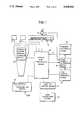
- FIG. 1is a block diagram illustrating a preferred embodiment of the present invention
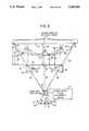
- FIG. 2is a diagrammatic view useful for explaining certain features of a specific exemplary embodiment of the invention.
- FIG. 3is a somewhat diagrammatic partial longitudinal sectional view for indicating the application of certain features of the present invention to an instant bar code reader generally as shown in U.S. Pat. No. 4,570,057;
- FIG. 4is a somewhat diagrammatic plan view illustrating an adaptive bar code image sensor system in accordance with the present invention, and also illustrating an alternative label guide indicator arrangement for the reader of FIG. 3;
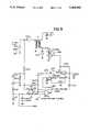
- FIGS. 5, 6 and 7are electric circuit diagrams for illustrating an exemplary implementation of component 11 of FIG. 1;
- FIGS. 6A through 6Fshow waveforms useful for explaining the operation of the circuit of FIG. 6;
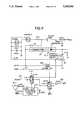
- FIGS. 8 and 9show an exemplary implementation of components 15, 16 and 17 of FIG. 1;
- FIG. 10is an electric circuit diagram for illustrating an exemplary implementation for component 121 in FIG. 1;
- FIGS. 11 and 12are diagrammatic illustrations for indicating an exemplary implementation of component 20 in FIG. 1;
- FIGS. 13 and 14illustrate examples of alternative arrangements in accordance with the invention.
- FIG. 1illustrates a preferred instant bar code reader system for extending the versatility of a commercial bar code reader such as shown in U.S. Pat. No. 4,570,057.
- Component 10, FIG. 1may represent a control and processing means for the system and may include a central processing unit, memory units and analog to digital conversion channels.
- the central processing unit and associated memoryform the main control portion of the system.
- the other functional blocks of FIG. 1may be inputs or outputs with respect to the central processing unit.
- the central processing unitmay be a microprocessor that executes the program to control the operation of the reader.
- the microprocessoracts as a microcontroller with the capability of sensing and controlling the functional elements of the bar code reader, and decoding the bar code as supplied from a bar code image sensor means 11.
- the readeris coupled on line with a host computer system, (for example by a host connection means in the form of a flexible cable), the decoded bar signal is transmitted to the host under the control of the central processing unit.
- the microprocessoris capable of static operation with shut-down for power conservation. Wake-up of the processor will occur when an operator actuates a scan switch 12.
- An electrically erasable read only memory of component 10may be utilized to store parameters and special modifiable decoding sequences for the bar code reader operation. Examples of these parameters would be label code, and input/output speed and control format.
- Component 10may also include a random access memory for data collection, decoding work space and buffer storage of the decoded label data for transmission to a host computer, for example.
- the random access memorycan be internal to the microprocessor chip or reside on a data bus.
- the analog/digital channelsare for receiving the bar code signals generated by the bar code image sensor means 11 and for other purposes as will be hereafter explained.
- the image sensor means 11may, for example, include a photosensor array indicated diagrammatically at 13 having a one dimensional linear array of photodiodes for detecting the bar code reflection image.
- the array 13may comprise five thousand photodiode circuits (5,000 pixels) and provide approximately three photodiode circuits (3 pixels) for each five mils (0.005 inch) of a bar code length. (Each pixel of array 13 may have a length of about seven microns.)
- a charge coupled device (CCD) shift registermay be arranged to receive bar code signal elements from the respective photodiode circuits after a suitable integration interval. Once the bar code signal elements have been transferred to the shift register, the signal elements are retained independently of further exposure of the photodiodes to reflected light from the bar code.
- CCDcharge coupled device
- an intensity sensor 14is provided and may comprise a photodiode that will determine the relative amount of light exposure of the photosensor array 13. If component 10 operates at sufficiently high speed, the signal from the intensity sensor 14 may be supplied exclusively to component 10 via an analog/digital channel so that the control and processing means can determine the optimum point for transfer of the bar code image signals to the shift register.
- the intensity sensor means 14is directly coupled with the hardware control circuits of the flashable illuminator means and of the bar code image sensor means, and this is indicated by dash lines L1 and L2 in FIG. 1; in this case, line L is used only so that the processor component 10 is advised that a flash has actually occurred.
- a component 16may effect interruption of the flow of current from the capacitor based directly on the signal supplied via L1 from intensity sensor 14. In this way, energy is conserved, and recharging of the capacitor speeded up.
- Component 16may comprise a flash current interrupter switch means, e.g., a solid state switch which is controlled to interrupt discharge of the capacitor of high voltage generation unit 17, and thus, to terminate the flash of light from the flashable illuminator 15 when intensity sensor 14 indicates that adequate reflected light has been received from a bar code.
- a flash current interrupter switch meanse.g., a solid state switch which is controlled to interrupt discharge of the capacitor of high voltage generation unit 17, and thus, to terminate the flash of light from the flashable illuminator 15 when intensity sensor 14 indicates that adequate reflected light has been received from a bar code.
- FIG. 2illustrates an exemplary configuration wherein the label guide indicator means 21 is provided by a pair of marker light emitting diodes 24 and 25 which produce light beams 26 and 27 extending from opposite ends of the photosensor array 13 through the lens system indicated at 30 so as to delineate by means of marker light spots at 28 and 29 on the label the field of view of the reader.
- FIG. 2illustrates a situation where label 31 has a bar code with a length greater than seven inches and is located at a distance D from a frontal window part 33 of the reader of greater than two inches, for example, three inches.
- flashable illuminator 15 of FIG. 1is illustrated as being implemented by two flash tubes 35 and 36 directed obliquely outwardly relative to a central axis 37 of the reader.
- FIG. 2also illustrates the provision of an ultrasonic transducer 38 for implementing component 22 of FIG. 1.
- transducer 38may emit an ultrasonic pulse along an axis 39 aligned with the reader central plane such that the time of arrival of a reflected pulse from the bar code label 31 provides a measure of reading distance.
- infrared distance measurement sensors 38-1 and 38-2are provided in FIG. 2, with axes arranged to intersect a curved label generally at a mean distance (e.g. at D o equal to one-half the sum of the maximum distance D1 and the minimum distance D11).
- adaptation means 20may include motor driven focus adjustment means 40 coupled with the lens system 30 for adjusting the lens system parallel to the central optical axis 37, as represented by the double-headed arrow 41.
- the readerhas a width dimension at its frontal wall which is greater than the extent of the exit light path at the plane of such frontal wall.
- marginal light rays 43 and 44 from the flash tubes 35 and 36are transmitted by transparent side walls 45 and 46 of the reader housing so that in this case the illumination field has a total extent at the plane of the reader frontal wall which is substantially greater than the width dimension of such frontal wall.
- a photodiode intensity sensor 50 corresponding to component 14 of FIG. 1is indicated as being mounted centrally as defined by a plane intersecting the optical axis 37, but offset from photosensor array 13 so as not to obstruct light incident thereon.
- Intensity sensor 50is preferably placed so as to intercept light of maximum intensity as reflected from the label 31.
- intensity sensorssuch as 50, 51 and 52 may be located at respective different locations adjacent sensor array 13 as indicated, and successive ones of the sensors may be selected for actual control of bar code image integration time during successive bar code reading operations for a given curved bar code configuration as will be hereafter explained.
- mirror elements 53 and 54are mounted at opposite ends of photosensor array 13 for reflecting light from the sources 24 and 25 along the beam paths 26 and 27.
- FIG. 3may be taken as supplementing FIG. 2, and corresponding reference numerals have been used in FIGS. 2 and 3 to designate similar parts.
- ultrasonic transducer 38may be located just above window 33 with its axis 39 directed generally parallel to the optical axis 64 (which indicates the axis for the reflected light entering the reader).
- the readeris shown as having transparent side wall portions such as 46 at the respective sides of the reader, corresponding to the transparent portions 45 and 46 in FIG. 2.
- Each of the flash lamp tubes 35 and 36may be provided with a housing 75 and an interior reflector 76 with a configuration as described as U.S. Pat. No. 4,570,057.
- the flash illumination means 35 and 36may effectively illuminate a sensing region having an extent greater than seven inches, for example.
- Reflected light from a bar code label 31follows an optical path as indicated at 64, 80, 81 and 60 in FIG. 3 by virtue of the arrangement of mirrors 82, 83 and 84. These mirrors are fixed relative to reader housing 86, while a lens barrel 90 carrying optical lenses is axially adjustable relative to the reader housing. Also preferably forming part of the adjustable lens barrel assembly 90 are an infrared rejecting filter 97 and a rectangular aperture element analogous to that of U.S. Pat. No. 4,570,057.
- barrel assembly 90is shown as having a series of gear teeth 101 meshing with a worm gear drive 102 which is driven from an adjustment motor 103 via a right angle drive coupling assembly 105.
- the barrel assembly 90may have a range of adjustment so as to accommodate bar code labels closely adjacent to the frontal window 33 and at progressively greater distances in front of the window 33 up to reading distances of at least three inches.
- a bearing for the shaft of worm gear 102is indicated at 111.
- Guide means for lens barrel 90are indicated as comprising flanges such as 112 for riding in cooperating slot-like low friction guideways such as 114.
- An alternative location for the light emitting diodes 24 and 25is indicated at 24-1 in FIG. 3.
- An analog to digital conversion channel of component 10, FIG. 1,may be utilized to monitor charge build-up in the high voltage generation component 17 so that a flash of the illuminator means 15 will take place only when the desired amount of flash driving current is available.
- intensity sensors 50, 51 and 52may read the light intensity values accumulated by intensity sensors 50, 51 and 52, so that such intensity values can determine respective bar code image integration times, where desired.
- Component 120 in FIG. 1represents-desired audio and visual status indicators for facilitating operation of the reader unit.
- a redlight-emitting diode indicatormay be energized whenever a thumb actuator controlling read enable switch 12 is pressed and the reading distance sensor means 22 determines that a bar code label is beyond the maximum reading distance of the reading distance adaptation means 20.
- the lens adjustment motor 103FIG. 3, may be disabled, e.g., by the programming of control and processing means 10 to conserve power.
- motor 103is essentially continuously controlled according to successive distance readings.
- means 120may produce a relatively long single beep and turn on a green light emitting indicator diode. Where a bad bar code reading situation is determined, e.g., after a selected number of reading attempts, means 120 may generate three short beeps, for example.
- the programmingmay be such that once a good reading or bad reading condition is determined, the user must release the thumb switch and depress it again to initiate another read sequence.
- Indicator lamps and a beeperhave been shown in the seventh figure of U.S. Pat. No. 4,570,057 and are described therein at column 11, lines 37-43.
- the indicator lightsmay be physically located forwardly of the thumb switch as can be seen in the first figure of U.S. Pat. No. 4,570,057.
- FIG. 1also indicates an input/output buffer component 121 for coupling the control and processing means 10 with a host processor or the like.
- a connection means 122may directly receive a host processor so that the host processor housing is physically attached with the reader housing.
- connection means 122may comprise a cable containing six conductors. Preferably, such a cable would be detachable at the reader. In this second example, all needed voltages may be generated in the reader from plus five volts supplied by two of the six conductors (+5 V, GND). The other four signal lines of the cable are preferably independently programmable as inputs or outputs.
- the host processormay be part of a portable hand held computer such as shown in U.S. Pat. Nos.
- the rechargeable batteries of the portable computermay supply all needed power to the reader unit of the present invention.
- a host computer unitcan be carried in a belt holster for example during extended use of the reader unit of the present invention.
- FIG. 4is a somewhat diagrammatic top plan view of an exemplary bar code image sensor means 11 such as indicated only schematically in FIG. 1.
- the sensor housing 124is shown as having a light transparent cover window 125 overlying the photodiode array 13.
- the intensity sensors 50, 51 and 52may each have a length of about one-tenth inch or more so as to span many bars of a reflected bar code image, e.g., at least six bar code elements, and reliably sense an average intensity value which is essentially independent of any specific bar code sequence.
- the intensity sensorsmay be cemented to the exterior surface of window 125 at successive locations along photodiode array 13 but offset from the light entrance path to the photodiode array.
- Mirrors 53 and 54, FIG. 2may be cemented in place on the glass 125 as indicated for mirrors 53' and 54' in FIG. 4.
- the light sources 24' and 25' in FIG. 4may be located in wall 130, FIG. 3, at a section as indicated 24-1 in FIG. 3.
- the mirrors 53' and 54'are secured at angles such that the marker beams will extend parallel to the image path at 60, 81, 80 and 64 and will produce spots of visible light, e.g., of red color, corresponding to spots 28 and 29 in FIG. 2, and spot 28 as indicated in FIG. 3.
- manual actuation of the read enable switch 12will initiate a flash of the illuminator means 15 provided the reader is within its operative range from a bar code label. If the reader is outside of such operative range, momentary actuation of the read enable switch 12 will activate a pair of marker beams such as 26, 27, FIG. 2 representing the lateral margins of the reader field of view. Then, if the reader is moved into operative range and the read enable switch 12 again actuated, the illuminator means 15 will be flashed regardless of the state of focus of the automatically adjustable lens means 30, FIG. 2.
- the marker beamswill automatically be turned on briefly to again delineate the reader field of view, and quickly thereafter the illuminator means will be flashed again. This sequence can be repeated automatically (if the read enable button is held depressed), until the lens means 30 has been automatically adjusted for the distance of the bar code from the reader and a valid reading is obtained.
- a plurality of reflected light intensity sensorssuch as 50, 51 and 52, FIG. 4, may be successively activated in successive flashes of the illuminator means 15, the intensity sensors automatically controlling successive integration times of the bar code image sensor 11, according to the average intensity of reflected light from respective different segments of the curved bar code.
- Respective segments of a curved bar code label 131have been indicated at 150, 151 and 152 in FIG. 2.
- intensity sensor 51might measure the reflected light from a bar code segment 151 on the label and cause transfer of the bar code image signals to a receiving means such as a CCD shift register after an integration time optimum for the reading of bar code segment 151.
- the intensity sensor 52might control integration time so as to be optimum for the bar code segment 152. Then in a third flash illumination of the bar code 131, the central intensity sensor 50 could control integration time.
- the control and processing means 10would then assemble readings for bar code segments 151, 152 and 150 from the successive flashes of illuminator means 15 to determine if a valid total reading had been obtained. If not, a further succession of three flashes of the illuminator means could be enabled, with the indicator beams 28, 29 being turned on in the interval while proper high voltage was building up for the further series of flashes. (Three capacitors of component 17, FIG. 1, could store charge and be discharged rapidly in succession to produce three flashes in rapid sequence without any delay for capacitor recharging).
- the processor 10could be programmed to flash both tubes 35 and 36 with the adjustment means 40 controlled according to the distance reading D2 as sensed by the distance measurement means 38. Thereafter, control of the adjustment means 40 would be related to a distance such as indicated as D22 in FIG. 2 so that marginal portions of the label 131-1 would then be in focus. With the new focus automatically established, tubes 35 and 36 could be again activated so as to read the marginal portions of the bar code on label 131-1, whereupon the processor component 10 could assemble the two readings pixel by pixel to establish a complete bar code.
- the readercould be provided with a display, and the processor component 10 could cause the display to instruct the operator that the label 131-1 was to be read in two segments, the reader first being positioned so as to be directed toward the left portion of the label 131-1, e.g., with only a tube 36 flashed, and then in a second operation, the reader being physically adjusted so as to be directed toward the right hand portion of label 131-1, and, for example, only the tube 35 flashed.
- the readercould be provided with a keyboard, and the operator noting the highly curved configuration of label 131-1, could advise the processor component 10 that a first reading would be taken of the left-hand portion of label 131-1, after which a separate reading would be taken from the right-hand portion of label 131-1.
- the processor 10could also take account of distance measurements from components 38, 38-1 and 38-2, in assembling e.g., pixel by pixel, a complete bar code from the successive readings.
- the reading distance sensor means 22will be activated to read the distance between the front window 33 of the reader and one or more regions of a bar code label. If the distance measured, such as D, FIG. 2, is greater than an operative range of the adaptation means 20, for example, greater than three inches, the adaptation means 20 may be disabled. Thus, for the case of adjustable lens means 30, the motor driven focus adjustment means 40 would be inactive as long as the distance sensor means such as 38 determined that the distance D was outside of the operative range of the lens means 30.
- the label guide indicator means 21would be active as long as the scan switch 12 was actuated by the operator, to produce the marker spots as indicated at 28 and 29 in FIG. 2 and as indicated at 28 in FIG. 3.
- the marker beams 26 and 27would remain on while switch 12 was actuated and for an interval of, for example, five seconds after release of switch 12, where the reading distance remained outside of the operative range.
- component 10checks the high voltage generation means 17 to determine if proper high voltage is present on the flash capacitor means and if so, turns off the label guide indicator means 21, FIG. 1, and effects a cleaning cycle of the bar code image sensor means 11 so as to prepare the photosensor array 13 for a reading operation.
- the processor component 10then initiates a capacitor discharge to activate the flashable illumination means 15.
- a single capacitormay be arranged to drive both of the flash tubes 35 and 36 of FIG. 2.
- respective individual capacitorsmay be arranged to drive the respective tubes 35 and 36. In one mode, both capacitors may be discharged to drive both of the tubes 35 and 36 simultaneously.
- an intensity sensor 50may control the duration of the integration time interval during which the reflected bar code image signal is accumulated at the sensor means 11.
- the bar code image signalsare transferred for example to a CCD shift register for readout from the sensor means 11.
- the signals received by the shift registerare not affected by further light impinging on the photodiode array 13.
- the flash current interrupter switch 16may be actuated so as to interrupt discharge from the relevant capacitor or capacitors. In this way, energy is conserved, and recharging of the capacitor means is speeded up.
- a capacitor associated with flash tube 35may be activated during a first reading interval under the control of an intensity sensor 51 for insuring an optimum reading of a bar code segment such as indicated at 151 of a label 131, for example, of marked curvature.
- the capacitor associated with flash tube 36may be activated to illuminate particularly a bar code segment 152, with the integration time of the bar code image sensor means being under the control of an intensity sensor 52 arranged to receive reflected light particularly from bar code segment 152.
- intensity sensor 51would be arranged to generate an average light value by averaging reflected light emanating from a portion 191 of segment 151.
- intensity sensor 52would receive light from a portion such as 192 of segment 152 where reflected light intensity would be greatest on the average.
- the programming of component 10would be such as to generate the bar code from two successive flashes, one of tube 35 and the other of tube 36. Where the bar code generated based on two such reading intervals fails to provide a valid consistent reading for central segment 150, component 10 could be programmed to produce in a third reading interval, the simultaneous discharge of both capacitors to simultaneously activate both of the flash tubes 35 and 36 under the control of the central intensity sensor 50 which sensor 50 would receive light from a portion 190 of segment 150 which would be expected to provide maximum average light intensity. The component 10 could then be programmed to assemble a complete bar code reading from the three successive reading intervals.
- the third intervalmight be driven by means of a third capacitor connectable to both tubes 35 and 36 so that the three reading intervals could be executed in quick succession.
- component 10may be programmed to immediately turn on the label guide indicator means 21 during the interval when the capacitor means is being automatically recharged for a succeeding second reading operation.
- the label guide indicator means 21will remain on, and the reading distance sensor means 22 will repeatedly measure the distance to the bar code label with an essentially continuous corresponding control of the lens means 30 by the focus adjustment means 40.
- the image sensor means 11will be again cleared and a new reading operation automatically carried out.
- one or more of the intensity sensors 50, 51 and 52determines the time point at which the image signal of the photodiode charge cells is transferred to the CCD shift register stages. Also, after the appropriate integration interval or intervals, the current interrupter switch 16 for a respective capacitor discharge circuit is operated to terminate the capacitor discharge and extinguish the flash of a respective illuminator means. The data resulting from each integration interval is transferred out of the image sensor means 11 via the CCD shift register for processing in component 10.
- the corresponding indicator of component 120When a successful reading is determined by component 10, the corresponding indicator of component 120 will be activated, and for example, it will be necessary to release switch 12 before a further reading operation can be initiated.
- the programming of component 10may be such that the reading operation is automatically repeated up to, for example, ten times. Should ten successive reading attempts be unsuccessful, component 10 would produce the corresponding bad read condition indication via component 120, and again, for example, it might be necessary for the operator to release switch 12 before a further read sequence could be initiated.
- the programmingcould be such that component 10 could establish communication with a host computer system, for example, an accompanying portable computer, or an integral host computer. Where no further actuation of the switch 12 occurs after a valid reading, the system may be programmed to automatically power down so that a battery means, for example, within reader housing 86, would be subject to the minimum drain during inactive intervals of the reader system.
- the foregoing modes of operationcould be selected, for example, from the keyboard of a hand-held computer carried by the operator along with the reader unit.
- the various optional modes of operationcould be correspondingly selected with all modes preprogrammed into the component 10, or desired respective modes of operation could be obtained by loading the corresponding programming from the hand-held computer into component 10, as desired.
- Other special modes of operationcan be accommodated such as machine gun scanning (which might be used in reading lists of labels).
- switch 12could be held depressed while the reader was moved over a series of labels, and the programming would be such as to discard identical adjacent bar code readings.
- changescould be effected in the operation of the good and bad read indicators of component 120 and changes could be made in the allowed number of retries and the like.
- component 10may be implemented as a Motorola MC68HC11 microcontroller.
- Other processor componentswhich are presently commercially available include a NEC uPD78310, a National HPC16140, an Intel CMOS MCS8097, and a Hitachi HD64180. Some such components would need more external devices than others, e.g., such as analog to digital conversion channels, ROM, RAM, EEPROM (or equivalent non-volatile RAM), etc.
- FIGS. 5, 10, 11 and 12 hereinare shown as using signals from the Motorola MC68HC11. All other inputs and outputs are general processor pins, so that a drawing showing the processor of component 10 is not necessary.
- reference numeral 11-1indicates a specific component for use in the bar code image sensor means 11 of FIG. 1.
- component 11-1may comprise a solid state integrated circuit chip such as type TCD106C image sensor or the equivalent.
- Component 11-1includes a charge coupled device (CCD) shift register driven for example utilizing two megahertz clock signals from driver components 201, 202 and 203. Where components 201-203 are implemented as type 75361 drivers, these components serve to convert the five volt input logic signals to the twelve volt level needed to drive component 11-1.
- Current sources 205 and 206 in conjunction with resistors 207 and 208provide a DC offset to bring the video output levels from the shift registers into an acceptable input range for the analog to digital converter channels A/D3 and A/D4 of component 10.
- the microcontroller of component 10could drive each signal line 211-215 directly, but the bit manipulation capabilities of most presently available processors would provide a very slow preparation and reading cycle time for the case of a bar code image sensor size of 5000 pixels.
- the circuit shown in FIG. 5uses an eight megahertz clock 220, FIG. 6, to produce a controlling sequence which can clock out two pixels every microsecond from component 11-1.
- the circuit of FIG. 6allows continuous operation such as is needed to quickly prepare the component 11-1 for a reading operation and also allows single-stepping operation to give the analog to digital converter channels sufficient time to input each pixel.
- the circuit of FIG. 6allows each shift pulse to be synchronized with the clock rate at line 215, FIG. 5, (the 01 clock line) for proper operation.
- FIG. 6reference characters 6A through 6F have been applied to various lines and the corresponding related waveforms have been indicated in FIGS. 6A through 6F, respectively, by way of explanation of the operation of FIG. 6.
- the outputs of FIG. 6form respective inputs to drivers 201203 of FIG. 5 as indicated by the respective designations of the corresponding lines in these figures.
- reference numeral 231indicates the first positive transition of the clock waveform after the signal CONT (supplied by the aforementioned MC68HC11 microcontroller) goes low, or the signal line SCYC goes high.
- the signal SHfollows the dash line 232 if the signal SHEN is true. As indicated at 241-244 by dash lines, the cycling continues if the signal CONT remains low.
- Component 11-1requires twelve volts for proper operation and a circuit for providing this voltage from the five volt supply available is indicated in FIG. 7. This circuit should be able to be powered down when not in use in order to conserve power.
- a drawback of the circuit of FIG. 7is that when it is turned off, the inductor L1 provides plus five volts to the plus twelve volt circuits unless a transistor Q4 is added to block the five volts.
- Line 251 in FIG. 7receives a switched plus five volts for supply to the drivers 201-203 of FIG. 5. Line 251 may also supply five volts to any other circuit which is not needed when the twelve volts is off.
- the five volts at line 251is switched off with the plus twelve volts at line 252 to completely power down the image sensor component 11-1 of FIG. 5 and drivers 201-203.
- An output line 253 in FIG. 7provides five volts when the twelve volts are shut off and provides twelve volts when the line 254 (+(+12ENB)) is enabled.
- the voltage at line 253is used to drive an oscillator 255 of FIG. 8 which is utilized in the present commercial instant bar code reader. Circuits suitable for implementing FIG. 7 desirably exhibit low cost, high efficiency and least number of parts.
- FIG. 8illustrates a suitable high voltage generator circuit for generating approximately 300 volts for the xenon flash tube 260 illustrated in FIG. 9.
- the circuit shown in FIG. 8is similar to that of the present commercial instant bar code reader.
- the transformer T1 of FIG. 8uses a gapped core and is actually a transforming inductor. Magnetic energy is stored in the core on respective first half cycles, and on opposite half cycles the field collapses and generates very high secondary voltages which are used to charge the flash capacitor 261.
- transformer T1may be a Ferroxcube 1408 PA 250-3B7 with a turns ratio of forty-three to one. Transformer T1 exhibits a 100 microhenry inductance at its primary side and 185 millihenries on the secondary side.
- This type of circuitwill continue to charge the capacitor 261 beyond its rating, if not stopped, so a comparator 262 is used to control the oscillator 255.
- the output of comparator 262 at 263is a logic signal that indicates to component 10 that proper flash voltage is available.
- the five-twelve volt supply line 253is used to energize oscillator 255 in the circuit of the present commercial instant bar code reader since the oscillator component 255 drives transistor 266 more efficiently when running from twelve volts.
- the flash capacitor charging circuitmust also run from plus five volts.
- the circuit of the present commercial instant bar code readerprovides a relatively high initial input current of up to two amperes during charging of capacitor 261.
- component 10may be programmed to control the charge rate to allow the lowest current level, for example, a charge rate of 250 milliamperes over a charging interval of 250 milliseconds could be switched on by the programming where a flash rate of four times per second would be acceptable.
- Much of the flash tube illumination circuit shown in FIG. 9is used in the present commercial version of instant bar code reader.
- component 16-1 corresponding to flash current interrupter switch 16, FIG. 1is advantageous to interrupt the flash when sufficient light has been detected by the intensity sensor means 14.
- the flash capacitorsuch as 261, FIG. 8, will be drained, producing additional unneeded light.
- the capacitorwill have to be recharged from zero requiring that much more current and elapsed time.
- intensity sensor means 14 and switch means 16not only reduces the power requirement so as to increase the operational time of the system in portable applications using batteries, but also enhances the performance of the unit by enabling more rapid flashes of the illuminator means.
- Input 270 (FLASH VOLTAGE DISABLE) FIG. 8, and input 271 CONT and input 271' (FLASH), FIG. 9,can be controlled from component 10.
- FIG. 9illustrates a light sensor means 14-1 corresponding to intensity sensor means 14, FIG. 1, as being coupled with the switch 16-1 and the illuminator means indicated generally at 15-1 by means of a hardware circuit which can be trimmed for example, as indicated by variable resistance means 272 associated with conversion circuit and timer component 273.
- the circuit of FIG. 9not only causes a "set" output pulse at 275, FIG. 9, to initiate the shift sequence in the CCD component 11-1, FIG. 5, via input 275-1, FIG.
- component 16-1which may, for example, be a Motorola Gemfet, type MGP20N50.
- Component 16-1needs to be able to handle the forty amperes peak during discharge of capacitor 261.
- the microcontroller of component 10, FIG. 1may be connected to a host computer with a six conductor shielded, coiled cable such as indicated at 122, FIG. 1, by means of circuitry, such as shown in FIG. 10.
- the shieldshould be a braid or spiral wrapped type, but not a foil with a drain wire. Each wire should have a number of twists per inch to give it maximum flexibility.
- the other two lines 285 and 286are power (plus 5 V) and signal ground.
- FIG. 10shows Fairchild type 74AC14 devices as being utilized for buffer and receiver components 291-295. This component was used because of its built-in hysteresis and balanced high output drive (24 mA) capability. The various resistors and diodes are used for ESD (electrostatic discharge) protection up to 25,000 volts. A six-pin connector may be used at 296 of a style similar to that used on industrial camera cables.
- FIG. 11shows an implementation 20-1 of the automatic reading distance adaptation means of FIG. 1.
- a DC motor 103-1is controlled from the microcontroller of component 10 via power drivers 302 and 303.
- the drivers 302 and 303are selectively energized so as to drive the motor 301 in the correct direction for improving focus.
- a feedback transducer 305is shown as having a movable tap 306 mechanically coupled with the focus barrel 30 and thus being driven jointly therewith by motor 103-1 so that analog to digital converter channel A/D 2 receives a resistance value in accordance with the actual adjusted position of the optics 30.
- FIG. 12shows an implementation 22-1 of reading distance sensor means 22 including an ultrasonic distance measurement circuit 310 associated with ultrasonic transducer 38.
- a disable line 311 (DENB) for the circuit 310may be controlled by the microprocessor component 10 of FIG. 1, and the analog distance measurement value may be supplied via output line 312 to an analog to digital converter channel A/D 1. All parameter and calibration/conversion tables for the ultrasonic distance measurement can reside in the memory of component 10.
- the audio indicator of component 120can be driven from a frequency created by the processor of component 10, if desired. All light emitting diode indicators are controlled by the processor as indicated in FIG. 1.
- the switch 12connects to a processor input pin but should be able to interrupt and wake up the processor if the reader is in a standby/sleep mode.
- Label guide indicator means 21preferably provides two indicator beams as previously described, it being conceivable to produce the two beams from a single light emitting diode which is directed initially to a partially reflecting mirror which is also partially transmissive along the length of the photosensor array 13 to a completely reflective mirror at the opposite end of the array.
- the marker light emitting diode or diodesare turned off during the clearing of the image sensor and the energization of the flashable illuminator means to prevent their saturating the image sensor with light and thus interfering with an accurate bar code reading.
- the reader housing 10may accommodate a plurality of adjustable lens means with respective overlapping depths of field so that for fixed positions of the lens means, the depth of field is greatly enlarged.
- Such multiple lens barrelscould be adjusted simultaneously so that the lens systems in each position thereof have the total depth of field greatly enlarged.
- mirror 82, FIG. 3could have an upper segment bent oppositely to the segment receiving an image at axis 64, so that a second bundle of reflected light would be directed upwardly as viewed in FIG.
- FIG. 13diagrammatically illustrates the optical components of such an arrangement, which includes a window 33A, a flash tube housing 75A, a mirror segment 82A, a mirror 83A, a mirror 84A, a lens barrel 90A, and a sensor housing 124A, respectively, corresponding to components 33, 75, 82, 83, 84, 90, and 124 of the arrangement of FIG. 3, and providing optical axes 60A and 64A and paths 80A and 81A, respectively, corresponding to paths 60 and 64 and paths 80 and 81 of FIG. 3.
- the arrangementalso includes an upper mirror segment 82B bent oppositely to the segment 82A and receiving an image at an axis 64B to direct light upwardly to a mirror 83B having an inclination opposite to that of the mirror 83A.
- a second imageis directed rearwardly along an axis 81B parallel to axis 81A to pass through a second lens barrel 90B located rearwardly with respect to barrel 90A so as to focus on bar code images closer to the window 33A.
- One dimensional photosensor arrays 13A and 13B within sensor housing 124A and 124Bare connected to control and processing means 10A.
- Distance measurement means 38may be coupled with control and processor means 10A in order to provide range information to processor 10A such that the proper focal path A or B may be selected. This may be accomplished by simply allowing the processor 10A to operatively select a particular one-dimensional array (124A, 124B).
- a plurality of mirrors analogous to mirror 82could be arranged at respective different distances from the window 33, such that all of the image paths would traverse the same lens barrel 90 but then would be focused onto respective different image sensors, for example, by means of multiple mirrors analogous to mirror 84 but located at respective different distances from the center of lens barrel 90.
- Such a multiple image path lens systemwould, for example, provide paths within the reader of length greater than the length of the image path at 64, 80, 81, 60 of FIG. 3, and also optical image paths in the housing 86 of length shorter than the length of the path 64, 80, 81, 60.
- the various image paths togethercould provide the result that the depth of field for each respective image path would overlap with the depth of field of other of the image paths, so that the single lens barrel such as 90 would cover images anywhere within a range in front of a window 33 corresponding to a multiple of the depth of field provided by the image path 64, 80, 81, 60 by itself.
- a common lens barrel assemblycould focus on multiple depths in front of the reader, the processor component 10 selecting the respective image sensor or image sensors from which to assemble the pixels of a complete bar code reading.
- FIG. 14diagrammatically illustrates the optical components of such a multiple image path single lens system, which includes a window 33C, flash tube housing 75C, mirror 83C, mirror 84C, lens barrel 90C and sensor housing 124C, corresponding to components 33, 75, 83, 84, 90 and 124 of FIG. 3 and components 33A, 75A, 83A, 84A, 90A and 124A of FIG. 13.
- the system of FIG. 14diagrammatically illustrates the optical components of such a multiple image path single lens system, which includes a window 33C, flash tube housing 75C, mirror 83C, mirror 84C, lens barrel 90C and sensor housing 124C, corresponding to components 33, 75, 83, 84, 90 and 124 of FIG. 3 and components 33A, 75A, 83A, 84A, 90A and 124A of FIG. 13.
- the 14further includes a plurality of mirrors 82C, 82D, 82E, 82F and 82G at respective different distances from the window 33C, such that all image paths traverse the same lens barrel 90C, to be focused on different image sensors of an array 13C which are within a housing 124C and which are connected to control and processing means 10C operative to select the respective image sensor or image sensors from which to select the pixels of a complete bar code reading.
- distance measurement means 38may be coupled with control and processor means 10C in order to provide range information to processor 10C such that the proper focal path C, D, E, F, or G may be selected. This may be accomplished by simply allowing the processor 10C to operatively select a particular line 13C of the two-dimensional array 124C.
Landscapes
- Physics & Mathematics (AREA)
- Engineering & Computer Science (AREA)
- Electromagnetism (AREA)
- General Physics & Mathematics (AREA)
- Theoretical Computer Science (AREA)
- Health & Medical Sciences (AREA)
- General Health & Medical Sciences (AREA)
- Toxicology (AREA)
- Artificial Intelligence (AREA)
- Computer Vision & Pattern Recognition (AREA)
- General Engineering & Computer Science (AREA)
- Image Input (AREA)
Abstract
Description
Claims (12)
Priority Applications (13)
| Application Number | Priority Date | Filing Date | Title |
|---|---|---|---|
| US07/947,036US5308966A (en) | 1986-08-08 | 1992-09-16 | Hand-held instant bar code reader having automatic focus control for operation over a range of distances |
| US08/040,313US5468947A (en) | 1986-08-08 | 1993-03-29 | Pocket size data capture unit with processor and shell modules |
| US08/215,112US5640001A (en) | 1986-08-08 | 1994-03-17 | Hand-held instant bar code reader having automatic focus control for operation over a range of distances |
| US08/309,334US5576529A (en) | 1986-08-08 | 1994-09-19 | Hand-held optically readable information set reader focus with operation over a range of distances |
| US08/438,220US5834753A (en) | 1986-08-08 | 1995-05-09 | Laser scanner module having integral interface with hand-held data capture terminal proximity and label sensing, and enhanced sensitivity and power efficiency |
| US08/448,169US5892971A (en) | 1986-08-08 | 1995-05-23 | Portable data processing device having an indicia reader and a multi-tasking operating system capable of executing battery monitoring instructions while concurrently executing application programs |
| US08/452,475US5895906A (en) | 1986-08-08 | 1995-05-26 | Hand-held data capture system with processor module and detachable second module |
| US08/751,381US5804805A (en) | 1986-08-08 | 1996-11-19 | Hand-held optical indicia reader having a controlled oscillating system for optimal indicia reading |
| US08/751,382US5837987A (en) | 1986-08-08 | 1996-11-19 | Hand-held optically readable character set reader having automatic focus control for operating over a range of distances |
| US08/877,243US5969321A (en) | 1986-08-08 | 1997-06-17 | Hand-held optically readable information set reader with operation over a range of distances |
| US08/946,048US5914481A (en) | 1986-08-08 | 1997-10-07 | Portable data collection terminal with handwritten input area |
| US09/192,033US6138915A (en) | 1986-08-08 | 1998-11-13 | Hand-held optically readable character set reader having automatic focus control for operation over a range of distances |
| US11/352,441US20070007353A1 (en) | 1986-08-08 | 2006-02-08 | Laser scanner module having integral interface with hand-held data capture terminal, proximity and label sensing, and enhanced sensitivity and power efficiency |
Applications Claiming Priority (4)
| Application Number | Priority Date | Filing Date | Title |
|---|---|---|---|
| US06/894,689US4877949A (en) | 1986-08-08 | 1986-08-08 | Hand-held instant bar code reader system with automated focus based on distance measurements |
| US42205289A | 1989-10-16 | 1989-10-16 | |
| US87579192A | 1992-04-27 | 1992-04-27 | |
| US07/947,036US5308966A (en) | 1986-08-08 | 1992-09-16 | Hand-held instant bar code reader having automatic focus control for operation over a range of distances |
Related Parent Applications (1)
| Application Number | Title | Priority Date | Filing Date |
|---|---|---|---|
| US87579192AContinuation | 1986-08-08 | 1992-04-27 |
Related Child Applications (2)
| Application Number | Title | Priority Date | Filing Date |
|---|---|---|---|
| US08/040,313Continuation-In-PartUS5468947A (en) | 1986-08-08 | 1993-03-29 | Pocket size data capture unit with processor and shell modules |
| US08/215,112Continuation-In-PartUS5640001A (en) | 1986-08-08 | 1994-03-17 | Hand-held instant bar code reader having automatic focus control for operation over a range of distances |
Publications (1)
| Publication Number | Publication Date |
|---|---|
| US5308966Atrue US5308966A (en) | 1994-05-03 |
Family
ID=27411333
Family Applications (1)
| Application Number | Title | Priority Date | Filing Date |
|---|---|---|---|
| US07/947,036Expired - LifetimeUS5308966A (en) | 1986-08-08 | 1992-09-16 | Hand-held instant bar code reader having automatic focus control for operation over a range of distances |
Country Status (1)
| Country | Link |
|---|---|
| US (1) | US5308966A (en) |
Cited By (100)
| Publication number | Priority date | Publication date | Assignee | Title |
|---|---|---|---|---|
| US5448078A (en)* | 1993-01-11 | 1995-09-05 | Sumitomo Electric Industries, Ltd. | Bar code or optical data reader which adjusts focal length based on detected distance to coded surface |
| US5473149A (en)* | 1993-05-25 | 1995-12-05 | Nippondenso Co., Ltd. | Bar code reading apparatus with multifocal length optical system |
| US5485263A (en)* | 1994-08-18 | 1996-01-16 | United Parcel Service Of America, Inc. | Optical path equalizer |
| US5530233A (en)* | 1994-06-30 | 1996-06-25 | Symbol Technologies, Inc. | Bar code scanner with quasi-retroreflective light collection |
| US5534684A (en)* | 1994-08-30 | 1996-07-09 | Norand Corporation | Portable optical reader with motion sensing system and method |
| US5572006A (en)* | 1994-07-26 | 1996-11-05 | Metanetics Corporation | Automatic exposure single frame imaging systems |
| US5576529A (en)* | 1986-08-08 | 1996-11-19 | Norand Technology Corporation | Hand-held optically readable information set reader focus with operation over a range of distances |
| US5581071A (en)* | 1994-12-06 | 1996-12-03 | International Business Machines Corporation | Barcode scanner with adjustable light source intensity |
| US5616909A (en)* | 1995-06-06 | 1997-04-01 | Intermec Corporation | Method and apparatus for maintaining a scanning optical path length within a predetermined range |
| US5633487A (en)* | 1995-12-15 | 1997-05-27 | Adaptive Optics Associates, Inc. | Multi-focal vision system |
| US5635700A (en)* | 1994-07-27 | 1997-06-03 | Symbol Technologies, Inc. | Bar code scanner with multi-channel light collection |
| US5640001A (en)* | 1986-08-08 | 1997-06-17 | Norand Technology Corporation | Hand-held instant bar code reader having automatic focus control for operation over a range of distances |
| US5702059A (en)* | 1994-07-26 | 1997-12-30 | Meta Holding Corp. | Extended working range dataform reader including fuzzy logic image control circuitry |
| US5714745A (en)* | 1995-12-20 | 1998-02-03 | Metanetics Corporation | Portable data collection device with color imaging assembly |
| US5715831A (en)* | 1996-06-21 | 1998-02-10 | Desert Moon Development Limited Partnership | Calibrated air tube for spirometer |
| US5763864A (en)* | 1994-07-26 | 1998-06-09 | Meta Holding Corporation | Dataform reader including dual laser and imaging reading assemblies |
| US5783811A (en)* | 1995-06-26 | 1998-07-21 | Metanetics Corporation | Portable data collection device with LED targeting and illumination assembly |
| US5793033A (en)* | 1996-03-29 | 1998-08-11 | Metanetics Corporation | Portable data collection device with viewing assembly |
| US5796089A (en)* | 1995-09-21 | 1998-08-18 | Symbol Technologies, Inc. | Bar code scanner with simplified auto-focus capability |
| US5798516A (en)* | 1996-05-28 | 1998-08-25 | Accu-Sort Systems, Inc. | Focusing mechanism for hand-held CCD scanners |
| US5811774A (en)* | 1994-07-26 | 1998-09-22 | Metanetics Corporation | Extended working range dataform reader with reduced power consumption |
| US5811784A (en)* | 1995-06-26 | 1998-09-22 | Telxon Corporation | Extended working range dataform reader |
| US5818028A (en)* | 1995-06-26 | 1998-10-06 | Telxon Corporation | Portable data collection device with two dimensional imaging assembly |
| US5874719A (en)* | 1995-06-08 | 1999-02-23 | Erwin Sick GmbH Optik-- Elektronik | Method and apparatus for distance measurement |
| US5892543A (en)* | 1995-06-05 | 1999-04-06 | United Parcel Service Of America, Inc. | Imaging system including an auto zoom controller |
| US5898166A (en)* | 1995-05-23 | 1999-04-27 | Olympus Optical Co., Ltd. | Information reproduction system which utilizes physical information on an optically-readable code and which optically reads the code to reproduce multimedia information |
| US5912447A (en)* | 1997-01-14 | 1999-06-15 | United Parcel Service Of America, Inc. | Concentric optical path equalizer with radially moving mirrors |
| US5914477A (en)* | 1996-06-26 | 1999-06-22 | Ncr Corporation | Line focus barcode scanner |
| US5945661A (en)* | 1995-06-02 | 1999-08-31 | Asahi Kogaku Kogyo Kabushiki Kaisha | Data symbol reader and method including data symbol position evaluation |
| US5969321A (en)* | 1986-08-08 | 1999-10-19 | Norand Corporation | Hand-held optically readable information set reader with operation over a range of distances |
| US5984186A (en)* | 1997-10-29 | 1999-11-16 | Psc Inc. | CCD-base bar code scanner |
| US5997483A (en)* | 1996-06-21 | 1999-12-07 | Desert Moon Development Limited Partnership | Individualized and calibrated air tube for spirometer |
| US6000612A (en)* | 1997-10-10 | 1999-12-14 | Metanetics Corporation | Portable data collection device having optical character recognition |
| US6006990A (en)* | 1995-09-12 | 1999-12-28 | Telxon Corporation | Dataform reader utilizing hand jittering compensation method |
| US6024283A (en)* | 1995-02-27 | 2000-02-15 | Symbol Technologies, Inc. | Bar code readers having selectable optical elements |
| US6053408A (en)* | 1997-12-02 | 2000-04-25 | Telxon Corporation | Multi-focal length imaging based portable dataform reader |
| US6053409A (en)* | 1996-03-07 | 2000-04-25 | Accu-Sort Systems, Inc. | Dynamic focusing apparatus for an optical imaging system using a deformable mirror |
| US6123261A (en)* | 1997-05-05 | 2000-09-26 | Roustaei; Alexander R. | Optical scanner and image reader for reading images and decoding optical information including one and two dimensional symbologies at variable depth of field |
| US6179208B1 (en) | 1997-01-31 | 2001-01-30 | Metanetics Corporation | Portable data collection device with variable focusing module for optic assembly |
| US6234396B1 (en)* | 1996-02-20 | 2001-05-22 | Opticon, Inc. | Optical pattern reading apparatus |
| US6296187B1 (en) | 1999-11-12 | 2001-10-02 | Psc Inc. | CCD-based bar code scanner |
| US6318635B1 (en)* | 1997-12-02 | 2001-11-20 | Telxon Corporation | Multi-focal length imaging based portable dataform reader |
| US6340114B1 (en)* | 1998-06-12 | 2002-01-22 | Symbol Technologies, Inc. | Imaging engine and method for code readers |
| US6422467B2 (en)* | 1995-12-18 | 2002-07-23 | Metrologic Instruments, Inc. | Reading system a variable pass-band |
| US6424830B1 (en) | 1994-07-26 | 2002-07-23 | Telxon Corporation | Portable data collection network with telephone and voice mail capability |
| US20030121978A1 (en)* | 2000-07-14 | 2003-07-03 | Rubin Kim T. | Compact matrix code and one-touch device and method for code reading |
| US6619550B1 (en)* | 1995-12-18 | 2003-09-16 | Metrologic Instruments, Inc. | Automated tunnel-type laser scanning system employing corner-projected orthogonal laser scanning patterns for enhanced reading of ladder and picket fence oriented bar codes on packages moving therethrough |
| US6629639B2 (en)* | 1996-12-30 | 2003-10-07 | Datalogic S.P.A. | Method and machine for reading and assigning optical codes |
| US20030201327A1 (en)* | 2002-04-30 | 2003-10-30 | Mehrban Jam | Variable focal length imaging device |
| US20040118927A1 (en)* | 2002-12-18 | 2004-06-24 | Alex Breytman | Miniature auto focus voice coil actuator system |
| US20040118919A1 (en)* | 2002-12-18 | 2004-06-24 | Alex Breytman | Image scanning device having a system for determining distance to a target |
| US20040118918A1 (en)* | 2002-12-18 | 2004-06-24 | Paul Dvorkis | Imaging optical code reader having selectable depths of field |
| US20040118926A1 (en)* | 2002-12-18 | 2004-06-24 | Dmitriy Yavid | System and method for auto focusing an optical code reader |
| US20040129783A1 (en)* | 2003-01-03 | 2004-07-08 | Mehul Patel | Optical code reading device having more than one imaging engine |
| US20040262396A1 (en)* | 1994-03-04 | 2004-12-30 | Andrew Longacre | Optical reader having two-dimensional solid state image sensor and light generator |
| US20050023351A1 (en)* | 2003-08-01 | 2005-02-03 | Mehul Patel | Imaging and illumination engine for an optical code reader |
| US20050023352A1 (en)* | 2003-08-01 | 2005-02-03 | Mehul Patel | Imaging and illumination engine for an optical code reader |
| US20060043194A1 (en)* | 2004-08-31 | 2006-03-02 | Edward Barkan | Scanner and method for eliminating specular reflection |
| US20060132639A1 (en)* | 2004-12-21 | 2006-06-22 | Symagery Microsystems Inc. | Dual mode image engine |
| US20070063043A1 (en)* | 2005-09-21 | 2007-03-22 | Intermec Ip Corp. | Optoelectronic reader and method for reading machine-readable symbols |
| US20070090191A1 (en)* | 2000-11-24 | 2007-04-26 | Schnee Michael D | Imaging engine employing planar light illumination and linear imaging |
| EP1804192A1 (en)* | 2005-12-30 | 2007-07-04 | DATALOGIC S.p.A. | Optical code reader |
| US20070164115A1 (en)* | 2006-01-17 | 2007-07-19 | Symboltechnologies, Inc. | Automatic exposure system for imaging-based bar code reader |
| US20070170259A1 (en)* | 2006-01-25 | 2007-07-26 | Laurens Nunnink | Method and apparatus for providing a focus indication for optical imaging of visual codes |
| US7483417B2 (en) | 1996-04-18 | 2009-01-27 | Verizon Services Corp. | Telephony communication via varied redundant networks |
| US7505785B2 (en) | 1993-10-13 | 2009-03-17 | Dataquill Limited | Data entry systems |
| US20090127342A1 (en)* | 2007-11-20 | 2009-05-21 | Symbol Technologies, Inc. | Imaging Bar Code Reader with Illumination Control System |
| US20090206161A1 (en)* | 2008-02-12 | 2009-08-20 | Datalogic Scanning, Inc. | Systems and methods for forming a composite image of multiple portions of an object from multiple perspectives |
| US20100006742A1 (en)* | 2005-11-16 | 2010-01-14 | Accu-Sort Systems, Inc. | Large depth of field line scan camera |
| US7664097B2 (en) | 1996-04-18 | 2010-02-16 | Verizon Services Corp. | Telephone service via networking |
| USRE41349E1 (en)* | 1998-06-01 | 2010-05-25 | Datalogic S.P.A. | Apparatus and method for reading an optical code |
| US20100147956A1 (en)* | 2008-12-16 | 2010-06-17 | Hand Held Products, Inc. | Indicia reading terminal including frame processing |
| US20100163628A1 (en)* | 2008-02-12 | 2010-07-01 | Datalogic Scanning, Inc. | Two-plane optical code reader for acquisition of multiple views an object |
| US20100163627A1 (en)* | 2008-12-26 | 2010-07-01 | Datalogic Scanning, Inc. | Image-based code reader for acquisition of multiple views of an object and methods for employing same |
| US20100163626A1 (en)* | 2008-12-26 | 2010-07-01 | Datalogic Scanning, Inc. | Data reader having compact arrangement for acquisition of multiple views of an object |
| US20100163622A1 (en)* | 2008-02-12 | 2010-07-01 | Datalogic Scanning, Inc. | Monolithic mirror structure for use in a multi-perspective optical code reader |
| US20100213259A1 (en)* | 2009-02-20 | 2010-08-26 | Datalogic Scanning, Inc. | Systems and methods of optical code reading using a color imager |
| US7813332B1 (en) | 1997-03-19 | 2010-10-12 | Verizon Services Corp. | Voice call alternative routing through PSTN and internet networks |
| US7817619B1 (en) | 1996-12-18 | 2010-10-19 | Verizon Services Corp. | Internet long distance telephone service |
| US7830860B2 (en) | 1997-03-11 | 2010-11-09 | Verizon Services Corp. | Packet data network voice call quality monitoring |
| US7835344B1 (en) | 1997-03-19 | 2010-11-16 | Verizon Services Corp. | Transport of caller identification information through diverse communication networks |
| CN101999128A (en)* | 2008-02-12 | 2011-03-30 | 数据逻辑扫描公司 | Systems and methods for forming a composite image of multiple portions of an object from multiple perspectives |
| US7948968B2 (en) | 1997-09-16 | 2011-05-24 | Verizon Communications Inc. | Network session management |
| US7957554B1 (en) | 2002-12-31 | 2011-06-07 | Cognex Technology And Investment Corporation | Method and apparatus for human interface to a machine vision system |
| US20110297748A1 (en)* | 2009-01-15 | 2011-12-08 | Eth Zurich | Method and portable apparatus for recognizing bar codes |
| US20110310289A1 (en)* | 2000-02-15 | 2011-12-22 | Accu-Sort Systems, Inc. | Automatic focusing camera with moving mirror between fixed lens and fixed image sensor |
| US8134116B2 (en) | 2009-01-12 | 2012-03-13 | Cognex Corporation | Modular focus system for image based code readers |
| US8302864B2 (en) | 2007-12-28 | 2012-11-06 | Cognex Corporation | Method and apparatus using aiming pattern for machine vision training |
| US8496173B2 (en)* | 2011-07-11 | 2013-07-30 | Sick Ag | Camera-based code reader and method for its adjusted manufacturing |
| US8646689B2 (en) | 2007-12-28 | 2014-02-11 | Cognex Corporation | Deformable light pattern for machine vision system |
| US8690063B2 (en)* | 2012-05-01 | 2014-04-08 | Symbol Technologies, Inc. | Apparatus for and method of electro-optically reading direct part marking indicia by image capture |
| US8724188B2 (en) | 2006-06-20 | 2014-05-13 | Datalogic ADC, Inc. | Imaging scanner with multiple image fields |
| US8938062B2 (en) | 1995-12-11 | 2015-01-20 | Comcast Ip Holdings I, Llc | Method for accessing service resource items that are for use in a telecommunications system |
| US9191505B2 (en) | 2009-05-28 | 2015-11-17 | Comcast Cable Communications, Llc | Stateful home phone service |
| US20160188942A1 (en)* | 2014-12-30 | 2016-06-30 | Hand Held Products, Inc. | Point-of-sale (pos) code sensing apparatus |
| US9746636B2 (en) | 2012-10-19 | 2017-08-29 | Cognex Corporation | Carrier frame and circuit board for an electronic device |
| US10067312B2 (en) | 2011-11-22 | 2018-09-04 | Cognex Corporation | Vision system camera with mount for multiple lens types |
| CN109254006A (en)* | 2018-10-30 | 2019-01-22 | 深圳市九天星科技发展有限公司 | A kind of laser physical evidence exploration instrument |
| US10498933B2 (en) | 2011-11-22 | 2019-12-03 | Cognex Corporation | Camera system with exchangeable illumination assembly |
| US11366284B2 (en) | 2011-11-22 | 2022-06-21 | Cognex Corporation | Vision system camera with mount for multiple lens types and lens module for the same |
Citations (4)
| Publication number | Priority date | Publication date | Assignee | Title |
|---|---|---|---|---|
| US4136821A (en)* | 1976-09-01 | 1979-01-30 | Nippondenso Co., Ltd. | Method and apparatus for recognizing code information |
| US4282425A (en)* | 1979-07-25 | 1981-08-04 | Norand Corporation | Instant portable bar code reader |
| US4422745A (en)* | 1981-07-31 | 1983-12-27 | National School Studios, Inc. | Camera system |
| US4500776A (en)* | 1982-11-08 | 1985-02-19 | Vadim Laser | Method and apparatus for remotely reading and decoding bar codes |
- 1992
- 1992-09-16USUS07/947,036patent/US5308966A/ennot_activeExpired - Lifetime
Patent Citations (5)
| Publication number | Priority date | Publication date | Assignee | Title |
|---|---|---|---|---|
| US4136821A (en)* | 1976-09-01 | 1979-01-30 | Nippondenso Co., Ltd. | Method and apparatus for recognizing code information |
| US4282425A (en)* | 1979-07-25 | 1981-08-04 | Norand Corporation | Instant portable bar code reader |
| US4422745A (en)* | 1981-07-31 | 1983-12-27 | National School Studios, Inc. | Camera system |
| US4422745B1 (en)* | 1981-07-31 | 1993-01-12 | Nat School Studios Inc | |
| US4500776A (en)* | 1982-11-08 | 1985-02-19 | Vadim Laser | Method and apparatus for remotely reading and decoding bar codes |
Cited By (176)
| Publication number | Priority date | Publication date | Assignee | Title |
|---|---|---|---|---|
| US5640001A (en)* | 1986-08-08 | 1997-06-17 | Norand Technology Corporation | Hand-held instant bar code reader having automatic focus control for operation over a range of distances |
| US6138915A (en)* | 1986-08-08 | 2000-10-31 | Intermec Ip Corp. | Hand-held optically readable character set reader having automatic focus control for operation over a range of distances |
| US5969321A (en)* | 1986-08-08 | 1999-10-19 | Norand Corporation | Hand-held optically readable information set reader with operation over a range of distances |
| US5576529A (en)* | 1986-08-08 | 1996-11-19 | Norand Technology Corporation | Hand-held optically readable information set reader focus with operation over a range of distances |
| US5804805A (en)* | 1986-08-08 | 1998-09-08 | Norand Technology Corporation | Hand-held optical indicia reader having a controlled oscillating system for optimal indicia reading |
| US5448078A (en)* | 1993-01-11 | 1995-09-05 | Sumitomo Electric Industries, Ltd. | Bar code or optical data reader which adjusts focal length based on detected distance to coded surface |
| US5473149A (en)* | 1993-05-25 | 1995-12-05 | Nippondenso Co., Ltd. | Bar code reading apparatus with multifocal length optical system |
| US7505785B2 (en) | 1993-10-13 | 2009-03-17 | Dataquill Limited | Data entry systems |
| US7920898B2 (en) | 1993-10-13 | 2011-04-05 | Dataquill Limited | Data entry systems |
| US8290538B2 (en) | 1993-10-13 | 2012-10-16 | Dataquill Limited | Data entry systems |
| US7546954B2 (en) | 1994-03-04 | 2009-06-16 | Hand Held Products, Inc. | Bar code reading device for reading 1D or 2D bar code symbols |
| US7275694B2 (en) | 1994-03-04 | 2007-10-02 | Hand Held Products, Inc. | Portable bar code reading device generating first and second electronic representations of a substrate |
| US8397992B2 (en) | 1994-03-04 | 2013-03-19 | Hand Held Products, Inc. | Optical reader having image sensor for reading decodable indicia |
| US7080786B2 (en) | 1994-03-04 | 2006-07-25 | Hand Held Products, Inc. | Optical reader comprising illumination assembly and solid state image sensor |
| US7124948B2 (en) | 1994-03-04 | 2006-10-24 | Hand Held Products, Inc. | Optical reader processing two-dimensional electronic representations |
| US20040262396A1 (en)* | 1994-03-04 | 2004-12-30 | Andrew Longacre | Optical reader having two-dimensional solid state image sensor and light generator |
| US8602309B2 (en) | 1994-03-04 | 2013-12-10 | Hand Held Products, Inc. | Bar code reading device for reading 1D or 2D bar code symbols |
| US7147159B2 (en) | 1994-03-04 | 2006-12-12 | Hand Held Products, Inc. | Optical reader having two-dimensional solid state image sensor and light generator |
| US20060278709A1 (en)* | 1994-03-04 | 2006-12-14 | Longacre Andrew Jr | Bar code reading device for reading 1D or 2D bar code symbols |
| US7398929B2 (en) | 1994-03-04 | 2008-07-15 | Hand Held Products, Inc. | Method and apparatus for reading decodable indicia |
| US20070164114A1 (en)* | 1994-03-04 | 2007-07-19 | Longacre Andrew Jr | Method and apparatus for reading decodable indicia |
| US7398930B2 (en) | 1994-03-04 | 2008-07-15 | Hand Held Products, Inc. | Bar code reading device having image data in plurality of different formats |
| US5530233A (en)* | 1994-06-30 | 1996-06-25 | Symbol Technologies, Inc. | Bar code scanner with quasi-retroreflective light collection |
| US6424830B1 (en) | 1994-07-26 | 2002-07-23 | Telxon Corporation | Portable data collection network with telephone and voice mail capability |
| US5815200A (en)* | 1994-07-26 | 1998-09-29 | Metanetics Corporation | Extended working range dataform reader with reduced power consumption |
| US5702059A (en)* | 1994-07-26 | 1997-12-30 | Meta Holding Corp. | Extended working range dataform reader including fuzzy logic image control circuitry |
| US5811774A (en)* | 1994-07-26 | 1998-09-22 | Metanetics Corporation | Extended working range dataform reader with reduced power consumption |
| US5763864A (en)* | 1994-07-26 | 1998-06-09 | Meta Holding Corporation | Dataform reader including dual laser and imaging reading assemblies |
| US5572006A (en)* | 1994-07-26 | 1996-11-05 | Metanetics Corporation | Automatic exposure single frame imaging systems |
| US5635700A (en)* | 1994-07-27 | 1997-06-03 | Symbol Technologies, Inc. | Bar code scanner with multi-channel light collection |
| US5485263A (en)* | 1994-08-18 | 1996-01-16 | United Parcel Service Of America, Inc. | Optical path equalizer |
| US5534684A (en)* | 1994-08-30 | 1996-07-09 | Norand Corporation | Portable optical reader with motion sensing system and method |
| US5736725A (en)* | 1994-08-30 | 1998-04-07 | Norand Corporation | Portable optical reader with motion sensing system and method |
| US5581071A (en)* | 1994-12-06 | 1996-12-03 | International Business Machines Corporation | Barcode scanner with adjustable light source intensity |
| US6024283A (en)* | 1995-02-27 | 2000-02-15 | Symbol Technologies, Inc. | Bar code readers having selectable optical elements |
| US5898166A (en)* | 1995-05-23 | 1999-04-27 | Olympus Optical Co., Ltd. | Information reproduction system which utilizes physical information on an optically-readable code and which optically reads the code to reproduce multimedia information |
| US5945661A (en)* | 1995-06-02 | 1999-08-31 | Asahi Kogaku Kogyo Kabushiki Kaisha | Data symbol reader and method including data symbol position evaluation |
| US5892543A (en)* | 1995-06-05 | 1999-04-06 | United Parcel Service Of America, Inc. | Imaging system including an auto zoom controller |
| US5616909A (en)* | 1995-06-06 | 1997-04-01 | Intermec Corporation | Method and apparatus for maintaining a scanning optical path length within a predetermined range |
| US5874719A (en)* | 1995-06-08 | 1999-02-23 | Erwin Sick GmbH Optik-- Elektronik | Method and apparatus for distance measurement |
| US5811784A (en)* | 1995-06-26 | 1998-09-22 | Telxon Corporation | Extended working range dataform reader |
| US5783811A (en)* | 1995-06-26 | 1998-07-21 | Metanetics Corporation | Portable data collection device with LED targeting and illumination assembly |
| US5818028A (en)* | 1995-06-26 | 1998-10-06 | Telxon Corporation | Portable data collection device with two dimensional imaging assembly |
| US6006990A (en)* | 1995-09-12 | 1999-12-28 | Telxon Corporation | Dataform reader utilizing hand jittering compensation method |
| US5920060A (en)* | 1995-09-21 | 1999-07-06 | Symbol Technologies, Inc. | Bar code scanner with simplified auto-focus capablilty |
| US5796089A (en)* | 1995-09-21 | 1998-08-18 | Symbol Technologies, Inc. | Bar code scanner with simplified auto-focus capability |
| US8938062B2 (en) | 1995-12-11 | 2015-01-20 | Comcast Ip Holdings I, Llc | Method for accessing service resource items that are for use in a telecommunications system |
| US5633487A (en)* | 1995-12-15 | 1997-05-27 | Adaptive Optics Associates, Inc. | Multi-focal vision system |
| US6619550B1 (en)* | 1995-12-18 | 2003-09-16 | Metrologic Instruments, Inc. | Automated tunnel-type laser scanning system employing corner-projected orthogonal laser scanning patterns for enhanced reading of ladder and picket fence oriented bar codes on packages moving therethrough |
| US6422467B2 (en)* | 1995-12-18 | 2002-07-23 | Metrologic Instruments, Inc. | Reading system a variable pass-band |
| US5714745A (en)* | 1995-12-20 | 1998-02-03 | Metanetics Corporation | Portable data collection device with color imaging assembly |
| US6234396B1 (en)* | 1996-02-20 | 2001-05-22 | Opticon, Inc. | Optical pattern reading apparatus |
| US6053409A (en)* | 1996-03-07 | 2000-04-25 | Accu-Sort Systems, Inc. | Dynamic focusing apparatus for an optical imaging system using a deformable mirror |
| US5793033A (en)* | 1996-03-29 | 1998-08-11 | Metanetics Corporation | Portable data collection device with viewing assembly |
| US5949057A (en)* | 1996-03-29 | 1999-09-07 | Telxon Corporation | Portable data collection device with crosshair targeting illumination assembly |
| US5834754A (en)* | 1996-03-29 | 1998-11-10 | Metanetics Corporation | Portable data collection device with viewing assembly |
| US8379531B2 (en) | 1996-04-18 | 2013-02-19 | Verizon Services Corp. | Telephony communication via varied redundant networks |
| US7483417B2 (en) | 1996-04-18 | 2009-01-27 | Verizon Services Corp. | Telephony communication via varied redundant networks |
| US7664097B2 (en) | 1996-04-18 | 2010-02-16 | Verizon Services Corp. | Telephone service via networking |
| US5798516A (en)* | 1996-05-28 | 1998-08-25 | Accu-Sort Systems, Inc. | Focusing mechanism for hand-held CCD scanners |
| US5997483A (en)* | 1996-06-21 | 1999-12-07 | Desert Moon Development Limited Partnership | Individualized and calibrated air tube for spirometer |
| US5715831A (en)* | 1996-06-21 | 1998-02-10 | Desert Moon Development Limited Partnership | Calibrated air tube for spirometer |
| US6113549A (en)* | 1996-06-21 | 2000-09-05 | Desert Moon Development | Individualized and calibrated air tube for spirometer |
| US5914477A (en)* | 1996-06-26 | 1999-06-22 | Ncr Corporation | Line focus barcode scanner |
| US8553681B2 (en) | 1996-06-26 | 2013-10-08 | Verizon Services Corp. | Telephone service via packet-switched networking |
| US7387253B1 (en) | 1996-09-03 | 2008-06-17 | Hand Held Products, Inc. | Optical reader system comprising local host processor and optical reader |
| US7383998B2 (en) | 1996-09-03 | 2008-06-10 | Hand Held Products, Inc. | Optical reader system comprising host processor and optical reader |
| US7817619B1 (en) | 1996-12-18 | 2010-10-19 | Verizon Services Corp. | Internet long distance telephone service |
| US6629639B2 (en)* | 1996-12-30 | 2003-10-07 | Datalogic S.P.A. | Method and machine for reading and assigning optical codes |
| US5912447A (en)* | 1997-01-14 | 1999-06-15 | United Parcel Service Of America, Inc. | Concentric optical path equalizer with radially moving mirrors |
| US6179208B1 (en) | 1997-01-31 | 2001-01-30 | Metanetics Corporation | Portable data collection device with variable focusing module for optic assembly |
| US6431452B2 (en) | 1997-01-31 | 2002-08-13 | Metanetics Corporation | Portable data collection device with variable focusing module for optic assembly |
| US7830860B2 (en) | 1997-03-11 | 2010-11-09 | Verizon Services Corp. | Packet data network voice call quality monitoring |
| US7835344B1 (en) | 1997-03-19 | 2010-11-16 | Verizon Services Corp. | Transport of caller identification information through diverse communication networks |
| US7813332B1 (en) | 1997-03-19 | 2010-10-12 | Verizon Services Corp. | Voice call alternative routing through PSTN and internet networks |
| US6123261A (en)* | 1997-05-05 | 2000-09-26 | Roustaei; Alexander R. | Optical scanner and image reader for reading images and decoding optical information including one and two dimensional symbologies at variable depth of field |
| US9215254B1 (en) | 1997-09-16 | 2015-12-15 | Verizon Patent And Licensing Inc. | Network session management for telephony over hybrid networks |
| US8976782B1 (en) | 1997-09-16 | 2015-03-10 | Verizon Patent And Licensing Inc. | Network session management for telephony over hybrid networks |
| US7948968B2 (en) | 1997-09-16 | 2011-05-24 | Verizon Communications Inc. | Network session management |
| US6000612A (en)* | 1997-10-10 | 1999-12-14 | Metanetics Corporation | Portable data collection device having optical character recognition |
| US6257490B1 (en) | 1997-10-29 | 2001-07-10 | Psc Inc. | CCD-based bar code scanner |
| US5984186A (en)* | 1997-10-29 | 1999-11-16 | Psc Inc. | CCD-base bar code scanner |
| US6053408A (en)* | 1997-12-02 | 2000-04-25 | Telxon Corporation | Multi-focal length imaging based portable dataform reader |
| US6318637B1 (en)* | 1997-12-02 | 2001-11-20 | Telxon Corporation | Multi-focal length imaging based portable dataform reader |
| US6318635B1 (en)* | 1997-12-02 | 2001-11-20 | Telxon Corporation | Multi-focal length imaging based portable dataform reader |
| USRE41349E1 (en)* | 1998-06-01 | 2010-05-25 | Datalogic S.P.A. | Apparatus and method for reading an optical code |
| US6340114B1 (en)* | 1998-06-12 | 2002-01-22 | Symbol Technologies, Inc. | Imaging engine and method for code readers |
| EP1021784A4 (en)* | 1998-06-12 | 2005-03-23 | Symbol Technologies Inc | Imaging engine and method for code readers |
| US6296187B1 (en) | 1999-11-12 | 2001-10-02 | Psc Inc. | CCD-based bar code scanner |
| US20110310289A1 (en)* | 2000-02-15 | 2011-12-22 | Accu-Sort Systems, Inc. | Automatic focusing camera with moving mirror between fixed lens and fixed image sensor |
| USRE44005E1 (en)* | 2000-02-15 | 2013-02-19 | Accu-Sort Systems, Inc. | Automatic focusing camera with moving mirror between fixed lens and fixed image sensor |
| US6830197B2 (en)* | 2000-07-14 | 2004-12-14 | Intellidot Corporation | Compact matrix code and one-touch device and method for code reading |
| US20030121978A1 (en)* | 2000-07-14 | 2003-07-03 | Rubin Kim T. | Compact matrix code and one-touch device and method for code reading |
| US7743990B2 (en)* | 2000-11-24 | 2010-06-29 | Metrologic Instruments, Inc. | Imaging engine employing planar light illumination and linear imaging |
| US20070090191A1 (en)* | 2000-11-24 | 2007-04-26 | Schnee Michael D | Imaging engine employing planar light illumination and linear imaging |
| US6837433B2 (en)* | 2002-04-30 | 2005-01-04 | Hewlett-Packard Development Company, L.P. | Variable focal length imaging device |
| US20030201327A1 (en)* | 2002-04-30 | 2003-10-30 | Mehrban Jam | Variable focal length imaging device |
| US20040118927A1 (en)* | 2002-12-18 | 2004-06-24 | Alex Breytman | Miniature auto focus voice coil actuator system |
| US20040118919A1 (en)* | 2002-12-18 | 2004-06-24 | Alex Breytman | Image scanning device having a system for determining distance to a target |
| US20040118926A1 (en)* | 2002-12-18 | 2004-06-24 | Dmitriy Yavid | System and method for auto focusing an optical code reader |
| US6918538B2 (en) | 2002-12-18 | 2005-07-19 | Symbol Technologies, Inc. | Image scanning device having a system for determining distance to a target |
| US20040118918A1 (en)* | 2002-12-18 | 2004-06-24 | Paul Dvorkis | Imaging optical code reader having selectable depths of field |
| US7025272B2 (en) | 2002-12-18 | 2006-04-11 | Symbol Technologies, Inc. | System and method for auto focusing an optical code reader |
| US7025271B2 (en)* | 2002-12-18 | 2006-04-11 | Symbol Technologies, Inc. | Imaging optical code reader having selectable depths of field |
| US7025273B2 (en) | 2002-12-18 | 2006-04-11 | Symbol Technologies, Inc. | Miniature auto focus voice coil actuator system |
| US8625880B2 (en) | 2002-12-31 | 2014-01-07 | Cognex Technology And Investment Corporation | Method and apparatus for human interface to a machine vision system |
| US7957554B1 (en) | 2002-12-31 | 2011-06-07 | Cognex Technology And Investment Corporation | Method and apparatus for human interface to a machine vision system |
| US7357322B2 (en) | 2003-01-03 | 2008-04-15 | Symbol Technologies Incorporated | Optical code reading device having more than one imaging engine |
| US20040129783A1 (en)* | 2003-01-03 | 2004-07-08 | Mehul Patel | Optical code reading device having more than one imaging engine |
| US7195164B2 (en) | 2003-01-03 | 2007-03-27 | Symbol Technologies, Inc. | Optical code reading device having more than one imaging engine |
| US20050023351A1 (en)* | 2003-08-01 | 2005-02-03 | Mehul Patel | Imaging and illumination engine for an optical code reader |
| US7021542B2 (en) | 2003-08-01 | 2006-04-04 | Symbol Technologies, Inc. | Imaging and illumination engine for an optical code reader |
| US7044377B2 (en) | 2003-08-01 | 2006-05-16 | Symbol Technologies Inc. | Plug-and-play imaging and illumination engine for an optical code reader |
| US20050023352A1 (en)* | 2003-08-01 | 2005-02-03 | Mehul Patel | Imaging and illumination engine for an optical code reader |
| US20060043194A1 (en)* | 2004-08-31 | 2006-03-02 | Edward Barkan | Scanner and method for eliminating specular reflection |
| US7204420B2 (en)* | 2004-08-31 | 2007-04-17 | Symbol Technologies, Inc. | Scanner and method for eliminating specular reflection |
| US7830443B2 (en) | 2004-12-21 | 2010-11-09 | Psion Teklogix Systems Inc. | Dual mode image engine |
| US20060132639A1 (en)* | 2004-12-21 | 2006-06-22 | Symagery Microsystems Inc. | Dual mode image engine |
| US20070063043A1 (en)* | 2005-09-21 | 2007-03-22 | Intermec Ip Corp. | Optoelectronic reader and method for reading machine-readable symbols |
| US20100006742A1 (en)* | 2005-11-16 | 2010-01-14 | Accu-Sort Systems, Inc. | Large depth of field line scan camera |
| US8110790B2 (en) | 2005-11-16 | 2012-02-07 | Accu-Sort Systems, Inc. | Large depth of field line scan camera |
| WO2007076931A1 (en)* | 2005-12-30 | 2007-07-12 | Datalogic Scanning Group S.R.L. | Optical code reader |
| CN101366044B (en)* | 2005-12-30 | 2013-01-23 | 得利捷扫描集团有限公司 | Optical code reader |
| EP1804192A1 (en)* | 2005-12-30 | 2007-07-04 | DATALOGIC S.p.A. | Optical code reader |
| US20090308926A1 (en)* | 2005-12-30 | 2009-12-17 | Federico Canini | Optical code reader |
| US8276819B2 (en) | 2005-12-30 | 2012-10-02 | Datalogic Scanning Group S.R.L. | Optical code reader |
| US20070164115A1 (en)* | 2006-01-17 | 2007-07-19 | Symboltechnologies, Inc. | Automatic exposure system for imaging-based bar code reader |
| US20070170259A1 (en)* | 2006-01-25 | 2007-07-26 | Laurens Nunnink | Method and apparatus for providing a focus indication for optical imaging of visual codes |
| US8181878B2 (en) | 2006-01-25 | 2012-05-22 | Cognex Technology And Investment Corporation | Method and apparatus for providing a focus indication for optical imaging of visual codes |
| US8724188B2 (en) | 2006-06-20 | 2014-05-13 | Datalogic ADC, Inc. | Imaging scanner with multiple image fields |
| WO2009067345A1 (en)* | 2007-11-20 | 2009-05-28 | Symbol Technologies, Inc. | Imaging bar code reader with illumination control system |
| CN101861590B (en)* | 2007-11-20 | 2013-07-24 | 符号技术有限公司 | Imaging bar code reader with illumination control system |
| US20090127342A1 (en)* | 2007-11-20 | 2009-05-21 | Symbol Technologies, Inc. | Imaging Bar Code Reader with Illumination Control System |
| US8302864B2 (en) | 2007-12-28 | 2012-11-06 | Cognex Corporation | Method and apparatus using aiming pattern for machine vision training |
| US8646689B2 (en) | 2007-12-28 | 2014-02-11 | Cognex Corporation | Deformable light pattern for machine vision system |
| CN101999128A (en)* | 2008-02-12 | 2011-03-30 | 数据逻辑扫描公司 | Systems and methods for forming a composite image of multiple portions of an object from multiple perspectives |
| US20100163622A1 (en)* | 2008-02-12 | 2010-07-01 | Datalogic Scanning, Inc. | Monolithic mirror structure for use in a multi-perspective optical code reader |
| US8353457B2 (en)* | 2008-02-12 | 2013-01-15 | Datalogic ADC, Inc. | Systems and methods for forming a composite image of multiple portions of an object from multiple perspectives |
| US20090206161A1 (en)* | 2008-02-12 | 2009-08-20 | Datalogic Scanning, Inc. | Systems and methods for forming a composite image of multiple portions of an object from multiple perspectives |
| US20100163628A1 (en)* | 2008-02-12 | 2010-07-01 | Datalogic Scanning, Inc. | Two-plane optical code reader for acquisition of multiple views an object |
| US8608076B2 (en) | 2008-02-12 | 2013-12-17 | Datalogic ADC, Inc. | Monolithic mirror structure for use in a multi-perspective optical code reader |
| US8678287B2 (en)* | 2008-02-12 | 2014-03-25 | Datalogic ADC, Inc. | Two-plane optical code reader for acquisition of multiple views of an object |
| US8746569B2 (en)* | 2008-02-12 | 2014-06-10 | Datalogic ADC, Inc. | Systems and methods for forming a composite image of multiple portions of an object from multiple perspectives |
| US8646694B2 (en) | 2008-12-16 | 2014-02-11 | Hand Held Products, Inc. | Indicia reading terminal including frame processing |
| US20100147956A1 (en)* | 2008-12-16 | 2010-06-17 | Hand Held Products, Inc. | Indicia reading terminal including frame processing |
| US8083148B2 (en) | 2008-12-16 | 2011-12-27 | Hand Held Products, Inc. | Indicia reading terminal including frame processing |
| US20100163626A1 (en)* | 2008-12-26 | 2010-07-01 | Datalogic Scanning, Inc. | Data reader having compact arrangement for acquisition of multiple views of an object |
| CN102334129B (en)* | 2008-12-26 | 2015-05-20 | 数据逻辑扫描公司 | Image-based code reader for obtaining multiple views of an object and method of use thereof |
| US8608077B2 (en)* | 2008-12-26 | 2013-12-17 | Datalogic ADC, Inc. | Image-based code reader for acquisition of multiple views of an object and methods for employing same |
| US8322621B2 (en)* | 2008-12-26 | 2012-12-04 | Datalogic ADC, Inc. | Image-based code reader for acquisition of multiple views of an object and methods for employing same |
| US20100163627A1 (en)* | 2008-12-26 | 2010-07-01 | Datalogic Scanning, Inc. | Image-based code reader for acquisition of multiple views of an object and methods for employing same |
| US8261990B2 (en) | 2008-12-26 | 2012-09-11 | Datalogic ADC, Inc. | Data reader having compact arrangement for acquisition of multiple views of an object |
| US8803060B2 (en) | 2009-01-12 | 2014-08-12 | Cognex Corporation | Modular focus system alignment for image based readers |
| US8134116B2 (en) | 2009-01-12 | 2012-03-13 | Cognex Corporation | Modular focus system for image based code readers |
| US8596540B2 (en)* | 2009-01-15 | 2013-12-03 | Eth Zurich | Method and portable apparatus for recognizing barcodes |
| US20110297748A1 (en)* | 2009-01-15 | 2011-12-08 | Eth Zurich | Method and portable apparatus for recognizing bar codes |
| CN102326170A (en)* | 2009-02-20 | 2012-01-18 | 数据逻辑扫描公司 | Systems and methods for optical code reading using color imagers |
| US8800874B2 (en)* | 2009-02-20 | 2014-08-12 | Datalogic ADC, Inc. | Systems and methods of optical code reading using a color imager |
| US20100213259A1 (en)* | 2009-02-20 | 2010-08-26 | Datalogic Scanning, Inc. | Systems and methods of optical code reading using a color imager |
| US8998092B2 (en) | 2009-02-20 | 2015-04-07 | Datalogic ADC, Inc. | Systems and methods of optical code reading using a color imager |
| US9191505B2 (en) | 2009-05-28 | 2015-11-17 | Comcast Cable Communications, Llc | Stateful home phone service |
| US8496173B2 (en)* | 2011-07-11 | 2013-07-30 | Sick Ag | Camera-based code reader and method for its adjusted manufacturing |
| US10498933B2 (en) | 2011-11-22 | 2019-12-03 | Cognex Corporation | Camera system with exchangeable illumination assembly |
| US10498934B2 (en) | 2011-11-22 | 2019-12-03 | Cognex Corporation | Camera system with exchangeable illumination assembly |
| US11936964B2 (en) | 2011-11-22 | 2024-03-19 | Cognex Corporation | Camera system with exchangeable illumination assembly |
| US11921350B2 (en) | 2011-11-22 | 2024-03-05 | Cognex Corporation | Vision system camera with mount for multiple lens types and lens module for the same |
| US10067312B2 (en) | 2011-11-22 | 2018-09-04 | Cognex Corporation | Vision system camera with mount for multiple lens types |
| US11366284B2 (en) | 2011-11-22 | 2022-06-21 | Cognex Corporation | Vision system camera with mount for multiple lens types and lens module for the same |
| US11115566B2 (en) | 2011-11-22 | 2021-09-07 | Cognex Corporation | Camera system with exchangeable illumination assembly |
| US10678019B2 (en) | 2011-11-22 | 2020-06-09 | Cognex Corporation | Vision system camera with mount for multiple lens types |
| US8690063B2 (en)* | 2012-05-01 | 2014-04-08 | Symbol Technologies, Inc. | Apparatus for and method of electro-optically reading direct part marking indicia by image capture |
| US10754122B2 (en) | 2012-10-19 | 2020-08-25 | Cognex Corporation | Carrier frame and circuit board for an electronic device |
| US9746636B2 (en) | 2012-10-19 | 2017-08-29 | Cognex Corporation | Carrier frame and circuit board for an electronic device |
| US20160188942A1 (en)* | 2014-12-30 | 2016-06-30 | Hand Held Products, Inc. | Point-of-sale (pos) code sensing apparatus |
| US9898635B2 (en)* | 2014-12-30 | 2018-02-20 | Hand Held Products, Inc. | Point-of-sale (POS) code sensing apparatus |
| CN109254006A (en)* | 2018-10-30 | 2019-01-22 | 深圳市九天星科技发展有限公司 | A kind of laser physical evidence exploration instrument |
Similar Documents
| Publication | Publication Date | Title |
|---|---|---|
| US5308966A (en) | Hand-held instant bar code reader having automatic focus control for operation over a range of distances | |
| US5640001A (en) | Hand-held instant bar code reader having automatic focus control for operation over a range of distances | |
| US5576529A (en) | Hand-held optically readable information set reader focus with operation over a range of distances | |
| US4877949A (en) | Hand-held instant bar code reader system with automated focus based on distance measurements | |
| US6681994B1 (en) | Method and apparatus for optically reading information | |
| US6889903B1 (en) | Method and apparatus for optically reading information | |
| US5841121A (en) | Hand-held optically readable character set reader having automatic focus control for operation over a range of distances | |
| US5969321A (en) | Hand-held optically readable information set reader with operation over a range of distances | |
| US4282425A (en) | Instant portable bar code reader | |
| US6223988B1 (en) | Hand-held bar code reader with laser scanning and 2D image capture | |
| JP3859729B2 (en) | Optical scanner particularly useful as an electronic translator | |
| US6398112B1 (en) | Apparatus and method for reading indicia using charge coupled device and scanning laser beam technology | |
| US6708883B2 (en) | Apparatus and method for reading indicia using charge coupled device and scanning laser beam technology | |
| KR100205162B1 (en) | Optical code reader | |
| EP0517958B1 (en) | Combined range laser scanner | |
| US6283374B1 (en) | Symbology imaging and reading apparatus and method | |
| EP0645729B1 (en) | Optical code reader | |
| EP0685812A2 (en) | Apparatus for scanning and reading bar codes (control circuit for power conservation) | |
| CA2157134A1 (en) | Portable optical reader system and method | |
| JPH07107688B2 (en) | Optical information reader | |
| US5689104A (en) | Optical code reader with devices to locate a code in a reading window | |
| US6267294B1 (en) | Method of operating a charge coupled device in an accelerated mode, and in conjunction with an optical symbology imager | |
| US5258606A (en) | Instant portable bar code reader | |
| US5187355A (en) | Instant portable bar code reader | |
| US7322526B1 (en) | System for reading optical indicia |
Legal Events
| Date | Code | Title | Description |
|---|---|---|---|
| AS | Assignment | Owner name:NORAND CORPORATION, IOWA Free format text:ASSIGNMENT OF ASSIGNORS INTEREST.;ASSIGNORS:DURBIN, DENNIS A.;DANIELSON, ARVIN D.;REEL/FRAME:006332/0977;SIGNING DATES FROM 19920918 TO 19920921 | |
| AS | Assignment | Owner name:FIRST NATIONAL BANK OF CHICAGO, THE, ILLINOIS Free format text:SECURITY INTEREST;ASSIGNOR:NORAND CORPORATION;REEL/FRAME:006478/0471 Effective date:19930201 | |
| STCF | Information on status: patent grant | Free format text:PATENTED CASE | |
| AS | Assignment | Owner name:FIRST NATIONAL BANK OF CHICAGO, THE, ILLINOIS Free format text:ASSIGNMENT OF ASSIGNORS INTEREST;ASSIGNOR:NORAND TECHNOLOGY CORPORATION;REEL/FRAME:007786/0746 Effective date:19960125 | |
| FPAY | Fee payment | Year of fee payment:4 | |
| AS | Assignment | Owner name:NORAND TECHNOLOGY CORPORATION, IOWA Free format text:RELEASE OF SECURITY INTEREST;ASSIGNOR:FIRST NATIONAL BANK OF CHICAGO, THE, AS COLLATERAL AGENT;REEL/FRAME:009328/0664 Effective date:19970225 | |
| AS | Assignment | Owner name:INTERMEC IP CORP., CALIFORNIA Free format text:MERGER;ASSIGNOR:NORAND TECHNOLOGY CORPORATION;REEL/FRAME:010676/0517 Effective date:19980316 | |
| FEPP | Fee payment procedure | Free format text:PAYOR NUMBER ASSIGNED (ORIGINAL EVENT CODE: ASPN); ENTITY STATUS OF PATENT OWNER: LARGE ENTITY | |
| FPAY | Fee payment | Year of fee payment:8 | |
| FPAY | Fee payment | Year of fee payment:12 |