US5308782A - Semiconductor memory device and method of formation - Google Patents
Semiconductor memory device and method of formationDownload PDFInfo
- Publication number
- US5308782A US5308782AUS07/966,643US96664392AUS5308782AUS 5308782 AUS5308782 AUS 5308782AUS 96664392 AUS96664392 AUS 96664392AUS 5308782 AUS5308782 AUS 5308782A
- Authority
- US
- United States
- Prior art keywords
- transistor
- current electrode
- forming
- channel
- vertical transistor
- Prior art date
- Legal status (The legal status is an assumption and is not a legal conclusion. Google has not performed a legal analysis and makes no representation as to the accuracy of the status listed.)
- Expired - Lifetime
Links
Images


Classifications
- H—ELECTRICITY
- H10—SEMICONDUCTOR DEVICES; ELECTRIC SOLID-STATE DEVICES NOT OTHERWISE PROVIDED FOR
- H10D—INORGANIC ELECTRIC SEMICONDUCTOR DEVICES
- H10D88/00—Three-dimensional [3D] integrated devices
- H—ELECTRICITY
- H10—SEMICONDUCTOR DEVICES; ELECTRIC SOLID-STATE DEVICES NOT OTHERWISE PROVIDED FOR
- H10D—INORGANIC ELECTRIC SEMICONDUCTOR DEVICES
- H10D30/00—Field-effect transistors [FET]
- H10D30/01—Manufacture or treatment
- H10D30/021—Manufacture or treatment of FETs having insulated gates [IGFET]
- H10D30/025—Manufacture or treatment of FETs having insulated gates [IGFET] of vertical IGFETs
- H—ELECTRICITY
- H10—SEMICONDUCTOR DEVICES; ELECTRIC SOLID-STATE DEVICES NOT OTHERWISE PROVIDED FOR
- H10D—INORGANIC ELECTRIC SEMICONDUCTOR DEVICES
- H10D30/00—Field-effect transistors [FET]
- H10D30/01—Manufacture or treatment
- H10D30/021—Manufacture or treatment of FETs having insulated gates [IGFET]
- H10D30/031—Manufacture or treatment of FETs having insulated gates [IGFET] of thin-film transistors [TFT]
- H10D30/0321—Manufacture or treatment of FETs having insulated gates [IGFET] of thin-film transistors [TFT] comprising silicon, e.g. amorphous silicon or polysilicon
- H—ELECTRICITY
- H10—SEMICONDUCTOR DEVICES; ELECTRIC SOLID-STATE DEVICES NOT OTHERWISE PROVIDED FOR
- H10D—INORGANIC ELECTRIC SEMICONDUCTOR DEVICES
- H10D30/00—Field-effect transistors [FET]
- H10D30/60—Insulated-gate field-effect transistors [IGFET]
- H10D30/601—Insulated-gate field-effect transistors [IGFET] having lightly-doped drain or source extensions, e.g. LDD IGFETs or DDD IGFETs
- H10D30/608—Insulated-gate field-effect transistors [IGFET] having lightly-doped drain or source extensions, e.g. LDD IGFETs or DDD IGFETs having non-planar bodies, e.g. having recessed gate electrodes
- H—ELECTRICITY
- H10—SEMICONDUCTOR DEVICES; ELECTRIC SOLID-STATE DEVICES NOT OTHERWISE PROVIDED FOR
- H10D—INORGANIC ELECTRIC SEMICONDUCTOR DEVICES
- H10D30/00—Field-effect transistors [FET]
- H10D30/60—Insulated-gate field-effect transistors [IGFET]
- H10D30/63—Vertical IGFETs
- H—ELECTRICITY
- H10—SEMICONDUCTOR DEVICES; ELECTRIC SOLID-STATE DEVICES NOT OTHERWISE PROVIDED FOR
- H10D—INORGANIC ELECTRIC SEMICONDUCTOR DEVICES
- H10D84/00—Integrated devices formed in or on semiconductor substrates that comprise only semiconducting layers, e.g. on Si wafers or on GaAs-on-Si wafers
- H10D84/01—Manufacture or treatment
- H10D84/02—Manufacture or treatment characterised by using material-based technologies
- H10D84/03—Manufacture or treatment characterised by using material-based technologies using Group IV technology, e.g. silicon technology or silicon-carbide [SiC] technology
- H10D84/038—Manufacture or treatment characterised by using material-based technologies using Group IV technology, e.g. silicon technology or silicon-carbide [SiC] technology using silicon technology, e.g. SiGe
- H—ELECTRICITY
- H10—SEMICONDUCTOR DEVICES; ELECTRIC SOLID-STATE DEVICES NOT OTHERWISE PROVIDED FOR
- H10D—INORGANIC ELECTRIC SEMICONDUCTOR DEVICES
- H10D84/00—Integrated devices formed in or on semiconductor substrates that comprise only semiconducting layers, e.g. on Si wafers or on GaAs-on-Si wafers
- H10D84/80—Integrated devices formed in or on semiconductor substrates that comprise only semiconducting layers, e.g. on Si wafers or on GaAs-on-Si wafers characterised by the integration of at least one component covered by groups H10D12/00 or H10D30/00, e.g. integration of IGFETs
- H10D84/82—Integrated devices formed in or on semiconductor substrates that comprise only semiconducting layers, e.g. on Si wafers or on GaAs-on-Si wafers characterised by the integration of at least one component covered by groups H10D12/00 or H10D30/00, e.g. integration of IGFETs of only field-effect components
- H10D84/83—Integrated devices formed in or on semiconductor substrates that comprise only semiconducting layers, e.g. on Si wafers or on GaAs-on-Si wafers characterised by the integration of at least one component covered by groups H10D12/00 or H10D30/00, e.g. integration of IGFETs of only field-effect components of only insulated-gate FETs [IGFET]
- H—ELECTRICITY
- H10—SEMICONDUCTOR DEVICES; ELECTRIC SOLID-STATE DEVICES NOT OTHERWISE PROVIDED FOR
- H10D—INORGANIC ELECTRIC SEMICONDUCTOR DEVICES
- H10D88/00—Three-dimensional [3D] integrated devices
- H10D88/01—Manufacture or treatment
Definitions
- the present inventionrelates generally to semiconductor device and process technology, and more particularly, to semiconductor memories.
- Planar transistorsare often used to fabricate integrated circuit memory devices such as static random access memories (SRAM).
- a planar transistorhas a diffused source electrode and drain electrode separated by a channel region. Overlying the channel region is a gate electrode that is separated from the channel region by a gate oxide.
- Planar transistorsalthough used and useful in many integrated circuit memory applications, are area intensive and consume a large amount of substrate area per transistor.
- planar transistorshave various disadvantages. At smaller geometries and thinner gate oxide thicknesses, well documented problems such as hot carrier injection, leakage currents, isolation, short channel behavior, and channel length variations are major problems in planar transistors.
- TFTsthin film transistors
- LDDlightly doped drain transistors
- the primary undesirable characteristicis the fact that the improved transistors were, in most cases, as area intensive or more area intensive than the planar transistor or, in the case of the TFT, did not perform as well as planar transistors. For example, small memory cell areas can result via the use of TFTs, but TFTs are highly resistive and therefore not adequate for all applications.
- SGTsurrounding gate transistor
- the SGTreduced some of the disadvantages that affect planar transistors and reduced surface area due to a vertically positioned spacer gate.
- Topography problems and the geometry of the SGTusually result in source, gate, and drain contacts that are difficult to achieve and are difficult to consistently produce using submicron technology.
- doping of source regions, drain regions, and channel regions via implantscan be difficult due to geometry and may require special processing.
- the present inventioncomprises a memory device.
- the memory devicehas a substrate which has a surface.
- a first vertical structureis formed at least partially overlying the surface of the substrate.
- the first vertical structurehas a first vertical transistor underlying a second semiconductor device.
- a second vertical structureis formed at least partially overlying the surface of the substrate and laterally adjacent the first vertical structure.
- the second vertical structurehas a second vertical transistor underlying a second semiconductor device. Electrical interconnects are coupled to the first and second vertical transistors and the first and second semiconductor devices to form said memory device.
- FIGS. 1-4illustrate, in cross-sectional form, a transistor for use in a semiconductor memory device and method of formation in accordance with the present invention
- FIG. 5illustrates, in a top perspective form, a vertical transistor having a plurality of gates for use in a semiconductor memory device in accordance with the present invention
- FIG. 6illustrates, in cross-sectional form, an alternative method of sidewall dielectric formation for a transistor for use in a semiconductor memory device in accordance with the present invention
- FIGS. 7-14illustrate, in cross-sectional form, a pair of vertically stacked vertical transistors and method of formation in accordance with the present invention
- FIGS. 15-20illustrate, in cross-sectional form, another pair of vertically stacked vertical transistors and another method of formation in accordance with the present invention
- FIG. 21illustrates, in top perspective view, one top perspective embodiment of the pair of vertically stacked vertical transistors of FIG. 20;
- FIG. 22illustrates, in schematic form, a conventional static random access memory (SRAM);
- FIG. 23illustrates, in top perspective view, a static random access memory (SRAM) in accordance with the present invention
- FIG. 24illustrates, in cross-sectional form, the static random access memory of FIG. 23 cross-sectioned along line 24--24;
- FIG. 25illustrates, in cross-sectional form, the static random access memory of FIG. 23 cross-sectioned along line 25--25;
- FIG. 26illustrates, in cross-sectional form, the static random access memory of FIG. 23 cross-sectioned along line 26--26;
- FIGS. 27-33illustrates, in top perspective view, a method for making another static random access memory (SRAM) in accordance with the present invention.
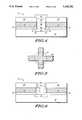
- FIG. 1Illustrated in FIG. 1 is a structure suitable for formation of a transistor 10.
- the transistor 10has a base layer which is a substrate 12 having a surface and having a first conductivity type. If transistor 10 represents a first transistor formed overlying a second transistor (not illustrated), the base layer for the first transistor is a conductive top layer or top electrode of the underlying second transistor.
- Substrate 12may be made of silicon, gallium arsenide, silicon on sapphire, epitaxial formations, germanium, germanium silicon, polysilicon, diamond, silicon on insulator (SOI), and/or like substrate materials.
- the substrate 12is made of silicon.
- a diffusion 14is formed within the substrate 12. Various methods may be used to form diffusion 14. These methods are discussed below.
- a first dielectric layer 16is formed overlying the substrate 12 and initially overlying the diffusion 14.
- a control electrode conductive layer 18is formed overlying the dielectric layer 16.
- conductive layer 18is polysilicon, but conductive layer 18 may be a metal, a salicide or silicide, germanium silicon, a polycide, or the like.
- a second dielectric layer 20is formed overlying the conductive layer 18.
- the dielectric layers 16 and 20, and all other dielectrics described hereinmay vary in physical and chemical composition based upon the function they perform.
- the dielectric layers described hereinmay be wet or dry silicon dioxide (SiO 2 ), nitride, silicon nitride, tetra-ethyl-ortho-silicate (TEOS) based oxides, boro-phosphate-silicate-glass (BPSG), phosphate-silicate-glass (PSG), boro-silicate-glass (BSG), oxide-nitride-oxide (ONO), tantalum pentoxide (Ta 2 O 5 ), plasma enhanced silicon nitride (P-SiN x ), titanium oxide, and/or the like. Specific dielectrics are noted where a specific dielectric is preferred or required.
- a masking layer of photoresist(not illustrated) is deposited overlying the dielectric layer 20.
- the masking layer(not illustrated) is conventionally patterned and etched to form a mask opening that exposes a portion of the dielectric layer 20.
- a portion of the dielectric layer 20is etched selective to the conductive layer 18 to form an opening in the dielectric layer 20.
- a portion of the conductive layer 18is etched selective to the dielectric layer 16 to deepen the opening by etching into the conductive layer 18.
- a portion of the dielectric layer 16is etched selective to the substrate 12 to further deepen the opening by etching into the dielectric layer 16. The etching of the dielectric layer 16 exposes diffusion 14.
- the etching of the dielectric layers 16 and 20 and control electrode conductive layer 18results in an opening that is self-aligned to the mask opening.
- the openingis referred to as a "device opening" in some cases.
- non-selective etch processingmay be used to form the device opening.
- the diffusion 14, in FIG. 1,is formed in one of at least two ways.
- diffusion 14can be implanted or diffused into the substrate selectively through the use of one of a photoresist mask, an oxide mask, a nitride mask or the like.
- Diffusion 14, in a similar mannercan be implanted through an oxide or like material to ensure a shallow, dopant-dispersed junction. This implantation or diffusion occurs before the formation of the conductive layer 18.
- the diffusion 14can be implanted or diffused after the formation of the device opening. The second method, when using implantation, is preferred due to the fact that the resulting diffusion 14 is self-aligned to the device opening or mask opening.
- the diffusion 14may be either N-type or P-type and may contain a plurality of dopant atoms (e.g. phosphorus and arsenic).
- the device openingmay be of any geometry or size but is preferably a circular contact or a rectangular contact of minimum lithographic size (on the order of 0.5 micron or less).
- FIG. 2illustrates a sidewall dielectric layer 22 formation step.
- a sidewall dielectric layer 22is formed on a sidewall of the conductive layer 18 that results from the formation of the opening. Due to the fact that the dielectric functions as a gate oxide, the dielectric layer 22 is in most cases a grown SiO 2 layer. The growth of dielectric layer 22 will result in a thin dielectric layer 24 being grown on the exposed surface of the diffusion 14.
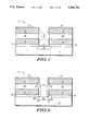
- FIG. 3illustrates a dielectric removal step for a portion of the dielectric layer 24.
- a cylindrical dielectric spacer 26 or like formationis formed overlying the dielectric layer 24 and adjacent the dielectric layer 22.
- the spacer 26is nitride or an oxide which can be etched selective to SiO 2 , cylindrical in geometry, and formed within and adjacent a sidewall of the device opening.
- the spacer 26forms an inner opening within the device opening.
- the spacer 26is used to protect the dielectric layer 22 from subsequent oxide etching.
- An oxide etchis then performed selective to spacer 26 and substrate 12. The oxide etch removes a portion of dielectric layer 24 that lies within the cylindrical dielectric spacer 26.
- a portion of the dielectric layer 24 which underlies the spacer and surround a periphery of the openingremains unetched.
- the spacer 26is then removed via conventional nitride or removable spacer techniques.
- first and second current electrodesalso respectively referred to as a drain and a source, and a channel region are formed.
- a grown conductive regionis used to form the first and second current electrodes and the channel region.
- the grown conductive regionis formed via epitaxial growth. Growth is initiated by heating transistor 10 and subjecting exposed portions of the diffusion 14 or the substrate 12 to a chemical compound such as dichloro-silane or a similar silicon source gas.
- Electrode 28is formed of a second conductivity type that is opposite the first conductivity type.
- in-situ dopingis preferred although ion implantation is possible. In-situ doping means that the drain electrode 28 is doped during growth by a dopant gas source. If the second conductivity type is P-type, then a boron-containing gas or a like dopant gas is used to dope drain electrode 28. If the second conductivity type is N-type, then a phosphorus-containing, arsenic-containing, or like dopant gas is used to dope electrode 28.
- Drain electrode 28is grown adjacent the first dielectric layer 16, with in-situ doping, until the drain electrode 28 is adjacent or nearly adjacent a bottom portion of the sidewall dielectric 22 as illustrated in FIG. 4.
- Lightly doped drain (LDD) regions or graded doping profilesmay be formed by altering the in-situ doping concentration.
- Epitaxial growthcontinues in a similar manner to form a channel region 30.
- the channel region 30is formed of the first conductivity type, preferably via in-situ doping as described herein. Due to the fact that dielectric layer 22 is a gate oxide and that conductive layer 18 functions as a gate, the doping in the channel region 30 can be used to adjust threshold voltages.
- the channel regionis grown, with in-situ doping, until the electrode is adjacent or nearly adjacent a top portion of the sidewall dielectric 22 as illustrated in FIG. 4.
- Epitaxial growthcontinues in a similar manner to form a second current electrode, also referred to as a source electrode, of a second conductivity type.
- the second current electrodehas two sub-regions. The two sub-regions are a lightly doped electrode 32 and a heavily doped electrode 34.
- the electrodes 32 and 34are formed by changing the in-situ doping concentration during growth. Initially, the second conductivity doping gas is at a predetermined concentration. After a predetermined time, and therefore after a predetermined epitaxial growth thickness, the lightly doped electrode 32 is formed and the dopant concentration is increased to a second predetermined level. While maintaining the second predetermined level, epitaxial growth continues to form the heavily doped electrode 34.
- LDD regionsresult in an increase in series resistance. If the LDD region is most needed, the advantages of the LDD configuration are preserved while reducing series resistance.
- a source and a drain regioncan be interchangeable in the structure of FIG. 4. If the source and drain functionality is switched (i.e. the source is formed underlying the channel region 30 and the drain is formed overlying the channel region 30), an LDD structure may be formed for the lower electrode 28. It should also be apparent that a full LDD transistor can be formed by forming LDD regions for both the source and the drain. It is important to note that LDD regions are optional and that the doping for both the source and the drain regions can be a constant.
- a thin film transistorcan be formed by the epitaxial approach described above. If the substrate 12 is polysilicon instead of single crystalline silicon, then polysilicon electrode regions and channel regions are epitaxially grown. This growth forms a vertical TFT that will be similar in structure to the transistor 10 of FIG. 4. A vertical TFT can be helpful in terms of saving area in memory cell designs.
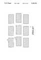
- FIG. 1can be used to form a multi-gated transistor having a plurality of gate electrodes.
- the plurality of gate electrodes or N gates, where N is an integer,is formed in one of two ways.
- a first methodinvolves forming a gate conductive layer, lithographically masking the gate conductive layer, and etching to form N physically separate and distinct gates. In this method, photolithographic alignment to the device opening is critical and therefore this method is not preferred.
- a preferred methodwould be to form a gate conductive layer as a single region or layer and use the formation of the device opening to separate the single gate conductive layer into N conductive gate regions. This method assures that all of the gates are self-aligned to the device opening.
- FIG. 5illustrates, in one form, a top perspective view of the gate conductive layer 18 and a device opening 21 that is used to etch the layer 18 into N self-aligned gates, where N is four in the illustrated example.
- FIG. 4illustrates an alternative method that may be used to replace the steps of FIGS. 2-3 and achieve a greater epitaxial seeding area.
- a dielectric layer 20 etch followed by a conductive layer 18 etch, followed by a dielectric layer 16 etchis usually used to expose the substrate 12 and self-align various features of transistor 10.
- a dielectric layer 22'can be formed as illustrated in FIG. 6.
- the formation of the dielectric layer 22'forms a surface dielectric layer (not illustrated) overlying the diffusion 14 which may be removed. The difference is that a spacer is no longer needed.
- a reactive ion etch (RIE)can be performed to completely remove the surface dielectric layer from the surface of the diffusion 14 without affecting the recessed dielectric layer 22'.
- an optional dielectric spacer 22"may be formed laterally adjacent the opening and laterally adjacent the conductive layer 18 as illustrated in FIG. 6.
- the optional dielectric spacer 22"is preferably formed of a TOES-based oxide.
- the spaceris then RIE etched to form the dielectric layer 22' as a composite dielectric having a polysilicon grown SiO 2 layer adjacent the conductive layer 18 and a TOES-based oxide layer adjacent the polysilicon grown SiO 2 layer. This composite oxide formation is used to misalign micropores (i.e. defects) within dielectric layer 22' to create an improved gate dielectric layer.
- the dielectric layer 22'is usually nitrided via N 2 , N 2 O, NH 3 , or an equivalent.
- a nitrided oxide materialresists plasma damage more than other oxide materials.
- a nitrided oxideis advantageous but optional for transistor 10.
- Both N-channel and P-channel transistorscan be formed. If the first conductivity is N-type and the second conductivity is P-type, then a P-channel vertical transistor is formed. If the first conductivity is P-type and the second conductivity is N-type then an N-channel vertical transistor is formed.
- the transistor 10 of FIG. 1will have a conductive layer 18 that completely surrounds the channel region 30.
- a completely surrounding conductive layer 18allows for maximum current carrying capability, a more consistent aspect ratio (transistor width/transistor length ratio), and reliable photolithographic alignment.
- an increased packing densitycan be achieved by partially surrounding the channel region 30 with conductive layer 18. This increased packing density is achieved by avoiding spacing requirements between conductors for most polysilicon and metal design rules.
- the transistor 10may be used to form vertically stacked vertical transistors. These vertically stacked vertical transistors may then be used to form compact static random access memory (SRAM) cells. All of the transistors which are used to manufacture the compact SRAM cells may have all of the flexibility described above for transistor 10 with respect to sidewall dielectric formation, LDD regions, doping profiles, diffusions, oxides, and the like. Other vertical transistors exist and may be used in the embodiments presented herein.
- Transistor 10may be vertically stacked on top of another transistor 10 to implement memory cells having surface area of approximately one square micron. For example, if a lithographic feature size of 0.25 micron is used and a minimum spacing requirement between features is on the order of 0.25 micron, then a one square micron cell can be achieved. If a feature size of 0.4 micron is used and a minimum spacing requirement between features is on the order of 0.4 micron, then roughly a 2.5 square micron cell can be achieved. The contact opening or device opening is usually sub-micron in size. If a feature size of 0.5 micron is used and a minimum spacing requirement between features is on the order of 0.5 micron, then roughly a four square micron cell can be achieved. FIGS.
- a plurality of M vertical transistorswherein M is an integer equal to two, is stacked overlying each other.
- Each of the stacked transistorsis independently either N-channel or P-channel devices.
- P-channelmeans that a transistor has P-type doped source and drain regions.
- N-channelmeans that a transistor has N-type doped source and drain regions.
- Each of the stacked transistorshas from one to N conductive gates and N may differ in value between each of the M stacked transistors.
- the second current electrode, or top electrode, of a bottom transistoris connected to a first current electrode, or bottom electrode, of an overlying transistor. Due to this connection scheme, a P-type region will be in contact with an N-type region in some cases and create a PN junction. To avoid diode voltage drops across PN junctions, a salicide, metal, silicide, or like material is used to electrically short circuit the PN junction.
- FIGS. 7-14elements that are analogous to elements of FIGS. 1-5 are identically labeled for brevity and therefore not explained in detail below.
- the elements of FIGS. 7-14 that are analogous to elements in FIGS. 1-5should be allowed all of the alternatives and modifications described herein for FIGS. 1-5.
- FIG. 7is substantially equivalent to FIGS. 1-2 and illustrates formation of dielectric layers 16, 20, and 27, formation of conductive layers 18, 19, and 25, formation of the device opening that exposes the substrate 12, formation of sidewall dielectric 22 and dielectric layer 24, and formation of the diffusion 14.
- Conductive layers 18 and 19are formed from a single conductive layer in a manner similar to that illustrated in FIG. 5.
- Conductive layer 25has been formed overlying the dielectric layer 20 and functions as an output conductor.
- a dielectric layer 27is formed overlying the conductive layer 25.
- the conductive layers 18 and 19respectively form a first conductive gate electrode and a second conductive gate electrode. Therefore, a transistor formed within the device opening and adjacent the conductive layers 18 and 19 will be double-gated. It is important to note that conductive layers 18 and 19 may be formed collectively as a single gate in FIG. 7.
- FIG. 8the sidewall dielectric method that utilizes a spacer 26 for protection, which was described above, is illustrated. It is important to note that the recessed sidewall approach presented herein in FIG. 6 is a viable alternative to the spacer method in FIG. 8 and vice versa. A portion of dielectric layer 25 is removed in FIG. 8.
- a conductive regionis formed within the device opening having electrode regions and a channel region nearly identical to FIG. 4.
- a half LDD structureis illustrated.
- the method of forming electrodes and channel regions via epitaxial growthis described in detail in connection with FIG. 4.
- the conductive region that forms the electrodes and channel regionmay be optionally formed in a full LDD structure, a half LDD structure, or in a structure with no LDD regions.
- the conductive region and the conductive layers 18 and 19form a first transistor.
- portions of the dielectric layer 27are removed to expose portions of the conductive layer 25.
- a brief epitaxial growth step or a deposition and etch procedureis used to form an electrical contact between conductive layer 25 and heavily doped electrode 34.
- a brief epitaxial growth steplinks conductive layer 25 to the heavily doped region 34 via the epitaxial link layer 36.
- Sidewall contacts, other forms of epitaxial growth, deposition and etch procedures, and the likecan be used to form a link layer similar to layer 36.
- dielectric layers 38 and 42 and a conductive layer 40are formed to allow for a formation of a second transistor.
- the second transistoroverlies the first transistor which is gated by conductive layers 18 and 19.
- the second transistoruses heavily doped electrode 34 as a base layer.
- the base layerprovides epitaxial quality material for the formation of the overlying second transistor.
- the dielectric layers 38 and 42 and the conductive layer 40are formed in a manner similar to that described in FIG. 1.
- a second device openingis formed through the dielectric layers 38 and 42 and the conductive layer 40.
- a sidewall dielectric 44is formed in a manner similar to that described in connection with FIGS. 1-2.
- the second transistoris single-gated by the conductor 40.
- Conductor 40either completely surrounds a perimeter of the second opening or partially surrounds the perimeter of the second opening.
- a dielectric layer 46analogous to dielectric layer 24 of FIG. 7, is formed overlying the heavily doped electrode 34 during sidewall dielectric layer 44 formation.
- FIG. 13illustrates a sidewall spacer and dielectric removal step analogous to that of FIG. 8.
- the dielectric layer 46 that is not underlying the spaceris removed.
- a second conductive regionis formed having a first current electrode 50, a channel region 52 and a second current electrode which has sub-regions referred to as a lightly doped drain region 54 and a highly doped drain region 56.
- a plurality of structures similar to the structure illustrated in FIG. 14may be connected as taught below to form compact SRAM cells.
- FIGS. 15-20illustrate another method for forming a vertically stacked vertical transistor structure in accordance with the present invention.
- FIGS. 7-14illustrate a technique wherein stacked transistors are formed one transistor at a time and with no self-alignment.
- FIGS. 15-20illustrate a method wherein a plurality of transistors is formed in a stack, the transistors being self-aligned to each other.
- Vertical SRAM cells described hereinmay use either the self-aligned or the non-self-aligned method.
- Conductive layers 60, 64, and 68 and dielectric layer 58, 62, 66, and 70are formed overlying the substrate 12 as illustrated.
- the dielectric layers 58, 62, 66, and 70are illustrated as being planar. Planarization is illustrated but is not required for a functional stacked device. Planarization will improve topography and reduce topographical problems in overlying conductive layers, such as metal layers. If a planarization method is not used, a "volcano-shaped" stacked logic device results.
- a device opening or openingis formed.
- the openinghas sidewalls and is formed by etching portions of the conductive layers 60, 64, and 68 and dielectric layers 58, 62, 66, and 70.
- the conductive layers 60, 64, and 68are over-etched to laterally recess the sidewalls of the opening adjacent to the conductive layers 60, 64, and 68 as described in FIG. 6.
- This recessingallows laterally recessed sidewall dielectric layers 72 to be formed concurrently with the formation of a dielectric layer 74. Due to the fact that the dielectric layers 72 are recessed, dielectric layer 74 is etched without affecting the dielectric layers 72 as described herein.
- the diffusion 14, in one form,is formed in the substrate 12 before or during formation of the conductive layers 60, 64, and 68 and dielectric layers 58, 62, 66, and 70 as illustrated in FIG. 15.
- the diffusion 14is formed self-aligned to the opening as in FIG. 16.
- all transistors that are stacked on top of one anotherare self-aligned to each other. Therefore, FIG. 16 illustrates a fully self-aligned process which may be used to form SRAM cells.
- FIG. 17illustrates the use of full LDD transistors.
- the first transistorhas a first current electrode which has a lightly doped region 76 and a heavily doped region 74.
- the first transistorhas a channel region 78.
- the first transistorhas a second current electrode which has a lightly doped region 80 and a heavily doped region 82.
- a second transistorhas a first current electrode which has a lightly doped region 86 and a heavily doped region 84.
- the second transistorhas a channel region 88.
- the second transistorhas a second current electrode which has a lightly doped region 90 and a heavily doped region 92.
- a dielectric layer 94protects the heavily doped region 92 from subsequent etch processing and damage. Together, a heavily doped region and a lightly doped region form a single current electrode.
- FIG. 18illustrates a method that can be used for saliciding a PN junction when a fully self-aligned process, such as the process illustrated in FIG. 15, is used.
- An etch hole 96is formed that exposes the conductive layer 64.
- An etch stepis used to remove a portion of the conductive layer 64 as illustrated in FIG. 18.
- a short dielectric etchis used to remove the sidewall dielectric 72 exposed by the conductive layer 64 etch.
- a masking layer 95which is preferably photoresist is used to protect the dielectric layer 94. The removal of the exposed sidewall dielectric 72 exposes a portion of the heavily doped regions 82 and 84.
- conformal CVD titanium or a like materialis deposited and a salicide anneal step is performed to form a salicided region 97.
- An effective electrical short circuitis now bridging across the PN junction formed by the heavily doped regions 82 and 84.
- conductive regions 99 and 98are formed to make electrical contact to the inverter gate 13.
- Region 98forms an output contact of the inverter gate 13 and region 99 forms a power supply connection.
- dielectric layer 94is removed.
- this salicide formation step in FIGS. 18-19is difficult because it is performed in a process that has self-aligned stacked transistors.
- the process of FIGS. 7-14is more suitable for a salicide formation step due to the fact that one suitable for a salicide formation step due to the fact that one transistor is formed at a time.
- a conventional deposition, etch, and anneal cyclecan form a salicide region on a first transistor's heavily doped region before the second transistor's heavily doped region is formed, thereby electrically short circuiting the resulting PN junction.
- the only disadvantage with this approachis that the resulting salicide region could impede epitaxial growth of conductive regions if formed over a large surface area of the heavily doped regions. Deciding one method over the other is design choice and depends upon an application of the device, available equipment, and equipment capabilities.
- an SRAM cell or a plurality of SRAM cellsmay be manufactured as taught below.
- FIG. 21the structure of FIG. 20 is illustrated in a top perspective view. Only conductive layers 60, 64, and 68 are illustrated along with the opening which is illustrated in FIG. 21 as opening 73.
- FIG. 22illustrates in a schematic diagram a conventional SRAM cell.
- FIG. 22illustrates N-type latch transistors 100 and 102, N-type pass transistors 104 and 106, and resistive devices 108 and 110.
- An interconnection 118connects the transistors 104 and 100 to the gate of transistor 102.
- An interconnection 120connects the transistors 102 and 106 to the gate of transistor 100.
- the resistive devices 108 and 110may be resistor elements, diodes, thin film transistors (TFTs), P-type transistors, or the like. If resistive devices 108 and 110 are transistor devices, then interconnection 118 connects to a gate of resistive device 110 and interconnection 120 connects to a gate of resistive device 108.
- Power supply (Vdd) and ground connectionsare illustrated in FIG. 22.
- Bit lines 114 and 116 and a word line 112are illustrated.
- FIG. 22also illustrates transistor nodes 101 and 103.
- FIG. 23illustrated in top perspective view a layout which may be used to form an SRAM cell in accordance with the present invention.
- a vertical transistor stack 124contains two transistors and is one lithographic feature in dimension.
- the vertical transistor stack 124is formed using the techniques taught in FIGS. 1-21 and contains two stacked vertical transistors (similar to FIG. 14 or FIG. 20).
- the two stacked transistorsare analogous to the transistors 102 and 106 of FIG. 22.
- Transistor 102is formed underlying transistor 106 in this embodiment.
- a vertical transistor stack 122contains two transistors and is one lithographic feature in dimension.
- the vertical transistor stack 122is formed using the techniques taught in FIGS. 1-21 and contains two stacked vertical transistors (similar to FIG. 14 or FIG. 20).
- the two stacked transistorsare analogous to the transistors 100 and 104 of FIG. 22.
- Transistor 100is formed underlying transistor 104 in this embodiment.
- the interconnect 118connects the transistor node 101 (see FIG. 22) which lies between transistors 100 and 104 within vertical transistor stack 122 to the gate of transistor 102 located within the vertical transistor stack 124.
- interconnect 118is preferably made of polysilicon or a like conductor or semiconductor.
- the interconnect 120connects the transistor node 103 (see FIG. 22) which lies between transistors 102 and 106 within vertical transistor stack 124 to the gate of transistor 100 located within the vertical transistor stack 122.
- interconnect 120is preferably made of polysilicon or a like conductor or semiconductor. Interconnects 118 and 120 are respectively connected between the vertical transistor stacks 122 and 124 via vertical stacks 126 and 128.
- Interconnects 118 and 120are analogous to connecting conductive layer 25 of a first transistor stack formed in accordance with FIG. 14 to conductive layer 18 of a second transistor stack also formed in accordance with FIG. 14. Interconnects 118 and 120 are illustrated in subsequent cross-sectional diagrams (FIGS. 24-26).
- Word lines 112are illustrated in FIG. 23.
- Word lines 112are, for example, each analogous to conductive layer 60 of FIG. 20.
- a diffusion(not illustrated) carries a ground potential along line 24--24 of FIG. 23 and connects to the bottom of each of the vertical transistor stacks 122 and 124.
- This diffusion(not illustrated) may be a straight diagonally-directed diffusion or may be zig-zagged in geometric structure.
- the diffusions illustrated hereinmay be salicided or silicided.
- An ion implant stepwhich implants a refractory metal material such as cobalt into the diffusion, may be used to form a buried silicide or salicide layer within the diffusion. Other silicide/salicide methods and materials exist. Silicides and/or salicides form diffusions with a greater conductivity.
- the vertical stack 126contains either a resistor device or a TFT device analogous to resistive device 108 of FIG. 22.
- the vertical stack 126contains either a resistor device or a TFT device analogous to resistive device 110 of FIG. 22.
- These TFT or resistive devicesare connected to a power supply conductor (not illustrated in FIG. 23) at a top portion of the vertical stacks 126 and 128. These connections are illustrated in more detail in FIGS. 24-26.
- FIG. 24illustrated FIG. 23 cross-sectioned along the line 24--24.
- FIG. 24illustrates the vertical transistor stacks 122 and 124 of FIG. 23.
- the vertical transistor stack 122holds the transistor 100 of FIG. 22 and the transistor 104 of FIG. 22 as illustrated.
- the vertical transistor stackis analogous to the structure taught in FIG. 14 or FIG. 20 and therefore analogous elements of FIG. 24 are labeled identical to FIG. 14.
- the diffusion 14carries a ground (Vss) signal.
- the vertical transistor stack 124is similar to the vertical transistor stack 122 and FIGS. 14 and 20 in structure and is therefore not specifically labeled.
- the vertical transistor stack 124is used to form transistors 102 and 106 of FIG. 22.
- Conductive layer 40 of FIG. 24forms the word line 112 illustrated in FIG. 22.
- the interconnection 118 and 120 of FIG. 22are illustrated in FIG. 24 as first and second polysilicon layers.
- Interconnection 120connects the transistors 102 and 106 to the gate of transistor 100 via a connection within the vertical stack 128.
- Interconnection 118connects the transistors 100 and 104 to the gate of transistor 102 via a connection within the vertical stack 126.
- the vertical transistor stacks 124 and 122may be formed simultaneously. All four transistors 100, 102, 104, and 106 are N-type and therefore require no silicide electrical short circuit regions as taught in FIG. 20.
- FIG. 25illustrates FIG. 23 cross-sectioned along a line 25--25.
- the vertical transistor stack 122 of FIG. 23is illustrated and the vertical stack 128 of FIG. 23 is illustrated.
- the vertical transistor stack 122 of FIG. 25is the same vertical transistor stack 122 illustrated in FIG. 24. The only difference is that the vertical transistor stack 122 of FIG. 25 is cross-sectioned from a different direction (line 25--25 instead of line 24--24).
- the vertical stack 128is illustrated.
- the interconnect 120connects the gate of transistor 100 to the transistors 102 and 106 (the output node 103 of FIG. 22).
- a portion of the vertical stack 128is used to vertically strap two conductive layers to form interconnect 120 as illustrated in FIG. 25.
- a top portion of the vertical stack 128is used to form a resistive device 134 analogous to resistive device 110 of FIG. 22.
- the resistive deviceis a polysilicon resistor element or a resistor element formed from a resistive material.
- the resistor elementmay be doped, compensated, or undoped.
- a conductive layer 136which is preferably a metal material, connects the resistive device 134 to a power supply voltage (Vdd).
- the resistive device 134may be formed by plug and planarization/etch-back processing, epitaxial growth, or the like. In another form, the resistive device 134 may be formed as a thin film transistor (TFT) or a vertical polysilicon transistor by the process illustrated in FIGS. 1-6.
- TFTthin film transistor
- FIGS. 1-6the process illustrated in FIGS. 1-6.
- FIG. 26illustrates FIG. 23 cross-sectioned along a line 26--26.
- the vertical transistor stack 122 of FIG. 23is illustrated and the vertical stack 126 of FIG. 23 is illustrated.
- the vertical transistor stack 122 of FIG. 26is the same vertical transistor stack 122 illustrated in FIG. 24. The only difference is that the vertical transistor stack 122 of FIG. 26 is cross-sectioned from a different direction (line 26--26 instead of line 24--24).
- the vertical stack 126is illustrated.
- the interconnect 118connects the gate of transistor 102 to the transistors 100 and 104 (the output node 101 of FIG. 22).
- a portion of the vertical stack 126is used to vertically strap two conductive layers to form interconnect 118 as illustrated in FIG. 26.
- a top portion of the vertical stack 126is used to form a resistive device 138 analogous to resistive device 108 of FIG. 22.
- the resistive deviceis a polysilicon resistor element or a resistor element formed from a resistive material.
- the resistor elementmay be doped, compensated, or undoped.
- a conductive layer 136which is preferably a metal material, connects the resistive device 138 to a power supply voltage (Vdd).
- the resistive device 138may be formed by plug and planarization/etch-back processing, epitaxial growth, or the like. In another form, the resistive device 138 may be formed as a thin film transistor (TFT) or a vertical polysilicon transistor by the process illustrated in FIGS. 1-6.
- TFTthin film transistor
- FIGS. 1-6the process illustrated in FIGS. 1-6.
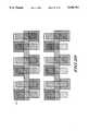
- FIGS. 27-33a top down process flow of SRAM device-critical layers is illustrated in FIGS. 27-33 to further describe the method of manufacturing the SRAM of FIGS. 23-26.
- FIG. 22illustrates a first layout and the FIGS. 27-33 illustrate a second layout. Some of the dielectric layers, substrate layers, diffusions, and like layers are not illustrated in FIGS. 23-26. Only conductive layers are illustrated in FIGS. 27-33 for clarity, and only one SRAM cell is completely labeled.
- a substrate 12is provided. Diffusions (not illustrated) are formed within the substrate 12 to carry ground potentials, other potentials, or logic signals as required. The diffusions (not illustrated) are optionally salicided or silicided as taught herein.
- a first dielectric layer(not illustrated) is formed corresponding to dielectric layer 16 of FIG. 24. Polysilicon, polycide, or a like layer is formed and patterned to create first conductive layer. The first conductive layer forms portions of the interconnections 118 and 120 as illustrated. Doping of the first conductive layer is performed by in-situ doping, diffusion, ion implantation, or the like.
- a second dielectric layer(not illustrated) is formed corresponding to the dielectric layer 20 of FIG. 24. Planarization of the dielectric layers described herein is optional.
- a second conductive layerwhich is preferably polysilicon, amorphous silicon, polycide, or a like material, is formed and patterned over the second dielectric layer (not illustrated). The second dielectric layer is used to form another portion of the interconnects 118 and 120 as illustrated. Doping of the second conductive layer is performed by in-situ doping, diffusion, ion implantation, or the like.
- a third dielectric layer(not illustrated) is formed corresponding to the dielectric layer 38 of FIG. 24. Planarization of the third dielectric layer (not illustrated) is optional.
- a third conductive layerwhich is preferably polysilicon, amorphous silicon, polycide, or a like material, is formed and patterned over the second dielectric layer (not illustrated). The third dielectric layer is used to form the word lines of the SRAM cell which are analogous to the conductive layer 40 of FIG. 24. Doping of the third conductive layer is performed by in-situ doping, diffusion, ion implantation, or the like.
- contact holesare formed and the vertical transistor stacks 122 and 124 are formed as taught herein. All four of the transistors (transistors 100, 102, 104, and 106) formed within the vertical transistor stacks 122 and 124 are vertical N-type transistors. Epitaxial growth, as taught herein, is preferred for the formation of the four transistors.
- the vertical transistor stacks 122 and 124may be formed sequentially or simultaneously.
- contact holesare formed and the vertical stacks 126 and 128 are formed as taught herein.
- the vertical stacks 126 and 128complete the electrical connection of the interconnects 118 and 120.
- a top portion of the vertical stacks 126 and 128are used to form resistive devices analogous to resistive devices 134 and 138 of FIGS. 25 and 26.
- the vertical stacks 126 and 128may be formed sequentially or simultaneously.
- a conventional inter-level dielectric(not labeled) is formed and a conductive layer 136 is formed to connect a top portion of the vertical stacks 126 and 128 to a power supply potential (Vdd).
- the conductive layer 136is preferably a metal layer.
- a second conventional inter-level dielectric(not labeled) is formed and a conductive layer 131 and a conductive layer 133 is formed to connect a top portion of the vertical transistor stacks 122 and 124.
- the conductive layers 131 and 133form a pair of bit lines for the SRAM cell.
- the conductive layers 131 and 133are formed in a single metal layer and carry complementary logic signals.
- inventive methods and devices presented herein for SRAM formationprovide vertical transistor logic and vertical circuits that have reduced surface area, improved short channel behavior, and reduced channel length variation. Leakage currents are reduced due to the fact that current electrodes and channel regions are isolated from the substrate.
- a length of the transistor 10is controlled by a conductive layer 18 deposition thickness L as illustrated in FIG. 1. Therefore, the inventive transistor has gate and channel lengths that are independent of lithography, smaller than lithography allows, and controlled within a smaller variation.
- deposition thickness L, and not increased substrate surface areamay be used to adjust P-channel device aspect ratios and device characteristics to match N-channel device characteristics.
- the device width of the transistors used to form the inventive memory device taught hereinis larger than conventional planar transistors of the same surface area due to the fact that the channel width of a cylindrical transistor is the cylinder's circumference.
- the contact holes taught hereinnot required to be spherical, and may be triangular, rectangular, oval, a square, or other geometries. Due to the smaller channel length and the greater channel width, a current carrying capability of the transistor logic increases without increasing logic circuit surface area. In almost all cases, SRAM cell substrate surface area will be between 3 square microns and sub-one square micron for the SRAM cell technology taught herein.
- the inventive memory deviceis formed within a contact hole which is lithographically the smallest feature size in an integrated circuit.
- the formation of the inventive SRAM cellmay require only a few photolithography steps if the SRAM is formed entirely self-aligned as in FIGS. 15-16.
- One maskis all that is needed for transistor source electrode, drain electrode, and channel region formation even if the transistors are formed sequentially one at a time.
- Many features of the transistors taught herein, such as diffusions and gates,can be self-aligned.
- Asymmetric source and drain electrodesresult and LDD and half LDD transistors are easily formed. Bulk inversion of the channel region can be achieved for sub-micron channel region dimensions. Low logic off current, known cross-talk phenomenon, and current leakage to the substrate is minimized due to the fact that many diffusions are placed in series and isolated from the substrate.
- the inventive SRAM cellhas transistors which are placed physically closer to each other than conventional SRAM cell transistors, the inventive SRAM cell will avoid many polysilicon, silicon, and metal junctions, and may have increased speed of operation.
- the inventive SRAMmay be formed having transistors in an opening that is too large to fully deplete.
- Fully depleted transistors and bulk inverted transistorare advantageous and possible for the transistor taught herein if small lithographic geometries are achieved.
- Full channel region depletion or bulk channel inversionis also desirable for large geometry transistors in order to achieve improved performance. If a sidewall contact is made to the inventive transistor channel region and the sidewall contact is connected to the substrate or a power supply, depending on device conductivity type, improved depletion can be achieved.
- the sidewall contactis possible for logic gates that have transistor channel regions with non-gated sidewall portions or partially surrounded channel regions. Due to the partially surrounding gate structure presented herein, a channel contact may be made and depletion will be improved.
- interconnects 118 and 120are output nodes for the SRAM cell (i.e. analogous to or coupled to the output nodes 101 and 103 if FIG. 22). It is known in the art that a biased capacitor placed adjacent the output nodes of an SRAM improves a known and understood soft error immunity. Therefore, a diffusion (not illustrated) may be formed underneath the interconnects 118 and 120 in FIGS. 25 and 26. This diffusion (not illustrated) may be connected to the diffusion 14 and therefore connected to ground in a preferred form, or may be connected to another conventional potential. The diffusion (not illustrated) will add capacitive coupling to the interconnects 118 and 120 and improve soft error immunity.
- the SRAM memory taught hereinmay be inverted wherein the Vdd supply voltage is a diffusion region and Vss supply voltage is formed in metal.
- P-channel and N-channel transistorsmay be stacked on top of one another to form other SRAM embodiments.
- Polysilicon vertical TFTsmay be used as resistive devices.
- Other vertical transistorsexist in the prior art and any vertical transistor may be used to form an SRAM cell which is similar to the SRAM cell taught herein.
- Various techniques for sidewall dielectric formationexist and various spacer techniques can be used in conjunction with the present invention.
- Various methods of silicidationexist. Many of the features of the inventive device can be optionally self-aligned or not self-aligned.
- Nitrided gate oxidesare used to reduce RIE (reactive ion etch) damage to sidewall gate dielectrics.
- RIEreactive ion etch
- Various process integration schemesare possible due to the wide range of layouts and process flows.
- Other vertical layoutsexist. It should be apparent that the methods and devices taught herein can be used to form other conventional SRAM-like memory cells. In some cases, the resistive devices presented herein may not need to be large.
- the vertical transistors in the inventive SRAM cellhave current electrodes which are isolated from the substrate. This isolation allows the electrodes to function as capacitors.
- the inventive cellmay operate as a cross between a dynamic random access memory (DRAM) and an SRAM cell.
- DRAMdynamic random access memory
- other SRAM circuitsmay be made by using the methods and devices taught herein.
- an N channel transistormay be formed underlying a P-channel TFT or an N-channel transistor may be formed underlying a resistor.
Landscapes
- Thin Film Transistor (AREA)
- Metal-Oxide And Bipolar Metal-Oxide Semiconductor Integrated Circuits (AREA)
- Semiconductor Memories (AREA)
Abstract
Description
This is a continuation-in-part of application Ser. No. 07/844,088, filed Mar. 02, 1992 now abandoned.
The present invention relates generally to semiconductor device and process technology, and more particularly, to semiconductor memories.
Planar transistors are often used to fabricate integrated circuit memory devices such as static random access memories (SRAM). A planar transistor has a diffused source electrode and drain electrode separated by a channel region. Overlying the channel region is a gate electrode that is separated from the channel region by a gate oxide. Planar transistors, although used and useful in many integrated circuit memory applications, are area intensive and consume a large amount of substrate area per transistor. In addition, with integrated circuit geometries decreasing into sub-micro ranges, planar transistors have various disadvantages. At smaller geometries and thinner gate oxide thicknesses, well documented problems such as hot carrier injection, leakage currents, isolation, short channel behavior, and channel length variations are major problems in planar transistors.
To overcome some of the disadvantages described above for planar transistors, thin film transistors (TFTs), elevated source and drain transistors, lightly doped drain (LDD) transistors, and other improvements were developed. Although the improvements reduced some of the disadvantages listed above, the improvements had some undesirable characteristics. The primary undesirable characteristic is the fact that the improved transistors were, in most cases, as area intensive or more area intensive than the planar transistor or, in the case of the TFT, did not perform as well as planar transistors. For example, small memory cell areas can result via the use of TFTs, but TFTs are highly resistive and therefore not adequate for all applications.
Various approaches have been used to try to reduce circuit surface area and increase transistor packing density while at the same time reducing some of the adverse effects described above. The surrounding gate transistor (SGT) was developed wherein a spacer gate and planar diffusions are used to form a transistor. The SGT reduced some of the disadvantages that affect planar transistors and reduced surface area due to a vertically positioned spacer gate. Topography problems and the geometry of the SGT usually result in source, gate, and drain contacts that are difficult to achieve and are difficult to consistently produce using submicron technology. In addition, doping of source regions, drain regions, and channel regions via implants can be difficult due to geometry and may require special processing.
Conventional planar transistors and TFT technology are not currently progressing at a rate which will allow for the formation of large memory cells, such as 64 Mbit SRAMs or 256 Mbit SRAMs.
The previously mentioned disadvantages are overcome and other advantages achieved with the present invention. The present invention comprises a memory device. The memory device has a substrate which has a surface. A first vertical structure is formed at least partially overlying the surface of the substrate. The first vertical structure has a first vertical transistor underlying a second semiconductor device. A second vertical structure is formed at least partially overlying the surface of the substrate and laterally adjacent the first vertical structure. The second vertical structure has a second vertical transistor underlying a second semiconductor device. Electrical interconnects are coupled to the first and second vertical transistors and the first and second semiconductor devices to form said memory device.
The present invention will be more clearly understood from the detailed description below in conjunction with the accompanying drawings.
FIGS. 1-4 illustrate, in cross-sectional form, a transistor for use in a semiconductor memory device and method of formation in accordance with the present invention;
FIG. 5 illustrates, in a top perspective form, a vertical transistor having a plurality of gates for use in a semiconductor memory device in accordance with the present invention;
FIG. 6 illustrates, in cross-sectional form, an alternative method of sidewall dielectric formation for a transistor for use in a semiconductor memory device in accordance with the present invention;
FIGS. 7-14 illustrate, in cross-sectional form, a pair of vertically stacked vertical transistors and method of formation in accordance with the present invention;
FIGS. 15-20 illustrate, in cross-sectional form, another pair of vertically stacked vertical transistors and another method of formation in accordance with the present invention;
FIG. 21 illustrates, in top perspective view, one top perspective embodiment of the pair of vertically stacked vertical transistors of FIG. 20;
FIG. 22 illustrates, in schematic form, a conventional static random access memory (SRAM);
FIG. 23 illustrates, in top perspective view, a static random access memory (SRAM) in accordance with the present invention;
FIG. 24 illustrates, in cross-sectional form, the static random access memory of FIG. 23 cross-sectioned alongline 24--24;
FIG. 25 illustrates, in cross-sectional form, the static random access memory of FIG. 23 cross-sectioned alongline 25--25;
FIG. 26 illustrates, in cross-sectional form, the static random access memory of FIG. 23 cross-sectioned alongline 26--26;
FIGS. 27-33 illustrates, in top perspective view, a method for making another static random access memory (SRAM) in accordance with the present invention.
Illustrated in FIG. 1 is a structure suitable for formation of atransistor 10. Thetransistor 10 has a base layer which is asubstrate 12 having a surface and having a first conductivity type. Iftransistor 10 represents a first transistor formed overlying a second transistor (not illustrated), the base layer for the first transistor is a conductive top layer or top electrode of the underlying second transistor.Substrate 12 may be made of silicon, gallium arsenide, silicon on sapphire, epitaxial formations, germanium, germanium silicon, polysilicon, diamond, silicon on insulator (SOI), and/or like substrate materials. Preferably, thesubstrate 12 is made of silicon. Adiffusion 14 is formed within thesubstrate 12. Various methods may be used to formdiffusion 14. These methods are discussed below. A firstdielectric layer 16 is formed overlying thesubstrate 12 and initially overlying thediffusion 14. A control electrodeconductive layer 18 is formed overlying thedielectric layer 16. In a preferred form,conductive layer 18 is polysilicon, butconductive layer 18 may be a metal, a salicide or silicide, germanium silicon, a polycide, or the like. A seconddielectric layer 20 is formed overlying theconductive layer 18.
Thedielectric layers
In FIG. 1, a masking layer of photoresist (not illustrated) is deposited overlying thedielectric layer 20. The masking layer (not illustrated) is conventionally patterned and etched to form a mask opening that exposes a portion of thedielectric layer 20. A portion of thedielectric layer 20 is etched selective to theconductive layer 18 to form an opening in thedielectric layer 20. A portion of theconductive layer 18 is etched selective to thedielectric layer 16 to deepen the opening by etching into theconductive layer 18. A portion of thedielectric layer 16 is etched selective to thesubstrate 12 to further deepen the opening by etching into thedielectric layer 16. The etching of thedielectric layer 16 exposesdiffusion 14. The etching of thedielectric layers conductive layer 18 results in an opening that is self-aligned to the mask opening. The opening is referred to as a "device opening" in some cases. In another form, non-selective etch processing may be used to form the device opening.
Thediffusion 14, in FIG. 1, is formed in one of at least two ways. In one form,diffusion 14 can be implanted or diffused into the substrate selectively through the use of one of a photoresist mask, an oxide mask, a nitride mask or the like.Diffusion 14, in a similar manner, can be implanted through an oxide or like material to ensure a shallow, dopant-dispersed junction. This implantation or diffusion occurs before the formation of theconductive layer 18. In a second method, thediffusion 14 can be implanted or diffused after the formation of the device opening. The second method, when using implantation, is preferred due to the fact that the resultingdiffusion 14 is self-aligned to the device opening or mask opening. Thediffusion 14 may be either N-type or P-type and may contain a plurality of dopant atoms (e.g. phosphorus and arsenic). The device opening may be of any geometry or size but is preferably a circular contact or a rectangular contact of minimum lithographic size (on the order of 0.5 micron or less).
FIG. 2 illustrates asidewall dielectric layer 22 formation step. Asidewall dielectric layer 22 is formed on a sidewall of theconductive layer 18 that results from the formation of the opening. Due to the fact that the dielectric functions as a gate oxide, thedielectric layer 22 is in most cases a grown SiO2 layer. The growth ofdielectric layer 22 will result in athin dielectric layer 24 being grown on the exposed surface of thediffusion 14.
The formation of thedielectric layer 24 is a side-effect that is undesirable. Therefore, FIG. 3 illustrates a dielectric removal step for a portion of thedielectric layer 24. Acylindrical dielectric spacer 26 or like formation is formed overlying thedielectric layer 24 and adjacent thedielectric layer 22. Preferably thespacer 26 is nitride or an oxide which can be etched selective to SiO2, cylindrical in geometry, and formed within and adjacent a sidewall of the device opening. Thespacer 26 forms an inner opening within the device opening. Thespacer 26 is used to protect thedielectric layer 22 from subsequent oxide etching. An oxide etch is then performed selective tospacer 26 andsubstrate 12. The oxide etch removes a portion ofdielectric layer 24 that lies within thecylindrical dielectric spacer 26. A portion of thedielectric layer 24 which underlies the spacer and surround a periphery of the opening remains unetched. Thespacer 26 is then removed via conventional nitride or removable spacer techniques.
In FIG. 4, first and second current electrodes, also respectively referred to as a drain and a source, and a channel region are formed. In a preferred form, a grown conductive region is used to form the first and second current electrodes and the channel region. Preferably, the grown conductive region is formed via epitaxial growth. Growth is initiated byheating transistor 10 and subjecting exposed portions of thediffusion 14 or thesubstrate 12 to a chemical compound such as dichloro-silane or a similar silicon source gas.
Initially, a first current electrode ordrain electrode 28 is formed in the device opening.Electrode 28 is formed of a second conductivity type that is opposite the first conductivity type. In order to dope thedrain electrode 28 with dopant atoms of a second conductivity type, in-situ doping is preferred although ion implantation is possible. In-situ doping means that thedrain electrode 28 is doped during growth by a dopant gas source. If the second conductivity type is P-type, then a boron-containing gas or a like dopant gas is used todope drain electrode 28. If the second conductivity type is N-type, then a phosphorus-containing, arsenic-containing, or like dopant gas is used todope electrode 28.Drain electrode 28 is grown adjacent thefirst dielectric layer 16, with in-situ doping, until thedrain electrode 28 is adjacent or nearly adjacent a bottom portion of thesidewall dielectric 22 as illustrated in FIG. 4. Lightly doped drain (LDD) regions or graded doping profiles may be formed by altering the in-situ doping concentration.
Epitaxial growth continues in a similar manner to form achannel region 30. Thechannel region 30 is formed of the first conductivity type, preferably via in-situ doping as described herein. Due to the fact thatdielectric layer 22 is a gate oxide and thatconductive layer 18 functions as a gate, the doping in thechannel region 30 can be used to adjust threshold voltages. The channel region is grown, with in-situ doping, until the electrode is adjacent or nearly adjacent a top portion of thesidewall dielectric 22 as illustrated in FIG. 4.
Epitaxial growth continues in a similar manner to form a second current electrode, also referred to as a source electrode, of a second conductivity type. The second current electrode has two sub-regions. The two sub-regions are a lightly dopedelectrode 32 and a heavily dopedelectrode 34. Theelectrodes electrode 32 is formed and the dopant concentration is increased to a second predetermined level. While maintaining the second predetermined level, epitaxial growth continues to form the heavily dopedelectrode 34.
It is advantageous to have a transistor with a half lightly doped drain (LDD) structure as illustrated in FIG. 4. In general, LDD regions result in an increase in series resistance. If the LDD region is most needed, the advantages of the LDD configuration are preserved while reducing series resistance. It should be noted that a source and a drain region can be interchangeable in the structure of FIG. 4. If the source and drain functionality is switched (i.e. the source is formed underlying thechannel region 30 and the drain is formed overlying the channel region 30), an LDD structure may be formed for thelower electrode 28. It should also be apparent that a full LDD transistor can be formed by forming LDD regions for both the source and the drain. It is important to note that LDD regions are optional and that the doping for both the source and the drain regions can be a constant.
It is also important to note that epitaxial growth requires a clean surface, therefore before initiating growth a cleaning cycle, such as a conventional RCA oxidizing clean, an Ishizaka-Shiraki clean, or an equivalent cleaning cycle, is performed. In addition, a thin film transistor (TFT) can be formed by the epitaxial approach described above. If thesubstrate 12 is polysilicon instead of single crystalline silicon, then polysilicon electrode regions and channel regions are epitaxially grown. This growth forms a vertical TFT that will be similar in structure to thetransistor 10 of FIG. 4. A vertical TFT can be helpful in terms of saving area in memory cell designs.
It is important to note that the formation of the opening in FIG. 1 can be used to form a multi-gated transistor having a plurality of gate electrodes. The plurality of gate electrodes or N gates, where N is an integer, is formed in one of two ways. A first method involves forming a gate conductive layer, lithographically masking the gate conductive layer, and etching to form N physically separate and distinct gates. In this method, photolithographic alignment to the device opening is critical and therefore this method is not preferred. A preferred method would be to form a gate conductive layer as a single region or layer and use the formation of the device opening to separate the single gate conductive layer into N conductive gate regions. This method assures that all of the gates are self-aligned to the device opening. FIG. 5 illustrates, in one form, a top perspective view of the gateconductive layer 18 and adevice opening 21 that is used to etch thelayer 18 into N self-aligned gates, where N is four in the illustrated example.
In FIG. 4, thedielectric layer 24 that remains around a periphery of the device opening reduces epitaxial seeding area for subsequent epitaxial growth. Therefore, FIG. 6 illustrates an alternative method that may be used to replace the steps of FIGS. 2-3 and achieve a greater epitaxial seeding area. When etching thedielectric layers conductive layer 18 to form the opening, adielectric layer 20 etch followed by aconductive layer 18 etch, followed by adielectric layer 16 etch is usually used to expose thesubstrate 12 and self-align various features oftransistor 10. If during theconductive layer 18 etch an over-etch or isotropic etch is performed, theconductive layer 18 will laterally etch and recess into a "cave" having sides defined by thedielectric layers conductive layer 18 that is recessed from a sidewall of the opening, adielectric layer 22' can be formed as illustrated in FIG. 6. The formation of thedielectric layer 22' forms a surface dielectric layer (not illustrated) overlying thediffusion 14 which may be removed. The difference is that a spacer is no longer needed. A reactive ion etch (RIE) can be performed to completely remove the surface dielectric layer from the surface of thediffusion 14 without affecting the recesseddielectric layer 22'.
If thedielectric layer 22' is formed such that a portion of the "cave " still remains, anoptional dielectric spacer 22" may be formed laterally adjacent the opening and laterally adjacent theconductive layer 18 as illustrated in FIG. 6. Theoptional dielectric spacer 22" is preferably formed of a TOES-based oxide. The spacer is then RIE etched to form thedielectric layer 22' as a composite dielectric having a polysilicon grown SiO2 layer adjacent theconductive layer 18 and a TOES-based oxide layer adjacent the polysilicon grown SiO2 layer. This composite oxide formation is used to misalign micropores (i.e. defects) withindielectric layer 22' to create an improved gate dielectric layer.
In addition, during RIE etching, plasma damage can result in thedielectric layer 22'. Due to the fact that thedielectric layer 22' functions as a gate oxide,dielectric layer 22' must be of excellent quality. Therefore, to avoid or reduce plasma damage during RIE etching, thedielectric layer 22' is usually nitrided via N2, N2 O, NH3, or an equivalent. A nitrided oxide material resists plasma damage more than other oxide materials. A nitrided oxide is advantageous but optional fortransistor 10.
Both N-channel and P-channel transistors can be formed. If the first conductivity is N-type and the second conductivity is P-type, then a P-channel vertical transistor is formed. If the first conductivity is P-type and the second conductivity is N-type then an N-channel vertical transistor is formed.
In most cases, thetransistor 10 of FIG. 1 will have aconductive layer 18 that completely surrounds thechannel region 30. A completely surroundingconductive layer 18 allows for maximum current carrying capability, a more consistent aspect ratio (transistor width/transistor length ratio), and reliable photolithographic alignment. In other cases, an increased packing density can be achieved by partially surrounding thechannel region 30 withconductive layer 18. This increased packing density is achieved by avoiding spacing requirements between conductors for most polysilicon and metal design rules.
Thetransistor 10 may be used to form vertically stacked vertical transistors. These vertically stacked vertical transistors may then be used to form compact static random access memory (SRAM) cells. All of the transistors which are used to manufacture the compact SRAM cells may have all of the flexibility described above fortransistor 10 with respect to sidewall dielectric formation, LDD regions, doping profiles, diffusions, oxides, and the like. Other vertical transistors exist and may be used in the embodiments presented herein.
In a stack of M transistors, the second current electrode, or top electrode, of a bottom transistor is connected to a first current electrode, or bottom electrode, of an overlying transistor. Due to this connection scheme, a P-type region will be in contact with an N-type region in some cases and create a PN junction. To avoid diode voltage drops across PN junctions, a salicide, metal, silicide, or like material is used to electrically short circuit the PN junction.
In FIGS. 7-14, elements that are analogous to elements of FIGS. 1-5 are identically labeled for brevity and therefore not explained in detail below. The elements of FIGS. 7-14 that are analogous to elements in FIGS. 1-5 should be allowed all of the alternatives and modifications described herein for FIGS. 1-5. FIG. 7 is substantially equivalent to FIGS. 1-2 and illustrates formation ofdielectric layers conductive layers substrate 12, formation ofsidewall dielectric 22 anddielectric layer 24, and formation of thediffusion 14.
It is important to discuss the layers and regions of FIG. 7 that differ from FIGS. 1-5.Conductive layers Conductive layer 25 has been formed overlying thedielectric layer 20 and functions as an output conductor. In addition, adielectric layer 27 is formed overlying theconductive layer 25. Theconductive layers conductive layers conductive layers
In FIG. 8, the sidewall dielectric method that utilizes aspacer 26 for protection, which was described above, is illustrated. It is important to note that the recessed sidewall approach presented herein in FIG. 6 is a viable alternative to the spacer method in FIG. 8 and vice versa. A portion ofdielectric layer 25 is removed in FIG. 8.
In FIG. 9, a conductive region is formed within the device opening having electrode regions and a channel region nearly identical to FIG. 4. In FIG. 9 a half LDD structure is illustrated. The method of forming electrodes and channel regions via epitaxial growth is described in detail in connection with FIG. 4. As stated previously, the conductive region that forms the electrodes and channel region may be optionally formed in a full LDD structure, a half LDD structure, or in a structure with no LDD regions. The conductive region and theconductive layers
In FIG. 10, portions of thedielectric layer 27 are removed to expose portions of theconductive layer 25. A brief epitaxial growth step or a deposition and etch procedure is used to form an electrical contact betweenconductive layer 25 and heavily dopedelectrode 34. Preferably, a brief epitaxial growth step linksconductive layer 25 to the heavily dopedregion 34 via theepitaxial link layer 36. Sidewall contacts, other forms of epitaxial growth, deposition and etch procedures, and the like can be used to form a link layer similar tolayer 36.
In FIG. 11,dielectric layers conductive layer 40 are formed to allow for a formation of a second transistor. The second transistor overlies the first transistor which is gated byconductive layers electrode 34 as a base layer. The base layer provides epitaxial quality material for the formation of the overlying second transistor. The dielectric layers 38 and 42 and theconductive layer 40 are formed in a manner similar to that described in FIG. 1.
In FIG. 12, a second device opening, or second opening, is formed through thedielectric layers conductive layer 40. Asidewall dielectric 44 is formed in a manner similar to that described in connection with FIGS. 1-2. The second transistor is single-gated by theconductor 40.Conductor 40 either completely surrounds a perimeter of the second opening or partially surrounds the perimeter of the second opening. Adielectric layer 46, analogous todielectric layer 24 of FIG. 7, is formed overlying the heavily dopedelectrode 34 duringsidewall dielectric layer 44 formation.
FIG. 13 illustrates a sidewall spacer and dielectric removal step analogous to that of FIG. 8. Thedielectric layer 46 that is not underlying the spacer is removed. In FIG. 14, a second conductive region is formed having a firstcurrent electrode 50, achannel region 52 and a second current electrode which has sub-regions referred to as a lightly dopeddrain region 54 and a highly dopeddrain region 56.
A plurality of structures similar to the structure illustrated in FIG. 14 may be connected as taught below to form compact SRAM cells.
FIGS. 15-20 illustrate another method for forming a vertically stacked vertical transistor structure in accordance with the present invention. FIGS. 7-14 illustrate a technique wherein stacked transistors are formed one transistor at a time and with no self-alignment. FIGS. 15-20 illustrate a method wherein a plurality of transistors is formed in a stack, the transistors being self-aligned to each other. Vertical SRAM cells described herein may use either the self-aligned or the non-self-aligned method.
In FIG. 15,substrate 12 anddiffusion 14 are again illustrated. Regions and layers that are analogous to FIGS. 1-14 are again identically labeled in FIGS. 15-20.Conductive layers dielectric layer substrate 12 as illustrated. The dielectric layers 58, 62, 66, and 70 are illustrated as being planar. Planarization is illustrated but is not required for a functional stacked device. Planarization will improve topography and reduce topographical problems in overlying conductive layers, such as metal layers. If a planarization method is not used, a "volcano-shaped" stacked logic device results.
In FIG. 16, a device opening or opening is formed. The opening has sidewalls and is formed by etching portions of theconductive layers dielectric layers conductive layers conductive layers conductive layers dielectric layer 74. Due to the fact that thedielectric layers 72 are recessed,dielectric layer 74 is etched without affecting thedielectric layers 72 as described herein.
Thediffusion 14, in one form, is formed in thesubstrate 12 before or during formation of theconductive layers dielectric layers diffusion 14 is formed self-aligned to the opening as in FIG. 16. In FIG. 16, all transistors that are stacked on top of one another are self-aligned to each other. Therefore, FIG. 16 illustrates a fully self-aligned process which may be used to form SRAM cells.
In FIG. 17, a first and a second transistor are formed one on top of the other. FIG. 17 illustrates the use of full LDD transistors. The first transistor has a first current electrode which has a lightly dopedregion 76 and a heavily dopedregion 74. The first transistor has achannel region 78. The first transistor has a second current electrode which has a lightly dopedregion 80 and a heavily dopedregion 82. A second transistor has a first current electrode which has a lightly dopedregion 86 and a heavily dopedregion 84. The second transistor has achannel region 88. The second transistor has a second current electrode which has a lightly dopedregion 90 and a heavily dopedregion 92. Adielectric layer 94 protects the heavily dopedregion 92 from subsequent etch processing and damage. Together, a heavily doped region and a lightly doped region form a single current electrode.
In SRAM devices, diode voltage drops (usually 0.1 V to 0.9 V) across PN junctions may not always be advantageous. Diode voltage drops are avoided by electrically short circuiting the PN junctions with a salicide, metal or like material. FIG. 18 illustrates a method that can be used for saliciding a PN junction when a fully self-aligned process, such as the process illustrated in FIG. 15, is used. Anetch hole 96 is formed that exposes theconductive layer 64. An etch step is used to remove a portion of theconductive layer 64 as illustrated in FIG. 18. A short dielectric etch is used to remove thesidewall dielectric 72 exposed by theconductive layer 64 etch. Amasking layer 95, which is preferably photoresist is used to protect thedielectric layer 94. The removal of the exposedsidewall dielectric 72 exposes a portion of the heavily dopedregions
In FIG. 19, conformal CVD titanium or a like material is deposited and a salicide anneal step is performed to form asalicided region 97. An effective electrical short circuit is now bridging across the PN junction formed by the heavily dopedregions
In FIG. 20,conductive regions inverter gate 13.Region 98 forms an output contact of theinverter gate 13 andregion 99 forms a power supply connection. In order to make electrical contact,dielectric layer 94 is removed.
It is important to note that this salicide formation step in FIGS. 18-19 is difficult because it is performed in a process that has self-aligned stacked transistors. The process of FIGS. 7-14 is more suitable for a salicide formation step due to the fact that one suitable for a salicide formation step due to the fact that one transistor is formed at a time. A conventional deposition, etch, and anneal cycle can form a salicide region on a first transistor's heavily doped region before the second transistor's heavily doped region is formed, thereby electrically short circuiting the resulting PN junction. The only disadvantage with this approach is that the resulting salicide region could impede epitaxial growth of conductive regions if formed over a large surface area of the heavily doped regions. Deciding one method over the other is design choice and depends upon an application of the device, available equipment, and equipment capabilities.
If a plurality of structures similar to the structure illustrated via FIG. 20 is electrically connected and doped in a proper manner, an SRAM cell or a plurality of SRAM cells may be manufactured as taught below.
In FIG. 21, the structure of FIG. 20 is illustrated in a top perspective view. Onlyconductive layers opening 73.
FIG. 22 illustrates in a schematic diagram a conventional SRAM cell. FIG. 22 illustrates N-type latch transistors type pass transistors resistive devices interconnection 118 connects thetransistors transistor 102. Aninterconnection 120 connects thetransistors transistor 100. Theresistive devices resistive devices interconnection 118 connects to a gate ofresistive device 110 andinterconnection 120 connects to a gate ofresistive device 108. Power supply (Vdd) and ground connections are illustrated in FIG. 22.Bit lines word line 112 are illustrated. FIG. 22 also illustratestransistor nodes
FIG. 23 illustrated in top perspective view a layout which may be used to form an SRAM cell in accordance with the present invention. Avertical transistor stack 124 contains two transistors and is one lithographic feature in dimension. Thevertical transistor stack 124 is formed using the techniques taught in FIGS. 1-21 and contains two stacked vertical transistors (similar to FIG. 14 or FIG. 20). The two stacked transistors are analogous to thetransistors Transistor 102 is formedunderlying transistor 106 in this embodiment. Avertical transistor stack 122 contains two transistors and is one lithographic feature in dimension. Thevertical transistor stack 122 is formed using the techniques taught in FIGS. 1-21 and contains two stacked vertical transistors (similar to FIG. 14 or FIG. 20). The two stacked transistors are analogous to thetransistors Transistor 100 is formedunderlying transistor 104 in this embodiment.
In FIG. 23, theinterconnect 118 connects the transistor node 101 (see FIG. 22) which lies betweentransistors vertical transistor stack 122 to the gate oftransistor 102 located within thevertical transistor stack 124. In FIG. 23,interconnect 118 is preferably made of polysilicon or a like conductor or semiconductor. Theinterconnect 120 connects the transistor node 103 (see FIG. 22) which lies betweentransistors vertical transistor stack 124 to the gate oftransistor 100 located within thevertical transistor stack 122. In FIG. 23,interconnect 120 is preferably made of polysilicon or a like conductor or semiconductor.Interconnects vertical stacks Interconnects conductive layer 25 of a first transistor stack formed in accordance with FIG. 14 toconductive layer 18 of a second transistor stack also formed in accordance with FIG. 14.Interconnects
Thevertical stack 126 contains either a resistor device or a TFT device analogous toresistive device 108 of FIG. 22. Thevertical stack 126 contains either a resistor device or a TFT device analogous toresistive device 110 of FIG. 22. These TFT or resistive devices are connected to a power supply conductor (not illustrated in FIG. 23) at a top portion of thevertical stacks
FIG. 24 illustrated FIG. 23 cross-sectioned along theline 24--24. FIG. 24 illustrates the vertical transistor stacks 122 and 124 of FIG. 23. In FIG. 24, thevertical transistor stack 122 holds thetransistor 100 of FIG. 22 and thetransistor 104 of FIG. 22 as illustrated. The vertical transistor stack is analogous to the structure taught in FIG. 14 or FIG. 20 and therefore analogous elements of FIG. 24 are labeled identical to FIG. 14. Thediffusion 14 carries a ground (Vss) signal.
Thevertical transistor stack 124 is similar to thevertical transistor stack 122 and FIGS. 14 and 20 in structure and is therefore not specifically labeled. Thevertical transistor stack 124 is used to formtransistors Conductive layer 40 of FIG. 24 forms theword line 112 illustrated in FIG. 22. Theinterconnection Interconnection 120 connects thetransistors transistor 100 via a connection within thevertical stack 128.Interconnection 118 connects thetransistors transistor 102 via a connection within thevertical stack 126.
The vertical transistor stacks 124 and 122 may be formed simultaneously. All fourtransistors
FIG. 25 illustrates FIG. 23 cross-sectioned along aline 25--25. Thevertical transistor stack 122 of FIG. 23 is illustrated and thevertical stack 128 of FIG. 23 is illustrated. Thevertical transistor stack 122 of FIG. 25 is the samevertical transistor stack 122 illustrated in FIG. 24. The only difference is that thevertical transistor stack 122 of FIG. 25 is cross-sectioned from a different direction (line 25--25 instead ofline 24--24).
In FIG. 25, thevertical stack 128 is illustrated. Theinterconnect 120 connects the gate oftransistor 100 to thetransistors 102 and 106 (theoutput node 103 of FIG. 22). A portion of thevertical stack 128 is used to vertically strap two conductive layers to forminterconnect 120 as illustrated in FIG. 25. A top portion of thevertical stack 128 is used to form aresistive device 134 analogous toresistive device 110 of FIG. 22. Preferably, the resistive device is a polysilicon resistor element or a resistor element formed from a resistive material. The resistor element may be doped, compensated, or undoped. Aconductive layer 136, which is preferably a metal material, connects theresistive device 134 to a power supply voltage (Vdd).
Theresistive device 134 may be formed by plug and planarization/etch-back processing, epitaxial growth, or the like. In another form, theresistive device 134 may be formed as a thin film transistor (TFT) or a vertical polysilicon transistor by the process illustrated in FIGS. 1-6.
FIG. 26 illustrates FIG. 23 cross-sectioned along aline 26--26. Thevertical transistor stack 122 of FIG. 23 is illustrated and thevertical stack 126 of FIG. 23 is illustrated. Thevertical transistor stack 122 of FIG. 26 is the samevertical transistor stack 122 illustrated in FIG. 24. The only difference is that thevertical transistor stack 122 of FIG. 26 is cross-sectioned from a different direction (line 26--26 instead ofline 24--24).
In FIG. 26, thevertical stack 126 is illustrated. Theinterconnect 118 connects the gate oftransistor 102 to thetransistors 100 and 104 (theoutput node 101 of FIG. 22). A portion of thevertical stack 126 is used to vertically strap two conductive layers to forminterconnect 118 as illustrated in FIG. 26. A top portion of thevertical stack 126 is used to form aresistive device 138 analogous toresistive device 108 of FIG. 22. Preferably, the resistive device is a polysilicon resistor element or a resistor element formed from a resistive material. The resistor element may be doped, compensated, or undoped. Aconductive layer 136, which is preferably a metal material, connects theresistive device 138 to a power supply voltage (Vdd).
Theresistive device 138 may be formed by plug and planarization/etch-back processing, epitaxial growth, or the like. In another form, theresistive device 138 may be formed as a thin film transistor (TFT) or a vertical polysilicon transistor by the process illustrated in FIGS. 1-6.
Now that an SRAM cell has been illustrated (FIGS. 23-26) and methods for forming stacked transistors have been illustrated (FIGS. 1-21), a top down process flow of SRAM device-critical layers is illustrated in FIGS. 27-33 to further describe the method of manufacturing the SRAM of FIGS. 23-26. FIG. 22 illustrates a first layout and the FIGS. 27-33 illustrate a second layout. Some of the dielectric layers, substrate layers, diffusions, and like layers are not illustrated in FIGS. 23-26. Only conductive layers are illustrated in FIGS. 27-33 for clarity, and only one SRAM cell is completely labeled.
In FIG. 27, asubstrate 12 is provided. Diffusions (not illustrated) are formed within thesubstrate 12 to carry ground potentials, other potentials, or logic signals as required. The diffusions (not illustrated) are optionally salicided or silicided as taught herein. A first dielectric layer (not illustrated) is formed corresponding todielectric layer 16 of FIG. 24. Polysilicon, polycide, or a like layer is formed and patterned to create first conductive layer. The first conductive layer forms portions of theinterconnections
In FIG. 28, a second dielectric layer (not illustrated) is formed corresponding to thedielectric layer 20 of FIG. 24. Planarization of the dielectric layers described herein is optional. A second conductive layer, which is preferably polysilicon, amorphous silicon, polycide, or a like material, is formed and patterned over the second dielectric layer (not illustrated). The second dielectric layer is used to form another portion of theinterconnects
In FIG. 29, a third dielectric layer (not illustrated) is formed corresponding to thedielectric layer 38 of FIG. 24. Planarization of the third dielectric layer (not illustrated) is optional. A third conductive layer, which is preferably polysilicon, amorphous silicon, polycide, or a like material, is formed and patterned over the second dielectric layer (not illustrated). The third dielectric layer is used to form the word lines of the SRAM cell which are analogous to theconductive layer 40 of FIG. 24. Doping of the third conductive layer is performed by in-situ doping, diffusion, ion implantation, or the like.
In FIG. 30, contact holes are formed and the vertical transistor stacks 122 and 124 are formed as taught herein. All four of the transistors (transistors
In FIG. 31, contact holes are formed and thevertical stacks vertical stacks interconnects vertical stacks resistive devices vertical stacks
In FIG. 32, a conventional inter-level dielectric (not labeled) is formed and aconductive layer 136 is formed to connect a top portion of thevertical stacks conductive layer 136 is preferably a metal layer.
In FIG. 33, a second conventional inter-level dielectric (not labeled) is formed and aconductive layer 131 and aconductive layer 133 is formed to connect a top portion of the vertical transistor stacks 122 and 124. Theconductive layers conductive layers
The inventive methods and devices presented herein for SRAM formation provide vertical transistor logic and vertical circuits that have reduced surface area, improved short channel behavior, and reduced channel length variation. Leakage currents are reduced due to the fact that current electrodes and channel regions are isolated from the substrate. A length of thetransistor 10 is controlled by aconductive layer 18 deposition thickness L as illustrated in FIG. 1. Therefore, the inventive transistor has gate and channel lengths that are independent of lithography, smaller than lithography allows, and controlled within a smaller variation. In addition, deposition thickness L, and not increased substrate surface area, may be used to adjust P-channel device aspect ratios and device characteristics to match N-channel device characteristics.
The device width of the transistors used to form the inventive memory device taught herein is larger than conventional planar transistors of the same surface area due to the fact that the channel width of a cylindrical transistor is the cylinder's circumference. It should be noted the contact holes taught herein not required to be spherical, and may be triangular, rectangular, oval, a square, or other geometries. Due to the smaller channel length and the greater channel width, a current carrying capability of the transistor logic increases without increasing logic circuit surface area. In almost all cases, SRAM cell substrate surface area will be between 3 square microns and sub-one square micron for the SRAM cell technology taught herein.
The inventive memory device is formed within a contact hole which is lithographically the smallest feature size in an integrated circuit. In addition, the formation of the inventive SRAM cell may require only a few photolithography steps if the SRAM is formed entirely self-aligned as in FIGS. 15-16. One mask is all that is needed for transistor source electrode, drain electrode, and channel region formation even if the transistors are formed sequentially one at a time. Many features of the transistors taught herein, such as diffusions and gates, can be self-aligned. Asymmetric source and drain electrodes result and LDD and half LDD transistors are easily formed. Bulk inversion of the channel region can be achieved for sub-micron channel region dimensions. Low logic off current, known cross-talk phenomenon, and current leakage to the substrate is minimized due to the fact that many diffusions are placed in series and isolated from the substrate.
Due to the fact that the inventive SRAM cell has transistors which are placed physically closer to each other than conventional SRAM cell transistors, the inventive SRAM cell will avoid many polysilicon, silicon, and metal junctions, and may have increased speed of operation.
In some cases, the inventive SRAM may be formed having transistors in an opening that is too large to fully deplete. Fully depleted transistors and bulk inverted transistor are advantageous and possible for the transistor taught herein if small lithographic geometries are achieved. Full channel region depletion or bulk channel inversion is also desirable for large geometry transistors in order to achieve improved performance. If a sidewall contact is made to the inventive transistor channel region and the sidewall contact is connected to the substrate or a power supply, depending on device conductivity type, improved depletion can be achieved. The sidewall contact is possible for logic gates that have transistor channel regions with non-gated sidewall portions or partially surrounded channel regions. Due to the partially surrounding gate structure presented herein, a channel contact may be made and depletion will be improved.
In addition, referring back to FIG. 25 and 26,interconnects output nodes interconnects diffusion 14 and therefore connected to ground in a preferred form, or may be connected to another conventional potential. The diffusion (not illustrated) will add capacitive coupling to theinterconnects
While the present invention has been illustrated and described with reference to specific embodiments, further modifications and improvements will occur to those skilled in the art. For example, the SRAM memory taught herein may be inverted wherein the Vdd supply voltage is a diffusion region and Vss supply voltage is formed in metal. P-channel and N-channel transistors may be stacked on top of one another to form other SRAM embodiments. Polysilicon vertical TFTs may be used as resistive devices. Other vertical transistors exist in the prior art and any vertical transistor may be used to form an SRAM cell which is similar to the SRAM cell taught herein. Various techniques for sidewall dielectric formation exist and various spacer techniques can be used in conjunction with the present invention. Various methods of silicidation exist. Many of the features of the inventive device can be optionally self-aligned or not self-aligned.
Furthermore, many device structures are possible, such as no LDD, half LDD, full LDD, double LDD, and in-situ graded LDD electrode structures. Nitrided gate oxides are used to reduce RIE (reactive ion etch) damage to sidewall gate dielectrics. Various process integration schemes are possible due to the wide range of layouts and process flows. Other vertical layouts exist. It should be apparent that the methods and devices taught herein can be used to form other conventional SRAM-like memory cells. In some cases, the resistive devices presented herein may not need to be large. The vertical transistors in the inventive SRAM cell have current electrodes which are isolated from the substrate. This isolation allows the electrodes to function as capacitors. Therefore, the inventive cell may operate as a cross between a dynamic random access memory (DRAM) and an SRAM cell. Furthermore, other SRAM circuits may be made by using the methods and devices taught herein. For example, an N channel transistor may be formed underlying a P-channel TFT or an N-channel transistor may be formed underlying a resistor. It is to be understood, therefore, that this invention is not limited to the particular forms illustrated and that it is intended in the appended claims to cover all modifications that do not depart from the spirit and scope of this invention.
Claims (22)
1. A method for forming a semiconductor memory device comprising the steps of:
providing a substrate having a surface;
forming a first transistor at least partially overlying the surface of the substrate, the first transistor having a first current electrode, a second current electrode overlying the first current electrode, a channel region between the first and second current electrodes, and at least one gate electrode adjacent the channel region;
forming a second transistor overlying the first transistor, the second transistor having a first current electrode, a second current electrode overlying the first current electrode, a channel region between the first and second current electrodes, and at least one gate electrode adjacent the channel region, the second current electrode of the first transistor being coupled to the first current electrode of the second transistor to form a first memory node;
coupling the first memory node to an output conductor wherein the output conductor functions to provide a voltage of the first memory node external to the first and second transistors; and
electrically coupling the first transistor in series with the second transistor wherein a second memory node is formed by the first current electrode of the first transistor and a third memory node is formed by the second current electrode of the second transistor.
2. The method of claim 1 further comprising:
forming a third transistor at least partially overlying the surface of the substrate, the third transistor having a first current electrode, a second current electrode overlying the first current electrode, a channel region between the first and second current electrodes, and at least one gate electrode adjacent the channel region;
forming a fourth transistor overlying the third transistor, the fourth transistor having a first current electrode, a second current electrode overlying the first current electrode, a channel region between the first and second current electrodes, and at least one gate electrode adjacent the channel region; and
electrically coupling the third transistor to the first memory node.
3. The method of claim 2 wherein both the steps of forming the third and fourth transistors further comprise:
forming both the third and fourth transistors as N-channel transistors.
4. The method of claim 1 wherein both the steps of forming the first and second transistors further comprise:
forming both the first and second transistors as N-channel transistors.
5. The method of claim 1 wherein the step of providing a substrate further comprises:
forming a diffusion region within the substrate, the diffusion region underlying the first transistor.
6. The method of claim 5 wherein the step of forming a diffusion region further comprises:
forming a silicided region adjacent the diffusion region.
7. The method of claim 1 wherein the step of forming the first transistor further comprises:
coupling a current electrode of the first transistor to a resistive device via a conductive interconnection.
8. The method of claim 7 wherein the step of forming the first transistor further comprises:
forming said resistive device as a resistor.
9. The method of claim 7 wherein the step of forming the first transistor further comprises:
forming said resistive device as a P-channel transistor.
10. The method of claim 7 wherein the step of forming the first transistor further comprises:
forming a capacitive element adjacent said conductive interconnection.
11. The method of claim 7 wherein the step of forming the first transistor further comprises:
forming the conductive interconnection directly underlying said resistive device.
12. The method of claim 1 wherein both the steps of forming the first and second transistors further comprise:
epitaxially growing portions of the first and second transistors.
13. The method of claim 1 wherein the step of forming one of either the first transistor or the second transistor further comprises:
forming a gate dielectric for one of either the first transistor or the second transistor as a composite dielectric, the composite dielectric having a first region made of a first dielectric material and a second region made of a second dielectric material.
14. The method of claim 1 wherein the step of electrically coupling comprises:
connecting the second memory node to a ground potential terminal for providing a ground potential; and
using the third memory node as a bit line to provide a binary data bit external to the semiconductor memory device.
15. A method for forming a random access memory structure wherein the method comprises:
forming a first vertical transistor having a first current electrode for conducting a ground potential, a second current electrode overlying the first current electrode, a channel region separating the first current electrode and the second current electrode, and a gate electrode adjacent the channel region;
forming a second vertical transistor overlying the first vertical transistor, the second vertical transistor having a first current electrode coupled to the second current electrode of the first vertical transistor to form a first storage node, a second current electrode overlying the first current electrode of the second transistor, the second current electrode of the second transistor functioning as a first bit line to provide data external to the random access memory structure, a channel region separating the first and second current electrodes, and a gate electrode coupled to a first word line conductor wherein the first word line conductor selectively turns on the second transistor; and
forming a first load device wherein the first load device has a first terminal coupled to the first storage node and a second terminal coupled to a power supply voltage terminal.
16. The method of claim 15 further comprising:
forming a third vertical transistor laterally separated from the first vertical transistor, the third vertical transistor having a first current electrode for conducting the ground potential, a second current electrode, a channel region separating the first current electrode and the second current electrode, and a gate electrode adjacent the channel region;
forming a fourth vertical transistor overlying the third vertical transistor, the fourth vertical transistor having a first current electrode coupled to the second current electrode of the third vertical transistor to form a second storage node, a second current electrode which functions as a second bit line to provide data external to the random access memory structure, a channel region separating the first and second current electrodes, and a gate electrode coupled to a second word line conductor wherein the second word line conductor selectively turns on the fourth vertical transistor; and
forming a second load device wherein the second load device has a first terminal coupled to the second storage node and a second terminal coupled to the power supply voltage terminal.
17. The method of claim 16 further comprising:
electrically coupling the gate electrode of the first vertical transistor to the second storage node; and
electrically coupling the gate electrode of the third vertical transistor to the first storage node.
18. The method of claim 16 wherein the first word line conductor is connected to the second word line conductor to form a single word line conductor.
19. The method of claim 15 wherein the step of forming the first load device comprises:
forming the first load device as a device selected from a group consisting of: a resistor and a P-channel transistor.
20. A method for forming a random access memory structure wherein the method comprises:
forming a first N-channel vertical transistor having a first current electrode for carrying a ground potential, a second current electrode overlying the first current electrode, a channel region separating the first current electrode and the second current electrode, and a gate electrode adjacent the channel region;
forming a first P-channel vertical transistor overlying the first N-channel vertical transistor, the first P-channel vertical transistor having a first current electrode coupled to the second current electrode of the first N-channel vertical transistor to form a first storage node, a second current electrode overlying the first current electrode of the first N-channel vertical transistor, the second current electrode of the first P-channel vertical transistor being coupled to a power supply voltage terminal, a channel region separating the first and second current electrodes of the first P-channel vertical transistor, and a gate electrode coupled the gate electrode of the first N-channel vertical transistor; and
forming a first N-channel pass transistor wherein the first N-channel pass transistor has a first current electrode coupled to the first storage node, a second current electrode coupled to a first bit line conductor, and a gate electrode coupled to a first word line conductor.
21. The method of claim 20 further comprising:
forming a second N-channel vertical transistor laterally separated from the first N-channel vertical transistor, the second N-channel vertical transistor having a first current electrode for conducting the ground potential, a second current electrode overlying the first current electrode, a channel region separating the first current electrode and the second current electrode, and a gate electrode adjacent the channel region;
forming a second P-channel vertical transistor overlying the second N-channel vertical transistor, the second P-channel vertical transistor having a first current electrode coupled to the second current electrode of the second N-channel vertical transistor to form a second storage node, a second current electrode overlying the first current electrode of the second N-channel vertical transistor, the second current electrode of the second P-channel vertical transistor being coupled to a power supply voltage terminal, a channel region separating the first and second current electrodes, and a gate electrode coupled to the gate electrode of the second N-channel vertical transistor, the gate of the first N-channel vertical transistor being coupled to the second storage node and the gate of the second N-channel vertical transistor being coupled to the first storage node; and
forming a second N-channel pass transistor wherein the second N-channel pass transistor has a first current electrode coupled to the second storage node, a second current electrode coupled to a second bit line conductor, and a gate electrode coupled to a second word line conductor.
22. A method for forming a static random access memory cell wherein the method comprises:
forming a first vertical transistor having a first current electrode for carrying a ground potential, a second current electrode overlying the first current electrode, a channel region separating the first current electrode and the second current electrode, and a gate electrode adjacent the channel region, the first vertical transistor being an N-channel transistor;
forming a second vertical transistor overlying the first vertical transistor, the second vertical transistor having a first current electrode coupled to the second current electrode of the first vertical transistor to form a first storage node, a second current electrode overlying the first current electrode of the second transistor, the second current electrode of the second vertical transistor being coupled to a first bit line to provide data external to the random access memory cell, a channel region separating the first and second current electrodes, and a gate electrode coupled to a word line conductor wherein the first word line conductor selectively makes the second transistor conduct current, the second vertical transistor being an N-channel transistor;
forming a first resistive load device wherein the first resistive load device has a first terminal coupled to the first storage node and a second terminal coupled to a power supply voltage terminal;
forming a third vertical transistor laterally separated from the first vertical transistor, the third vertical transistor having a first current electrode for conducting a ground potential, a second current electrode coupled to the gate electrode of the first vertical transistor, a channel region separating the first current electrode and the second current electrode, and a gate electrode adjacent the channel region which is coupled to the second current electrode of the first vertical transistor, the third vertical transistor being an N-channel transistor;
forming a fourth vertical transistor overlying the third vertical transistor, the fourth vertical transistor having a first current electrode coupled to the second current electrode of the third vertical transistor to form a second storage node, a second current electrode coupled to a second bit line to provide data external to the random access memory cell, a channel region separating the first and second current electrodes, and a gate electrode coupled to the word line conductor wherein the word line conductor selectively makes the fourth vertical transistor conduct current, the fourth vertical transistor being an N-channel transistor; and
forming a second resistive load device wherein the second resistive load device has a first terminal coupled to the second storage node and a second terminal coupled to a power supply voltage terminal.
Priority Applications (4)
| Application Number | Priority Date | Filing Date | Title |
|---|---|---|---|
| US07/966,643US5308782A (en) | 1992-03-02 | 1992-10-26 | Semiconductor memory device and method of formation |
| KR1019930002646AKR100306095B1 (en) | 1992-03-02 | 1993-02-25 | Semiconductor memory device |
| JP06309693AJP3325072B2 (en) | 1992-03-02 | 1993-02-26 | Semiconductor memory device |
| US08/183,086US5398200A (en) | 1992-03-02 | 1994-01-18 | Vertically formed semiconductor random access memory device |
Applications Claiming Priority (2)
| Application Number | Priority Date | Filing Date | Title |
|---|---|---|---|
| US84408892A | 1992-03-02 | 1992-03-02 | |
| US07/966,643US5308782A (en) | 1992-03-02 | 1992-10-26 | Semiconductor memory device and method of formation |
Related Parent Applications (2)
| Application Number | Title | Priority Date | Filing Date |
|---|---|---|---|
| US84408892AContinuation-In-Part | 1992-03-02 | 1992-03-02 | |
| US07/844,044Continuation-In-PartUS5286674A (en) | 1992-03-02 | 1992-03-02 | Method for forming a via structure and semiconductor device having the same |
Related Child Applications (1)
| Application Number | Title | Priority Date | Filing Date |
|---|---|---|---|
| US08/183,086DivisionUS5398200A (en) | 1992-03-02 | 1994-01-18 | Vertically formed semiconductor random access memory device |
Publications (1)
| Publication Number | Publication Date |
|---|---|
| US5308782Atrue US5308782A (en) | 1994-05-03 |
Family
ID=25291782
Family Applications (2)
| Application Number | Title | Priority Date | Filing Date |
|---|---|---|---|
| US07/966,643Expired - LifetimeUS5308782A (en) | 1992-03-02 | 1992-10-26 | Semiconductor memory device and method of formation |
| US08/003,813Expired - LifetimeUS5308778A (en) | 1992-03-02 | 1993-01-11 | Method of formation of transistor and logic gates |
Family Applications After (1)
| Application Number | Title | Priority Date | Filing Date |
|---|---|---|---|
| US08/003,813Expired - LifetimeUS5308778A (en) | 1992-03-02 | 1993-01-11 | Method of formation of transistor and logic gates |
Country Status (3)
| Country | Link |
|---|---|
| US (2) | US5308782A (en) |
| JP (1) | JP3422333B2 (en) |
| KR (2) | KR100306095B1 (en) |
Cited By (322)
| Publication number | Priority date | Publication date | Assignee | Title |
|---|---|---|---|---|
| US5364810A (en)* | 1992-07-28 | 1994-11-15 | Motorola, Inc. | Methods of forming a vertical field-effect transistor and a semiconductor memory cell |
| US5380681A (en)* | 1994-03-21 | 1995-01-10 | United Microelectronics Corporation | Three-dimensional multichip package and methods of fabricating |
| US5398200A (en)* | 1992-03-02 | 1995-03-14 | Motorola, Inc. | Vertically formed semiconductor random access memory device |
| US5554870A (en)* | 1994-02-04 | 1996-09-10 | Motorola, Inc. | Integrated circuit having both vertical and horizontal devices and process for making the same |
| US5683930A (en)* | 1995-12-06 | 1997-11-04 | Micron Technology Inc. | SRAM cell employing substantially vertically elongated pull-up resistors and methods of making, and resistor constructions and methods of making |
| US5705409A (en)* | 1995-09-28 | 1998-01-06 | Motorola Inc. | Method for forming trench transistor structure |
| US5780888A (en)* | 1994-05-26 | 1998-07-14 | Mitsubishi Denki Kabushiki Kaisha | Semiconductor device with storage node |
| US5877059A (en)* | 1992-03-30 | 1999-03-02 | Texas Instruments Incorporated | Method for forming an integrated circuit resistor comprising amorphous silicon |
| US5879971A (en)* | 1995-09-28 | 1999-03-09 | Motorola Inc. | Trench random access memory cell and method of formation |
| US5886382A (en)* | 1997-07-18 | 1999-03-23 | Motorola, Inc. | Trench transistor structure comprising at least two vertical transistors |
| US6071803A (en)* | 1997-04-04 | 2000-06-06 | International Business Machines Corporation | Electrical contact to buried SOI structures |
| US6114226A (en)* | 1999-02-08 | 2000-09-05 | United Microelectronics Corp | Method of manufacturing electrostatic discharge protective circuit |
| US6156604A (en)* | 1997-10-06 | 2000-12-05 | Micron Technology, Inc. | Method for making an open bit line memory cell with a vertical transistor and trench plate trench capacitor |
| US6156607A (en)* | 1997-10-06 | 2000-12-05 | Micron Technology, Inc. | Method for a folded bit line memory using trench plate capacitor cells with body bias contacts |
| US6165823A (en)* | 1995-08-02 | 2000-12-26 | Lg Semicon Co., Ltd. | Thin film transistor and a fabricating method therefor |
| US6165836A (en)* | 1997-10-06 | 2000-12-26 | Micron Technology, Inc. | Circuit and method for an open bit line memory cell with a vertical transistor and trench plate trench capacitor |
| US6174763B1 (en)* | 1995-02-08 | 2001-01-16 | International Business Machines Corporation | Three-dimensional SRAM trench structure and fabrication method therefor |
| US6242775B1 (en) | 1998-02-24 | 2001-06-05 | Micron Technology, Inc. | Circuits and methods using vertical complementary transistors |
| US6300215B1 (en) | 1998-10-19 | 2001-10-09 | Samsung Electronics Co., Ltd. | Methods of forming integrated circuit capacitors having composite titanium oxide and tantalum pentoxide dielectric layers therein |
| US6304483B1 (en)* | 1998-02-24 | 2001-10-16 | Micron Technology, Inc. | Circuits and methods for a static random access memory using vertical transistors |
| US6317357B1 (en) | 1998-02-24 | 2001-11-13 | Micron Technology, Inc. | Vertical bipolar read access for low voltage memory cell |
| US6350635B1 (en) | 1997-07-08 | 2002-02-26 | Micron Technology, Inc. | Memory cell having a vertical transistor with buried source/drain and dual gates |
| US6433382B1 (en) | 1995-04-06 | 2002-08-13 | Motorola, Inc. | Split-gate vertically oriented EEPROM device and process |
| US6440800B1 (en) | 2001-01-26 | 2002-08-27 | Chartered Semiconductor Manufacturing Ltd. | Method to form a vertical transistor by selective epitaxial growth and delta doped silicon layers |
| US20020137269A1 (en)* | 2001-03-23 | 2002-09-26 | Er-Xuan Ping | Method for forming raised structures by controlled selective epitaxial growth of facet using spacer |
| US6458646B1 (en)* | 2000-06-30 | 2002-10-01 | International Business Machines Corporation | Asymmetric gates for high density DRAM |
| US6486703B2 (en) | 1998-08-04 | 2002-11-26 | Micron Technology, Inc. | Programmable logic array with vertical transistors |
| US6498081B2 (en)* | 2000-03-13 | 2002-12-24 | Samsung Electronics Co., Ltd. | Method of manufacturing self-aligned contact hole |
| US20030008438A1 (en)* | 2000-11-15 | 2003-01-09 | Abbott Todd R. | Method of forming a field effect transistor |
| US6538281B2 (en) | 2000-05-23 | 2003-03-25 | Stmicroelectronics S.R.L. | Low on-resistance LDMOS |
| US20040033646A1 (en)* | 2002-08-15 | 2004-02-19 | Tang Sanh D. | Methods of forming field effect transistors, and methods of forming integrated circuitry |
| US20040132232A1 (en)* | 1998-02-24 | 2004-07-08 | Micron Technology, Inc. | Vertical gain cell and array for a dynamic random access memory and method for forming the same |
| US6812516B2 (en) | 1998-02-27 | 2004-11-02 | Micron Technology, Inc. | Field programmable logic arrays with vertical transistors |
| US20040235243A1 (en)* | 1997-10-06 | 2004-11-25 | Micron Technology, Inc. | Circuit and method for a folded bit line memory cell with vertical transistor and trench capacitor |
| US20040235283A1 (en)* | 2003-05-21 | 2004-11-25 | Advanced Micro Devices, Inc. | Multiple-gate MOS device and method for making the same |
| US20050156243A1 (en)* | 1995-07-24 | 2005-07-21 | Monte Manning | Thin film transistors and methods of forming thin film transistors |
| US20050179061A1 (en)* | 2004-01-12 | 2005-08-18 | Jae-Hoon Jang | Semiconductor integrated circuits with stacked node contact structures and methods of fabricating such devices |
| US6964903B2 (en)* | 1998-09-01 | 2005-11-15 | Micron Technology, Inc. | Method of fabricating a transistor on a substrate to operate as a fully depleted structure |
| US20050282356A1 (en)* | 2004-06-21 | 2005-12-22 | Sang-Yun Lee | Semiconductor layer structure and method of making the same |
| US20050280155A1 (en)* | 2004-06-21 | 2005-12-22 | Sang-Yun Lee | Semiconductor bonding and layer transfer method |
| US20060073694A1 (en)* | 2004-09-30 | 2006-04-06 | Chang Peter L | Method for isolating semiconductor device structures and structures thereof |
| US20060192291A1 (en)* | 2005-02-28 | 2006-08-31 | Takehide Yokozuka | Electronic device |
| US20060249777A1 (en)* | 1998-01-22 | 2006-11-09 | Micron Technology, Inc. | Device, system, and method for a trench capacitor having micro-roughened semiconductor surfaces |
| US20080029811A1 (en)* | 2006-08-07 | 2008-02-07 | Samsung Electronics Co., Ltd. | Vertical Twin-Channel Transistors and Methods of Fabricating the Same |
| US20080032463A1 (en)* | 2004-06-21 | 2008-02-07 | Sang-Yun Lee | Semiconductor memory device |
| JP2008042209A (en)* | 2006-08-07 | 2008-02-21 | Samsung Electronics Co Ltd | Transistor and manufacturing method thereof |
| US20080048327A1 (en)* | 2004-06-21 | 2008-02-28 | Sang-Yun Lee | Electronic circuit with embedded memory |
| US20080191312A1 (en)* | 2003-06-24 | 2008-08-14 | Oh Choonsik | Semiconductor circuit |
| US20090111241A1 (en)* | 2003-06-24 | 2009-04-30 | Sang-Yun Lee | Wafer bonding method |
| US20090224364A1 (en)* | 2003-06-24 | 2009-09-10 | Oh Choonsik | Semiconductor circuit and method of fabricating the same |
| US20090325343A1 (en)* | 2003-06-24 | 2009-12-31 | Sang-Yun Lee | Bonded semiconductor structure and method of fabricating the same |
| US20100038743A1 (en)* | 2003-06-24 | 2010-02-18 | Sang-Yun Lee | Information storage system which includes a bonded semiconductor structure |
| US20100133695A1 (en)* | 2003-01-12 | 2010-06-03 | Sang-Yun Lee | Electronic circuit with embedded memory |
| US20100155810A1 (en)* | 2008-12-24 | 2010-06-24 | Samsung Electronics Co., Ltd. | Multi-layer nonvolatile memory devices having vertical charge storage regions |
| US20100190334A1 (en)* | 2003-06-24 | 2010-07-29 | Sang-Yun Lee | Three-dimensional semiconductor structure and method of manufacturing the same |
| US20100194438A1 (en)* | 2007-08-02 | 2010-08-05 | Fujio Masuoka | Semiconductor device |
| US20100200913A1 (en)* | 2008-01-29 | 2010-08-12 | Unisantis Electronics (Japan) Ltd. | Semiconductor storage device |
| US20100207200A1 (en)* | 2007-12-05 | 2010-08-19 | Fujio Masuoka | Semiconductor device |
| US20100270611A1 (en)* | 2009-04-28 | 2010-10-28 | Fujio Masuoka | Semiconductor device including a mos transistor and production method therefor |
| US20110003438A1 (en)* | 2005-03-29 | 2011-01-06 | Sang-Yun Lee | Three-dimensional integrated circuit structure |
| US7867822B2 (en) | 2003-06-24 | 2011-01-11 | Sang-Yun Lee | Semiconductor memory device |
| US20110053332A1 (en)* | 2003-06-24 | 2011-03-03 | Sang-Yun Lee | Semiconductor circuit |
| US20110062529A1 (en)* | 2009-09-16 | 2011-03-17 | Fujio Masuoka | Semiconductor memory device |
| US20110079841A1 (en)* | 2009-10-01 | 2011-04-07 | Fujio Masuoka | Semiconductor device |
| US20110143506A1 (en)* | 2009-12-10 | 2011-06-16 | Sang-Yun Lee | Method for fabricating a semiconductor memory device |
| US20110215381A1 (en)* | 2010-03-08 | 2011-09-08 | Fujio Masuoka | Solid state imaging device |
| US8058142B2 (en) | 1996-11-04 | 2011-11-15 | Besang Inc. | Bonded semiconductor structure and method of making the same |
| US8203148B2 (en) | 2010-10-11 | 2012-06-19 | Monolithic 3D Inc. | Semiconductor device and structure |
| US8237228B2 (en) | 2009-10-12 | 2012-08-07 | Monolithic 3D Inc. | System comprising a semiconductor device and structure |
| US8273610B2 (en) | 2010-11-18 | 2012-09-25 | Monolithic 3D Inc. | Method of constructing a semiconductor device and structure |
| US8294159B2 (en) | 2009-10-12 | 2012-10-23 | Monolithic 3D Inc. | Method for fabrication of a semiconductor device and structure |
| US20120280308A1 (en)* | 2011-05-02 | 2012-11-08 | Disney Donald R | Vertical power transistor die packages and associated methods of manufacturing |
| US8362800B2 (en) | 2010-10-13 | 2013-01-29 | Monolithic 3D Inc. | 3D semiconductor device including field repairable logics |
| US8362482B2 (en) | 2009-04-14 | 2013-01-29 | Monolithic 3D Inc. | Semiconductor device and structure |
| US8373230B1 (en) | 2010-10-13 | 2013-02-12 | Monolithic 3D Inc. | Method for fabrication of a semiconductor device and structure |
| US8373439B2 (en) | 2009-04-14 | 2013-02-12 | Monolithic 3D Inc. | 3D semiconductor device |
| US8372713B2 (en) | 2008-01-29 | 2013-02-12 | Unisantis Electronics Singapore Pte Ltd. | Semiconductor device and production method therefor |
| US8378494B2 (en) | 2009-04-14 | 2013-02-19 | Monolithic 3D Inc. | Method for fabrication of a semiconductor device and structure |
| US8378715B2 (en) | 2009-04-14 | 2013-02-19 | Monolithic 3D Inc. | Method to construct systems |
| US8379458B1 (en) | 2010-10-13 | 2013-02-19 | Monolithic 3D Inc. | Semiconductor device and structure |
| US8384426B2 (en) | 2009-04-14 | 2013-02-26 | Monolithic 3D Inc. | Semiconductor device and structure |
| US20130065369A1 (en)* | 2010-10-05 | 2013-03-14 | Sang-Ryol Yang | Three dimensional semiconductor memory device and method of fabricating the same |
| US8405420B2 (en) | 2009-04-14 | 2013-03-26 | Monolithic 3D Inc. | System comprising a semiconductor device and structure |
| US8427200B2 (en) | 2009-04-14 | 2013-04-23 | Monolithic 3D Inc. | 3D semiconductor device |
| US8440542B2 (en) | 2010-10-11 | 2013-05-14 | Monolithic 3D Inc. | Semiconductor device and structure |
| US8450804B2 (en) | 2011-03-06 | 2013-05-28 | Monolithic 3D Inc. | Semiconductor device and structure for heat removal |
| US8455978B2 (en) | 2010-05-27 | 2013-06-04 | Sang-Yun Lee | Semiconductor circuit structure and method of making the same |
| US8461035B1 (en) | 2010-09-30 | 2013-06-11 | Monolithic 3D Inc. | Method for fabrication of a semiconductor device and structure |
| US8476145B2 (en) | 2010-10-13 | 2013-07-02 | Monolithic 3D Inc. | Method of fabricating a semiconductor device and structure |
| US8482041B2 (en) | 2007-10-29 | 2013-07-09 | Unisantis Electronics Singapore Pte Ltd. | Semiconductor structure and method of fabricating the semiconductor structure |
| US8486785B2 (en) | 2010-06-09 | 2013-07-16 | Unisantis Electronics Singapore Pte Ltd. | Surround gate CMOS semiconductor device |
| US8487357B2 (en) | 2010-03-12 | 2013-07-16 | Unisantis Electronics Singapore Pte Ltd. | Solid state imaging device having high sensitivity and high pixel density |
| US8492886B2 (en) | 2010-02-16 | 2013-07-23 | Monolithic 3D Inc | 3D integrated circuit with logic |
| US8536023B2 (en) | 2010-11-22 | 2013-09-17 | Monolithic 3D Inc. | Method of manufacturing a semiconductor device and structure |
| US8541819B1 (en) | 2010-12-09 | 2013-09-24 | Monolithic 3D Inc. | Semiconductor device and structure |
| US8557632B1 (en) | 2012-04-09 | 2013-10-15 | Monolithic 3D Inc. | Method for fabrication of a semiconductor device and structure |
| US8564034B2 (en) | 2011-09-08 | 2013-10-22 | Unisantis Electronics Singapore Pte. Ltd. | Solid-state imaging device |
| US8574929B1 (en) | 2012-11-16 | 2013-11-05 | Monolithic 3D Inc. | Method to form a 3D semiconductor device and structure |
| US8581349B1 (en) | 2011-05-02 | 2013-11-12 | Monolithic 3D Inc. | 3D memory semiconductor device and structure |
| US8642416B2 (en) | 2010-07-30 | 2014-02-04 | Monolithic 3D Inc. | Method of forming three dimensional integrated circuit devices using layer transfer technique |
| US8669778B1 (en) | 2009-04-14 | 2014-03-11 | Monolithic 3D Inc. | Method for design and manufacturing of a 3D semiconductor device |
| US8669601B2 (en) | 2011-09-15 | 2014-03-11 | Unisantis Electronics Singapore Pte. Ltd. | Method for producing semiconductor device and semiconductor device having pillar-shaped semiconductor |
| US8674470B1 (en) | 2012-12-22 | 2014-03-18 | Monolithic 3D Inc. | Semiconductor device and structure |
| US8686428B1 (en) | 2012-11-16 | 2014-04-01 | Monolithic 3D Inc. | Semiconductor device and structure |
| US8687399B2 (en) | 2011-10-02 | 2014-04-01 | Monolithic 3D Inc. | Semiconductor device and structure |
| US8709880B2 (en) | 2010-07-30 | 2014-04-29 | Monolithic 3D Inc | Method for fabrication of a semiconductor device and structure |
| CN103765575A (en)* | 2011-07-27 | 2014-04-30 | 美光科技公司 | Vertical memory cell |
| US8723335B2 (en) | 2010-05-20 | 2014-05-13 | Sang-Yun Lee | Semiconductor circuit structure and method of forming the same using a capping layer |
| US8742476B1 (en) | 2012-11-27 | 2014-06-03 | Monolithic 3D Inc. | Semiconductor device and structure |
| US8748938B2 (en) | 2012-02-20 | 2014-06-10 | Unisantis Electronics Singapore Pte. Ltd. | Solid-state imaging device |
| US8754533B2 (en) | 2009-04-14 | 2014-06-17 | Monolithic 3D Inc. | Monolithic three-dimensional semiconductor device and structure |
| US8753913B2 (en) | 2010-10-13 | 2014-06-17 | Monolithic 3D Inc. | Method for fabricating novel semiconductor and optoelectronic devices |
| US8772175B2 (en) | 2011-12-19 | 2014-07-08 | Unisantis Electronics Singapore Pte. Ltd. | Method for manufacturing semiconductor device and semiconductor device |
| US8803206B1 (en) | 2012-12-29 | 2014-08-12 | Monolithic 3D Inc. | 3D semiconductor device and structure |
| US8901613B2 (en) | 2011-03-06 | 2014-12-02 | Monolithic 3D Inc. | Semiconductor device and structure for heat removal |
| US8902663B1 (en) | 2013-03-11 | 2014-12-02 | Monolithic 3D Inc. | Method of maintaining a memory state |
| US8916478B2 (en) | 2011-12-19 | 2014-12-23 | Unisantis Electronics Singapore Pte. Ltd. | Method for manufacturing semiconductor device and semiconductor device |
| US8975670B2 (en) | 2011-03-06 | 2015-03-10 | Monolithic 3D Inc. | Semiconductor device and structure for heat removal |
| US8994404B1 (en) | 2013-03-12 | 2015-03-31 | Monolithic 3D Inc. | Semiconductor device and structure |
| US9000557B2 (en) | 2012-03-17 | 2015-04-07 | Zvi Or-Bach | Semiconductor device and structure |
| US9000508B2 (en) | 2010-07-02 | 2015-04-07 | Samsung Electronics Co., Ltd. | Nonvolatile memory devices having vertically integrated nonvolatile memory cell sub-strings therein |
| US9029173B2 (en) | 2011-10-18 | 2015-05-12 | Monolithic 3D Inc. | Method for fabrication of a semiconductor device and structure |
| US9099424B1 (en) | 2012-08-10 | 2015-08-04 | Monolithic 3D Inc. | Semiconductor system, device and structure with heat removal |
| US9099526B2 (en) | 2010-02-16 | 2015-08-04 | Monolithic 3D Inc. | Integrated circuit device and structure |
| US9117749B1 (en) | 2013-03-15 | 2015-08-25 | Monolithic 3D Inc. | Semiconductor device and structure |
| US9136395B2 (en) | 2010-09-16 | 2015-09-15 | Samsung Electronics Co., Ltd. | Three-dimensional semiconductor memory devices |
| US9153697B2 (en) | 2010-06-15 | 2015-10-06 | Unisantis Electronics Singapore Pte Ltd. | Surrounding gate transistor (SGT) structure |
| US9197804B1 (en) | 2011-10-14 | 2015-11-24 | Monolithic 3D Inc. | Semiconductor and optoelectronic devices |
| US9219005B2 (en) | 2011-06-28 | 2015-12-22 | Monolithic 3D Inc. | Semiconductor system and device |
| US20160035886A1 (en)* | 2014-07-29 | 2016-02-04 | Taiwan Semiconductor Manufacturing Company Limited | Semiconductor device and formation thereof |
| US9509313B2 (en) | 2009-04-14 | 2016-11-29 | Monolithic 3D Inc. | 3D semiconductor device |
| US9577642B2 (en) | 2009-04-14 | 2017-02-21 | Monolithic 3D Inc. | Method to form a 3D semiconductor device |
| US9627494B2 (en) | 2015-01-08 | 2017-04-18 | Unisantis Electronics Singapore Pte. Ltd. | Pillar-shaped semiconductor device and production method therefor |
| US9711407B2 (en) | 2009-04-14 | 2017-07-18 | Monolithic 3D Inc. | Method of manufacturing a three dimensional integrated circuit by transfer of a mono-crystalline layer |
| US20170345909A1 (en)* | 2014-07-14 | 2017-11-30 | Unisantis Electronics Singapore Pte. Ltd. | Semiconductor device |
| US9871034B1 (en) | 2012-12-29 | 2018-01-16 | Monolithic 3D Inc. | Semiconductor device and structure |
| US9953925B2 (en) | 2011-06-28 | 2018-04-24 | Monolithic 3D Inc. | Semiconductor system and device |
| US10043781B2 (en) | 2009-10-12 | 2018-08-07 | Monolithic 3D Inc. | 3D semiconductor device and structure |
| US10115663B2 (en) | 2012-12-29 | 2018-10-30 | Monolithic 3D Inc. | 3D semiconductor device and structure |
| US10127344B2 (en) | 2013-04-15 | 2018-11-13 | Monolithic 3D Inc. | Automation for monolithic 3D devices |
| US10157909B2 (en) | 2009-10-12 | 2018-12-18 | Monolithic 3D Inc. | 3D semiconductor device and structure |
| US10217667B2 (en) | 2011-06-28 | 2019-02-26 | Monolithic 3D Inc. | 3D semiconductor device, fabrication method and system |
| US10224279B2 (en) | 2013-03-15 | 2019-03-05 | Monolithic 3D Inc. | Semiconductor device and structure |
| US10283411B1 (en) | 2018-01-02 | 2019-05-07 | International Business Machines Corporation | Stacked vertical transistor device for three-dimensional monolithic integration |
| US10290682B2 (en) | 2010-10-11 | 2019-05-14 | Monolithic 3D Inc. | 3D IC semiconductor device and structure with stacked memory |
| US10297586B2 (en) | 2015-03-09 | 2019-05-21 | Monolithic 3D Inc. | Methods for processing a 3D semiconductor device |
| US10325651B2 (en) | 2013-03-11 | 2019-06-18 | Monolithic 3D Inc. | 3D semiconductor device with stacked memory |
| US10354995B2 (en) | 2009-10-12 | 2019-07-16 | Monolithic 3D Inc. | Semiconductor memory device and structure |
| US10366970B2 (en) | 2009-10-12 | 2019-07-30 | Monolithic 3D Inc. | 3D semiconductor device and structure |
| US10381328B2 (en) | 2015-04-19 | 2019-08-13 | Monolithic 3D Inc. | Semiconductor device and structure |
| US10388863B2 (en) | 2009-10-12 | 2019-08-20 | Monolithic 3D Inc. | 3D memory device and structure |
| US10388568B2 (en) | 2011-06-28 | 2019-08-20 | Monolithic 3D Inc. | 3D semiconductor device and system |
| US10418369B2 (en) | 2015-10-24 | 2019-09-17 | Monolithic 3D Inc. | Multi-level semiconductor memory device and structure |
| US20190311956A1 (en)* | 2018-01-08 | 2019-10-10 | Spin Memory, Inc. | Methods of Fabricating Dual Threshold Voltage Devices |
| US10497713B2 (en) | 2010-11-18 | 2019-12-03 | Monolithic 3D Inc. | 3D semiconductor memory device and structure |
| US10515801B2 (en) | 2007-06-04 | 2019-12-24 | Micron Technology, Inc. | Pitch multiplication using self-assembling materials |
| US10515981B2 (en) | 2015-09-21 | 2019-12-24 | Monolithic 3D Inc. | Multilevel semiconductor device and structure with memory |
| US10522225B1 (en) | 2015-10-02 | 2019-12-31 | Monolithic 3D Inc. | Semiconductor device with non-volatile memory |
| US10600888B2 (en) | 2012-04-09 | 2020-03-24 | Monolithic 3D Inc. | 3D semiconductor device |
| US10600657B2 (en) | 2012-12-29 | 2020-03-24 | Monolithic 3D Inc | 3D semiconductor device and structure |
| US10651054B2 (en) | 2012-12-29 | 2020-05-12 | Monolithic 3D Inc. | 3D semiconductor device and structure |
| US10679977B2 (en) | 2010-10-13 | 2020-06-09 | Monolithic 3D Inc. | 3D microdisplay device and structure |
| US10692556B2 (en) | 2018-09-28 | 2020-06-23 | Spin Memory, Inc. | Defect injection structure and mechanism for magnetic memory |
| US10693056B2 (en) | 2017-12-28 | 2020-06-23 | Spin Memory, Inc. | Three-dimensional (3D) magnetic memory device comprising a magnetic tunnel junction (MTJ) having a metallic buffer layer |
| US10756097B2 (en) | 2018-06-29 | 2020-08-25 | International Business Machines Corporation | Stacked vertical transistor-based mask-programmable ROM |
| US10770510B2 (en) | 2018-01-08 | 2020-09-08 | Spin Memory, Inc. | Dual threshold voltage devices having a first transistor and a second transistor |
| US10790396B2 (en) | 2018-03-21 | 2020-09-29 | Toshiba Memory Corporation | Semiconductor device and method for manufacturing the same |
| US10803916B2 (en) | 2017-12-29 | 2020-10-13 | Spin Memory, Inc. | Methods and systems for writing to magnetic memory devices utilizing alternating current |
| US10825779B2 (en) | 2015-04-19 | 2020-11-03 | Monolithic 3D Inc. | 3D semiconductor device and structure |
| US10833108B2 (en) | 2010-10-13 | 2020-11-10 | Monolithic 3D Inc. | 3D microdisplay device and structure |
| US10840239B2 (en) | 2014-08-26 | 2020-11-17 | Monolithic 3D Inc. | 3D semiconductor device and structure |
| US10847540B2 (en) | 2015-10-24 | 2020-11-24 | Monolithic 3D Inc. | 3D semiconductor memory device and structure |
| US10854260B2 (en) | 2018-01-08 | 2020-12-01 | Spin Memory, Inc. | Adjustable current selectors |
| US10878870B2 (en) | 2018-09-28 | 2020-12-29 | Spin Memory, Inc. | Defect propagation structure and mechanism for magnetic memory |
| US10892016B1 (en) | 2019-04-08 | 2021-01-12 | Monolithic 3D Inc. | 3D memory semiconductor devices and structures |
| US10892169B2 (en) | 2012-12-29 | 2021-01-12 | Monolithic 3D Inc. | 3D semiconductor device and structure |
| US10896931B1 (en) | 2010-10-11 | 2021-01-19 | Monolithic 3D Inc. | 3D semiconductor device and structure |
| US10903089B1 (en) | 2012-12-29 | 2021-01-26 | Monolithic 3D Inc. | 3D semiconductor device and structure |
| US10910364B2 (en) | 2009-10-12 | 2021-02-02 | Monolitaic 3D Inc. | 3D semiconductor device |
| US10937478B2 (en) | 2017-12-29 | 2021-03-02 | Spin Memory, Inc. | Systems and methods utilizing serial and parallel configurations of magnetic memory devices |
| US10943934B2 (en) | 2010-10-13 | 2021-03-09 | Monolithic 3D Inc. | Multilevel semiconductor device and structure |
| US10978501B1 (en) | 2010-10-13 | 2021-04-13 | Monolithic 3D Inc. | Multilevel semiconductor device and structure with waveguides |
| US10998374B1 (en) | 2010-10-13 | 2021-05-04 | Monolithic 3D Inc. | Multilevel semiconductor device and structure |
| US11004719B1 (en) | 2010-11-18 | 2021-05-11 | Monolithic 3D Inc. | Methods for producing a 3D semiconductor memory device and structure |
| US11004694B1 (en) | 2012-12-29 | 2021-05-11 | Monolithic 3D Inc. | 3D semiconductor device and structure |
| US11011507B1 (en) | 2015-04-19 | 2021-05-18 | Monolithic 3D Inc. | 3D semiconductor device and structure |
| US11018042B1 (en) | 2010-11-18 | 2021-05-25 | Monolithic 3D Inc. | 3D semiconductor memory device and structure |
| US11018191B1 (en) | 2010-10-11 | 2021-05-25 | Monolithic 3D Inc. | 3D semiconductor device and structure |
| US11018156B2 (en) | 2019-04-08 | 2021-05-25 | Monolithic 3D Inc. | 3D memory semiconductor devices and structures |
| US11018116B2 (en) | 2012-12-22 | 2021-05-25 | Monolithic 3D Inc. | Method to form a 3D semiconductor device and structure |
| US11018133B2 (en) | 2009-10-12 | 2021-05-25 | Monolithic 3D Inc. | 3D integrated circuit |
| US11024673B1 (en) | 2010-10-11 | 2021-06-01 | Monolithic 3D Inc. | 3D semiconductor device and structure |
| US11030371B2 (en) | 2013-04-15 | 2021-06-08 | Monolithic 3D Inc. | Automation for monolithic 3D devices |
| US11031275B2 (en) | 2010-11-18 | 2021-06-08 | Monolithic 3D Inc. | 3D semiconductor device and structure with memory |
| US11031394B1 (en) | 2014-01-28 | 2021-06-08 | Monolithic 3D Inc. | 3D semiconductor device and structure |
| US11043523B1 (en) | 2010-10-13 | 2021-06-22 | Monolithic 3D Inc. | Multilevel semiconductor device and structure with image sensors |
| US11056468B1 (en) | 2015-04-19 | 2021-07-06 | Monolithic 3D Inc. | 3D semiconductor device and structure |
| US11063024B1 (en) | 2012-12-22 | 2021-07-13 | Monlithic 3D Inc. | Method to form a 3D semiconductor device and structure |
| US11063071B1 (en) | 2010-10-13 | 2021-07-13 | Monolithic 3D Inc. | Multilevel semiconductor device and structure with waveguides |
| US11087995B1 (en) | 2012-12-29 | 2021-08-10 | Monolithic 3D Inc. | 3D semiconductor device and structure |
| US11088130B2 (en) | 2014-01-28 | 2021-08-10 | Monolithic 3D Inc. | 3D semiconductor device and structure |
| US11088050B2 (en) | 2012-04-09 | 2021-08-10 | Monolithic 3D Inc. | 3D semiconductor device with isolation layers |
| US11094576B1 (en) | 2010-11-18 | 2021-08-17 | Monolithic 3D Inc. | Methods for producing a 3D semiconductor memory device and structure |
| US11107808B1 (en) | 2014-01-28 | 2021-08-31 | Monolithic 3D Inc. | 3D semiconductor device and structure |
| US11107721B2 (en) | 2010-11-18 | 2021-08-31 | Monolithic 3D Inc. | 3D semiconductor device and structure with NAND logic |
| US11114427B2 (en) | 2015-11-07 | 2021-09-07 | Monolithic 3D Inc. | 3D semiconductor processor and memory device and structure |
| US11114464B2 (en) | 2015-10-24 | 2021-09-07 | Monolithic 3D Inc. | 3D semiconductor device and structure |
| US11121021B2 (en) | 2010-11-18 | 2021-09-14 | Monolithic 3D Inc. | 3D semiconductor device and structure |
| US11133344B2 (en) | 2010-10-13 | 2021-09-28 | Monolithic 3D Inc. | Multilevel semiconductor device and structure with image sensors |
| US11133330B2 (en) | 2012-02-29 | 2021-09-28 | Semiconductor Energy Laboratory Co., Ltd. | Semiconductor device |
| US11158674B2 (en) | 2010-10-11 | 2021-10-26 | Monolithic 3D Inc. | Method to produce a 3D semiconductor device and structure |
| US11158652B1 (en) | 2019-04-08 | 2021-10-26 | Monolithic 3D Inc. | 3D memory semiconductor devices and structures |
| US11164811B2 (en) | 2012-04-09 | 2021-11-02 | Monolithic 3D Inc. | 3D semiconductor device with isolation layers and oxide-to-oxide bonding |
| US11163112B2 (en) | 2010-10-13 | 2021-11-02 | Monolithic 3D Inc. | Multilevel semiconductor device and structure with electromagnetic modulators |
| US11164770B1 (en) | 2010-11-18 | 2021-11-02 | Monolithic 3D Inc. | Method for producing a 3D semiconductor memory device and structure |
| US11164898B2 (en) | 2010-10-13 | 2021-11-02 | Monolithic 3D Inc. | Multilevel semiconductor device and structure |
| US11177140B2 (en) | 2012-12-29 | 2021-11-16 | Monolithic 3D Inc. | 3D semiconductor device and structure |
| US11211279B2 (en) | 2010-11-18 | 2021-12-28 | Monolithic 3D Inc. | Method for processing a 3D integrated circuit and structure |
| US11217565B2 (en) | 2012-12-22 | 2022-01-04 | Monolithic 3D Inc. | Method to form a 3D semiconductor device and structure |
| US11227897B2 (en) | 2010-10-11 | 2022-01-18 | Monolithic 3D Inc. | Method for producing a 3D semiconductor memory device and structure |
| US11251149B2 (en) | 2016-10-10 | 2022-02-15 | Monolithic 3D Inc. | 3D memory device and structure |
| US11257867B1 (en) | 2010-10-11 | 2022-02-22 | Monolithic 3D Inc. | 3D semiconductor device and structure with oxide bonds |
| US11270055B1 (en) | 2013-04-15 | 2022-03-08 | Monolithic 3D Inc. | Automation for monolithic 3D devices |
| US11296106B2 (en) | 2019-04-08 | 2022-04-05 | Monolithic 3D Inc. | 3D memory semiconductor devices and structures |
| US11296115B1 (en) | 2015-10-24 | 2022-04-05 | Monolithic 3D Inc. | 3D semiconductor device and structure |
| US11309292B2 (en) | 2012-12-22 | 2022-04-19 | Monolithic 3D Inc. | 3D semiconductor device and structure with metal layers |
| US11315980B1 (en) | 2010-10-11 | 2022-04-26 | Monolithic 3D Inc. | 3D semiconductor device and structure with transistors |
| US11327227B2 (en) | 2010-10-13 | 2022-05-10 | Monolithic 3D Inc. | Multilevel semiconductor device and structure with electromagnetic modulators |
| US11329059B1 (en) | 2016-10-10 | 2022-05-10 | Monolithic 3D Inc. | 3D memory devices and structures with thinned single crystal substrates |
| US11341309B1 (en) | 2013-04-15 | 2022-05-24 | Monolithic 3D Inc. | Automation for monolithic 3D devices |
| US11355381B2 (en) | 2010-11-18 | 2022-06-07 | Monolithic 3D Inc. | 3D semiconductor memory device and structure |
| US11355380B2 (en) | 2010-11-18 | 2022-06-07 | Monolithic 3D Inc. | Methods for producing 3D semiconductor memory device and structure utilizing alignment marks |
| US11374118B2 (en) | 2009-10-12 | 2022-06-28 | Monolithic 3D Inc. | Method to form a 3D integrated circuit |
| US11398569B2 (en) | 2013-03-12 | 2022-07-26 | Monolithic 3D Inc. | 3D semiconductor device and structure |
| US11404466B2 (en) | 2010-10-13 | 2022-08-02 | Monolithic 3D Inc. | Multilevel semiconductor device and structure with image sensors |
| US11410912B2 (en) | 2012-04-09 | 2022-08-09 | Monolithic 3D Inc. | 3D semiconductor device with vias and isolation layers |
| US11430667B2 (en) | 2012-12-29 | 2022-08-30 | Monolithic 3D Inc. | 3D semiconductor device and structure with bonding |
| US11430668B2 (en) | 2012-12-29 | 2022-08-30 | Monolithic 3D Inc. | 3D semiconductor device and structure with bonding |
| US11437368B2 (en) | 2010-10-13 | 2022-09-06 | Monolithic 3D Inc. | Multilevel semiconductor device and structure with oxide bonding |
| US11443971B2 (en) | 2010-11-18 | 2022-09-13 | Monolithic 3D Inc. | 3D semiconductor device and structure with memory |
| US11469271B2 (en) | 2010-10-11 | 2022-10-11 | Monolithic 3D Inc. | Method to produce 3D semiconductor devices and structures with memory |
| US11476181B1 (en) | 2012-04-09 | 2022-10-18 | Monolithic 3D Inc. | 3D semiconductor device and structure with metal layers |
| US11482440B2 (en) | 2010-12-16 | 2022-10-25 | Monolithic 3D Inc. | 3D semiconductor device and structure with a built-in test circuit for repairing faulty circuits |
| US11482438B2 (en) | 2010-11-18 | 2022-10-25 | Monolithic 3D Inc. | Methods for producing a 3D semiconductor memory device and structure |
| US11482439B2 (en) | 2010-11-18 | 2022-10-25 | Monolithic 3D Inc. | Methods for producing a 3D semiconductor memory device comprising charge trap junction-less transistors |
| US11487928B2 (en) | 2013-04-15 | 2022-11-01 | Monolithic 3D Inc. | Automation for monolithic 3D devices |
| US11495484B2 (en) | 2010-11-18 | 2022-11-08 | Monolithic 3D Inc. | 3D semiconductor devices and structures with at least two single-crystal layers |
| US11508605B2 (en) | 2010-11-18 | 2022-11-22 | Monolithic 3D Inc. | 3D semiconductor memory device and structure |
| US11521888B2 (en) | 2010-11-18 | 2022-12-06 | Monolithic 3D Inc. | 3D semiconductor device and structure with high-k metal gate transistors |
| US11569117B2 (en) | 2010-11-18 | 2023-01-31 | Monolithic 3D Inc. | 3D semiconductor device and structure with single-crystal layers |
| US11574109B1 (en) | 2013-04-15 | 2023-02-07 | Monolithic 3D Inc | Automation methods for 3D integrated circuits and devices |
| US11594473B2 (en) | 2012-04-09 | 2023-02-28 | Monolithic 3D Inc. | 3D semiconductor device and structure with metal layers and a connective path |
| US11600667B1 (en) | 2010-10-11 | 2023-03-07 | Monolithic 3D Inc. | Method to produce 3D semiconductor devices and structures with memory |
| US11605663B2 (en) | 2010-10-13 | 2023-03-14 | Monolithic 3D Inc. | Multilevel semiconductor device and structure with image sensors and wafer bonding |
| US11610802B2 (en) | 2010-11-18 | 2023-03-21 | Monolithic 3D Inc. | Method for producing a 3D semiconductor device and structure with single crystal transistors and metal gate electrodes |
| US11615977B2 (en) | 2010-11-18 | 2023-03-28 | Monolithic 3D Inc. | 3D semiconductor memory device and structure |
| US11616004B1 (en) | 2012-04-09 | 2023-03-28 | Monolithic 3D Inc. | 3D semiconductor device and structure with metal layers and a connective path |
| US20230197857A1 (en)* | 2021-12-17 | 2023-06-22 | Kioxia Corporation | Semiconductor device, semiconductor memory device, and semiconductor device manufacturing method |
| US11694922B2 (en) | 2010-10-13 | 2023-07-04 | Monolithic 3D Inc. | Multilevel semiconductor device and structure with oxide bonding |
| US11694944B1 (en) | 2012-04-09 | 2023-07-04 | Monolithic 3D Inc. | 3D semiconductor device and structure with metal layers and a connective path |
| US11711928B2 (en) | 2016-10-10 | 2023-07-25 | Monolithic 3D Inc. | 3D memory devices and structures with control circuits |
| US20230245929A1 (en)* | 2022-02-03 | 2023-08-03 | Tokyo Electron Limited | Plurality of devices in adjacent 3d stacks in different circuit locations |
| US11720736B2 (en) | 2013-04-15 | 2023-08-08 | Monolithic 3D Inc. | Automation methods for 3D integrated circuits and devices |
| US11735501B1 (en) | 2012-04-09 | 2023-08-22 | Monolithic 3D Inc. | 3D semiconductor device and structure with metal layers and a connective path |
| US11735462B2 (en) | 2010-11-18 | 2023-08-22 | Monolithic 3D Inc. | 3D semiconductor device and structure with single-crystal layers |
| US11763864B2 (en) | 2019-04-08 | 2023-09-19 | Monolithic 3D Inc. | 3D memory semiconductor devices and structures with bit-line pillars |
| US11784169B2 (en) | 2012-12-22 | 2023-10-10 | Monolithic 3D Inc. | 3D semiconductor device and structure with metal layers |
| US11784082B2 (en) | 2010-11-18 | 2023-10-10 | Monolithic 3D Inc. | 3D semiconductor device and structure with bonding |
| US11804396B2 (en) | 2010-11-18 | 2023-10-31 | Monolithic 3D Inc. | Methods for producing a 3D semiconductor device and structure with memory cells and multiple metal layers |
| US11812620B2 (en) | 2016-10-10 | 2023-11-07 | Monolithic 3D Inc. | 3D DRAM memory devices and structures with control circuits |
| US11855114B2 (en) | 2010-10-13 | 2023-12-26 | Monolithic 3D Inc. | Multilevel semiconductor device and structure with image sensors and wafer bonding |
| US11854857B1 (en) | 2010-11-18 | 2023-12-26 | Monolithic 3D Inc. | Methods for producing a 3D semiconductor device and structure with memory cells and multiple metal layers |
| US11855100B2 (en) | 2010-10-13 | 2023-12-26 | Monolithic 3D Inc. | Multilevel semiconductor device and structure with oxide bonding |
| US11862503B2 (en) | 2010-11-18 | 2024-01-02 | Monolithic 3D Inc. | Method for producing a 3D semiconductor device and structure with memory cells and multiple metal layers |
| US11869965B2 (en) | 2013-03-11 | 2024-01-09 | Monolithic 3D Inc. | 3D semiconductor device and structure with metal layers and memory cells |
| US11869915B2 (en) | 2010-10-13 | 2024-01-09 | Monolithic 3D Inc. | Multilevel semiconductor device and structure with image sensors and wafer bonding |
| US11869591B2 (en) | 2016-10-10 | 2024-01-09 | Monolithic 3D Inc. | 3D memory devices and structures with control circuits |
| US11881443B2 (en) | 2012-04-09 | 2024-01-23 | Monolithic 3D Inc. | 3D semiconductor device and structure with metal layers and a connective path |
| US11901210B2 (en) | 2010-11-18 | 2024-02-13 | Monolithic 3D Inc. | 3D semiconductor device and structure with memory |
| US11908747B2 (en) | 2020-10-30 | 2024-02-20 | Tokyo Electron Limited | Method for designing three dimensional metal lines for enhanced device performance |
| US11916045B2 (en) | 2012-12-22 | 2024-02-27 | Monolithic 3D Inc. | 3D semiconductor device and structure with metal layers |
| US11923230B1 (en) | 2010-11-18 | 2024-03-05 | Monolithic 3D Inc. | 3D semiconductor device and structure with bonding |
| US11923374B2 (en) | 2013-03-12 | 2024-03-05 | Monolithic 3D Inc. | 3D semiconductor device and structure with metal layers |
| US11930648B1 (en) | 2016-10-10 | 2024-03-12 | Monolithic 3D Inc. | 3D memory devices and structures with metal layers |
| US11929372B2 (en) | 2010-10-13 | 2024-03-12 | Monolithic 3D Inc. | Multilevel semiconductor device and structure with image sensors and wafer bonding |
| US11937422B2 (en) | 2015-11-07 | 2024-03-19 | Monolithic 3D Inc. | Semiconductor memory device and structure |
| US11935949B1 (en) | 2013-03-11 | 2024-03-19 | Monolithic 3D Inc. | 3D semiconductor device and structure with metal layers and memory cells |
| US11956952B2 (en) | 2015-08-23 | 2024-04-09 | Monolithic 3D Inc. | Semiconductor memory device and structure |
| US11961827B1 (en) | 2012-12-22 | 2024-04-16 | Monolithic 3D Inc. | 3D semiconductor device and structure with metal layers |
| US11967583B2 (en) | 2012-12-22 | 2024-04-23 | Monolithic 3D Inc. | 3D semiconductor device and structure with metal layers |
| US11978731B2 (en) | 2015-09-21 | 2024-05-07 | Monolithic 3D Inc. | Method to produce a multi-level semiconductor memory device and structure |
| US11984445B2 (en) | 2009-10-12 | 2024-05-14 | Monolithic 3D Inc. | 3D semiconductor devices and structures with metal layers |
| US11984438B2 (en) | 2010-10-13 | 2024-05-14 | Monolithic 3D Inc. | Multilevel semiconductor device and structure with oxide bonding |
| US11991884B1 (en) | 2015-10-24 | 2024-05-21 | Monolithic 3D Inc. | 3D semiconductor device and structure with logic and memory |
| US12016181B2 (en) | 2015-10-24 | 2024-06-18 | Monolithic 3D Inc. | 3D semiconductor device and structure with logic and memory |
| US12027518B1 (en) | 2009-10-12 | 2024-07-02 | Monolithic 3D Inc. | 3D semiconductor devices and structures with metal layers |
| US12033884B2 (en) | 2010-11-18 | 2024-07-09 | Monolithic 3D Inc. | Methods for producing a 3D semiconductor device and structure with memory cells and multiple metal layers |
| US12035531B2 (en) | 2015-10-24 | 2024-07-09 | Monolithic 3D Inc. | 3D semiconductor device and structure with logic and memory |
| US12051674B2 (en) | 2012-12-22 | 2024-07-30 | Monolithic 3D Inc. | 3D semiconductor device and structure with metal layers |
| US12068187B2 (en) | 2010-11-18 | 2024-08-20 | Monolithic 3D Inc. | 3D semiconductor device and structure with bonding and DRAM memory cells |
| US12080743B2 (en) | 2010-10-13 | 2024-09-03 | Monolithic 3D Inc. | Multilevel semiconductor device and structure with image sensors and wafer bonding |
| US12094829B2 (en) | 2014-01-28 | 2024-09-17 | Monolithic 3D Inc. | 3D semiconductor device and structure |
| US12094892B2 (en) | 2010-10-13 | 2024-09-17 | Monolithic 3D Inc. | 3D micro display device and structure |
| US12094965B2 (en) | 2013-03-11 | 2024-09-17 | Monolithic 3D Inc. | 3D semiconductor device and structure with metal layers and memory cells |
| US12100658B2 (en) | 2015-09-21 | 2024-09-24 | Monolithic 3D Inc. | Method to produce a 3D multilayer semiconductor device and structure |
| US12100646B2 (en) | 2013-03-12 | 2024-09-24 | Monolithic 3D Inc. | 3D semiconductor device and structure with metal layers |
| US12100611B2 (en) | 2010-11-18 | 2024-09-24 | Monolithic 3D Inc. | Methods for producing a 3D semiconductor device and structure with memory cells and multiple metal layers |
| US12120880B1 (en) | 2015-10-24 | 2024-10-15 | Monolithic 3D Inc. | 3D semiconductor device and structure with logic and memory |
| US12125737B1 (en) | 2010-11-18 | 2024-10-22 | Monolithic 3D Inc. | 3D semiconductor device and structure with metal layers and memory cells |
| US12136562B2 (en) | 2010-11-18 | 2024-11-05 | Monolithic 3D Inc. | 3D semiconductor device and structure with single-crystal layers |
| US12144190B2 (en) | 2010-11-18 | 2024-11-12 | Monolithic 3D Inc. | 3D semiconductor device and structure with bonding and memory cells preliminary class |
| US12154817B1 (en) | 2010-11-18 | 2024-11-26 | Monolithic 3D Inc. | Methods for producing a 3D semiconductor memory device and structure |
| US12178055B2 (en) | 2015-09-21 | 2024-12-24 | Monolithic 3D Inc. | 3D semiconductor memory devices and structures |
| US12219769B2 (en) | 2015-10-24 | 2025-02-04 | Monolithic 3D Inc. | 3D semiconductor device and structure with logic and memory |
| US12225704B2 (en) | 2016-10-10 | 2025-02-11 | Monolithic 3D Inc. | 3D memory devices and structures with memory arrays and metal layers |
| US12243765B2 (en) | 2010-11-18 | 2025-03-04 | Monolithic 3D Inc. | 3D semiconductor device and structure with metal layers and memory cells |
| US12249538B2 (en) | 2012-12-29 | 2025-03-11 | Monolithic 3D Inc. | 3D semiconductor device and structure including power distribution grids |
| US12250830B2 (en) | 2015-09-21 | 2025-03-11 | Monolithic 3D Inc. | 3D semiconductor memory devices and structures |
| US12272586B2 (en) | 2010-11-18 | 2025-04-08 | Monolithic 3D Inc. | 3D semiconductor memory device and structure with memory and metal layers |
| CN120035122A (en)* | 2025-04-21 | 2025-05-23 | 浙江创芯集成电路有限公司 | Semiconductor structure and method for forming the same |
| US12360310B2 (en) | 2010-10-13 | 2025-07-15 | Monolithic 3D Inc. | Multilevel semiconductor device and structure with oxide bonding |
| US12362219B2 (en) | 2010-11-18 | 2025-07-15 | Monolithic 3D Inc. | 3D semiconductor memory device and structure |
Families Citing this family (52)
| Publication number | Priority date | Publication date | Assignee | Title |
|---|---|---|---|---|
| JP3202223B2 (en)* | 1990-11-27 | 2001-08-27 | 日本電気株式会社 | Method for manufacturing transistor |
| JP3403231B2 (en)* | 1993-05-12 | 2003-05-06 | 三菱電機株式会社 | Semiconductor device and manufacturing method thereof |
| US5391505A (en)* | 1993-11-01 | 1995-02-21 | Lsi Logic Corporation | Active device constructed in opening formed in insulation layer and process for making same |
| US5455435A (en)* | 1993-11-09 | 1995-10-03 | United Microelectronics Corp. | Late programming mask ROM and process for producing the same |
| KR100200346B1 (en)* | 1995-10-31 | 1999-07-01 | 윤종용 | Thin film transistor having contact layer and making method thereof |
| US6209123B1 (en) | 1996-11-01 | 2001-03-27 | Motorola, Inc. | Methods of placing transistors in a circuit layout and semiconductor device with automatically placed transistors |
| DE19727436C1 (en)* | 1997-06-27 | 1998-10-01 | Siemens Ag | DRAM-cell arrangement with dynamic self-amplifying storage cells |
| US6197641B1 (en)* | 1998-08-28 | 2001-03-06 | Lucent Technologies Inc. | Process for fabricating vertical transistors |
| JP2001044279A (en)* | 1999-07-12 | 2001-02-16 | Motorola Inc | 3D multilayer semiconductor circuit |
| US6426259B1 (en)* | 2000-11-15 | 2002-07-30 | Advanced Micro Devices, Inc. | Vertical field effect transistor with metal oxide as sidewall gate insulator |
| US6461900B1 (en) | 2001-10-18 | 2002-10-08 | Chartered Semiconductor Manufacturing Ltd. | Method to form a self-aligned CMOS inverter using vertical device integration |
| DE10250868B8 (en)* | 2002-10-31 | 2008-06-26 | Qimonda Ag | Vertically integrated field effect transistor, field effect transistor arrangement and method for producing a vertically integrated field effect transistor |
| US7315466B2 (en)* | 2004-08-04 | 2008-01-01 | Samsung Electronics Co., Ltd. | Semiconductor memory device and method for arranging and manufacturing the same |
| JP2006261421A (en)* | 2005-03-17 | 2006-09-28 | Toshiba Corp | Semiconductor device |
| KR100663360B1 (en)* | 2005-04-20 | 2007-01-02 | 삼성전자주식회사 | Semiconductor Devices Having Thin Film Transistors and Manufacturing Methods Thereof |
| US7978561B2 (en)* | 2005-07-28 | 2011-07-12 | Samsung Electronics Co., Ltd. | Semiconductor memory devices having vertically-stacked transistors therein |
| US20090224330A1 (en)* | 2005-07-28 | 2009-09-10 | Hong Chang Min | Semiconductor Memory Device and Method for Arranging and Manufacturing the Same |
| KR100625124B1 (en)* | 2005-08-30 | 2006-09-15 | 삼성전자주식회사 | Manufacturing Method of Stacked Semiconductor Device |
| US7968394B2 (en) | 2005-12-16 | 2011-06-28 | Freescale Semiconductor, Inc. | Transistor with immersed contacts and methods of forming thereof |
| JP2007250652A (en)* | 2006-03-14 | 2007-09-27 | Sharp Corp | Semiconductor device |
| JP5016832B2 (en) | 2006-03-27 | 2012-09-05 | 株式会社東芝 | Nonvolatile semiconductor memory device and manufacturing method thereof |
| US8004043B2 (en) | 2006-12-19 | 2011-08-23 | Intel Corporation | Logic circuits using carbon nanotube transistors |
| JP4945248B2 (en)* | 2007-01-05 | 2012-06-06 | 株式会社東芝 | Memory system, semiconductor memory device and driving method thereof |
| JP5118347B2 (en)* | 2007-01-05 | 2013-01-16 | 株式会社東芝 | Semiconductor device |
| JP2008172164A (en)* | 2007-01-15 | 2008-07-24 | Toshiba Corp | Semiconductor device |
| JP2008192708A (en)* | 2007-02-01 | 2008-08-21 | Toshiba Corp | Nonvolatile semiconductor memory device |
| JP2009094364A (en)* | 2007-10-10 | 2009-04-30 | Toshiba Corp | Semiconductor device and manufacturing method thereof |
| KR100958798B1 (en)* | 2008-04-04 | 2010-05-24 | 주식회사 하이닉스반도체 | Semiconductor device manufacturing method |
| US7867831B2 (en)* | 2008-05-28 | 2011-01-11 | Hynix Semiconductor Inc. | Manufacturing method of flash memory device comprising gate columns penetrating through a cell stack |
| US7839177B1 (en)* | 2008-11-07 | 2010-11-23 | Altera Corporation | Techniques for phase detection with fast reset |
| JP2010177652A (en)* | 2009-02-02 | 2010-08-12 | Toshiba Corp | Method for manufacturing semiconductor device |
| US8395216B2 (en)* | 2009-10-16 | 2013-03-12 | Texas Instruments Incorporated | Method for using hybrid orientation technology (HOT) in conjunction with selective epitaxy to form semiconductor devices with regions of different electron and hole mobilities and related apparatus |
| JP5457801B2 (en)* | 2009-11-18 | 2014-04-02 | ルネサスエレクトロニクス株式会社 | Manufacturing method of semiconductor device |
| US8969154B2 (en) | 2011-08-23 | 2015-03-03 | Micron Technology, Inc. | Methods for fabricating semiconductor device structures and arrays of vertical transistor devices |
| US9076879B2 (en) | 2012-09-11 | 2015-07-07 | Samsung Electronics Co., Ltd. | Three-dimensional semiconductor memory device and method for fabricating the same |
| KR102031179B1 (en)* | 2012-09-11 | 2019-11-08 | 삼성전자주식회사 | Three dimensional semiconductor memory device Method for manufacturing the same |
| US9236122B2 (en) | 2013-07-31 | 2016-01-12 | Sandisk 3D Llc | Shared-gate vertical-TFT for vertical bit line array |
| KR102154784B1 (en)* | 2013-10-10 | 2020-09-11 | 삼성전자주식회사 | Semiconductor device and method of manufacturing the same |
| WO2016021020A1 (en)* | 2014-08-07 | 2016-02-11 | ユニサンティス エレクトロニクス シンガポール プライベート リミテッド | Semiconductor device manufacturing method and semiconductor device |
| JP5692884B1 (en)* | 2014-08-19 | 2015-04-01 | ユニサンティス エレクトロニクス シンガポール プライベート リミテッドUnisantis Electronics Singapore Pte Ltd. | Manufacturing method of semiconductor device having SGT |
| JP5989238B2 (en)* | 2014-08-28 | 2016-09-07 | ユニサンティス エレクトロニクス シンガポール プライベート リミテッドUnisantis Electronics Singapore Pte Ltd. | Semiconductor device and method for manufacturing semiconductor device |
| WO2016084205A1 (en)* | 2014-11-27 | 2016-06-02 | ユニサンティス エレクトロニクス シンガポール プライベート リミテッド | Columnar semiconductor device and method for manufacturing same |
| JP6273406B2 (en)* | 2014-12-18 | 2018-01-31 | 猛英 白土 | Semiconductor device and manufacturing method thereof |
| US9472551B2 (en)* | 2015-02-13 | 2016-10-18 | Taiwan Semiconductor Manufacturing Company, Ltd. | Vertical CMOS structure and method |
| WO2016139755A1 (en) | 2015-03-03 | 2016-09-09 | ユニサンティス エレクトロニクス シンガポール プライベート リミテッド | Semiconductor device |
| EP3185299B1 (en) | 2015-12-21 | 2023-05-24 | IMEC vzw | Self-alligned nanostructures for semi-conductor device |
| EP3261128A1 (en)* | 2016-06-23 | 2017-12-27 | Karlsruher Institut für Technologie | Vertical field-effect transistor, a method for its manufacture, its use, and electronics comprising said field-effect transistor |
| KR101928629B1 (en)* | 2016-12-01 | 2018-12-12 | 한양대학교 산학협력단 | Two-terminal vertical 1-t dram and manufacturing method thereof |
| FR3064399B1 (en)* | 2017-03-22 | 2019-05-03 | Stmicroelectronics (Crolles 2) Sas | VERTICAL QUANTUM TRANSISTOR |
| CN110476230B (en) | 2017-03-27 | 2023-03-28 | 新加坡优尼山帝斯电子私人有限公司 | Pillar-shaped semiconductor device and method for manufacturing the same |
| US11887897B2 (en)* | 2020-10-30 | 2024-01-30 | Tokyo Electron Limited | High precision 3D metal stacking for a plurality of 3D devices |
| US12191210B2 (en)* | 2021-05-13 | 2025-01-07 | Tokyo Electron Limited | Formation of high density 3D circuits with enhanced 3D conductivity |
Citations (1)
| Publication number | Priority date | Publication date | Assignee | Title |
|---|---|---|---|---|
| US4554570A (en)* | 1982-06-24 | 1985-11-19 | Rca Corporation | Vertically integrated IGFET device |
Family Cites Families (18)
| Publication number | Priority date | Publication date | Assignee | Title |
|---|---|---|---|---|
| US4272880A (en)* | 1979-04-20 | 1981-06-16 | Intel Corporation | MOS/SOS Process |
| EP0073487B1 (en)* | 1981-08-31 | 1988-07-20 | Kabushiki Kaisha Toshiba | Method for manufacturing three-dimensional semiconductor device |
| US4489478A (en)* | 1981-09-29 | 1984-12-25 | Fujitsu Limited | Process for producing a three-dimensional semiconductor device |
| JPS6089953A (en)* | 1983-10-22 | 1985-05-20 | Agency Of Ind Science & Technol | Manufacture of layered semiconductor device |
| CA1197628A (en)* | 1984-01-05 | 1985-12-03 | Thomas W. Macelwee | Fabrication of stacked mos devices |
| US4810906A (en)* | 1985-09-25 | 1989-03-07 | Texas Instruments Inc. | Vertical inverter circuit |
| JPH0612799B2 (en)* | 1986-03-03 | 1994-02-16 | 三菱電機株式会社 | Stacked semiconductor device and manufacturing method thereof |
| US5017504A (en)* | 1986-12-01 | 1991-05-21 | Mitsubishi Denki Kabushiki Kaisha | Vertical type MOS transistor and method of formation thereof |
| US4910564A (en)* | 1987-07-01 | 1990-03-20 | Mitsubishi Denki Kabushiki Kaisha | Highly integrated field effect transistor and method for manufacturing the same |
| JPS6489560A (en)* | 1987-09-30 | 1989-04-04 | Sony Corp | Semiconductor memory |
| JP2655859B2 (en)* | 1988-02-03 | 1997-09-24 | 株式会社日立製作所 | Semiconductor storage device |
| US4992838A (en)* | 1988-02-29 | 1991-02-12 | Texas Instruments Incorporated | Vertical MOS transistor with threshold voltage adjustment |
| US4927779A (en)* | 1988-08-10 | 1990-05-22 | International Business Machines Corporation | Complementary metal-oxide-semiconductor transistor and one-capacitor dynamic-random-access memory cell and fabrication process therefor |
| JPH03188669A (en)* | 1989-12-18 | 1991-08-16 | Matsushita Electron Corp | Semiconductor memory and manufacture thereof |
| US5010386A (en)* | 1989-12-26 | 1991-04-23 | Texas Instruments Incorporated | Insulator separated vertical CMOS |
| JPH03225873A (en)* | 1990-01-30 | 1991-10-04 | Mitsubishi Electric Corp | semiconductor equipment |
| JP3176962B2 (en)* | 1991-09-03 | 2001-06-18 | キヤノン株式会社 | Semiconductor device |
| JP3325072B2 (en) | 1992-03-02 | 2002-09-17 | モトローラ・インコーポレイテッド | Semiconductor memory device |
- 1992
- 1992-10-26USUS07/966,643patent/US5308782A/ennot_activeExpired - Lifetime
- 1993
- 1993-01-11USUS08/003,813patent/US5308778A/ennot_activeExpired - Lifetime
- 1993-02-25KRKR1019930002646Apatent/KR100306095B1/ennot_activeExpired - Fee Related
- 1993-02-26JPJP06309593Apatent/JP3422333B2/ennot_activeExpired - Fee Related
- 1993-02-27KRKR1019930002988Apatent/KR100296831B1/ennot_activeExpired - Lifetime
Patent Citations (1)
| Publication number | Priority date | Publication date | Assignee | Title |
|---|---|---|---|---|
| US4554570A (en)* | 1982-06-24 | 1985-11-19 | Rca Corporation | Vertically integrated IGFET device |
Cited By (457)
| Publication number | Priority date | Publication date | Assignee | Title |
|---|---|---|---|---|
| US5398200A (en)* | 1992-03-02 | 1995-03-14 | Motorola, Inc. | Vertically formed semiconductor random access memory device |
| US5877059A (en)* | 1992-03-30 | 1999-03-02 | Texas Instruments Incorporated | Method for forming an integrated circuit resistor comprising amorphous silicon |
| US5416736A (en)* | 1992-07-28 | 1995-05-16 | Motorola, Inc. | Vertical field-effect transistor and a semiconductor memory cell having the transistor |
| US5364810A (en)* | 1992-07-28 | 1994-11-15 | Motorola, Inc. | Methods of forming a vertical field-effect transistor and a semiconductor memory cell |
| US5554870A (en)* | 1994-02-04 | 1996-09-10 | Motorola, Inc. | Integrated circuit having both vertical and horizontal devices and process for making the same |
| US5380681A (en)* | 1994-03-21 | 1995-01-10 | United Microelectronics Corporation | Three-dimensional multichip package and methods of fabricating |
| US6150688A (en)* | 1994-05-26 | 2000-11-21 | Mitsubishi Denki Kabushiki Kaisha | Semiconductor device and method of manufacturing the same |
| US6383860B2 (en) | 1994-05-26 | 2002-05-07 | Mitsubishi Denki Kabushiki Kaisha | Semiconductor device and method of manufacturing the same |
| US5780888A (en)* | 1994-05-26 | 1998-07-14 | Mitsubishi Denki Kabushiki Kaisha | Semiconductor device with storage node |
| US6303425B1 (en) | 1994-05-26 | 2001-10-16 | Mitsubishi Denki Kabushiki Kaisha | Semiconductor device and method of manufacturing the same |
| US6174763B1 (en)* | 1995-02-08 | 2001-01-16 | International Business Machines Corporation | Three-dimensional SRAM trench structure and fabrication method therefor |
| US6433382B1 (en) | 1995-04-06 | 2002-08-13 | Motorola, Inc. | Split-gate vertically oriented EEPROM device and process |
| US20050156243A1 (en)* | 1995-07-24 | 2005-07-21 | Monte Manning | Thin film transistors and methods of forming thin film transistors |
| US6165823A (en)* | 1995-08-02 | 2000-12-26 | Lg Semicon Co., Ltd. | Thin film transistor and a fabricating method therefor |
| US5879971A (en)* | 1995-09-28 | 1999-03-09 | Motorola Inc. | Trench random access memory cell and method of formation |
| US6037202A (en)* | 1995-09-28 | 2000-03-14 | Motorola, Inc. | Method for growing an epitaxial layer of material using a high temperature initial growth phase and a low temperature bulk growth phase |
| US5705409A (en)* | 1995-09-28 | 1998-01-06 | Motorola Inc. | Method for forming trench transistor structure |
| US5981329A (en)* | 1995-12-06 | 1999-11-09 | Micron Technology, Inc. | SRAM cell employing substantially vertically elongated pull-up resistors and methods of making, and resistor constructions and methods of making |
| US6043117A (en)* | 1995-12-06 | 2000-03-28 | Micron Technology, Inc. | SRAM cell employing substantially vertically elongated pull-up resistors and methods of making, and resistor constructions and method of making |
| US5998276A (en)* | 1995-12-06 | 1999-12-07 | Micron Tehnology, Inc. | Methods of making a SRAM cell employing substantially vertically elongated pull-up resistors and methods of making resistor constructions |
| US5683930A (en)* | 1995-12-06 | 1997-11-04 | Micron Technology Inc. | SRAM cell employing substantially vertically elongated pull-up resistors and methods of making, and resistor constructions and methods of making |
| US5744846A (en)* | 1995-12-06 | 1998-04-28 | Micron Technology, Inc. | SRAM cell employing substantially vertically elongated pull-up resistors and methods of making, and resistor constructions and methods of making |
| US6242781B1 (en) | 1995-12-06 | 2001-06-05 | Micron Technology, Inc. | Resistor constructions |
| US5939760A (en)* | 1995-12-06 | 1999-08-17 | Micron Technology, Inc. | SRAM cell employing substantially vertically elongated pull-up resistors and methods of making, and resistor constructions and methods of making |
| US8058142B2 (en) | 1996-11-04 | 2011-11-15 | Besang Inc. | Bonded semiconductor structure and method of making the same |
| US6071803A (en)* | 1997-04-04 | 2000-06-06 | International Business Machines Corporation | Electrical contact to buried SOI structures |
| US6818937B2 (en) | 1997-07-08 | 2004-11-16 | Micron Technology, Inc. | Memory cell having a vertical transistor with buried source/drain and dual gates |
| US6399979B1 (en) | 1997-07-08 | 2002-06-04 | Micron Technology, Inc. | Memory cell having a vertical transistor with buried source/drain and dual gates |
| US6350635B1 (en) | 1997-07-08 | 2002-02-26 | Micron Technology, Inc. | Memory cell having a vertical transistor with buried source/drain and dual gates |
| US5886382A (en)* | 1997-07-18 | 1999-03-23 | Motorola, Inc. | Trench transistor structure comprising at least two vertical transistors |
| US7057223B2 (en) | 1997-10-06 | 2006-06-06 | Micron Technology, Inc | Circuit and method for a folded bit line memory cell with vertical transistor and trench capacitor |
| US6165836A (en)* | 1997-10-06 | 2000-12-26 | Micron Technology, Inc. | Circuit and method for an open bit line memory cell with a vertical transistor and trench plate trench capacitor |
| US6528837B2 (en) | 1997-10-06 | 2003-03-04 | Micron Technology, Inc. | Circuit and method for an open bit line memory cell with a vertical transistor and trench plate trench capacitor |
| US6156607A (en)* | 1997-10-06 | 2000-12-05 | Micron Technology, Inc. | Method for a folded bit line memory using trench plate capacitor cells with body bias contacts |
| US20060003525A1 (en)* | 1997-10-06 | 2006-01-05 | Micron Technology, Inc. | Circuit and method for a folded bit line memory cell with vertical transistor and trench capacitor |
| US6156604A (en)* | 1997-10-06 | 2000-12-05 | Micron Technology, Inc. | Method for making an open bit line memory cell with a vertical transistor and trench plate trench capacitor |
| US20040235243A1 (en)* | 1997-10-06 | 2004-11-25 | Micron Technology, Inc. | Circuit and method for a folded bit line memory cell with vertical transistor and trench capacitor |
| US7223678B2 (en) | 1997-10-06 | 2007-05-29 | Micron Technology, Inc. | Circuit and method for a folded bit line memory cell with vertical transistor and trench capacitor |
| US6798009B2 (en) | 1997-10-06 | 2004-09-28 | Micron Technology, Inc. | Circuit and method for an open bit line memory cell with a vertical transistor and trench plate trench capacitor |
| US6610566B2 (en) | 1997-10-06 | 2003-08-26 | Micron Technology, Inc. | Circuit and method for an open bit line memory cell with a vertical transistor and trench plate trench capacitor |
| US6537871B2 (en) | 1997-10-06 | 2003-03-25 | Micron Technology, Inc. | Circuit and method for an open bit line memory cell with a vertical transistor and trench plate trench capacitor |
| US7408216B2 (en) | 1998-01-22 | 2008-08-05 | Micron Technology, Inc. | Device, system, and method for a trench capacitor having micro-roughened semiconductor surfaces |
| US20060249777A1 (en)* | 1998-01-22 | 2006-11-09 | Micron Technology, Inc. | Device, system, and method for a trench capacitor having micro-roughened semiconductor surfaces |
| US20040132232A1 (en)* | 1998-02-24 | 2004-07-08 | Micron Technology, Inc. | Vertical gain cell and array for a dynamic random access memory and method for forming the same |
| US7049196B2 (en) | 1998-02-24 | 2006-05-23 | Micron Technology, Inc. | Vertical gain cell and array for a dynamic random access memory and method for forming the same |
| US6477080B2 (en) | 1998-02-24 | 2002-11-05 | Micron Technology, Inc. | Circuits and methods for a static random access memory using vertical transistors |
| US6304483B1 (en)* | 1998-02-24 | 2001-10-16 | Micron Technology, Inc. | Circuits and methods for a static random access memory using vertical transistors |
| US6317357B1 (en) | 1998-02-24 | 2001-11-13 | Micron Technology, Inc. | Vertical bipolar read access for low voltage memory cell |
| US6294418B1 (en) | 1998-02-24 | 2001-09-25 | Micron Technology, Inc. | Circuits and methods using vertical complementary transistors |
| US6242775B1 (en) | 1998-02-24 | 2001-06-05 | Micron Technology, Inc. | Circuits and methods using vertical complementary transistors |
| US6777744B2 (en) | 1998-02-24 | 2004-08-17 | Micron Technology, Inc. | Circuits and methods using vertical, complementary transistors |
| US6449186B2 (en) | 1998-02-24 | 2002-09-10 | Micron Technology, Inc. | Circuits and methods for a static random access memory using vertical transistors |
| US6812516B2 (en) | 1998-02-27 | 2004-11-02 | Micron Technology, Inc. | Field programmable logic arrays with vertical transistors |
| US6515510B2 (en) | 1998-08-04 | 2003-02-04 | Micron Technology, Inc. | Programmable logic array with vertical transistors |
| US6486703B2 (en) | 1998-08-04 | 2002-11-26 | Micron Technology, Inc. | Programmable logic array with vertical transistors |
| US6964903B2 (en)* | 1998-09-01 | 2005-11-15 | Micron Technology, Inc. | Method of fabricating a transistor on a substrate to operate as a fully depleted structure |
| US6300215B1 (en) | 1998-10-19 | 2001-10-09 | Samsung Electronics Co., Ltd. | Methods of forming integrated circuit capacitors having composite titanium oxide and tantalum pentoxide dielectric layers therein |
| US6433380B2 (en) | 1998-10-19 | 2002-08-13 | Samsung Electronics Co., Ltd. | Integrated circuit capacitors having composite titanium oxide and tantalum pentoxide dielectric layers therein |
| US6114226A (en)* | 1999-02-08 | 2000-09-05 | United Microelectronics Corp | Method of manufacturing electrostatic discharge protective circuit |
| US6498081B2 (en)* | 2000-03-13 | 2002-12-24 | Samsung Electronics Co., Ltd. | Method of manufacturing self-aligned contact hole |
| US6538281B2 (en) | 2000-05-23 | 2003-03-25 | Stmicroelectronics S.R.L. | Low on-resistance LDMOS |
| US6670667B2 (en) | 2000-06-30 | 2003-12-30 | International Business Machines Corporation | Asymmetric gates for high density DRAM |
| US6458646B1 (en)* | 2000-06-30 | 2002-10-01 | International Business Machines Corporation | Asymmetric gates for high density DRAM |
| US7112482B2 (en) | 2000-11-15 | 2006-09-26 | Micron Technology, Inc. | Method of forming a field effect transistor |
| US20030008438A1 (en)* | 2000-11-15 | 2003-01-09 | Abbott Todd R. | Method of forming a field effect transistor |
| US20050003627A1 (en)* | 2000-11-15 | 2005-01-06 | Abbott Todd R. | Method of forming a field effect transistor |
| US6987291B2 (en) | 2000-11-15 | 2006-01-17 | Micron Technology, Inc. | Integrated transistor circuitry |
| US6440800B1 (en) | 2001-01-26 | 2002-08-27 | Chartered Semiconductor Manufacturing Ltd. | Method to form a vertical transistor by selective epitaxial growth and delta doped silicon layers |
| US7176109B2 (en)* | 2001-03-23 | 2007-02-13 | Micron Technology, Inc. | Method for forming raised structures by controlled selective epitaxial growth of facet using spacer |
| US20060289902A1 (en)* | 2001-03-23 | 2006-12-28 | Micron Technology, Inc. | Method for forming raised structures by controlled selective epitaxial growth of facet using spacer |
| US20060284269A1 (en)* | 2001-03-23 | 2006-12-21 | Micron Technology, Inc. | Method for forming raised structures by controlled selective epitaxial growth of facet using spacer |
| US20020137269A1 (en)* | 2001-03-23 | 2002-09-26 | Er-Xuan Ping | Method for forming raised structures by controlled selective epitaxial growth of facet using spacer |
| US20030164513A1 (en)* | 2001-03-23 | 2003-09-04 | Micron Technology, Inc. | Method for forming raised structures by controlled selective epitaxial growth of facet using spacer |
| US9685536B2 (en) | 2001-03-23 | 2017-06-20 | Conversant Intellectual Property Management Inc. | Vertical transistor having a vertical gate structure having a top or upper surface defining a facet formed between a vertical source and a vertical drain |
| US20050095756A1 (en)* | 2002-08-15 | 2005-05-05 | Tang Sanh D. | Method of forming a field effect transistor |
| US7470576B2 (en) | 2002-08-15 | 2008-12-30 | Micron Technology, Inc. | Methods of forming field effect transistor gate lines |
| US6936507B2 (en) | 2002-08-15 | 2005-08-30 | Micron Technology, Inc. | Method of forming field effect transistors |
| US7071043B2 (en) | 2002-08-15 | 2006-07-04 | Micron Technology, Inc. | Methods of forming a field effect transistor having source/drain material over insulative material |
| US8802520B2 (en) | 2002-08-15 | 2014-08-12 | Micron Technology, Inc. | Method of forming a field effect transistor having source/drain material over insulative material |
| US20080311719A1 (en)* | 2002-08-15 | 2008-12-18 | Tang Sanh D | Method Of Forming A Field Effect Transistor |
| US7118950B2 (en) | 2002-08-15 | 2006-10-10 | Micron Technology, Inc. | Method of forming a field effect transistor |
| US7465616B2 (en) | 2002-08-15 | 2008-12-16 | Micron Technology, Inc. | Method of forming a field effect transistor |
| US20060258107A1 (en)* | 2002-08-15 | 2006-11-16 | Tang Sanh D | Methods of forming field effect transistors and methods of forming field effect transistor gates and gate lines |
| US20050106795A1 (en)* | 2002-08-15 | 2005-05-19 | Tang Sanh D. | Methods of forming field effect transistors and methods of forming field effect transistor gates and gate lines |
| US20050101075A1 (en)* | 2002-08-15 | 2005-05-12 | Tang Sanh D. | Method of forming a field effect transistors |
| US20050095767A1 (en)* | 2002-08-15 | 2005-05-05 | Tang Sanh D. | Methods of forming field effect transistors and methods of forming field effect transistor gates and gate lines |
| US20070105323A1 (en)* | 2002-08-15 | 2007-05-10 | Tang Sanh D | Method of forming a field effect transistor |
| US20040033646A1 (en)* | 2002-08-15 | 2004-02-19 | Tang Sanh D. | Methods of forming field effect transistors, and methods of forming integrated circuitry |
| US8440515B2 (en) | 2002-08-15 | 2013-05-14 | Micron Technology, Inc. | Method of forming a field effect transistor |
| US20100133695A1 (en)* | 2003-01-12 | 2010-06-03 | Sang-Yun Lee | Electronic circuit with embedded memory |
| US20040235283A1 (en)* | 2003-05-21 | 2004-11-25 | Advanced Micro Devices, Inc. | Multiple-gate MOS device and method for making the same |
| US6919250B2 (en)* | 2003-05-21 | 2005-07-19 | Advanced Micro Devices, Inc. | Multiple-gate MOS device and method for making the same |
| US7863748B2 (en) | 2003-06-24 | 2011-01-04 | Oh Choonsik | Semiconductor circuit and method of fabricating the same |
| US8471263B2 (en) | 2003-06-24 | 2013-06-25 | Sang-Yun Lee | Information storage system which includes a bonded semiconductor structure |
| US7799675B2 (en) | 2003-06-24 | 2010-09-21 | Sang-Yun Lee | Bonded semiconductor structure and method of fabricating the same |
| US7867822B2 (en) | 2003-06-24 | 2011-01-11 | Sang-Yun Lee | Semiconductor memory device |
| US20080191312A1 (en)* | 2003-06-24 | 2008-08-14 | Oh Choonsik | Semiconductor circuit |
| US20110053332A1 (en)* | 2003-06-24 | 2011-03-03 | Sang-Yun Lee | Semiconductor circuit |
| US20100038743A1 (en)* | 2003-06-24 | 2010-02-18 | Sang-Yun Lee | Information storage system which includes a bonded semiconductor structure |
| US8071438B2 (en) | 2003-06-24 | 2011-12-06 | Besang Inc. | Semiconductor circuit |
| US7800199B2 (en) | 2003-06-24 | 2010-09-21 | Oh Choonsik | Semiconductor circuit |
| US20090325343A1 (en)* | 2003-06-24 | 2009-12-31 | Sang-Yun Lee | Bonded semiconductor structure and method of fabricating the same |
| US20090111241A1 (en)* | 2003-06-24 | 2009-04-30 | Sang-Yun Lee | Wafer bonding method |
| US20100190334A1 (en)* | 2003-06-24 | 2010-07-29 | Sang-Yun Lee | Three-dimensional semiconductor structure and method of manufacturing the same |
| US20090224364A1 (en)* | 2003-06-24 | 2009-09-10 | Oh Choonsik | Semiconductor circuit and method of fabricating the same |
| US7632738B2 (en) | 2003-06-24 | 2009-12-15 | Sang-Yun Lee | Wafer bonding method |
| US7479673B2 (en) | 2004-01-12 | 2009-01-20 | Samsung Electronics Co., Ltd. | Semiconductor integrated circuits with stacked node contact structures |
| US20050179061A1 (en)* | 2004-01-12 | 2005-08-18 | Jae-Hoon Jang | Semiconductor integrated circuits with stacked node contact structures and methods of fabricating such devices |
| US7718508B2 (en) | 2004-06-21 | 2010-05-18 | Sang-Yun Lee | Semiconductor bonding and layer transfer method |
| US7470598B2 (en)* | 2004-06-21 | 2008-12-30 | Sang-Yun Lee | Semiconductor layer structure and method of making the same |
| US20080032463A1 (en)* | 2004-06-21 | 2008-02-07 | Sang-Yun Lee | Semiconductor memory device |
| US20080038902A1 (en)* | 2004-06-21 | 2008-02-14 | Sang-Yun Lee | Semiconductor bonding and layer transfer method |
| US20050282356A1 (en)* | 2004-06-21 | 2005-12-22 | Sang-Yun Lee | Semiconductor layer structure and method of making the same |
| US20050280155A1 (en)* | 2004-06-21 | 2005-12-22 | Sang-Yun Lee | Semiconductor bonding and layer transfer method |
| US20080048327A1 (en)* | 2004-06-21 | 2008-02-28 | Sang-Yun Lee | Electronic circuit with embedded memory |
| US7335583B2 (en)* | 2004-09-30 | 2008-02-26 | Intel Corporation | Isolating semiconductor device structures |
| US20080128759A1 (en)* | 2004-09-30 | 2008-06-05 | Chang Peter L D | Isolated semiconductor device structures |
| US20060073694A1 (en)* | 2004-09-30 | 2006-04-06 | Chang Peter L | Method for isolating semiconductor device structures and structures thereof |
| US20060192291A1 (en)* | 2005-02-28 | 2006-08-31 | Takehide Yokozuka | Electronic device |
| US7535092B2 (en) | 2005-02-28 | 2009-05-19 | Hitachi, Ltd. | Si power device mounted on a substrate including arrangements to prevent damage to connection layers due to heat treatment |
| US8367524B2 (en) | 2005-03-29 | 2013-02-05 | Sang-Yun Lee | Three-dimensional integrated circuit structure |
| US20110003438A1 (en)* | 2005-03-29 | 2011-01-06 | Sang-Yun Lee | Three-dimensional integrated circuit structure |
| US20080029811A1 (en)* | 2006-08-07 | 2008-02-07 | Samsung Electronics Co., Ltd. | Vertical Twin-Channel Transistors and Methods of Fabricating the Same |
| US20100105181A1 (en)* | 2006-08-07 | 2010-04-29 | Samsung Electronics Co., Ltd. | Methods of fabricating vertical twin-channel transistors |
| US7897463B2 (en)* | 2006-08-07 | 2011-03-01 | Samsung Electronics Co., Ltd. | Methods of fabricating vertical twin-channel transistors |
| JP2008042209A (en)* | 2006-08-07 | 2008-02-21 | Samsung Electronics Co Ltd | Transistor and manufacturing method thereof |
| US10515801B2 (en) | 2007-06-04 | 2019-12-24 | Micron Technology, Inc. | Pitch multiplication using self-assembling materials |
| US20100194438A1 (en)* | 2007-08-02 | 2010-08-05 | Fujio Masuoka | Semiconductor device |
| US7919990B2 (en) | 2007-08-02 | 2011-04-05 | Unisantis Electronics (Japan) Ltd. | Semiconductor device |
| CN101803023B (en)* | 2007-08-02 | 2012-05-23 | 新加坡优尼山帝斯电子私人有限公司 | Semiconductor device |
| US8482041B2 (en) | 2007-10-29 | 2013-07-09 | Unisantis Electronics Singapore Pte Ltd. | Semiconductor structure and method of fabricating the semiconductor structure |
| US8896056B2 (en) | 2007-12-05 | 2014-11-25 | Unisantis Electronics Singapore Pte Ltd. | Surrounding gate transistor semiconductor device |
| US20100207200A1 (en)* | 2007-12-05 | 2010-08-19 | Fujio Masuoka | Semiconductor device |
| US8154086B2 (en) | 2008-01-29 | 2012-04-10 | Unisantis Electronics Singapore Pte Ltd. | Semiconductor surround gate SRAM storage device |
| US8372713B2 (en) | 2008-01-29 | 2013-02-12 | Unisantis Electronics Singapore Pte Ltd. | Semiconductor device and production method therefor |
| US20100200913A1 (en)* | 2008-01-29 | 2010-08-12 | Unisantis Electronics (Japan) Ltd. | Semiconductor storage device |
| US8598650B2 (en) | 2008-01-29 | 2013-12-03 | Unisantis Electronics Singapore Pte Ltd. | Semiconductor device and production method therefor |
| US20100155810A1 (en)* | 2008-12-24 | 2010-06-24 | Samsung Electronics Co., Ltd. | Multi-layer nonvolatile memory devices having vertical charge storage regions |
| US8008722B2 (en) | 2008-12-24 | 2011-08-30 | Samsung Electronics Co., Ltd. | Multi-layer nonvolatile memory devices having vertical charge storage regions |
| US8378715B2 (en) | 2009-04-14 | 2013-02-19 | Monolithic 3D Inc. | Method to construct systems |
| US9711407B2 (en) | 2009-04-14 | 2017-07-18 | Monolithic 3D Inc. | Method of manufacturing a three dimensional integrated circuit by transfer of a mono-crystalline layer |
| US9577642B2 (en) | 2009-04-14 | 2017-02-21 | Monolithic 3D Inc. | Method to form a 3D semiconductor device |
| US8754533B2 (en) | 2009-04-14 | 2014-06-17 | Monolithic 3D Inc. | Monolithic three-dimensional semiconductor device and structure |
| US8373439B2 (en) | 2009-04-14 | 2013-02-12 | Monolithic 3D Inc. | 3D semiconductor device |
| US9412645B1 (en) | 2009-04-14 | 2016-08-09 | Monolithic 3D Inc. | Semiconductor devices and structures |
| US8378494B2 (en) | 2009-04-14 | 2013-02-19 | Monolithic 3D Inc. | Method for fabrication of a semiconductor device and structure |
| US9509313B2 (en) | 2009-04-14 | 2016-11-29 | Monolithic 3D Inc. | 3D semiconductor device |
| US8987079B2 (en) | 2009-04-14 | 2015-03-24 | Monolithic 3D Inc. | Method for developing a custom device |
| US8384426B2 (en) | 2009-04-14 | 2013-02-26 | Monolithic 3D Inc. | Semiconductor device and structure |
| US8669778B1 (en) | 2009-04-14 | 2014-03-11 | Monolithic 3D Inc. | Method for design and manufacturing of a 3D semiconductor device |
| US8362482B2 (en) | 2009-04-14 | 2013-01-29 | Monolithic 3D Inc. | Semiconductor device and structure |
| US8405420B2 (en) | 2009-04-14 | 2013-03-26 | Monolithic 3D Inc. | System comprising a semiconductor device and structure |
| US8427200B2 (en) | 2009-04-14 | 2013-04-23 | Monolithic 3D Inc. | 3D semiconductor device |
| US20100270611A1 (en)* | 2009-04-28 | 2010-10-28 | Fujio Masuoka | Semiconductor device including a mos transistor and production method therefor |
| US8647947B2 (en) | 2009-04-28 | 2014-02-11 | Unisantis Electronics Singapore Pte Ltd. | Semiconductor device including a MOS transistor and production method therefor |
| US8497548B2 (en) | 2009-04-28 | 2013-07-30 | Unisantis Electronics Singapore Pte Ltd. | Semiconductor device including a MOS transistor and production method therefor |
| US20110062529A1 (en)* | 2009-09-16 | 2011-03-17 | Fujio Masuoka | Semiconductor memory device |
| US8507995B2 (en) | 2009-09-16 | 2013-08-13 | Unisantis Electronics Singapore Pte Ltd. | Semiconductor memory device |
| US8610202B2 (en) | 2009-10-01 | 2013-12-17 | Unisantis Electronics Singapore Pte Ltd. | Semiconductor device having a surrounding gate |
| US20110079841A1 (en)* | 2009-10-01 | 2011-04-07 | Fujio Masuoka | Semiconductor device |
| US10354995B2 (en) | 2009-10-12 | 2019-07-16 | Monolithic 3D Inc. | Semiconductor memory device and structure |
| US12027518B1 (en) | 2009-10-12 | 2024-07-02 | Monolithic 3D Inc. | 3D semiconductor devices and structures with metal layers |
| US9406670B1 (en) | 2009-10-12 | 2016-08-02 | Monolithic 3D Inc. | System comprising a semiconductor device and structure |
| US8237228B2 (en) | 2009-10-12 | 2012-08-07 | Monolithic 3D Inc. | System comprising a semiconductor device and structure |
| US8907442B2 (en) | 2009-10-12 | 2014-12-09 | Monolthic 3D Inc. | System comprising a semiconductor device and structure |
| US8294159B2 (en) | 2009-10-12 | 2012-10-23 | Monolithic 3D Inc. | Method for fabrication of a semiconductor device and structure |
| US11984445B2 (en) | 2009-10-12 | 2024-05-14 | Monolithic 3D Inc. | 3D semiconductor devices and structures with metal layers |
| US10043781B2 (en) | 2009-10-12 | 2018-08-07 | Monolithic 3D Inc. | 3D semiconductor device and structure |
| US10157909B2 (en) | 2009-10-12 | 2018-12-18 | Monolithic 3D Inc. | 3D semiconductor device and structure |
| US10366970B2 (en) | 2009-10-12 | 2019-07-30 | Monolithic 3D Inc. | 3D semiconductor device and structure |
| US10388863B2 (en) | 2009-10-12 | 2019-08-20 | Monolithic 3D Inc. | 3D memory device and structure |
| US11018133B2 (en) | 2009-10-12 | 2021-05-25 | Monolithic 3D Inc. | 3D integrated circuit |
| US11374118B2 (en) | 2009-10-12 | 2022-06-28 | Monolithic 3D Inc. | Method to form a 3D integrated circuit |
| US10910364B2 (en) | 2009-10-12 | 2021-02-02 | Monolitaic 3D Inc. | 3D semiconductor device |
| US8395191B2 (en) | 2009-10-12 | 2013-03-12 | Monolithic 3D Inc. | Semiconductor device and structure |
| US8664042B2 (en) | 2009-10-12 | 2014-03-04 | Monolithic 3D Inc. | Method for fabrication of configurable systems |
| US20110143506A1 (en)* | 2009-12-10 | 2011-06-16 | Sang-Yun Lee | Method for fabricating a semiconductor memory device |
| US8846463B1 (en) | 2010-02-16 | 2014-09-30 | Monolithic 3D Inc. | Method to construct a 3D semiconductor device |
| US9099526B2 (en) | 2010-02-16 | 2015-08-04 | Monolithic 3D Inc. | Integrated circuit device and structure |
| US8492886B2 (en) | 2010-02-16 | 2013-07-23 | Monolithic 3D Inc | 3D integrated circuit with logic |
| US9564432B2 (en) | 2010-02-16 | 2017-02-07 | Monolithic 3D Inc. | 3D semiconductor device and structure |
| US8575662B2 (en) | 2010-03-08 | 2013-11-05 | Unisantis Electronics Singapore Pte Ltd. | Solid state imaging device having high pixel density |
| US20110215381A1 (en)* | 2010-03-08 | 2011-09-08 | Fujio Masuoka | Solid state imaging device |
| US8487357B2 (en) | 2010-03-12 | 2013-07-16 | Unisantis Electronics Singapore Pte Ltd. | Solid state imaging device having high sensitivity and high pixel density |
| US8723335B2 (en) | 2010-05-20 | 2014-05-13 | Sang-Yun Lee | Semiconductor circuit structure and method of forming the same using a capping layer |
| US8455978B2 (en) | 2010-05-27 | 2013-06-04 | Sang-Yun Lee | Semiconductor circuit structure and method of making the same |
| US8609494B2 (en) | 2010-06-09 | 2013-12-17 | Unisantis Electronics Singapore Pte Ltd. | Surround gate CMOS semiconductor device |
| US8486785B2 (en) | 2010-06-09 | 2013-07-16 | Unisantis Electronics Singapore Pte Ltd. | Surround gate CMOS semiconductor device |
| US9153697B2 (en) | 2010-06-15 | 2015-10-06 | Unisantis Electronics Singapore Pte Ltd. | Surrounding gate transistor (SGT) structure |
| US9000508B2 (en) | 2010-07-02 | 2015-04-07 | Samsung Electronics Co., Ltd. | Nonvolatile memory devices having vertically integrated nonvolatile memory cell sub-strings therein |
| US8709880B2 (en) | 2010-07-30 | 2014-04-29 | Monolithic 3D Inc | Method for fabrication of a semiconductor device and structure |
| US8912052B2 (en) | 2010-07-30 | 2014-12-16 | Monolithic 3D Inc. | Semiconductor device and structure |
| US8642416B2 (en) | 2010-07-30 | 2014-02-04 | Monolithic 3D Inc. | Method of forming three dimensional integrated circuit devices using layer transfer technique |
| US9905574B2 (en) | 2010-09-16 | 2018-02-27 | Samsung Electronics Co., Ltd. | Three-dimensional semiconductor memory devices |
| US9136395B2 (en) | 2010-09-16 | 2015-09-15 | Samsung Electronics Co., Ltd. | Three-dimensional semiconductor memory devices |
| US9356159B2 (en) | 2010-09-16 | 2016-05-31 | Samsung Electronics Co., Ltd. | Three-dimensional semiconductor memory devices |
| US9793292B2 (en) | 2010-09-16 | 2017-10-17 | Samsung Electronics Co., Ltd. | Three-dimensional semiconductor memory devices |
| US10978479B2 (en) | 2010-09-16 | 2021-04-13 | Samsung Electronics Co., Ltd. | Three-dimensional semiconductor memory devices |
| US10600801B2 (en) | 2010-09-16 | 2020-03-24 | Samsung Electronics Co., Ltd. | Three-dimensional semiconductor memory devices |
| US8703597B1 (en) | 2010-09-30 | 2014-04-22 | Monolithic 3D Inc. | Method for fabrication of a semiconductor device and structure |
| US8461035B1 (en) | 2010-09-30 | 2013-06-11 | Monolithic 3D Inc. | Method for fabrication of a semiconductor device and structure |
| US20130065369A1 (en)* | 2010-10-05 | 2013-03-14 | Sang-Ryol Yang | Three dimensional semiconductor memory device and method of fabricating the same |
| US8815676B2 (en)* | 2010-10-05 | 2014-08-26 | Samsung Electronics Co., Ltd. | Three dimensional semiconductor memory device and method of fabricating the same |
| US9419031B1 (en) | 2010-10-07 | 2016-08-16 | Monolithic 3D Inc. | Semiconductor and optoelectronic devices |
| US10290682B2 (en) | 2010-10-11 | 2019-05-14 | Monolithic 3D Inc. | 3D IC semiconductor device and structure with stacked memory |
| US11227897B2 (en) | 2010-10-11 | 2022-01-18 | Monolithic 3D Inc. | Method for producing a 3D semiconductor memory device and structure |
| US11257867B1 (en) | 2010-10-11 | 2022-02-22 | Monolithic 3D Inc. | 3D semiconductor device and structure with oxide bonds |
| US11024673B1 (en) | 2010-10-11 | 2021-06-01 | Monolithic 3D Inc. | 3D semiconductor device and structure |
| US8956959B2 (en) | 2010-10-11 | 2015-02-17 | Monolithic 3D Inc. | Method of manufacturing a semiconductor device with two monocrystalline layers |
| US8203148B2 (en) | 2010-10-11 | 2012-06-19 | Monolithic 3D Inc. | Semiconductor device and structure |
| US10896931B1 (en) | 2010-10-11 | 2021-01-19 | Monolithic 3D Inc. | 3D semiconductor device and structure |
| US11018191B1 (en) | 2010-10-11 | 2021-05-25 | Monolithic 3D Inc. | 3D semiconductor device and structure |
| US11315980B1 (en) | 2010-10-11 | 2022-04-26 | Monolithic 3D Inc. | 3D semiconductor device and structure with transistors |
| US11158674B2 (en) | 2010-10-11 | 2021-10-26 | Monolithic 3D Inc. | Method to produce a 3D semiconductor device and structure |
| US8440542B2 (en) | 2010-10-11 | 2013-05-14 | Monolithic 3D Inc. | Semiconductor device and structure |
| US9818800B2 (en) | 2010-10-11 | 2017-11-14 | Monolithic 3D Inc. | Self aligned semiconductor device and structure |
| US11469271B2 (en) | 2010-10-11 | 2022-10-11 | Monolithic 3D Inc. | Method to produce 3D semiconductor devices and structures with memory |
| US11600667B1 (en) | 2010-10-11 | 2023-03-07 | Monolithic 3D Inc. | Method to produce 3D semiconductor devices and structures with memory |
| US11164898B2 (en) | 2010-10-13 | 2021-11-02 | Monolithic 3D Inc. | Multilevel semiconductor device and structure |
| US10978501B1 (en) | 2010-10-13 | 2021-04-13 | Monolithic 3D Inc. | Multilevel semiconductor device and structure with waveguides |
| US11133344B2 (en) | 2010-10-13 | 2021-09-28 | Monolithic 3D Inc. | Multilevel semiconductor device and structure with image sensors |
| US11163112B2 (en) | 2010-10-13 | 2021-11-02 | Monolithic 3D Inc. | Multilevel semiconductor device and structure with electromagnetic modulators |
| US11063071B1 (en) | 2010-10-13 | 2021-07-13 | Monolithic 3D Inc. | Multilevel semiconductor device and structure with waveguides |
| US8476145B2 (en) | 2010-10-13 | 2013-07-02 | Monolithic 3D Inc. | Method of fabricating a semiconductor device and structure |
| US11043523B1 (en) | 2010-10-13 | 2021-06-22 | Monolithic 3D Inc. | Multilevel semiconductor device and structure with image sensors |
| US11327227B2 (en) | 2010-10-13 | 2022-05-10 | Monolithic 3D Inc. | Multilevel semiconductor device and structure with electromagnetic modulators |
| US11374042B1 (en) | 2010-10-13 | 2022-06-28 | Monolithic 3D Inc. | 3D micro display semiconductor device and structure |
| US8379458B1 (en) | 2010-10-13 | 2013-02-19 | Monolithic 3D Inc. | Semiconductor device and structure |
| US11404466B2 (en) | 2010-10-13 | 2022-08-02 | Monolithic 3D Inc. | Multilevel semiconductor device and structure with image sensors |
| US10998374B1 (en) | 2010-10-13 | 2021-05-04 | Monolithic 3D Inc. | Multilevel semiconductor device and structure |
| US11437368B2 (en) | 2010-10-13 | 2022-09-06 | Monolithic 3D Inc. | Multilevel semiconductor device and structure with oxide bonding |
| US12360310B2 (en) | 2010-10-13 | 2025-07-15 | Monolithic 3D Inc. | Multilevel semiconductor device and structure with oxide bonding |
| US10943934B2 (en) | 2010-10-13 | 2021-03-09 | Monolithic 3D Inc. | Multilevel semiconductor device and structure |
| US8373230B1 (en) | 2010-10-13 | 2013-02-12 | Monolithic 3D Inc. | Method for fabrication of a semiconductor device and structure |
| US10833108B2 (en) | 2010-10-13 | 2020-11-10 | Monolithic 3D Inc. | 3D microdisplay device and structure |
| US8362800B2 (en) | 2010-10-13 | 2013-01-29 | Monolithic 3D Inc. | 3D semiconductor device including field repairable logics |
| US11605663B2 (en) | 2010-10-13 | 2023-03-14 | Monolithic 3D Inc. | Multilevel semiconductor device and structure with image sensors and wafer bonding |
| US11694922B2 (en) | 2010-10-13 | 2023-07-04 | Monolithic 3D Inc. | Multilevel semiconductor device and structure with oxide bonding |
| US10679977B2 (en) | 2010-10-13 | 2020-06-09 | Monolithic 3D Inc. | 3D microdisplay device and structure |
| US11855114B2 (en) | 2010-10-13 | 2023-12-26 | Monolithic 3D Inc. | Multilevel semiconductor device and structure with image sensors and wafer bonding |
| US11855100B2 (en) | 2010-10-13 | 2023-12-26 | Monolithic 3D Inc. | Multilevel semiconductor device and structure with oxide bonding |
| US11869915B2 (en) | 2010-10-13 | 2024-01-09 | Monolithic 3D Inc. | Multilevel semiconductor device and structure with image sensors and wafer bonding |
| US8753913B2 (en) | 2010-10-13 | 2014-06-17 | Monolithic 3D Inc. | Method for fabricating novel semiconductor and optoelectronic devices |
| US11929372B2 (en) | 2010-10-13 | 2024-03-12 | Monolithic 3D Inc. | Multilevel semiconductor device and structure with image sensors and wafer bonding |
| US11984438B2 (en) | 2010-10-13 | 2024-05-14 | Monolithic 3D Inc. | Multilevel semiconductor device and structure with oxide bonding |
| US12080743B2 (en) | 2010-10-13 | 2024-09-03 | Monolithic 3D Inc. | Multilevel semiconductor device and structure with image sensors and wafer bonding |
| US12094892B2 (en) | 2010-10-13 | 2024-09-17 | Monolithic 3D Inc. | 3D micro display device and structure |
| US8823122B2 (en) | 2010-10-13 | 2014-09-02 | Monolithic 3D Inc. | Semiconductor and optoelectronic devices |
| US11018042B1 (en) | 2010-11-18 | 2021-05-25 | Monolithic 3D Inc. | 3D semiconductor memory device and structure |
| US11482438B2 (en) | 2010-11-18 | 2022-10-25 | Monolithic 3D Inc. | Methods for producing a 3D semiconductor memory device and structure |
| US11121021B2 (en) | 2010-11-18 | 2021-09-14 | Monolithic 3D Inc. | 3D semiconductor device and structure |
| US12068187B2 (en) | 2010-11-18 | 2024-08-20 | Monolithic 3D Inc. | 3D semiconductor device and structure with bonding and DRAM memory cells |
| US12033884B2 (en) | 2010-11-18 | 2024-07-09 | Monolithic 3D Inc. | Methods for producing a 3D semiconductor device and structure with memory cells and multiple metal layers |
| US8273610B2 (en) | 2010-11-18 | 2012-09-25 | Monolithic 3D Inc. | Method of constructing a semiconductor device and structure |
| US11569117B2 (en) | 2010-11-18 | 2023-01-31 | Monolithic 3D Inc. | 3D semiconductor device and structure with single-crystal layers |
| US11164770B1 (en) | 2010-11-18 | 2021-11-02 | Monolithic 3D Inc. | Method for producing a 3D semiconductor memory device and structure |
| US11107721B2 (en) | 2010-11-18 | 2021-08-31 | Monolithic 3D Inc. | 3D semiconductor device and structure with NAND logic |
| US11521888B2 (en) | 2010-11-18 | 2022-12-06 | Monolithic 3D Inc. | 3D semiconductor device and structure with high-k metal gate transistors |
| US12100611B2 (en) | 2010-11-18 | 2024-09-24 | Monolithic 3D Inc. | Methods for producing a 3D semiconductor device and structure with memory cells and multiple metal layers |
| US12125737B1 (en) | 2010-11-18 | 2024-10-22 | Monolithic 3D Inc. | 3D semiconductor device and structure with metal layers and memory cells |
| US11094576B1 (en) | 2010-11-18 | 2021-08-17 | Monolithic 3D Inc. | Methods for producing a 3D semiconductor memory device and structure |
| US12136562B2 (en) | 2010-11-18 | 2024-11-05 | Monolithic 3D Inc. | 3D semiconductor device and structure with single-crystal layers |
| US11923230B1 (en) | 2010-11-18 | 2024-03-05 | Monolithic 3D Inc. | 3D semiconductor device and structure with bonding |
| US12362219B2 (en) | 2010-11-18 | 2025-07-15 | Monolithic 3D Inc. | 3D semiconductor memory device and structure |
| US11901210B2 (en) | 2010-11-18 | 2024-02-13 | Monolithic 3D Inc. | 3D semiconductor device and structure with memory |
| US12243765B2 (en) | 2010-11-18 | 2025-03-04 | Monolithic 3D Inc. | 3D semiconductor device and structure with metal layers and memory cells |
| US11031275B2 (en) | 2010-11-18 | 2021-06-08 | Monolithic 3D Inc. | 3D semiconductor device and structure with memory |
| US11355381B2 (en) | 2010-11-18 | 2022-06-07 | Monolithic 3D Inc. | 3D semiconductor memory device and structure |
| US11355380B2 (en) | 2010-11-18 | 2022-06-07 | Monolithic 3D Inc. | Methods for producing 3D semiconductor memory device and structure utilizing alignment marks |
| US11862503B2 (en) | 2010-11-18 | 2024-01-02 | Monolithic 3D Inc. | Method for producing a 3D semiconductor device and structure with memory cells and multiple metal layers |
| US9136153B2 (en) | 2010-11-18 | 2015-09-15 | Monolithic 3D Inc. | 3D semiconductor device and structure with back-bias |
| US12154817B1 (en) | 2010-11-18 | 2024-11-26 | Monolithic 3D Inc. | Methods for producing a 3D semiconductor memory device and structure |
| US11211279B2 (en) | 2010-11-18 | 2021-12-28 | Monolithic 3D Inc. | Method for processing a 3D integrated circuit and structure |
| US11854857B1 (en) | 2010-11-18 | 2023-12-26 | Monolithic 3D Inc. | Methods for producing a 3D semiconductor device and structure with memory cells and multiple metal layers |
| US11610802B2 (en) | 2010-11-18 | 2023-03-21 | Monolithic 3D Inc. | Method for producing a 3D semiconductor device and structure with single crystal transistors and metal gate electrodes |
| US10497713B2 (en) | 2010-11-18 | 2019-12-03 | Monolithic 3D Inc. | 3D semiconductor memory device and structure |
| US11004719B1 (en) | 2010-11-18 | 2021-05-11 | Monolithic 3D Inc. | Methods for producing a 3D semiconductor memory device and structure |
| US11804396B2 (en) | 2010-11-18 | 2023-10-31 | Monolithic 3D Inc. | Methods for producing a 3D semiconductor device and structure with memory cells and multiple metal layers |
| US11784082B2 (en) | 2010-11-18 | 2023-10-10 | Monolithic 3D Inc. | 3D semiconductor device and structure with bonding |
| US11443971B2 (en) | 2010-11-18 | 2022-09-13 | Monolithic 3D Inc. | 3D semiconductor device and structure with memory |
| US11735462B2 (en) | 2010-11-18 | 2023-08-22 | Monolithic 3D Inc. | 3D semiconductor device and structure with single-crystal layers |
| US11615977B2 (en) | 2010-11-18 | 2023-03-28 | Monolithic 3D Inc. | 3D semiconductor memory device and structure |
| US12272586B2 (en) | 2010-11-18 | 2025-04-08 | Monolithic 3D Inc. | 3D semiconductor memory device and structure with memory and metal layers |
| US12144190B2 (en) | 2010-11-18 | 2024-11-12 | Monolithic 3D Inc. | 3D semiconductor device and structure with bonding and memory cells preliminary class |
| US11482439B2 (en) | 2010-11-18 | 2022-10-25 | Monolithic 3D Inc. | Methods for producing a 3D semiconductor memory device comprising charge trap junction-less transistors |
| US11495484B2 (en) | 2010-11-18 | 2022-11-08 | Monolithic 3D Inc. | 3D semiconductor devices and structures with at least two single-crystal layers |
| US11508605B2 (en) | 2010-11-18 | 2022-11-22 | Monolithic 3D Inc. | 3D semiconductor memory device and structure |
| US8536023B2 (en) | 2010-11-22 | 2013-09-17 | Monolithic 3D Inc. | Method of manufacturing a semiconductor device and structure |
| US8541819B1 (en) | 2010-12-09 | 2013-09-24 | Monolithic 3D Inc. | Semiconductor device and structure |
| US11482440B2 (en) | 2010-12-16 | 2022-10-25 | Monolithic 3D Inc. | 3D semiconductor device and structure with a built-in test circuit for repairing faulty circuits |
| US8975670B2 (en) | 2011-03-06 | 2015-03-10 | Monolithic 3D Inc. | Semiconductor device and structure for heat removal |
| US8450804B2 (en) | 2011-03-06 | 2013-05-28 | Monolithic 3D Inc. | Semiconductor device and structure for heat removal |
| US8901613B2 (en) | 2011-03-06 | 2014-12-02 | Monolithic 3D Inc. | Semiconductor device and structure for heat removal |
| US8581349B1 (en) | 2011-05-02 | 2013-11-12 | Monolithic 3D Inc. | 3D memory semiconductor device and structure |
| US20120280308A1 (en)* | 2011-05-02 | 2012-11-08 | Disney Donald R | Vertical power transistor die packages and associated methods of manufacturing |
| US8742490B2 (en)* | 2011-05-02 | 2014-06-03 | Monolithic Power Systems, Inc. | Vertical power transistor die packages and associated methods of manufacturing |
| US10217667B2 (en) | 2011-06-28 | 2019-02-26 | Monolithic 3D Inc. | 3D semiconductor device, fabrication method and system |
| US9219005B2 (en) | 2011-06-28 | 2015-12-22 | Monolithic 3D Inc. | Semiconductor system and device |
| US9953925B2 (en) | 2011-06-28 | 2018-04-24 | Monolithic 3D Inc. | Semiconductor system and device |
| US10388568B2 (en) | 2011-06-28 | 2019-08-20 | Monolithic 3D Inc. | 3D semiconductor device and system |
| US20140151776A1 (en)* | 2011-07-27 | 2014-06-05 | Micron Technology, Inc. | Vertical memory cell |
| CN103765575A (en)* | 2011-07-27 | 2014-04-30 | 美光科技公司 | Vertical memory cell |
| US8564034B2 (en) | 2011-09-08 | 2013-10-22 | Unisantis Electronics Singapore Pte. Ltd. | Solid-state imaging device |
| US8669601B2 (en) | 2011-09-15 | 2014-03-11 | Unisantis Electronics Singapore Pte. Ltd. | Method for producing semiconductor device and semiconductor device having pillar-shaped semiconductor |
| US9030858B2 (en) | 2011-10-02 | 2015-05-12 | Monolithic 3D Inc. | Semiconductor device and structure |
| US8687399B2 (en) | 2011-10-02 | 2014-04-01 | Monolithic 3D Inc. | Semiconductor device and structure |
| US9197804B1 (en) | 2011-10-14 | 2015-11-24 | Monolithic 3D Inc. | Semiconductor and optoelectronic devices |
| US9029173B2 (en) | 2011-10-18 | 2015-05-12 | Monolithic 3D Inc. | Method for fabrication of a semiconductor device and structure |
| US9362353B2 (en) | 2011-12-19 | 2016-06-07 | Unisantis Electronics Singapore Pte. Ltd. | Semiconductor device |
| US9245889B2 (en) | 2011-12-19 | 2016-01-26 | Unisantis Electronics Singapore Pte. Ltd. | Method for manufacturing semiconductor device and semiconductor device |
| US9748244B2 (en) | 2011-12-19 | 2017-08-29 | Unisantis Electronics Singapore Pte. Ltd. | Method for manufacturing semiconductor device and semiconductor device |
| US8772175B2 (en) | 2011-12-19 | 2014-07-08 | Unisantis Electronics Singapore Pte. Ltd. | Method for manufacturing semiconductor device and semiconductor device |
| US9478545B2 (en) | 2011-12-19 | 2016-10-25 | Unisantis Electronics Singapore Pte. Ltd. | Method for manufacturing semiconductor device and semiconductor device |
| US9806163B2 (en) | 2011-12-19 | 2017-10-31 | Unisantis Electronics Singapore Pte. Ltd. | Semiconductor device having an nMOS SGT and a pMOS SGT |
| US9035384B2 (en) | 2011-12-19 | 2015-05-19 | Unisantis Electronics Singapore Pte. Ltd. | Semiconductor device |
| US8916478B2 (en) | 2011-12-19 | 2014-12-23 | Unisantis Electronics Singapore Pte. Ltd. | Method for manufacturing semiconductor device and semiconductor device |
| US8748938B2 (en) | 2012-02-20 | 2014-06-10 | Unisantis Electronics Singapore Pte. Ltd. | Solid-state imaging device |
| US11133330B2 (en) | 2012-02-29 | 2021-09-28 | Semiconductor Energy Laboratory Co., Ltd. | Semiconductor device |
| US12382723B2 (en) | 2012-02-29 | 2025-08-05 | Semiconductor Energy Laboratory Co., Ltd. | Semiconductor device |
| US11923372B2 (en) | 2012-02-29 | 2024-03-05 | Semiconductor Energy Laboratory Co., Ltd. | Semiconductor device |
| US9000557B2 (en) | 2012-03-17 | 2015-04-07 | Zvi Or-Bach | Semiconductor device and structure |
| US10600888B2 (en) | 2012-04-09 | 2020-03-24 | Monolithic 3D Inc. | 3D semiconductor device |
| US11088050B2 (en) | 2012-04-09 | 2021-08-10 | Monolithic 3D Inc. | 3D semiconductor device with isolation layers |
| US11881443B2 (en) | 2012-04-09 | 2024-01-23 | Monolithic 3D Inc. | 3D semiconductor device and structure with metal layers and a connective path |
| US11735501B1 (en) | 2012-04-09 | 2023-08-22 | Monolithic 3D Inc. | 3D semiconductor device and structure with metal layers and a connective path |
| US11476181B1 (en) | 2012-04-09 | 2022-10-18 | Monolithic 3D Inc. | 3D semiconductor device and structure with metal layers |
| US11410912B2 (en) | 2012-04-09 | 2022-08-09 | Monolithic 3D Inc. | 3D semiconductor device with vias and isolation layers |
| US8557632B1 (en) | 2012-04-09 | 2013-10-15 | Monolithic 3D Inc. | Method for fabrication of a semiconductor device and structure |
| US11164811B2 (en) | 2012-04-09 | 2021-11-02 | Monolithic 3D Inc. | 3D semiconductor device with isolation layers and oxide-to-oxide bonding |
| US11694944B1 (en) | 2012-04-09 | 2023-07-04 | Monolithic 3D Inc. | 3D semiconductor device and structure with metal layers and a connective path |
| US8836073B1 (en) | 2012-04-09 | 2014-09-16 | Monolithic 3D Inc. | Semiconductor device and structure |
| US11594473B2 (en) | 2012-04-09 | 2023-02-28 | Monolithic 3D Inc. | 3D semiconductor device and structure with metal layers and a connective path |
| US11616004B1 (en) | 2012-04-09 | 2023-03-28 | Monolithic 3D Inc. | 3D semiconductor device and structure with metal layers and a connective path |
| US9305867B1 (en) | 2012-04-09 | 2016-04-05 | Monolithic 3D Inc. | Semiconductor devices and structures |
| US9099424B1 (en) | 2012-08-10 | 2015-08-04 | Monolithic 3D Inc. | Semiconductor system, device and structure with heat removal |
| US8574929B1 (en) | 2012-11-16 | 2013-11-05 | Monolithic 3D Inc. | Method to form a 3D semiconductor device and structure |
| US8686428B1 (en) | 2012-11-16 | 2014-04-01 | Monolithic 3D Inc. | Semiconductor device and structure |
| US8742476B1 (en) | 2012-11-27 | 2014-06-03 | Monolithic 3D Inc. | Semiconductor device and structure |
| US11784169B2 (en) | 2012-12-22 | 2023-10-10 | Monolithic 3D Inc. | 3D semiconductor device and structure with metal layers |
| US11309292B2 (en) | 2012-12-22 | 2022-04-19 | Monolithic 3D Inc. | 3D semiconductor device and structure with metal layers |
| US11916045B2 (en) | 2012-12-22 | 2024-02-27 | Monolithic 3D Inc. | 3D semiconductor device and structure with metal layers |
| US9252134B2 (en) | 2012-12-22 | 2016-02-02 | Monolithic 3D Inc. | Semiconductor device and structure |
| US11961827B1 (en) | 2012-12-22 | 2024-04-16 | Monolithic 3D Inc. | 3D semiconductor device and structure with metal layers |
| US11967583B2 (en) | 2012-12-22 | 2024-04-23 | Monolithic 3D Inc. | 3D semiconductor device and structure with metal layers |
| US8674470B1 (en) | 2012-12-22 | 2014-03-18 | Monolithic 3D Inc. | Semiconductor device and structure |
| US11018116B2 (en) | 2012-12-22 | 2021-05-25 | Monolithic 3D Inc. | Method to form a 3D semiconductor device and structure |
| US11217565B2 (en) | 2012-12-22 | 2022-01-04 | Monolithic 3D Inc. | Method to form a 3D semiconductor device and structure |
| US8921970B1 (en) | 2012-12-22 | 2014-12-30 | Monolithic 3D Inc | Semiconductor device and structure |
| US12051674B2 (en) | 2012-12-22 | 2024-07-30 | Monolithic 3D Inc. | 3D semiconductor device and structure with metal layers |
| US11063024B1 (en) | 2012-12-22 | 2021-07-13 | Monlithic 3D Inc. | Method to form a 3D semiconductor device and structure |
| US12278216B2 (en) | 2012-12-22 | 2025-04-15 | Monolithic 3D Inc. | 3D semiconductor device and structure with metal layers |
| US9911627B1 (en) | 2012-12-29 | 2018-03-06 | Monolithic 3D Inc. | Method of processing a semiconductor device |
| US8803206B1 (en) | 2012-12-29 | 2014-08-12 | Monolithic 3D Inc. | 3D semiconductor device and structure |
| US9460991B1 (en) | 2012-12-29 | 2016-10-04 | Monolithic 3D Inc. | Semiconductor device and structure |
| US10600657B2 (en) | 2012-12-29 | 2020-03-24 | Monolithic 3D Inc | 3D semiconductor device and structure |
| US10651054B2 (en) | 2012-12-29 | 2020-05-12 | Monolithic 3D Inc. | 3D semiconductor device and structure |
| US9385058B1 (en) | 2012-12-29 | 2016-07-05 | Monolithic 3D Inc. | Semiconductor device and structure |
| US9871034B1 (en) | 2012-12-29 | 2018-01-16 | Monolithic 3D Inc. | Semiconductor device and structure |
| US11087995B1 (en) | 2012-12-29 | 2021-08-10 | Monolithic 3D Inc. | 3D semiconductor device and structure |
| US10115663B2 (en) | 2012-12-29 | 2018-10-30 | Monolithic 3D Inc. | 3D semiconductor device and structure |
| US12249538B2 (en) | 2012-12-29 | 2025-03-11 | Monolithic 3D Inc. | 3D semiconductor device and structure including power distribution grids |
| US9460978B1 (en) | 2012-12-29 | 2016-10-04 | Monolithic 3D Inc. | Semiconductor device and structure |
| US10892169B2 (en) | 2012-12-29 | 2021-01-12 | Monolithic 3D Inc. | 3D semiconductor device and structure |
| US10903089B1 (en) | 2012-12-29 | 2021-01-26 | Monolithic 3D Inc. | 3D semiconductor device and structure |
| US11004694B1 (en) | 2012-12-29 | 2021-05-11 | Monolithic 3D Inc. | 3D semiconductor device and structure |
| US11177140B2 (en) | 2012-12-29 | 2021-11-16 | Monolithic 3D Inc. | 3D semiconductor device and structure |
| US11430667B2 (en) | 2012-12-29 | 2022-08-30 | Monolithic 3D Inc. | 3D semiconductor device and structure with bonding |
| US11430668B2 (en) | 2012-12-29 | 2022-08-30 | Monolithic 3D Inc. | 3D semiconductor device and structure with bonding |
| US9496271B2 (en) | 2013-03-11 | 2016-11-15 | Monolithic 3D Inc. | 3DIC system with a two stable state memory and back-bias region |
| US11869965B2 (en) | 2013-03-11 | 2024-01-09 | Monolithic 3D Inc. | 3D semiconductor device and structure with metal layers and memory cells |
| US11004967B1 (en) | 2013-03-11 | 2021-05-11 | Monolithic 3D Inc. | 3D semiconductor device and structure with memory |
| US11935949B1 (en) | 2013-03-11 | 2024-03-19 | Monolithic 3D Inc. | 3D semiconductor device and structure with metal layers and memory cells |
| US12094965B2 (en) | 2013-03-11 | 2024-09-17 | Monolithic 3D Inc. | 3D semiconductor device and structure with metal layers and memory cells |
| US10964807B2 (en) | 2013-03-11 | 2021-03-30 | Monolithic 3D Inc. | 3D semiconductor device with memory |
| US8902663B1 (en) | 2013-03-11 | 2014-12-02 | Monolithic 3D Inc. | Method of maintaining a memory state |
| US10355121B2 (en) | 2013-03-11 | 2019-07-16 | Monolithic 3D Inc. | 3D semiconductor device with stacked memory |
| US10325651B2 (en) | 2013-03-11 | 2019-06-18 | Monolithic 3D Inc. | 3D semiconductor device with stacked memory |
| US11121246B2 (en) | 2013-03-11 | 2021-09-14 | Monolithic 3D Inc. | 3D semiconductor device and structure with memory |
| US11515413B2 (en) | 2013-03-11 | 2022-11-29 | Monolithic 3D Inc. | 3D semiconductor device and structure with memory |
| US12100646B2 (en) | 2013-03-12 | 2024-09-24 | Monolithic 3D Inc. | 3D semiconductor device and structure with metal layers |
| US8994404B1 (en) | 2013-03-12 | 2015-03-31 | Monolithic 3D Inc. | Semiconductor device and structure |
| US11398569B2 (en) | 2013-03-12 | 2022-07-26 | Monolithic 3D Inc. | 3D semiconductor device and structure |
| US11923374B2 (en) | 2013-03-12 | 2024-03-05 | Monolithic 3D Inc. | 3D semiconductor device and structure with metal layers |
| US9117749B1 (en) | 2013-03-15 | 2015-08-25 | Monolithic 3D Inc. | Semiconductor device and structure |
| US10224279B2 (en) | 2013-03-15 | 2019-03-05 | Monolithic 3D Inc. | Semiconductor device and structure |
| US11487928B2 (en) | 2013-04-15 | 2022-11-01 | Monolithic 3D Inc. | Automation for monolithic 3D devices |
| US11720736B2 (en) | 2013-04-15 | 2023-08-08 | Monolithic 3D Inc. | Automation methods for 3D integrated circuits and devices |
| US11030371B2 (en) | 2013-04-15 | 2021-06-08 | Monolithic 3D Inc. | Automation for monolithic 3D devices |
| US11270055B1 (en) | 2013-04-15 | 2022-03-08 | Monolithic 3D Inc. | Automation for monolithic 3D devices |
| US11574109B1 (en) | 2013-04-15 | 2023-02-07 | Monolithic 3D Inc | Automation methods for 3D integrated circuits and devices |
| US10127344B2 (en) | 2013-04-15 | 2018-11-13 | Monolithic 3D Inc. | Automation for monolithic 3D devices |
| US11341309B1 (en) | 2013-04-15 | 2022-05-24 | Monolithic 3D Inc. | Automation for monolithic 3D devices |
| US11088130B2 (en) | 2014-01-28 | 2021-08-10 | Monolithic 3D Inc. | 3D semiconductor device and structure |
| US11031394B1 (en) | 2014-01-28 | 2021-06-08 | Monolithic 3D Inc. | 3D semiconductor device and structure |
| US11107808B1 (en) | 2014-01-28 | 2021-08-31 | Monolithic 3D Inc. | 3D semiconductor device and structure |
| US12094829B2 (en) | 2014-01-28 | 2024-09-17 | Monolithic 3D Inc. | 3D semiconductor device and structure |
| US20170345909A1 (en)* | 2014-07-14 | 2017-11-30 | Unisantis Electronics Singapore Pte. Ltd. | Semiconductor device |
| US10483366B2 (en)* | 2014-07-14 | 2019-11-19 | Unisantis Electronics Singapore Pte. Ltd. | Semiconductor device |
| US20160035886A1 (en)* | 2014-07-29 | 2016-02-04 | Taiwan Semiconductor Manufacturing Company Limited | Semiconductor device and formation thereof |
| US20180102258A1 (en)* | 2014-07-29 | 2018-04-12 | Taiwan Semiconductor Manufacturing Company Limited | Semiconductor device and formation thereof |
| US9847233B2 (en)* | 2014-07-29 | 2017-12-19 | Taiwan Semiconductor Manufacturing Company Limited | Semiconductor device and formation thereof |
| US11404284B2 (en) | 2014-07-29 | 2022-08-02 | Taiwan Semiconductor Manufacturing Company Limited | Semiconductor device and formation thereof |
| US10777426B2 (en)* | 2014-07-29 | 2020-09-15 | Taiwan Semiconductor Manufacturing Company Limited | Semiconductor device and formation thereof |
| US10840239B2 (en) | 2014-08-26 | 2020-11-17 | Monolithic 3D Inc. | 3D semiconductor device and structure |
| US9627494B2 (en) | 2015-01-08 | 2017-04-18 | Unisantis Electronics Singapore Pte. Ltd. | Pillar-shaped semiconductor device and production method therefor |
| US10297586B2 (en) | 2015-03-09 | 2019-05-21 | Monolithic 3D Inc. | Methods for processing a 3D semiconductor device |
| US10825779B2 (en) | 2015-04-19 | 2020-11-03 | Monolithic 3D Inc. | 3D semiconductor device and structure |
| US10381328B2 (en) | 2015-04-19 | 2019-08-13 | Monolithic 3D Inc. | Semiconductor device and structure |
| US11011507B1 (en) | 2015-04-19 | 2021-05-18 | Monolithic 3D Inc. | 3D semiconductor device and structure |
| US11056468B1 (en) | 2015-04-19 | 2021-07-06 | Monolithic 3D Inc. | 3D semiconductor device and structure |
| US11956952B2 (en) | 2015-08-23 | 2024-04-09 | Monolithic 3D Inc. | Semiconductor memory device and structure |
| US12250830B2 (en) | 2015-09-21 | 2025-03-11 | Monolithic 3D Inc. | 3D semiconductor memory devices and structures |
| US11978731B2 (en) | 2015-09-21 | 2024-05-07 | Monolithic 3D Inc. | Method to produce a multi-level semiconductor memory device and structure |
| US12100658B2 (en) | 2015-09-21 | 2024-09-24 | Monolithic 3D Inc. | Method to produce a 3D multilayer semiconductor device and structure |
| US10515981B2 (en) | 2015-09-21 | 2019-12-24 | Monolithic 3D Inc. | Multilevel semiconductor device and structure with memory |
| US12178055B2 (en) | 2015-09-21 | 2024-12-24 | Monolithic 3D Inc. | 3D semiconductor memory devices and structures |
| US10522225B1 (en) | 2015-10-02 | 2019-12-31 | Monolithic 3D Inc. | Semiconductor device with non-volatile memory |
| US11296115B1 (en) | 2015-10-24 | 2022-04-05 | Monolithic 3D Inc. | 3D semiconductor device and structure |
| US10847540B2 (en) | 2015-10-24 | 2020-11-24 | Monolithic 3D Inc. | 3D semiconductor memory device and structure |
| US11114464B2 (en) | 2015-10-24 | 2021-09-07 | Monolithic 3D Inc. | 3D semiconductor device and structure |
| US12219769B2 (en) | 2015-10-24 | 2025-02-04 | Monolithic 3D Inc. | 3D semiconductor device and structure with logic and memory |
| US10418369B2 (en) | 2015-10-24 | 2019-09-17 | Monolithic 3D Inc. | Multi-level semiconductor memory device and structure |
| US12035531B2 (en) | 2015-10-24 | 2024-07-09 | Monolithic 3D Inc. | 3D semiconductor device and structure with logic and memory |
| US11991884B1 (en) | 2015-10-24 | 2024-05-21 | Monolithic 3D Inc. | 3D semiconductor device and structure with logic and memory |
| US12016181B2 (en) | 2015-10-24 | 2024-06-18 | Monolithic 3D Inc. | 3D semiconductor device and structure with logic and memory |
| US12120880B1 (en) | 2015-10-24 | 2024-10-15 | Monolithic 3D Inc. | 3D semiconductor device and structure with logic and memory |
| US11937422B2 (en) | 2015-11-07 | 2024-03-19 | Monolithic 3D Inc. | Semiconductor memory device and structure |
| US11114427B2 (en) | 2015-11-07 | 2021-09-07 | Monolithic 3D Inc. | 3D semiconductor processor and memory device and structure |
| US11251149B2 (en) | 2016-10-10 | 2022-02-15 | Monolithic 3D Inc. | 3D memory device and structure |
| US11812620B2 (en) | 2016-10-10 | 2023-11-07 | Monolithic 3D Inc. | 3D DRAM memory devices and structures with control circuits |
| US11329059B1 (en) | 2016-10-10 | 2022-05-10 | Monolithic 3D Inc. | 3D memory devices and structures with thinned single crystal substrates |
| US11711928B2 (en) | 2016-10-10 | 2023-07-25 | Monolithic 3D Inc. | 3D memory devices and structures with control circuits |
| US12225704B2 (en) | 2016-10-10 | 2025-02-11 | Monolithic 3D Inc. | 3D memory devices and structures with memory arrays and metal layers |
| US11869591B2 (en) | 2016-10-10 | 2024-01-09 | Monolithic 3D Inc. | 3D memory devices and structures with control circuits |
| US11930648B1 (en) | 2016-10-10 | 2024-03-12 | Monolithic 3D Inc. | 3D memory devices and structures with metal layers |
| US10693056B2 (en) | 2017-12-28 | 2020-06-23 | Spin Memory, Inc. | Three-dimensional (3D) magnetic memory device comprising a magnetic tunnel junction (MTJ) having a metallic buffer layer |
| US10937478B2 (en) | 2017-12-29 | 2021-03-02 | Spin Memory, Inc. | Systems and methods utilizing serial and parallel configurations of magnetic memory devices |
| US10803916B2 (en) | 2017-12-29 | 2020-10-13 | Spin Memory, Inc. | Methods and systems for writing to magnetic memory devices utilizing alternating current |
| US10283411B1 (en) | 2018-01-02 | 2019-05-07 | International Business Machines Corporation | Stacked vertical transistor device for three-dimensional monolithic integration |
| US10770510B2 (en) | 2018-01-08 | 2020-09-08 | Spin Memory, Inc. | Dual threshold voltage devices having a first transistor and a second transistor |
| US10770561B2 (en)* | 2018-01-08 | 2020-09-08 | Spin Memory, Inc. | Methods of fabricating dual threshold voltage devices |
| US10854260B2 (en) | 2018-01-08 | 2020-12-01 | Spin Memory, Inc. | Adjustable current selectors |
| US20190311956A1 (en)* | 2018-01-08 | 2019-10-10 | Spin Memory, Inc. | Methods of Fabricating Dual Threshold Voltage Devices |
| US10790396B2 (en) | 2018-03-21 | 2020-09-29 | Toshiba Memory Corporation | Semiconductor device and method for manufacturing the same |
| US10756097B2 (en) | 2018-06-29 | 2020-08-25 | International Business Machines Corporation | Stacked vertical transistor-based mask-programmable ROM |
| US10692556B2 (en) | 2018-09-28 | 2020-06-23 | Spin Memory, Inc. | Defect injection structure and mechanism for magnetic memory |
| US10878870B2 (en) | 2018-09-28 | 2020-12-29 | Spin Memory, Inc. | Defect propagation structure and mechanism for magnetic memory |
| US11018156B2 (en) | 2019-04-08 | 2021-05-25 | Monolithic 3D Inc. | 3D memory semiconductor devices and structures |
| US11763864B2 (en) | 2019-04-08 | 2023-09-19 | Monolithic 3D Inc. | 3D memory semiconductor devices and structures with bit-line pillars |
| US11296106B2 (en) | 2019-04-08 | 2022-04-05 | Monolithic 3D Inc. | 3D memory semiconductor devices and structures |
| US11158652B1 (en) | 2019-04-08 | 2021-10-26 | Monolithic 3D Inc. | 3D memory semiconductor devices and structures |
| US10892016B1 (en) | 2019-04-08 | 2021-01-12 | Monolithic 3D Inc. | 3D memory semiconductor devices and structures |
| US11908747B2 (en) | 2020-10-30 | 2024-02-20 | Tokyo Electron Limited | Method for designing three dimensional metal lines for enhanced device performance |
| US20230197857A1 (en)* | 2021-12-17 | 2023-06-22 | Kioxia Corporation | Semiconductor device, semiconductor memory device, and semiconductor device manufacturing method |
| US20230245929A1 (en)* | 2022-02-03 | 2023-08-03 | Tokyo Electron Limited | Plurality of devices in adjacent 3d stacks in different circuit locations |
| US12342603B2 (en)* | 2022-02-03 | 2025-06-24 | Tokyo Electron Limited | Plurality of devices in adjacent 3D stacks in different circuit locations |
| CN120035122A (en)* | 2025-04-21 | 2025-05-23 | 浙江创芯集成电路有限公司 | Semiconductor structure and method for forming the same |
Also Published As
| Publication number | Publication date |
|---|---|
| KR100306095B1 (en) | 2001-12-15 |
| US5308778A (en) | 1994-05-03 |
| JPH0613623A (en) | 1994-01-21 |
| KR100296831B1 (en) | 2001-10-22 |
| JP3422333B2 (en) | 2003-06-30 |
| KR940010352A (en) | 1994-05-26 |
| KR930020661A (en) | 1993-10-20 |
Similar Documents
| Publication | Publication Date | Title |
|---|---|---|
| US5308782A (en) | Semiconductor memory device and method of formation | |
| US5398200A (en) | Vertically formed semiconductor random access memory device | |
| US5612563A (en) | Vertically stacked vertical transistors used to form vertical logic gate structures | |
| JP3325072B2 (en) | Semiconductor memory device | |
| US5554870A (en) | Integrated circuit having both vertical and horizontal devices and process for making the same | |
| US5578850A (en) | Vertically oriented DRAM structure | |
| JP3217179B2 (en) | Vertically integrated semiconductor structure | |
| US5780326A (en) | Fully planarized thin film transistor (TFT) and process to fabricate same | |
| US5334862A (en) | Thin film transistor (TFT) loads formed in recessed plugs | |
| US5489790A (en) | Static-random-access memory cell | |
| US5414288A (en) | Vertical transistor having an underlying gate electrode contact | |
| US5312768A (en) | Integrated process for fabricating raised, source/drain, short-channel transistors | |
| US5346834A (en) | Method for manufacturing a semiconductor device and a semiconductor memory device | |
| US7936024B2 (en) | Semiconductor devices having stacked structures | |
| US7285467B2 (en) | Methods of fabricating static random access memories (SRAMS) having vertical transistors | |
| US7927932B2 (en) | Semiconductor device having a plurality of stacked transistors and method of fabricating the same | |
| US5504027A (en) | Method for fabricating semiconductor memory devices | |
| US20070241335A1 (en) | Methods of fabricating semiconductor integrated circuits using selective epitaxial growth and partial planarization techniques and semiconductor integrated circuits fabricated thereby | |
| US5460995A (en) | Fully CMOS-type SRAM device and method for fabricating the same | |
| US6780707B2 (en) | Method of forming semiconductor device having contact pad on source/drain region in peripheral circuit area | |
| JPH05167043A (en) | Semiconductor device having improved insulated gate transistor | |
| US20220319567A1 (en) | Fft-dram | |
| US5814868A (en) | Transistor having an offset channel section | |
| US6133586A (en) | Semiconductor memory device and method of fabricating the same | |
| KR0155840B1 (en) | MOS transistor and manufacturing method thereof |
Legal Events
| Date | Code | Title | Description |
|---|---|---|---|
| AS | Assignment | Owner name:MOTOTOLA, INC., ILLINOIS Free format text:ASSIGNMENT OF ASSIGNORS INTEREST.;ASSIGNORS:MAZURE, CARLOS A.;FITCH, JON T.;HAYDEN, JAMES D.;AND OTHERS;REEL/FRAME:006288/0527 Effective date:19921021 | |
| FPAY | Fee payment | Year of fee payment:4 | |
| FPAY | Fee payment | Year of fee payment:8 | |
| AS | Assignment | Owner name:FREESCALE SEMICONDUCTOR, INC., TEXAS Free format text:ASSIGNMENT OF ASSIGNORS INTEREST;ASSIGNOR:MOTOROLA, INC.;REEL/FRAME:015698/0657 Effective date:20040404 Owner name:FREESCALE SEMICONDUCTOR, INC.,TEXAS Free format text:ASSIGNMENT OF ASSIGNORS INTEREST;ASSIGNOR:MOTOROLA, INC.;REEL/FRAME:015698/0657 Effective date:20040404 | |
| REMI | Maintenance fee reminder mailed | ||
| STCH | Information on status: patent discontinuation | Free format text:PATENT EXPIRED DUE TO NONPAYMENT OF MAINTENANCE FEES UNDER 37 CFR 1.362 | |
| FP | Lapsed due to failure to pay maintenance fee | Effective date:20060503 |