US5308334A - Closed system for iv site flush - Google Patents
Closed system for iv site flushDownload PDFInfo
- Publication number
- US5308334A US5308334AUS07/842,443US84244392AUS5308334AUS 5308334 AUS5308334 AUS 5308334AUS 84244392 AUS84244392 AUS 84244392AUS 5308334 AUS5308334 AUS 5308334A
- Authority
- US
- United States
- Prior art keywords
- reservoirs
- closed system
- fluid
- site
- housing
- Prior art date
- Legal status (The legal status is an assumption and is not a legal conclusion. Google has not performed a legal analysis and makes no representation as to the accuracy of the status listed.)
- Expired - Lifetime
Links
- 239000012530fluidSubstances0.000claimsabstractdescription34
- 238000011010flushing procedureMethods0.000claimsabstractdescription7
- 238000001802infusionMethods0.000claimsdescription39
- 230000008878couplingEffects0.000claimsdescription16
- 238000010168coupling processMethods0.000claimsdescription16
- 238000005859coupling reactionMethods0.000claimsdescription16
- 238000010276constructionMethods0.000claims1
- 238000002642intravenous therapyMethods0.000description37
- FAPWRFPIFSIZLT-UHFFFAOYSA-MSodium chlorideChemical compound[Na+].[Cl-]FAPWRFPIFSIZLT-UHFFFAOYSA-M0.000description14
- HTTJABKRGRZYRN-UHFFFAOYSA-NHeparinChemical compoundOC1C(NC(=O)C)C(O)OC(COS(O)(=O)=O)C1OC1C(OS(O)(=O)=O)C(O)C(OC2C(C(OS(O)(=O)=O)C(OC3C(C(O)C(O)C(O3)C(O)=O)OS(O)(=O)=O)C(CO)O2)NS(O)(=O)=O)C(C(O)=O)O1HTTJABKRGRZYRN-UHFFFAOYSA-N0.000description12
- 229960002897heparinDrugs0.000description12
- 229920000669heparinPolymers0.000description12
- 239000011780sodium chlorideSubstances0.000description11
- 230000036541healthEffects0.000description4
- 238000000034methodMethods0.000description4
- 238000002347injectionMethods0.000description3
- 239000007924injectionSubstances0.000description3
- 239000007788liquidSubstances0.000description3
- 230000004048modificationEffects0.000description3
- 238000012986modificationMethods0.000description3
- 239000000243solutionSubstances0.000description3
- 210000003462veinAnatomy0.000description3
- 239000000463materialSubstances0.000description2
- 230000001225therapeutic effectEffects0.000description2
- 238000002560therapeutic procedureMethods0.000description2
- 239000003242anti bacterial agentSubstances0.000description1
- 239000003146anticoagulant agentSubstances0.000description1
- 229940127219anticoagulant drugDrugs0.000description1
- 230000003115biocidal effectEffects0.000description1
- 239000008280bloodSubstances0.000description1
- 210000004369bloodAnatomy0.000description1
- 230000015271coagulationEffects0.000description1
- 238000005345coagulationMethods0.000description1
- 238000011109contaminationMethods0.000description1
- 230000000881depressing effectEffects0.000description1
- 230000000994depressogenic effectEffects0.000description1
- 239000003814drugSubstances0.000description1
- 229940079593drugDrugs0.000description1
- 238000012377drug deliveryMethods0.000description1
- 239000000945fillerSubstances0.000description1
- 230000000149penetrating effectEffects0.000description1
- 230000000737periodic effectEffects0.000description1
- 230000001681protective effectEffects0.000description1
Images

Classifications
- A—HUMAN NECESSITIES
- A61—MEDICAL OR VETERINARY SCIENCE; HYGIENE
- A61M—DEVICES FOR INTRODUCING MEDIA INTO, OR ONTO, THE BODY; DEVICES FOR TRANSDUCING BODY MEDIA OR FOR TAKING MEDIA FROM THE BODY; DEVICES FOR PRODUCING OR ENDING SLEEP OR STUPOR
- A61M5/00—Devices for bringing media into the body in a subcutaneous, intra-vascular or intramuscular way; Accessories therefor, e.g. filling or cleaning devices, arm-rests
- A61M5/14—Infusion devices, e.g. infusing by gravity; Blood infusion; Accessories therefor
- A61M5/1407—Infusion of two or more substances
- A61M5/1408—Infusion of two or more substances in parallel, e.g. manifolds, sequencing valves
- A—HUMAN NECESSITIES
- A61—MEDICAL OR VETERINARY SCIENCE; HYGIENE
- A61M—DEVICES FOR INTRODUCING MEDIA INTO, OR ONTO, THE BODY; DEVICES FOR TRANSDUCING BODY MEDIA OR FOR TAKING MEDIA FROM THE BODY; DEVICES FOR PRODUCING OR ENDING SLEEP OR STUPOR
- A61M5/00—Devices for bringing media into the body in a subcutaneous, intra-vascular or intramuscular way; Accessories therefor, e.g. filling or cleaning devices, arm-rests
- A61M5/14—Infusion devices, e.g. infusing by gravity; Blood infusion; Accessories therefor
- A61M2005/1401—Functional features
- A61M2005/1403—Flushing or purging
Definitions
- the present inventionrelates to an IV drug delivery apparatus and pertains particularly to an improved IV site flush system.
- IVintravenous therapy
- the patientis usually equipped with an IV tubing set, typically called an IV infusion site or IV site when installed.
- the IV sitetypically consists of a needle or catheter inserted into a vein of the patient by trained medical personnel and attached to a tubing set which is strapped or taped to the patient to enable easy attachment of an infuser device.
- the tubing setis equipped with an injection port or cap into which a needle is inserted to administer or infuse the therapeutic fluid. It may also have other forms of coupling, such as a luer lock coupling.
- an anticoagulantsuch as heparin is introduced into the IV site after an infusion.
- a preferred procedureis to flush the IV site with a saline solution before and after the infusion, and fill or flush the IV site with heparin after the second saline flush.
- IV sitesare flushed with a saline solution before infusion and after the infusion is complete.
- a heparin solutionis then injected into the site to prevent coagulation between infusion periods. This is carried out by means of a separate syringe and hypodermic needle for each saline flush.
- the catheter and needle area of the veinare then filled with the heparin by means of another syringe after the infusion and second saline flush.
- This procedureis carried out with at least three syringes, three 25G needles, and vials of saline and heparin.
- the patient or nursedraws fluid into the syringe and pierces the injection port of the IV site to inject for each stage of the procedure.
- the IV siteis pierced first for saline, second for the IV therapy, third for saline and fourth for heparin. This requires the use and disposal of at least three syringes and four needles with each treatment, and increases the risk of mistake or contamination due to the many open instruments and connections.
- the present inventionprovides a closed system wherein the syringes and multiple needles are eliminated, and the IV site is pierced only once for each treatment.
- an IV site flush systemcomprises a closed self-contained system having a plurality of solution reservoirs, usually a saline reservoir and a heparin reservoir with a common connection to an IV site.
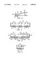
- FIG. 1is a perspective view illustrating a preferred embodiment of the invention in operation
- FIG. 2is a top plan view of the embodiment of FIG. 1;
- FIG. 3is a side elevation view in section taken generally on line 3--3 of FIG. 2;
- FIG. 4is an elevation view taken generally on line 4--4 of FIG. 2;
- FIG. 5is a front elevation view of the housing of the embodiment of FIG. 1;
- FIG. 6is a partial detailed view in section like FIG. 4 illustrating an alternate modification.
- a typical IV infusion site(typically called IV site), as illustrated, comprises an IV needle 12 inserted in a vein of a patient's arm, with a short catheter or length of tubing 14 connected thereto and having a connector 16, such as an infusion port or cap on an outer end thereof for connection of an infusion pump or device.
- the IV site needle and catheter unitare typically held in place by one or more strips of tape or the like 13 and 15, and may include one or more protective covers (not shown).
- the connector 16may be of the type for penetrating by a needle or the like, or it may be of the luer lock type for detachable connection to an infuser.
- a flush system in accordance with the inventioncomprises a reservoir assembly having an integral tubing array for connection to an IV site.
- the tubing arraycomprises a first section of tubing 20 having a first or proximal end 22 for connection to the catheter 14, and a Y coupling 24 including a coupling 26 for connection of an infusion device, and a tubing 28 having a Y coupling 30 connected to the flush system reservoirs 34 and 36.
- the reservoir assemblyis a unitary structure of impervious pliable material formed into two reservoirs 34 and 36.
- the reservoir assemblyis illustrated in FIG. 2 in a transparent housing.
- the overall reservoiris a generally rectangular pliable bag, with the walls sealed together along a line 35 to form reservoirs 34 and 36.
- the reservoir 34is separated along a line 38 into two connected chambers.
- the reservoir 34 with its two chambersis designed for two saline charges of about 3 ml each, and the reservoir 36 is designed for a heparin charge of about 3 ml.
- reservoirsare preferably of a pliable impervious material, such as PVC, typically used for IV bags and the like.
- the two chambers of reservoir 34are permanently connected via a tube 37 to a Y coupling 30 and common tube 28.
- the reservoir 36is likewise permanently connected via tube 39 to Y coupling 30 and common tube 28.
- the systemis a closed system capable of performing its functions with a one time connection. The system requires only a single one time connection at 16, 22 for connecting three charges of fluid to the IV site.
- the infusion device 40can be connected to the IV site at 26 at the same time that the flush system is connected.
- Any suitable IV infusion device 40such as for example of the type disclosed in co-pending application Ser. No. 07/492,982, filed Mar. 12, 1990, now U S. Pat. No. 5,080,652, granted Jan. 14, 1992, and assigned to the assignee hereof, is connected by a usual tubing or line 42 to the infusion coupling 26.
- This couplingis by suitable means, such as a needle cap or a luer lock.
- the flush systemmay be utilized with any suitable infuser.
- the housing 32 of the flushing device 32is preferably of a generally rectangular configuration in top or plan view, and of a generally triangular cross section configuration in side view (FIG. 3).
- the housingis preferably constructed of a transparent rigid plastic.
- the housinghas triangular end walls 44 and 46, and generally rectangular front and back walls 48 and 50 extending upward from a generally planar rectangular bottom wall 52, forming a generally triangular, or more particularly wedge shaped cavity or chamber in which the reservoirs 34 and 36 are disposed.
- a top wallis formed of multiple panels or sections 54, 56 and 58.
- the panels or sections 54 and 56overlie and are co-planar with the two chambers of saline reservoir 34, and the panel 58 is co-planar with the heparin reservoir 36.
- These panelsare each hingedly or pivotally secured along the front to the lower edge of the front wall 48 by suitable tabs and slots. The back edge of each panel engages latching wedges on the inside top and bottom of the back wall 50.
- the back wall 50is formed of three spring panels 60, 62, and 64 by U-shaped slots 66, 68 and 70.
- Each of the spring panelsare provided with a pair of upper wedge shaped latch shoulders 72, 74 and 76 for latching the upper or top wall panels 54, 56 and 58 in an initial assembled position, as seen in FIG. 3.
- a lower latch shoulder 78, 80 and 82is provided at the lower edge of each panel to latch the top wall panels in the collapsed position.
- Intermediate latch notchesmay be provided (i.e. between 72 and 78), refer to FIG. 6, so that each reservoir may have multiple charges.
- the front wall 48is provided with a plurality of rectangular slots 84, 86, 88, 90, 92 and 94.
- Each of the top wall panelsis provided with a pair of tabs 96, 98, 100, 102, 104 and 106 which extend into the slots for hinging the respective panels in the housing.
- a pair of slots 108 and 110 in the front wall 48 and bottom 52, and matching slots 112 and 114 in top panels 54 and 58provide a pair of openings through which filler ports 116 and 118 for bladder reservoirs 34 and 36 extend.
- the housingis thus constructed to have collapsible top walls, such that the sections of the wall can be selectively collapsed against the reservoirs, forcing a liquid therefrom.
- each of the top wall panels 54, 56 and 58may be pressed downward by the fingers or other suitable means, such as a spring to latch in a position closely adjacent the lower wall of the housing, thereby forcing the liquid from the respective reservoirs.
- the walls 54, 56 and 58may be selectively pushed downward, expelling a charge of the fluid from the space beneath the respective panel, and latched in a lower position to effectively force a selected portion or all of the liquid from the respective reservoir or portion thereof.
- the reservoir 34in the illustrated embodiment, is designed to hold two charges (in adjacent portion of the reservoir), with panels or walls 54 and 56 effective in sequence to respectfully discharge these charges.
- the first panel pressed down, preferably 54expels half of the contents or charge and the second panel expels the remainder.
- each panelmay be effective to expel two or more charges, as explained above.
- other meanssuch as rollers or merely opposed panels, may be utilized to collapse the walls of the reservoirs and expel fluid therefrom.
- the reservoirsare each provided with suitable valves, which may be built into the housing (not shown) or such as clamps 120 and 128.
- the back wallis modified to provide latch bumps or shoulders 130 intermediate the latch shoulders 72' and 78' on the spring latch panel 60'.
- latch bumps or shoulders 130intermediate the latch shoulders 72' and 78' on the spring latch panel 60'.
- a flush kit in accordance with the inventionis factory assembled, with a pair of reservoirs 34 and 36 placed in the housing, with tube assembly 20, 22, 28 and 30 attached thereto.
- the top panels 54, 56 and 58are put in place by inserting the tabs into the slots and pressing the panel down, so that the back edge snaps over the top shoulder wedges 72, 74 and 76
- theyare filled by a pharmacist via fill ports 116 and 118 and delivered to a health care official or patient for use in IV therapy.
- an IV siteis or has been installed by medical or health care personnel and left in place for successive IV treatment.
- the patientselects a fresh filled flush kit, and the end 22 of tubing 20 is connected at cap 16 to the IV site.
- an infuser 40is attached at coupling 26 to the flush kit.
- the IV siteis first flushed by opening a valve or clamp 120 on the saline feeding tube, and then pressing down on panel 54 with the fingers until the fluid is expelled, and the panel is latched beneath the lower latch notch 78.
- the clamp 120is then reclosed and infusion may begin by releasing a clamp 122 on an infusion apparatus tubing 42 to feed the IV solution from an infuser or infusion apparatus 40.
- the infusermay be of any suitable type, but is preferably of the inflatable bladder type having an inflatable bladder within a housing.
- One preferred typeis that of the aforementioned application wherein the inflatable bladder 124 is mounted within a substantially or generally spherical housing or shell 126.
- the term substantially or generally sphericalis not intended to connote spherical with mathematical precision, but is intended to allow variation within practical limits.
- the siteis again flushed with a saline solution (about 3 ml) by again opening clamp 120, and then depressing the second panel 56 until remaining fluid is expelled, and the panel 56 is latched beneath the latch notch or tab 80, and the saline reservoir is thus empty.
- the clamp 120is then reapplied to the tubing, and clamp 128 from the heparin reservoir 36 is then opened.
- the panel 58is then depressed with the fingers until the heparin has been forced from the reservoir, the panel latched beneath latch notch 82, and the heparin has been forced into the IV site.
- the flush unitmay now be removed from the cap 16, and it together with the infusion apparatus disposed of in the usual manner.
- the present systemwas devised primarily for use as a flush system, as described above. However, it may have many other uses, such as infusion of micro doses of different drugs sequentially.
- the systemmay also be constructed to have any number of reservoirs and/or chambers.
Landscapes
- Health & Medical Sciences (AREA)
- Vascular Medicine (AREA)
- Engineering & Computer Science (AREA)
- Anesthesiology (AREA)
- Biomedical Technology (AREA)
- Heart & Thoracic Surgery (AREA)
- Hematology (AREA)
- Life Sciences & Earth Sciences (AREA)
- Animal Behavior & Ethology (AREA)
- General Health & Medical Sciences (AREA)
- Public Health (AREA)
- Veterinary Medicine (AREA)
- Infusion, Injection, And Reservoir Apparatuses (AREA)
Abstract
Description
Claims (19)
Priority Applications (1)
| Application Number | Priority Date | Filing Date | Title |
|---|---|---|---|
| US07/842,443US5308334A (en) | 1990-12-27 | 1992-02-27 | Closed system for iv site flush |
Applications Claiming Priority (2)
| Application Number | Priority Date | Filing Date | Title |
|---|---|---|---|
| US63440890A | 1990-12-27 | 1990-12-27 | |
| US07/842,443US5308334A (en) | 1990-12-27 | 1992-02-27 | Closed system for iv site flush |
Related Parent Applications (1)
| Application Number | Title | Priority Date | Filing Date |
|---|---|---|---|
| US63440890AContinuation | 1990-12-27 | 1990-12-27 |
Publications (1)
| Publication Number | Publication Date |
|---|---|
| US5308334Atrue US5308334A (en) | 1994-05-03 |
Family
ID=24543661
Family Applications (1)
| Application Number | Title | Priority Date | Filing Date |
|---|---|---|---|
| US07/842,443Expired - LifetimeUS5308334A (en) | 1990-12-27 | 1992-02-27 | Closed system for iv site flush |
Country Status (4)
| Country | Link |
|---|---|
| US (1) | US5308334A (en) |
| EP (1) | EP0564567A1 (en) |
| CA (1) | CA2099596A1 (en) |
| WO (1) | WO1992011881A1 (en) |
Cited By (30)
| Publication number | Priority date | Publication date | Assignee | Title |
|---|---|---|---|---|
| US5439460A (en)* | 1993-09-07 | 1995-08-08 | Hoover; Bryan J. | Cross-spike prevention system |
| US5701937A (en)* | 1992-11-09 | 1997-12-30 | Pharmacia & Upjohn Aktiebolag | Fluid distribution system |
| US5788215A (en)* | 1995-12-29 | 1998-08-04 | Rymed Technologies | Medical intravenous administration line connectors having a luer or pressure activated valve |
| US5833213A (en)* | 1995-12-29 | 1998-11-10 | Rymed Technologies, Inc. | Multiple dose drug vial adapter for use with a vial having a pierceable septum and a needleless syringe |
| US5954313A (en)* | 1995-12-29 | 1999-09-21 | Rymed Technologies, Inc. | Medical intravenous administration line connectors having a luer activated valve |
| US6074366A (en)* | 1998-01-16 | 2000-06-13 | Tandem Medical Inc. | Medication delivery apparatus |
| US6238374B1 (en) | 1999-08-06 | 2001-05-29 | Proxima Therapeutics, Inc. | Hazardous fluid infuser |
| US6391001B1 (en) | 2000-09-21 | 2002-05-21 | Jolie Graham | Intravenous line flushing device |
| US6428518B1 (en) | 1999-11-05 | 2002-08-06 | Tandem Medical | Medication delivery container |
| US6471674B1 (en)* | 2000-04-21 | 2002-10-29 | Medrad, Inc. | Fluid delivery systems, injector systems and methods of fluid delivery |
| US6726655B1 (en) | 1999-11-05 | 2004-04-27 | Tandem Medical | Medication delivery system |
| US6783514B2 (en)* | 1997-01-31 | 2004-08-31 | United States Surgical Corporation | Fibrin sealant applicator |
| US20060163515A1 (en)* | 2003-06-17 | 2006-07-27 | Ruschke Ricky R | Fluid handling device and method of making same |
| US20070299408A1 (en)* | 2006-03-16 | 2007-12-27 | Seattle Medical Technologies | Infusion device pump |
| US7530968B2 (en) | 2003-04-23 | 2009-05-12 | Valeritas, Inc. | Hydraulically actuated pump for long duration medicament administration |
| DE102008063592A1 (en) | 2008-12-18 | 2010-06-24 | Schindelhauer, Dirk, Dr. | Sterile process bag for carrying out a multistage process in a closed system, comprises a carrier matrix with biomolecules to be cleaned in the bag, and an electrode pluggable channel and/or buffer bridges for electro-elution |
| US20100228207A1 (en)* | 2005-09-07 | 2010-09-09 | Cabochon Aesthetics, Inc. | Fluid-jet dissection system and method for reducing the appearance of cellulite |
| US20100286650A1 (en)* | 2009-05-07 | 2010-11-11 | Alan Fitzgerald | Medical Fluid Container |
| US7914499B2 (en) | 2006-03-30 | 2011-03-29 | Valeritas, Inc. | Multi-cartridge fluid delivery device |
| US9089636B2 (en) | 2004-07-02 | 2015-07-28 | Valeritas, Inc. | Methods and devices for delivering GLP-1 and uses thereof |
| US9108047B2 (en) | 2010-06-04 | 2015-08-18 | Bayer Medical Care Inc. | System and method for planning and monitoring multi-dose radiopharmaceutical usage on radiopharmaceutical injectors |
| US9272124B2 (en) | 2005-12-02 | 2016-03-01 | Ulthera, Inc. | Systems and devices for selective cell lysis and methods of using same |
| US9358064B2 (en) | 2009-08-07 | 2016-06-07 | Ulthera, Inc. | Handpiece and methods for performing subcutaneous surgery |
| US9364246B2 (en) | 2005-09-07 | 2016-06-14 | Ulthera, Inc. | Dissection handpiece and method for reducing the appearance of cellulite |
| US10220122B2 (en) | 2007-10-09 | 2019-03-05 | Ulthera, Inc. | System for tissue dissection and aspiration |
| US10531888B2 (en) | 2009-08-07 | 2020-01-14 | Ulthera, Inc. | Methods for efficiently reducing the appearance of cellulite |
| US10548659B2 (en) | 2006-01-17 | 2020-02-04 | Ulthera, Inc. | High pressure pre-burst for improved fluid delivery |
| US11058812B2 (en) | 2017-07-25 | 2021-07-13 | Lydia Begg | Intravenous bag attachment |
| US11096708B2 (en) | 2009-08-07 | 2021-08-24 | Ulthera, Inc. | Devices and methods for performing subcutaneous surgery |
| US11337725B2 (en) | 2009-08-07 | 2022-05-24 | Ulthera, Inc. | Handpieces for tissue treatment |
Families Citing this family (4)
| Publication number | Priority date | Publication date | Assignee | Title |
|---|---|---|---|---|
| US5368570A (en)* | 1991-11-12 | 1994-11-29 | Imed Corporation | Apparatus for infusing medical solutions |
| ATE216605T1 (en)* | 1995-08-25 | 2002-05-15 | Debiotech Sa | DEVICE FOR CONTINUOUS INJECTION |
| FR2794983B1 (en)* | 1999-06-18 | 2001-12-28 | Maco Pharma Sa | MULTIPLE POCKET PERFUSION KIT |
| FR2871062B1 (en)* | 2004-06-02 | 2006-09-08 | Aguettant Soc Par Actions Simp | INFUSION POCKET WITH INTEGRATED RINSE |
Citations (22)
| Publication number | Priority date | Publication date | Assignee | Title |
|---|---|---|---|---|
| US1102953A (en)* | 1912-10-30 | 1914-07-07 | Milford J Rabat | Fountain-syringe pressure-clamp. |
| US1546016A (en)* | 1924-10-20 | 1925-07-14 | Eisele Edward | Fountain syringe |
| US3194440A (en)* | 1963-10-11 | 1965-07-13 | Jr Cornelins B Watson | Plurality of tube squeezers and holder therefor |
| US3442424A (en)* | 1967-08-31 | 1969-05-06 | Rexall Drug Chemical | Multiple compartment collapsible tubes |
| US3595232A (en)* | 1968-08-19 | 1971-07-27 | Saul Leibinsohn | Nongravitational infusion assembly |
| US3734351A (en)* | 1970-08-03 | 1973-05-22 | Labaz | Press for a deformable bag |
| US3780730A (en)* | 1971-05-28 | 1973-12-25 | A Weisman | Contraceptive |
| CA1013635A (en)* | 1973-11-16 | 1977-07-12 | Derek J. Kidd | Subcutaneous infusion system |
| US4044757A (en)* | 1976-01-14 | 1977-08-30 | The Kendall Company | Cholangiography device and method |
| US4187845A (en)* | 1978-07-12 | 1980-02-12 | Dror Leon L | Apparatus for feeding anesthetic and/or life sustaining gases during a surgical procedure |
| DE3238649A1 (en)* | 1982-10-19 | 1984-04-19 | Hagen Dr. 8520 Erlangen Theuer | Multicompartment bag for mixed infusion solutions |
| US4504267A (en)* | 1980-11-28 | 1985-03-12 | Parmelee William H | Apparatus for intravenous injection of liquids |
| US4512764A (en)* | 1982-09-27 | 1985-04-23 | Wunsch Richard E | Manifold for controlling administration of multiple intravenous solutions and medications |
| US4576603A (en)* | 1984-06-18 | 1986-03-18 | Gerald Moss | Feeding device for enterally administering liquids into a human body |
| FR2570279A1 (en)* | 1984-09-18 | 1986-03-21 | Haegy Jean Marie | Plastic bag for parenteral supply |
| US4666430A (en)* | 1984-12-05 | 1987-05-19 | I-Flow Corporation | Infusion pump |
| US4753371A (en)* | 1983-11-02 | 1988-06-28 | Serge Michielin | Flow controlled and container |
| US4830510A (en)* | 1983-10-31 | 1989-05-16 | Bellhouse Brian John | Optical assay method for stored human platelets |
| US4857055A (en)* | 1986-04-15 | 1989-08-15 | Wang Paul Y | Compression device enabling flexible solution containers to produce constant delivery rate |
| US4915688A (en)* | 1987-12-03 | 1990-04-10 | Baxter International Inc. | Apparatus for administering solution to a patient |
| US4957436A (en)* | 1986-03-28 | 1990-09-18 | National Patent Development Corporation | Dental pump system for chemical caries removal |
| US4997083A (en)* | 1987-05-29 | 1991-03-05 | Vifor S.A. | Container intended for the separate storage of active compositions and for their subsequent mixing |
Family Cites Families (5)
| Publication number | Priority date | Publication date | Assignee | Title |
|---|---|---|---|---|
| DE3519128A1 (en)* | 1985-05-28 | 1986-12-04 | Yen-Cheng Dr.med. 6650 Homburg Wu | Device for the aseptic handling of the connectors of transfer devices on exchange of bags during continuous ambulatory peritoneal dialysis (CAPD), and plastic bag filled with dialysate |
| GB8602732D0 (en)* | 1986-02-04 | 1986-03-12 | Univ Brunel | Taking samples from patients |
| US4666429A (en)* | 1986-02-26 | 1987-05-19 | Intelligent Medicine, Inc. | Infusion device having improved valving apparatus |
| EP0609904A1 (en)* | 1986-10-17 | 1994-08-10 | PATTULLO, Norman | Method of manufacturing a flexible tube |
| US4758235A (en)* | 1987-05-26 | 1988-07-19 | Tu Ho C | Cardiopulmonary resuscitation medication assembly |
- 1991
- 1991-12-13EPEP92903438Apatent/EP0564567A1/ennot_activeWithdrawn
- 1991-12-13WOPCT/US1991/009350patent/WO1992011881A1/ennot_activeApplication Discontinuation
- 1991-12-13CACA002099596Apatent/CA2099596A1/ennot_activeAbandoned
- 1992
- 1992-02-27USUS07/842,443patent/US5308334A/ennot_activeExpired - Lifetime
Patent Citations (22)
| Publication number | Priority date | Publication date | Assignee | Title |
|---|---|---|---|---|
| US1102953A (en)* | 1912-10-30 | 1914-07-07 | Milford J Rabat | Fountain-syringe pressure-clamp. |
| US1546016A (en)* | 1924-10-20 | 1925-07-14 | Eisele Edward | Fountain syringe |
| US3194440A (en)* | 1963-10-11 | 1965-07-13 | Jr Cornelins B Watson | Plurality of tube squeezers and holder therefor |
| US3442424A (en)* | 1967-08-31 | 1969-05-06 | Rexall Drug Chemical | Multiple compartment collapsible tubes |
| US3595232A (en)* | 1968-08-19 | 1971-07-27 | Saul Leibinsohn | Nongravitational infusion assembly |
| US3734351A (en)* | 1970-08-03 | 1973-05-22 | Labaz | Press for a deformable bag |
| US3780730A (en)* | 1971-05-28 | 1973-12-25 | A Weisman | Contraceptive |
| CA1013635A (en)* | 1973-11-16 | 1977-07-12 | Derek J. Kidd | Subcutaneous infusion system |
| US4044757A (en)* | 1976-01-14 | 1977-08-30 | The Kendall Company | Cholangiography device and method |
| US4187845A (en)* | 1978-07-12 | 1980-02-12 | Dror Leon L | Apparatus for feeding anesthetic and/or life sustaining gases during a surgical procedure |
| US4504267A (en)* | 1980-11-28 | 1985-03-12 | Parmelee William H | Apparatus for intravenous injection of liquids |
| US4512764A (en)* | 1982-09-27 | 1985-04-23 | Wunsch Richard E | Manifold for controlling administration of multiple intravenous solutions and medications |
| DE3238649A1 (en)* | 1982-10-19 | 1984-04-19 | Hagen Dr. 8520 Erlangen Theuer | Multicompartment bag for mixed infusion solutions |
| US4830510A (en)* | 1983-10-31 | 1989-05-16 | Bellhouse Brian John | Optical assay method for stored human platelets |
| US4753371A (en)* | 1983-11-02 | 1988-06-28 | Serge Michielin | Flow controlled and container |
| US4576603A (en)* | 1984-06-18 | 1986-03-18 | Gerald Moss | Feeding device for enterally administering liquids into a human body |
| FR2570279A1 (en)* | 1984-09-18 | 1986-03-21 | Haegy Jean Marie | Plastic bag for parenteral supply |
| US4666430A (en)* | 1984-12-05 | 1987-05-19 | I-Flow Corporation | Infusion pump |
| US4957436A (en)* | 1986-03-28 | 1990-09-18 | National Patent Development Corporation | Dental pump system for chemical caries removal |
| US4857055A (en)* | 1986-04-15 | 1989-08-15 | Wang Paul Y | Compression device enabling flexible solution containers to produce constant delivery rate |
| US4997083A (en)* | 1987-05-29 | 1991-03-05 | Vifor S.A. | Container intended for the separate storage of active compositions and for their subsequent mixing |
| US4915688A (en)* | 1987-12-03 | 1990-04-10 | Baxter International Inc. | Apparatus for administering solution to a patient |
Cited By (59)
| Publication number | Priority date | Publication date | Assignee | Title |
|---|---|---|---|---|
| US5701937A (en)* | 1992-11-09 | 1997-12-30 | Pharmacia & Upjohn Aktiebolag | Fluid distribution system |
| US5439460A (en)* | 1993-09-07 | 1995-08-08 | Hoover; Bryan J. | Cross-spike prevention system |
| US6158458A (en)* | 1995-12-29 | 2000-12-12 | Ryan; Dana Wm. | Medical intravenous administration line connectors having a luer or pressure activated valve |
| US5788215A (en)* | 1995-12-29 | 1998-08-04 | Rymed Technologies | Medical intravenous administration line connectors having a luer or pressure activated valve |
| US5833213A (en)* | 1995-12-29 | 1998-11-10 | Rymed Technologies, Inc. | Multiple dose drug vial adapter for use with a vial having a pierceable septum and a needleless syringe |
| US5954313A (en)* | 1995-12-29 | 1999-09-21 | Rymed Technologies, Inc. | Medical intravenous administration line connectors having a luer activated valve |
| US6783514B2 (en)* | 1997-01-31 | 2004-08-31 | United States Surgical Corporation | Fibrin sealant applicator |
| US6146360A (en)* | 1998-01-16 | 2000-11-14 | Tandem Medical, Inc. | Medication delivery apparatus |
| US6416496B1 (en) | 1998-01-16 | 2002-07-09 | Tandem Medical, Inc. | Medication delivery apparatus |
| US6074366A (en)* | 1998-01-16 | 2000-06-13 | Tandem Medical Inc. | Medication delivery apparatus |
| US6238374B1 (en) | 1999-08-06 | 2001-05-29 | Proxima Therapeutics, Inc. | Hazardous fluid infuser |
| US6589158B2 (en) | 1999-08-06 | 2003-07-08 | Proxima Therapeutics, Inc. | Radiation shield for a syringe |
| US6726655B1 (en) | 1999-11-05 | 2004-04-27 | Tandem Medical | Medication delivery system |
| US6428518B1 (en) | 1999-11-05 | 2002-08-06 | Tandem Medical | Medication delivery container |
| US6471674B1 (en)* | 2000-04-21 | 2002-10-29 | Medrad, Inc. | Fluid delivery systems, injector systems and methods of fluid delivery |
| US6699219B2 (en) | 2000-04-21 | 2004-03-02 | Medrad, Inc. | Fluid delivery systems, injector systems and methods of fluid delivery |
| US6972001B2 (en) | 2000-04-21 | 2005-12-06 | Medrad, Inc. | Fluid delivery system having pump systems, check valves and a removable patient interface |
| US6391001B1 (en) | 2000-09-21 | 2002-05-21 | Jolie Graham | Intravenous line flushing device |
| US11642456B2 (en) | 2003-04-23 | 2023-05-09 | Mannkind Corporation | Hydraulically actuated pump for fluid administration |
| US10525194B2 (en) | 2003-04-23 | 2020-01-07 | Valeritas, Inc. | Hydraulically actuated pump for fluid administration |
| US9511187B2 (en) | 2003-04-23 | 2016-12-06 | Valeritas, Inc. | Hydraulically actuated pump for fluid administration |
| US9125983B2 (en) | 2003-04-23 | 2015-09-08 | Valeritas, Inc. | Hydraulically actuated pump for fluid administration |
| US7530968B2 (en) | 2003-04-23 | 2009-05-12 | Valeritas, Inc. | Hydraulically actuated pump for long duration medicament administration |
| US9072828B2 (en) | 2003-04-23 | 2015-07-07 | Valeritas, Inc. | Hydraulically actuated pump for long duration medicament administration |
| US8070726B2 (en) | 2003-04-23 | 2011-12-06 | Valeritas, Inc. | Hydraulically actuated pump for long duration medicament administration |
| US8038123B2 (en) | 2003-06-17 | 2011-10-18 | Filtertek Inc. | Fluid handling device and method of making same |
| US7520489B2 (en) | 2003-06-17 | 2009-04-21 | Filtertek Inc. | Fluid handling device and method of making same |
| US20060163515A1 (en)* | 2003-06-17 | 2006-07-27 | Ruschke Ricky R | Fluid handling device and method of making same |
| US20090184275A1 (en)* | 2003-06-17 | 2009-07-23 | Filtertek Inc. | Fluid handling device and method of making same |
| US9089636B2 (en) | 2004-07-02 | 2015-07-28 | Valeritas, Inc. | Methods and devices for delivering GLP-1 and uses thereof |
| US20100228207A1 (en)* | 2005-09-07 | 2010-09-09 | Cabochon Aesthetics, Inc. | Fluid-jet dissection system and method for reducing the appearance of cellulite |
| US9364246B2 (en) | 2005-09-07 | 2016-06-14 | Ulthera, Inc. | Dissection handpiece and method for reducing the appearance of cellulite |
| US9358033B2 (en)* | 2005-09-07 | 2016-06-07 | Ulthera, Inc. | Fluid-jet dissection system and method for reducing the appearance of cellulite |
| US9272124B2 (en) | 2005-12-02 | 2016-03-01 | Ulthera, Inc. | Systems and devices for selective cell lysis and methods of using same |
| US10548659B2 (en) | 2006-01-17 | 2020-02-04 | Ulthera, Inc. | High pressure pre-burst for improved fluid delivery |
| US20070299408A1 (en)* | 2006-03-16 | 2007-12-27 | Seattle Medical Technologies | Infusion device pump |
| US8758308B2 (en) | 2006-03-16 | 2014-06-24 | Calibra Medical, Inc. | Infusion device pump |
| WO2007108991A3 (en)* | 2006-03-16 | 2008-11-27 | Calibra Medical Inc | Infusion device with dome pump |
| US9687599B2 (en) | 2006-03-30 | 2017-06-27 | Valeritas, Inc. | Multi-cartridge fluid delivery device |
| US8821443B2 (en) | 2006-03-30 | 2014-09-02 | Valeritas, Inc. | Multi-cartridge fluid delivery device |
| US7914499B2 (en) | 2006-03-30 | 2011-03-29 | Valeritas, Inc. | Multi-cartridge fluid delivery device |
| US8361053B2 (en) | 2006-03-30 | 2013-01-29 | Valeritas, Inc. | Multi-cartridge fluid delivery device |
| US10220122B2 (en) | 2007-10-09 | 2019-03-05 | Ulthera, Inc. | System for tissue dissection and aspiration |
| DE102008063592A1 (en) | 2008-12-18 | 2010-06-24 | Schindelhauer, Dirk, Dr. | Sterile process bag for carrying out a multistage process in a closed system, comprises a carrier matrix with biomolecules to be cleaned in the bag, and an electrode pluggable channel and/or buffer bridges for electro-elution |
| US20100286650A1 (en)* | 2009-05-07 | 2010-11-11 | Alan Fitzgerald | Medical Fluid Container |
| US10531888B2 (en) | 2009-08-07 | 2020-01-14 | Ulthera, Inc. | Methods for efficiently reducing the appearance of cellulite |
| US11096708B2 (en) | 2009-08-07 | 2021-08-24 | Ulthera, Inc. | Devices and methods for performing subcutaneous surgery |
| US9510849B2 (en) | 2009-08-07 | 2016-12-06 | Ulthera, Inc. | Devices and methods for performing subcutaneous surgery |
| US10271866B2 (en) | 2009-08-07 | 2019-04-30 | Ulthera, Inc. | Modular systems for treating tissue |
| US10485573B2 (en) | 2009-08-07 | 2019-11-26 | Ulthera, Inc. | Handpieces for tissue treatment |
| US9358064B2 (en) | 2009-08-07 | 2016-06-07 | Ulthera, Inc. | Handpiece and methods for performing subcutaneous surgery |
| US11337725B2 (en) | 2009-08-07 | 2022-05-24 | Ulthera, Inc. | Handpieces for tissue treatment |
| US9757145B2 (en) | 2009-08-07 | 2017-09-12 | Ulthera, Inc. | Dissection handpiece and method for reducing the appearance of cellulite |
| US10603066B2 (en)* | 2010-05-25 | 2020-03-31 | Ulthera, Inc. | Fluid-jet dissection system and method for reducing the appearance of cellulite |
| US20160249946A1 (en)* | 2010-05-25 | 2016-09-01 | Ulthera, Inc. | Fluid-jet dissection system and method for reducing the appearance of cellulite |
| US9108047B2 (en) | 2010-06-04 | 2015-08-18 | Bayer Medical Care Inc. | System and method for planning and monitoring multi-dose radiopharmaceutical usage on radiopharmaceutical injectors |
| US9463335B2 (en) | 2010-06-04 | 2016-10-11 | Bayer Healthcare Llc | System and method for planning and monitoring multi-dose radiopharmaceutical usage on radiopharmaceutical injectors |
| US11213618B2 (en) | 2010-12-22 | 2022-01-04 | Ulthera, Inc. | System for tissue dissection and aspiration |
| US11058812B2 (en) | 2017-07-25 | 2021-07-13 | Lydia Begg | Intravenous bag attachment |
Also Published As
| Publication number | Publication date |
|---|---|
| WO1992011881A1 (en) | 1992-07-23 |
| EP0564567A1 (en) | 1993-10-13 |
| CA2099596A1 (en) | 1992-06-28 |
Similar Documents
| Publication | Publication Date | Title |
|---|---|---|
| US5308334A (en) | Closed system for iv site flush | |
| EP0412994B1 (en) | Dual access infusion and monitoring system | |
| US4610666A (en) | Dual syringe | |
| EP1527794B1 (en) | Refill kit for an implantable pump | |
| US5439452A (en) | Limit stop valve infusion device | |
| JP2736509B2 (en) | In-line drug release device and release method for use with a standard intravenous set | |
| CA1155023A (en) | I.v. administration set with retrograde volume | |
| JP2736510B2 (en) | In-line drug release device and release method for use with a standard intravenous set | |
| AU628054B2 (en) | Implantable infusion apparatus | |
| US5419771A (en) | Fluid delivery apparatus and support assembly | |
| US5032117A (en) | Tandem syringe | |
| US4609371A (en) | Dual syringe for either simultaneous or sequential injection of liquids | |
| US5116316A (en) | Automatic in-line reconstitution system | |
| US5368570A (en) | Apparatus for infusing medical solutions | |
| US4687468A (en) | Implantable insulin administration device | |
| US6500156B1 (en) | Thumb-powered flushing device for catheters | |
| JPH10248928A (en) | Medical fluid supply jig and priming device | |
| JPH067722Y2 (en) | Continuous drug infusion device with bellows container | |
| EP0245056A1 (en) | Ambulatory disposable infusion pump | |
| JP2807698B2 (en) | Implantable liquid injector |
Legal Events
| Date | Code | Title | Description |
|---|---|---|---|
| AS | Assignment | Owner name:BLOCK MEDICAL, INC., CALIFORNIA Free format text:ASSIGNMENT OF ASSIGNORS INTEREST.;ASSIGNOR:SANCOFF, GREGORY E.;REEL/FRAME:006046/0977 Effective date:19920226 | |
| STCF | Information on status: patent grant | Free format text:PATENTED CASE | |
| AS | Assignment | Owner name:SILICON VALLEY BANK, CALIFORNIA Free format text:SECURITY INTEREST;ASSIGNOR:I-FLOW CORPORATION;REEL/FRAME:008059/0527 Effective date:19960718 | |
| FPAY | Fee payment | Year of fee payment:4 | |
| FEPP | Fee payment procedure | Free format text:PAT HOLDER CLAIMS SMALL ENTITY STATUS - SMALL BUSINESS (ORIGINAL EVENT CODE: SM02); ENTITY STATUS OF PATENT OWNER: SMALL ENTITY | |
| AS | Assignment | Owner name:I-FLOW CORPORATION, CALIFORNIA Free format text:ASSIGNMENT OF ASSIGNORS INTEREST;ASSIGNORS:BLOCK MEDICAL, INC.;HILLENBRAND INDUSTRIES, INC.;REEL/FRAME:009314/0660 Effective date:19960722 | |
| FPAY | Fee payment | Year of fee payment:8 | |
| FEPP | Fee payment procedure | Free format text:PAYOR NUMBER ASSIGNED (ORIGINAL EVENT CODE: ASPN); ENTITY STATUS OF PATENT OWNER: SMALL ENTITY Free format text:PAT HOLDER CLAIMS SMALL ENTITY STATUS, ENTITY STATUS SET TO SMALL (ORIGINAL EVENT CODE: LTOS); ENTITY STATUS OF PATENT OWNER: SMALL ENTITY Free format text:PAT HOLDER NO LONGER CLAIMS SMALL ENTITY STATUS, ENTITY STATUS SET TO UNDISCOUNTED (ORIGINAL EVENT CODE: STOL); ENTITY STATUS OF PATENT OWNER: SMALL ENTITY | |
| FPAY | Fee payment | Year of fee payment:12 | |
| FEPP | Fee payment procedure | Free format text:ENTITY STATUS SET TO UNDISCOUNTED (ORIGINAL EVENT CODE: BIG.); ENTITY STATUS OF PATENT OWNER: SMALL ENTITY | |
| AS | Assignment | Owner name:I-FLOW CORPORATION, CALIFORNIA Free format text:RELEASE BY SECURED PARTY;ASSIGNOR:SILICON VALLEY BANK;REEL/FRAME:023639/0135 Effective date:20091125 |