US5308304A - Multi-hip exerciser - Google Patents
Multi-hip exerciserDownload PDFInfo
- Publication number
- US5308304A US5308304AUS07/918,251US91825192AUS5308304AUS 5308304 AUS5308304 AUS 5308304AUS 91825192 AUS91825192 AUS 91825192AUS 5308304 AUS5308304 AUS 5308304A
- Authority
- US
- United States
- Prior art keywords
- cable
- sleeve
- frame
- floating
- pulley
- Prior art date
- Legal status (The legal status is an assumption and is not a legal conclusion. Google has not performed a legal analysis and makes no representation as to the accuracy of the status listed.)
- Expired - Lifetime
Links
- 230000033001locomotionEffects0.000claimsabstractdescription13
- 238000006073displacement reactionMethods0.000description8
- 230000007423decreaseEffects0.000description3
- 229910000831SteelInorganic materials0.000description1
- 238000010276constructionMethods0.000description1
- 239000002184metalSubstances0.000description1
- 238000000034methodMethods0.000description1
- 238000012986modificationMethods0.000description1
- 230000004048modificationEffects0.000description1
- 210000003205muscleAnatomy0.000description1
- 239000010959steelSubstances0.000description1
Images


Classifications
- A—HUMAN NECESSITIES
- A63—SPORTS; GAMES; AMUSEMENTS
- A63B—APPARATUS FOR PHYSICAL TRAINING, GYMNASTICS, SWIMMING, CLIMBING, OR FENCING; BALL GAMES; TRAINING EQUIPMENT
- A63B21/00—Exercising apparatus for developing or strengthening the muscles or joints of the body by working against a counterforce, with or without measuring devices
- A63B21/06—User-manipulated weights
- A63B21/062—User-manipulated weights including guide for vertical or non-vertical weights or array of weights to move against gravity forces
- A63B21/0626—User-manipulated weights including guide for vertical or non-vertical weights or array of weights to move against gravity forces with substantially vertical guiding means
- A63B21/0628—User-manipulated weights including guide for vertical or non-vertical weights or array of weights to move against gravity forces with substantially vertical guiding means for vertical array of weights
- Y—GENERAL TAGGING OF NEW TECHNOLOGICAL DEVELOPMENTS; GENERAL TAGGING OF CROSS-SECTIONAL TECHNOLOGIES SPANNING OVER SEVERAL SECTIONS OF THE IPC; TECHNICAL SUBJECTS COVERED BY FORMER USPC CROSS-REFERENCE ART COLLECTIONS [XRACs] AND DIGESTS
- Y10—TECHNICAL SUBJECTS COVERED BY FORMER USPC
- Y10S—TECHNICAL SUBJECTS COVERED BY FORMER USPC CROSS-REFERENCE ART COLLECTIONS [XRACs] AND DIGESTS
- Y10S482/00—Exercise devices
- Y10S482/908—Adjustable
Definitions
- the present inventionrelates to exercising equipment, in particular a weight lifting machine.
- Lifting weightshas been a historic method of building and toning body muscles. Over the years weight lifting machines have been developed to provide controlled lifting motions and to remove the bulkiness of "free style" weight lifting. A typical weight lifting machine utilizes cables and pulleys to convert human body movement into a vertical translation of weights.
- U.S. Pat. No. 5,067,708 issued to Oschanskydiscloses an exercise machine that incorporates three cables and a series of pulleys that vertically lift a weight stack in response to the angular displacement of an actuating arm.
- the Oschansky deviceincludes a frame and an actuator arm assembly that can be adjusted to a number of positions along a vertical bar of the frame. The adjustment means allows the user to vary the height of the actuator arm.
- the actuator arm of the Oschansky machineis attached to a cam that is coupled to a vertical translation plate by a pair of chains.
- the vertical translation plateis coupled to the weight stack by the cable/pulley assembly.
- the cable/pulley assemblyhas a pair of floating pulleys that move when the actuator arm assembly is adjusted so that slack is not created in the system. The pulleys do not displace vertically when the actuator arm is rotated during an exercise routine.
- Rotation of the actuator arm and campulls the translation plate in a downward direction. Movement of the plate pulls the cables and lifts the weight stack.
- the chainsare located off-center from the center line of the plate, so that rotation of the arm and cam in either direction causes one of the chains to pull the translation plate.
- Such an arrangementcreates a torque on the plate.
- the Oschansky deviceprovides rollers that guide and secure the translation plate within a pair of grooves located in the frame of the machine. The rollers and guides create additional components that increase the complexity and cost of the machine. Additionally, because of the limitations of the plate/chain assembly, the actuator arm of the Oschansky machine cannot be rotated more than 180°.
- the present inventionis an exercising machine that has an adjustable actuator arm assembly coupled to a weight stack by a pulley/cable assembly.
- the actuator arm assemblyincludes an actuator arm that lifts the weight stack when rotated through an arc.
- the machineis constructed with a frame that has a vertical bar.
- the actuator armis coupled to a sleeve assembly that can slide along the vertical bar, to provide a number of operating locations.
- the machinehas a first cable that is coupled to the actuator arm. The cable is looped around a first tension pulley, a first floating pulley and then fixed to the sleeve assembly.
- the first floating pulleyis coupled to a second cable that loops around a second tension pulley and is attached to the weight stack.
- the first floating pulleyWhen the actuator arm is rotated, the first floating pulley is pulled in a downward direction. The movement of the first floating pulley pulls the second cable and lifts the weight in a vertical direction.
- the cable lengths between the first tension pulley and actuator arm, and between the first floating pulley and sleevechange an equal and offsetting amount. The offsetting changing cable lengths prevents movement of the floating pulley and insures that the cable is always in tension when the sleeve assembly is adjusted to a new location.
- the present inventionallows the user to adjust the height of the actuator arm without affecting the travel of the pulley or the rotational range of the arm. Additionally, the cable is coupled to the actuator arm, so that the arm can rotate more than 180°.
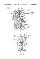
- FIG. 1is a perspective view of an exercise machine of the present invention
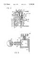
- FIG. 2is a front view of the exercise machine of FIG. 1;
- FIG. 3is a side view of the exercise machine of FIG. 1;
- FIG. 4is a cross-sectional view of the machine of FIG. 1, showing a captured spring loaded pin inserted into the hole of a frame;
- FIG. 5is a perspective view of the exercise machine of FIG. 1, with an actuator arm rotated and weights lifted in a vertical direction;
- FIG. 6is a side view of the exercise machine of FIG. 1 showing the actuator arm moved into a different location;
- FIG. 7is a side view showing an alternate embodiment of the exercise machine of FIG. 1;
- FIG. 8is a side view of another alternate embodiment of the present invention.
- FIG. 1shows an exercise machine 10 of the present invention.
- the machine 10includes a frame 12 typically constructed from a tubular metal such as steel, which provides a strong and relatively lightweight structure.
- the frame 12has a vertical bar 14 rigidly connected to a T shaped base 16.
- a rear support bracket 18is also attached to the base 16 .
- the rear bracket 18may be rounded to improve the safety and appearance of the machine.
- the vertical bar 14 and rear bracket 18are both connected to a handle bracket 20. Extending from the handle bracket 20 are a pair of handle bars 22.
- the bars 22provide an object for the user to grab while operating the machine.
- the surface of the bars 22may be treated or covered to improve the grip of the same.
- the brackets, bar and basecan all be bolted and/or welded together to provide a rigid frame structure.
- the machine 10has a sleeve assembly 24 attached to the frame 12.
- the sleeve assembly 24includes a sleeve 26 that can slide along the vertical bar 14.
- Attached to the top of the sleeve 26is a tubular bearing 28. Extending through the bearing 28 is the axle 30 of an actuator arm 36.
- the axle 30extends through the cam selector plate 32 so that the arm 36 can rotate relative to the plate 32.
- a shaft collar 34is attached to the end of the axle 30 to prevent the arm 36 and cam 32 from becoming detached from the sleeve 26.
- a pad shaft 38Extending from the arm 36 is a pad shaft 38.
- a pad 40may surround the pad shaft 38 to provide comfort for the user.
- the cam selector plate 32may have a plurality of holes 42 arranged in a circular manner.
- the arm 36has a captured spring loaded pin 44 that can be inserted into the wheel holes 42.
- the pin 44can be pulled out of the cam 32 so that the arm 36 can be rotated to change the position of the pad shaft 38 and pad 40.
- the pin 44 and hole 42 arrangementallows the user to adjust the angular position of the arm 36 relative to the cam selector plate 32.
- the vertical bar 14has a plurality of holes 46 that provide a number of sleeve locations.
- the sleeve 26has a pin housing 48 that contains a pin 50 and a spring 52.
- the pin 50extends through the sleeve 26 and can be inserted into one of the bar holes 46.
- the pin 50also has a handle 54 that allows the user to pull the pin 50 out of the hole 46 and move the sleeve 26 relative to the bar 14.
- the pin housing 48is rigidly connected to the sleeve 26 so that when the sleeve 26 is moved, the pin 50 must be displaced.
- the sleeve assembly 24may also have a captured screw 56 that extends through the top portion of the sleeve 26.
- the screw 56has a handle 58 that allows the user to rotate the screw 56 in a clockwise or counterclockwise direction. The screw 56 can engage the vertical bar 14 to further secure the sleeve 26 to the frame 12.
- the userrotates the handle 58 and disengages the screw 56 from the bar 14.
- the pin 50is pulled out of the hole 46 and the sleeve 26 is moved to the desired location.
- the pin handle 54is then released such that the pin 50 enters a new hole 46.
- the pin handle 54may be released in the proximity of the desired location and the sleeve 26 can be moved until the pin 50 "pops" into the new hole 46.
- the screw 56is then rotated to further secure the sleeve 26 to the frame 12.
- the pin 50 and hole 46 arrangementallows the user to move the actuator arm 36 into a variety of vertical locations along the vertical bar 14.
- the sleeve 26may have a bar 59 that provides a handle for the user to grab while moving the actuator arm 38 along the vertical bar 14.
- the machine 10has a first cable 60 with one end attached to the cam selector plate 32 by a pin 62.
- the cable 60loops around a first tension pulley 64 that is attached to the vertical bar 14.
- the first tension pulley 64is allowed to rotate relative to the frame 12.
- the distance from the wheel pin 62 to the first tension pulley 64defines a first cable length 66.
- the sleeve assembly 24may also have a pair of pulleys 68 attached to the sleeve 26 by a bracket 70.
- the pulleys 68keep the cable 60 essentially linear with the bar 14, when the cam selector plate 32 is rotated and the pin 62 moves through an angular displacement.
- the pulleys 68provide a guide for the cable 60, so that the cable 60 has a greater displacement as it goes around the cam 71 of the cam selector plate 32.
- the first cable 60goes from tension pulley 64 and loops around a first floating pulley 72 and is connected to an attachment bracket 74 extending from the sleeve 26.
- the distance from the first tension pulley 64 to the first floating pulley 72defines a second cable length 76.
- the distance from the first floating pulley 72 to the attachment bracket 74defines a third cable length 78.
- the first floating pulley 72is connected to a second floating pulley 80.
- the floating pulleysare each pivotally connected to a pulley bracket 82 that allows the pulleys to freely rotate.
- the second floating pulley 80is suspended from the frame 12 by a second cable 84. In this manner, the first 72 and second 80 floating pulleys are supported by the first 60 and second 84 cables.
- One end of the second cable 84is connected to a first pulley bracket 86 attached to the rear bracket 18.
- the second cable 84loops around a pair of second tension pulleys 88 that are attached to the first pulley bracket 86 and a second pulley bracket 90.
- two separate second tension pulleys 88are described and shown, it is to be understood that a single pulley with a sufficient radius could be utilized.
- the second cable 84is attached to a weight stack 92.
- the weight stack 92is comprised of a number of individual weights 94.
- the weights 94are coupled to a lift plate 96 which is fixed to the cable 84.
- the lift plate 96has a rod (not shown) that extends through the weights 94.
- a pin 98can be inserted between two individual weights to couple a number of weights to the plate 96, as is known in the art.
- Extending from the second pulley bracket 90are a pair of guide bars 100 that guide the weights 94 when the same are lifted in a vertical direction.
- the actuator arm 36moves through an angular displacement.
- the arm 36engages the pin 44 and rotates the cam selector plate 32.
- Rotation of the plate 32pulls the first cable 60 in a first direction indicated by the arrow.
- the force of the cable 60pulls the floating pulleys 72 and 80, in a second opposite direction.
- Movement of the second floating pulley 80exerts a force on the second cable 84 and pulls the weight stack 92 in an upward vertical direction as shown in FIG. 5.
- the weight of the weight stack 92moves the weights to a new position (if the force is removed, the weights move to the original rest position).
- the movement of the weightsinduces a force in the second cable 84 which pulls the floating pulleys back toward the support bracket 18.
- the translation of the pulleyscreates a force in the first cable 60, which rotates the cam selector plate 32 and the actuator arm 36, accordingly.
- the floating pulleys 72 and 80can move along the entire length of the frame 12, thereby allowing a maximum range of arm 36 rotation.
- FIG. 6shows the sleeve assembly 24 moved to a higher vertical position on the vertical bar 14. Repositioning the sleeve assembly 24 is performed by releasing and reattaching the pin 50 and screw 56 as previously described.
- the first cable length 66(distance between the wheel pin 62 and first tension pulley 64) decreases an amount equal to the displacement of the sleeve 24.
- the second cable length 76(distance between the first tension pulley 64 and first floating pulley 72) remains constant.
- the third cable length 78(distance between the first floating pulley 72 and the attachment bracket 74) increases an amount equal to the sleeve displacement.
- the increase in the length of the third cable length 78is equal to the decrease in the length of the first cable length 66, so that the first cable 60 is always in tension when the sleeve assembly 24 is moved down the vertical bar 14.
- the third cable length 78will decrease an amount equal to the increase in the first cable length 66. Because the second cable length 76 does not vary, the floating pulleys 72 and 80 do not move when the sleeve assembly 24 is repositioned. The floating pulleys can therefore always move along the entire length of the frame 12.
- the present inventionprovides an exercise machine that allows the user to vary the height of the actuator arm 36, without effecting the cable tension of the system or the range of arm rotation.
- the machine 10may also include a counter weight that biases the sleeve in an upward direction. The counterweight prevents the sleeve from falling down when the user disengages the pin 50 and screw 56 from the vertical bar 14.
- FIG. 7shows an alternate embodiment of the present invention wherein the second floating pulley is removed and the end of the second cable 84 is attached directly to the pulley 72.
- the modified machine 10'operates similar to the machine described above.
- the cam selector plate 32is rotated, the first floating pulley 72 is pulled in a first downward direction.
- the movement of the pulleycreates a force on the second cable 84 which pulls the weight stack 92 in an upward vertical direction.
- Translation of the sleeve 26 along the vertical bar 14does not move the floating pulley 72 or create slack in the cable 60.
- FIG. 8shows a another embodiment 101 of the present invention.
- the machine 101has a frame 102 with a vertical bar 104.
- the machine 101also has a sleeve assembly 106 that can be moved and attached to the bar 104 in a manner similar to the sleeve assembly 24 shown in FIG. 1.
- the sleeve assembly 106includes an actuator arm 108 that can be rotated relative to the frame 102.
- a first cable 110couples the sleeve assembly 106 to a weight stack 112, such that angular movement of the actuator arm 108 induces a vertical linear displacement of the weight stack 112.
- the cable 110loops around a first pulley 113, a second pulley 114 and a third pulley 116.
- the third pulley 116is connected to the frame 102.
- a first linkage arm 118is pivotally connected to the first pulley 113 and the second pulley 114.
- a second linkage arm 120is pivotally connected to the second 114 and third 116 pulleys. The linkage arms allow the second pulley 114 to move relative to the frame 102.
- the second pulley 114moves relative to the frame 102.
- the first linkage arm 118insures that the distance between the first pulley 113 and second pulley 114 is constant.
- the second linkage arm 120insures that the distance between the second 114 and third 116 pulleys is always constant.
- the fixed spatial relationship of the pulleys and armsinsures that the cable 110 will always remain in tension, even when the sleeve assembly 106 is moved into a different vertical position on the frame 104.
Landscapes
- Health & Medical Sciences (AREA)
- Life Sciences & Earth Sciences (AREA)
- Biophysics (AREA)
- Orthopedic Medicine & Surgery (AREA)
- General Health & Medical Sciences (AREA)
- Physical Education & Sports Medicine (AREA)
- Rehabilitation Tools (AREA)
- Manipulator (AREA)
Abstract
Description
Claims (11)
Priority Applications (3)
| Application Number | Priority Date | Filing Date | Title |
|---|---|---|---|
| US07/918,251US5308304A (en) | 1992-07-22 | 1992-07-22 | Multi-hip exerciser |
| US08/190,994US5354252A (en) | 1992-07-22 | 1994-02-03 | Multi-hip exerciser |
| US08/262,148US5468202A (en) | 1992-07-22 | 1994-06-20 | Multi-hip exerciser |
Applications Claiming Priority (1)
| Application Number | Priority Date | Filing Date | Title |
|---|---|---|---|
| US07/918,251US5308304A (en) | 1992-07-22 | 1992-07-22 | Multi-hip exerciser |
Related Child Applications (1)
| Application Number | Title | Priority Date | Filing Date |
|---|---|---|---|
| US08/190,994DivisionUS5354252A (en) | 1992-07-22 | 1994-02-03 | Multi-hip exerciser |
Publications (1)
| Publication Number | Publication Date |
|---|---|
| US5308304Atrue US5308304A (en) | 1994-05-03 |
Family
ID=25440077
Family Applications (3)
| Application Number | Title | Priority Date | Filing Date |
|---|---|---|---|
| US07/918,251Expired - LifetimeUS5308304A (en) | 1992-07-22 | 1992-07-22 | Multi-hip exerciser |
| US08/190,994Expired - LifetimeUS5354252A (en) | 1992-07-22 | 1994-02-03 | Multi-hip exerciser |
| US08/262,148Expired - LifetimeUS5468202A (en) | 1992-07-22 | 1994-06-20 | Multi-hip exerciser |
Family Applications After (2)
| Application Number | Title | Priority Date | Filing Date |
|---|---|---|---|
| US08/190,994Expired - LifetimeUS5354252A (en) | 1992-07-22 | 1994-02-03 | Multi-hip exerciser |
| US08/262,148Expired - LifetimeUS5468202A (en) | 1992-07-22 | 1994-06-20 | Multi-hip exerciser |
Country Status (1)
| Country | Link |
|---|---|
| US (3) | US5308304A (en) |
Cited By (67)
| Publication number | Priority date | Publication date | Assignee | Title |
|---|---|---|---|---|
| US5419751A (en)* | 1993-10-28 | 1995-05-30 | Stamina Products, Inc. | Multi-function exercise apparatus |
| US5554085A (en)* | 1994-02-03 | 1996-09-10 | Icon Health & Fitness, Inc. | Weight-training machine |
| USD376397S (en) | 1995-06-30 | 1996-12-10 | Prodan-Ellis Fitness | Exercise device |
| US5667465A (en)* | 1995-02-07 | 1997-09-16 | Trotter, Inc. | Multidirectional cam |
| US5733229A (en)* | 1995-02-01 | 1998-03-31 | Icon Health & Fitness, Inc. | Exercise apparatus using body weight resistance |
| US5785635A (en)* | 1993-03-05 | 1998-07-28 | Stamina Products, Inc. | Multiple function exercise apparatus |
| US5830116A (en)* | 1994-10-20 | 1998-11-03 | Gautier; Kenneth Bryan | Multiexercise weight lifting machine |
| US5885193A (en)* | 1997-03-19 | 1999-03-23 | Precor Incorporated | Bi-directional exercise resistance mechanism |
| US5961427A (en)* | 1993-10-25 | 1999-10-05 | Habing; Theodore J. | Exercise machine |
| US6193635B1 (en) | 1999-06-22 | 2001-02-27 | Hoist Fitness Systems | Weight stack apparatus for exercise machine |
| US6482128B1 (en) | 1998-11-06 | 2002-11-19 | Acinonyx Company | Run specific training method |
| US20030027694A1 (en)* | 2001-07-26 | 2003-02-06 | Harrison John James | Exercise machine |
| DE10137733C2 (en)* | 2001-08-01 | 2003-10-30 | Heiko Fiebig | Drawstring for weight training equipment with pulleys |
| US6666801B1 (en) | 1999-11-05 | 2003-12-23 | Acinonyx Company | Sports specific training method and apparatus |
| US20040082444A1 (en)* | 2002-08-08 | 2004-04-29 | Nautilus, Inc. | Dual-direction pulley system |
| US7070545B2 (en) | 2002-07-01 | 2006-07-04 | Nautilus, Inc. | Leg press and abdominal crunch exercise machine |
| US7083554B1 (en) | 1997-02-27 | 2006-08-01 | Nautilus, Inc. | Exercise machine with infinite position range limiter and automatic belt tensioning system |
| US7108641B2 (en) | 2000-05-03 | 2006-09-19 | Nautilus, Inc. | Exercise equipment with multi-positioning handles |
| US7115080B2 (en) | 2002-08-01 | 2006-10-03 | Nautilus, Inc. | Collapsible seat for combination hack squat and leg press machine |
| USD533910S1 (en) | 2005-03-15 | 2006-12-19 | Nautilus, Inc. | Exercise device |
| US20070054785A1 (en)* | 2005-09-02 | 2007-03-08 | Drechsler Arthur J | Uniquely multi-functional exercise device |
| US20070135272A1 (en)* | 2005-12-08 | 2007-06-14 | Stuckey Michael L | Continous tensioning system for fitness apparatus |
| US20080153679A1 (en)* | 2006-12-22 | 2008-06-26 | Stuart Lawrence Shearer | Convertible Gym Training Device And Corresponding Weight-Training Bench |
| US20080176722A1 (en)* | 2007-01-22 | 2008-07-24 | Clay Steffee | Bidirectional resistance apparatus for exercise equipment |
| US20080234115A1 (en)* | 2001-07-26 | 2008-09-25 | John James Harrison | Exercise machine |
| US7476186B1 (en)* | 2007-02-22 | 2009-01-13 | Brunswick Corporation | Exercise apparatus with platform adjustment mechanism |
| USD615138S1 (en)* | 2006-03-16 | 2010-05-04 | Betty Jane Briscoe | Back strengthening machine |
| US7922635B2 (en) | 2000-03-10 | 2011-04-12 | Nautilus, Inc. | Adjustable-load unitary multi-position bench exercise unit |
| US20110098160A1 (en)* | 2008-08-21 | 2011-04-28 | Gil Reyes | Hip flexor |
| US9480869B1 (en)* | 2012-12-18 | 2016-11-01 | Brunswick Corporation | Exercise equipment having a weight stack, connectors for exercise equipment having a weight stack and methods of assembling exercise equipment having a weight stack |
| US10252109B2 (en) | 2016-05-13 | 2019-04-09 | Icon Health & Fitness, Inc. | Weight platform treadmill |
| US10258828B2 (en) | 2015-01-16 | 2019-04-16 | Icon Health & Fitness, Inc. | Controls for an exercise device |
| US10272317B2 (en) | 2016-03-18 | 2019-04-30 | Icon Health & Fitness, Inc. | Lighted pace feature in a treadmill |
| US10293211B2 (en) | 2016-03-18 | 2019-05-21 | Icon Health & Fitness, Inc. | Coordinated weight selection |
| US10343017B2 (en) | 2016-11-01 | 2019-07-09 | Icon Health & Fitness, Inc. | Distance sensor for console positioning |
| US10376736B2 (en) | 2016-10-12 | 2019-08-13 | Icon Health & Fitness, Inc. | Cooling an exercise device during a dive motor runway condition |
| US10426989B2 (en) | 2014-06-09 | 2019-10-01 | Icon Health & Fitness, Inc. | Cable system incorporated into a treadmill |
| US10433612B2 (en) | 2014-03-10 | 2019-10-08 | Icon Health & Fitness, Inc. | Pressure sensor to quantify work |
| US10441840B2 (en) | 2016-03-18 | 2019-10-15 | Icon Health & Fitness, Inc. | Collapsible strength exercise machine |
| US10441844B2 (en) | 2016-07-01 | 2019-10-15 | Icon Health & Fitness, Inc. | Cooling systems and methods for exercise equipment |
| US10449416B2 (en) | 2015-08-26 | 2019-10-22 | Icon Health & Fitness, Inc. | Strength exercise mechanisms |
| US10471299B2 (en) | 2016-07-01 | 2019-11-12 | Icon Health & Fitness, Inc. | Systems and methods for cooling internal exercise equipment components |
| US10493349B2 (en) | 2016-03-18 | 2019-12-03 | Icon Health & Fitness, Inc. | Display on exercise device |
| US10500473B2 (en) | 2016-10-10 | 2019-12-10 | Icon Health & Fitness, Inc. | Console positioning |
| US10543395B2 (en) | 2016-12-05 | 2020-01-28 | Icon Health & Fitness, Inc. | Offsetting treadmill deck weight during operation |
| US10561894B2 (en) | 2016-03-18 | 2020-02-18 | Icon Health & Fitness, Inc. | Treadmill with removable supports |
| US10569121B2 (en) | 2016-12-05 | 2020-02-25 | Icon Health & Fitness, Inc. | Pull cable resistance mechanism in a treadmill |
| US20200101348A1 (en)* | 2018-09-27 | 2020-04-02 | Brunswick Corporation | Exercise Machines for Leg Strengthening |
| US10625137B2 (en) | 2016-03-18 | 2020-04-21 | Icon Health & Fitness, Inc. | Coordinated displays in an exercise device |
| US10661114B2 (en) | 2016-11-01 | 2020-05-26 | Icon Health & Fitness, Inc. | Body weight lift mechanism on treadmill |
| US10668320B2 (en) | 2016-12-05 | 2020-06-02 | Icon Health & Fitness, Inc. | Tread belt locking mechanism |
| US10729965B2 (en) | 2017-12-22 | 2020-08-04 | Icon Health & Fitness, Inc. | Audible belt guide in a treadmill |
| US10940360B2 (en) | 2015-08-26 | 2021-03-09 | Icon Health & Fitness, Inc. | Strength exercise mechanisms |
| US10953305B2 (en) | 2015-08-26 | 2021-03-23 | Icon Health & Fitness, Inc. | Strength exercise mechanisms |
| EP3848098A1 (en)* | 2019-11-28 | 2021-07-14 | Suhaib M.I. Anani | Multi-function resistance training apparatus |
| USD949263S1 (en) | 2020-01-16 | 2022-04-19 | Peloton Interactive, Inc. | Weight stack selector elements of an exercise machine |
| USD949262S1 (en) | 2020-01-16 | 2022-04-19 | Peloton Interactive, Inc. | Shroud of a fitness equipment unit |
| USD952073S1 (en) | 2020-01-16 | 2022-05-17 | Peloton Interactive, Inc. | Chest press exercise machine |
| USD952074S1 (en) | 2020-01-16 | 2022-05-17 | Peloton Interactive, Inc. | Leg extension exercise machine |
| USD952076S1 (en) | 2020-01-16 | 2022-05-17 | Peloton Interactive, Inc. | Leg curl exercise machine |
| USD952075S1 (en) | 2020-01-16 | 2022-05-17 | Peloton Interactive, Inc. | Leg press exercise machine |
| USD952077S1 (en) | 2020-01-16 | 2022-05-17 | Peloton Interactive, Inc. | Rear, delt and pec fly exercise machine |
| USD952072S1 (en) | 2020-01-16 | 2022-05-17 | Peloton Interactive, Inc. | Bicep curl exercise machine |
| USD952777S1 (en) | 2020-01-16 | 2022-05-24 | Peloton Interactive, Inc. | Abdominal exercise machine |
| US11451108B2 (en) | 2017-08-16 | 2022-09-20 | Ifit Inc. | Systems and methods for axial impact resistance in electric motors |
| US20230018932A1 (en)* | 2021-07-19 | 2023-01-19 | Pedro M. Collado | Upper Body Exercise Machine |
| US11660499B2 (en)* | 2016-12-05 | 2023-05-30 | Eun Bee Kim | Upper leg and hip exercise method and device to preserve knee and ankle joint while exercising |
Families Citing this family (11)
| Publication number | Priority date | Publication date | Assignee | Title |
|---|---|---|---|---|
| US6682465B2 (en)* | 2001-06-26 | 2004-01-27 | Golfcoach Inc. | Swing training and exercising apparatus |
| US20070161470A1 (en)* | 2001-11-03 | 2007-07-12 | Berryman Thomas J | Golf swing muscle strengthener |
| USD513631S1 (en)* | 2004-01-23 | 2006-01-17 | Rodolfo Panatta | Body-building machine |
| US20070161472A1 (en)* | 2005-09-02 | 2007-07-12 | Drechsler Arthur J | Uniquely multi-functional exercise device |
| US20070197353A1 (en)* | 2006-02-23 | 2007-08-23 | Hundley Kenneth W | Sports specific movement emulators and cams |
| US7645216B2 (en)* | 2006-05-17 | 2010-01-12 | Kurt William Edeker | Dual cam exercise device method and apparatus |
| KR200463832Y1 (en) | 2010-06-17 | 2012-11-27 | 주식회사 동아스포츠 | Sporting equipment for multi hip-up |
| WO2014153158A1 (en)* | 2013-03-14 | 2014-09-25 | Icon Health & Fitness, Inc. | Strength training apparatus with flywheel and related methods |
| US9320937B2 (en) | 2013-05-10 | 2016-04-26 | Precor Incorporated | Fitness equipment unit |
| WO2015100429A1 (en) | 2013-12-26 | 2015-07-02 | Icon Health & Fitness, Inc. | Magnetic resistance mechanism in a cable machine |
| US11298577B2 (en) | 2019-02-11 | 2022-04-12 | Ifit Inc. | Cable and power rack exercise machine |
Citations (8)
| Publication number | Priority date | Publication date | Assignee | Title |
|---|---|---|---|---|
| US2977120A (en)* | 1959-06-30 | 1961-03-28 | Wesley B Morris | Exercising device |
| GB1151656A (en)* | 1967-04-13 | 1969-05-14 | William Hunter | Improvements in Exercising Apparatus |
| NL7609655A (en)* | 1976-08-31 | 1978-03-02 | Ouwerling F J A | Body building exercise equipment - has weight lifting rope reeved round pulley on mounting movable up and down |
| DE3427769A1 (en)* | 1984-07-27 | 1986-01-30 | Hermann Josef 5521 Ferschweiler Becker | Powersport training apparatus |
| US4600189A (en)* | 1984-04-11 | 1986-07-15 | Lifeing, Inc. | Multi-function exercise system |
| GB2186806A (en)* | 1986-02-26 | 1987-08-26 | Lillywhites Cantabrian Ltd | Weight stack type exercising apparatus |
| US4711448A (en)* | 1985-04-11 | 1987-12-08 | Minkow Roger E | Lower body exercising and weight training device |
| US5067708A (en)* | 1990-06-08 | 1991-11-26 | Lifeing, Inc. | Multi-function exercise system |
Family Cites Families (10)
| Publication number | Priority date | Publication date | Assignee | Title |
|---|---|---|---|---|
| US839040A (en)* | 1906-05-11 | 1906-12-18 | Adrian P Schmidt | Exercising apparatus. |
| US4624457A (en)* | 1981-02-04 | 1986-11-25 | Diversified Products Corporation | Portable wall mounted exercise unit |
| US4505475A (en)* | 1983-05-27 | 1985-03-19 | Brad Olschansky | Exercise system |
| SU1586724A1 (en)* | 1988-10-25 | 1990-08-23 | В. В. Смирнов | Arrangement for training musscles |
| US4898381A (en)* | 1988-11-23 | 1990-02-06 | Gordon Joel D | Multi-exercise system |
| GB8902631D0 (en)* | 1989-02-07 | 1989-03-30 | Ferrari Carlo V G | Exercise apparatus |
| US5242344A (en)* | 1990-10-31 | 1993-09-07 | Hundley Kenneth W | Limb movement exercising and training apparatus |
| US5106081A (en)* | 1991-01-28 | 1992-04-21 | Nautilus Acquisition Corporation | Leg exercise machine |
| US5201694A (en)* | 1991-11-13 | 1993-04-13 | Joseph Zappel | Squat-pull exercise apparatus |
| US5308303A (en)* | 1992-10-02 | 1994-05-03 | Stairmaster Sports/Medical Products, Inc. | Resistance training machine |
- 1992
- 1992-07-22USUS07/918,251patent/US5308304A/ennot_activeExpired - Lifetime
- 1994
- 1994-02-03USUS08/190,994patent/US5354252A/ennot_activeExpired - Lifetime
- 1994-06-20USUS08/262,148patent/US5468202A/ennot_activeExpired - Lifetime
Patent Citations (8)
| Publication number | Priority date | Publication date | Assignee | Title |
|---|---|---|---|---|
| US2977120A (en)* | 1959-06-30 | 1961-03-28 | Wesley B Morris | Exercising device |
| GB1151656A (en)* | 1967-04-13 | 1969-05-14 | William Hunter | Improvements in Exercising Apparatus |
| NL7609655A (en)* | 1976-08-31 | 1978-03-02 | Ouwerling F J A | Body building exercise equipment - has weight lifting rope reeved round pulley on mounting movable up and down |
| US4600189A (en)* | 1984-04-11 | 1986-07-15 | Lifeing, Inc. | Multi-function exercise system |
| DE3427769A1 (en)* | 1984-07-27 | 1986-01-30 | Hermann Josef 5521 Ferschweiler Becker | Powersport training apparatus |
| US4711448A (en)* | 1985-04-11 | 1987-12-08 | Minkow Roger E | Lower body exercising and weight training device |
| GB2186806A (en)* | 1986-02-26 | 1987-08-26 | Lillywhites Cantabrian Ltd | Weight stack type exercising apparatus |
| US5067708A (en)* | 1990-06-08 | 1991-11-26 | Lifeing, Inc. | Multi-function exercise system |
Non-Patent Citations (19)
| Title |
|---|
| Badger, M24 Cable Cross Over.* |
| Badger, Multi Hip.* |
| Badger, Multi-Hip. |
| Body Master, MD 114, Multi Hip.* |
| Body Master, MD 114, Multi-Hip. |
| Body Master, MD 511, Dual Adjustable Hi/Lo Pulley.* |
| Cybex, Multi Hip.* |
| Cybex, Multi-Hip. |
| Flex, FL 116 Iso Hip.* |
| Flex, FL-116 Iso Hip. |
| Hoist Fitness Systems, Proline, Multi Hip.* |
| Hoist Fitness Systems, Proline, Multi-Hip. |
| Muscle Dynamics, Multi Hip Machine.* |
| Muscle Dynamics, Multi-Hip Machine. |
| Paramount Fitness Equipment Corporation, Paramount Performance Freeweight Catalogue, "Cable Crossover", 1991, p. 12. |
| Paramount Fitness Equipment Corporation, Paramount Performance Freeweight Catalogue, Cable Crossover , 1991, p. 12.* |
| Pyramid, Multi Hip.* |
| Pyramid, Multi-Hip. |
| Titan, CL150 Horizontal Leg Press, and CL290 Total Hip.* |
Cited By (79)
| Publication number | Priority date | Publication date | Assignee | Title |
|---|---|---|---|---|
| US5785635A (en)* | 1993-03-05 | 1998-07-28 | Stamina Products, Inc. | Multiple function exercise apparatus |
| US5961427A (en)* | 1993-10-25 | 1999-10-05 | Habing; Theodore J. | Exercise machine |
| US5419751A (en)* | 1993-10-28 | 1995-05-30 | Stamina Products, Inc. | Multi-function exercise apparatus |
| US5554085A (en)* | 1994-02-03 | 1996-09-10 | Icon Health & Fitness, Inc. | Weight-training machine |
| US5830116A (en)* | 1994-10-20 | 1998-11-03 | Gautier; Kenneth Bryan | Multiexercise weight lifting machine |
| US5733229A (en)* | 1995-02-01 | 1998-03-31 | Icon Health & Fitness, Inc. | Exercise apparatus using body weight resistance |
| US5667465A (en)* | 1995-02-07 | 1997-09-16 | Trotter, Inc. | Multidirectional cam |
| USD376397S (en) | 1995-06-30 | 1996-12-10 | Prodan-Ellis Fitness | Exercise device |
| US7083554B1 (en) | 1997-02-27 | 2006-08-01 | Nautilus, Inc. | Exercise machine with infinite position range limiter and automatic belt tensioning system |
| US5885193A (en)* | 1997-03-19 | 1999-03-23 | Precor Incorporated | Bi-directional exercise resistance mechanism |
| US6764429B1 (en) | 1998-11-06 | 2004-07-20 | Acinonyx Company | Run specific training apparatus |
| US6482128B1 (en) | 1998-11-06 | 2002-11-19 | Acinonyx Company | Run specific training method |
| US6193635B1 (en) | 1999-06-22 | 2001-02-27 | Hoist Fitness Systems | Weight stack apparatus for exercise machine |
| US6666801B1 (en) | 1999-11-05 | 2003-12-23 | Acinonyx Company | Sports specific training method and apparatus |
| US7922635B2 (en) | 2000-03-10 | 2011-04-12 | Nautilus, Inc. | Adjustable-load unitary multi-position bench exercise unit |
| US7108641B2 (en) | 2000-05-03 | 2006-09-19 | Nautilus, Inc. | Exercise equipment with multi-positioning handles |
| US7608028B2 (en) | 2000-05-03 | 2009-10-27 | Nautilus, Inc. | Exercise equipment with multi-positioning handles |
| US7335144B2 (en)* | 2001-07-26 | 2008-02-26 | John James Harrison | Exercise machine |
| US20030027694A1 (en)* | 2001-07-26 | 2003-02-06 | Harrison John James | Exercise machine |
| US7731643B2 (en) | 2001-07-26 | 2010-06-08 | John James Harrison | Exercise machine |
| US20080234115A1 (en)* | 2001-07-26 | 2008-09-25 | John James Harrison | Exercise machine |
| DE10137733C2 (en)* | 2001-08-01 | 2003-10-30 | Heiko Fiebig | Drawstring for weight training equipment with pulleys |
| US7070545B2 (en) | 2002-07-01 | 2006-07-04 | Nautilus, Inc. | Leg press and abdominal crunch exercise machine |
| US7608022B2 (en) | 2002-07-01 | 2009-10-27 | Nautilus, Inc. | Leg press and abdominal crunch exercise machine |
| US7115080B2 (en) | 2002-08-01 | 2006-10-03 | Nautilus, Inc. | Collapsible seat for combination hack squat and leg press machine |
| US7223213B2 (en) | 2002-08-08 | 2007-05-29 | Nautilus, Inc. | Dual-direction pulley system |
| US20040082444A1 (en)* | 2002-08-08 | 2004-04-29 | Nautilus, Inc. | Dual-direction pulley system |
| USD533910S1 (en) | 2005-03-15 | 2006-12-19 | Nautilus, Inc. | Exercise device |
| USD550789S1 (en) | 2005-03-15 | 2007-09-11 | Nautilus, Inc. | Exercise device |
| USD566798S1 (en) | 2005-03-15 | 2008-04-15 | Nautilus, Inc. | Exercise device |
| US20070054785A1 (en)* | 2005-09-02 | 2007-03-08 | Drechsler Arthur J | Uniquely multi-functional exercise device |
| US7604576B2 (en)* | 2005-09-02 | 2009-10-20 | Drechsler Arthur J | Uniquely multi-functional exercise device |
| US20070135272A1 (en)* | 2005-12-08 | 2007-06-14 | Stuckey Michael L | Continous tensioning system for fitness apparatus |
| USD615138S1 (en)* | 2006-03-16 | 2010-05-04 | Betty Jane Briscoe | Back strengthening machine |
| US20080153679A1 (en)* | 2006-12-22 | 2008-06-26 | Stuart Lawrence Shearer | Convertible Gym Training Device And Corresponding Weight-Training Bench |
| US7691038B2 (en)* | 2006-12-22 | 2010-04-06 | Stuart Laurence Shearer | Convertible gym training device and corresponding weight-training bench |
| US20080176722A1 (en)* | 2007-01-22 | 2008-07-24 | Clay Steffee | Bidirectional resistance apparatus for exercise equipment |
| US7537551B2 (en) | 2007-01-22 | 2009-05-26 | Brunswick Corporation | Bidirectional resistance apparatus for exercise equipment |
| US7476186B1 (en)* | 2007-02-22 | 2009-01-13 | Brunswick Corporation | Exercise apparatus with platform adjustment mechanism |
| US20110098160A1 (en)* | 2008-08-21 | 2011-04-28 | Gil Reyes | Hip flexor |
| US9480869B1 (en)* | 2012-12-18 | 2016-11-01 | Brunswick Corporation | Exercise equipment having a weight stack, connectors for exercise equipment having a weight stack and methods of assembling exercise equipment having a weight stack |
| US10433612B2 (en) | 2014-03-10 | 2019-10-08 | Icon Health & Fitness, Inc. | Pressure sensor to quantify work |
| US10426989B2 (en) | 2014-06-09 | 2019-10-01 | Icon Health & Fitness, Inc. | Cable system incorporated into a treadmill |
| US10258828B2 (en) | 2015-01-16 | 2019-04-16 | Icon Health & Fitness, Inc. | Controls for an exercise device |
| US10953305B2 (en) | 2015-08-26 | 2021-03-23 | Icon Health & Fitness, Inc. | Strength exercise mechanisms |
| US10449416B2 (en) | 2015-08-26 | 2019-10-22 | Icon Health & Fitness, Inc. | Strength exercise mechanisms |
| US10940360B2 (en) | 2015-08-26 | 2021-03-09 | Icon Health & Fitness, Inc. | Strength exercise mechanisms |
| US10272317B2 (en) | 2016-03-18 | 2019-04-30 | Icon Health & Fitness, Inc. | Lighted pace feature in a treadmill |
| US10441840B2 (en) | 2016-03-18 | 2019-10-15 | Icon Health & Fitness, Inc. | Collapsible strength exercise machine |
| US10293211B2 (en) | 2016-03-18 | 2019-05-21 | Icon Health & Fitness, Inc. | Coordinated weight selection |
| US10493349B2 (en) | 2016-03-18 | 2019-12-03 | Icon Health & Fitness, Inc. | Display on exercise device |
| US10561894B2 (en) | 2016-03-18 | 2020-02-18 | Icon Health & Fitness, Inc. | Treadmill with removable supports |
| US10625137B2 (en) | 2016-03-18 | 2020-04-21 | Icon Health & Fitness, Inc. | Coordinated displays in an exercise device |
| US10252109B2 (en) | 2016-05-13 | 2019-04-09 | Icon Health & Fitness, Inc. | Weight platform treadmill |
| US10441844B2 (en) | 2016-07-01 | 2019-10-15 | Icon Health & Fitness, Inc. | Cooling systems and methods for exercise equipment |
| US10471299B2 (en) | 2016-07-01 | 2019-11-12 | Icon Health & Fitness, Inc. | Systems and methods for cooling internal exercise equipment components |
| US10500473B2 (en) | 2016-10-10 | 2019-12-10 | Icon Health & Fitness, Inc. | Console positioning |
| US10376736B2 (en) | 2016-10-12 | 2019-08-13 | Icon Health & Fitness, Inc. | Cooling an exercise device during a dive motor runway condition |
| US10661114B2 (en) | 2016-11-01 | 2020-05-26 | Icon Health & Fitness, Inc. | Body weight lift mechanism on treadmill |
| US10343017B2 (en) | 2016-11-01 | 2019-07-09 | Icon Health & Fitness, Inc. | Distance sensor for console positioning |
| US10668320B2 (en) | 2016-12-05 | 2020-06-02 | Icon Health & Fitness, Inc. | Tread belt locking mechanism |
| US10569121B2 (en) | 2016-12-05 | 2020-02-25 | Icon Health & Fitness, Inc. | Pull cable resistance mechanism in a treadmill |
| US10543395B2 (en) | 2016-12-05 | 2020-01-28 | Icon Health & Fitness, Inc. | Offsetting treadmill deck weight during operation |
| US11660499B2 (en)* | 2016-12-05 | 2023-05-30 | Eun Bee Kim | Upper leg and hip exercise method and device to preserve knee and ankle joint while exercising |
| US11451108B2 (en) | 2017-08-16 | 2022-09-20 | Ifit Inc. | Systems and methods for axial impact resistance in electric motors |
| US10729965B2 (en) | 2017-12-22 | 2020-08-04 | Icon Health & Fitness, Inc. | Audible belt guide in a treadmill |
| US20200101348A1 (en)* | 2018-09-27 | 2020-04-02 | Brunswick Corporation | Exercise Machines for Leg Strengthening |
| US10786705B2 (en)* | 2018-09-27 | 2020-09-29 | Life Fitness, Llc | Exercise machines for leg strengthening |
| EP3848098A1 (en)* | 2019-11-28 | 2021-07-14 | Suhaib M.I. Anani | Multi-function resistance training apparatus |
| USD952073S1 (en) | 2020-01-16 | 2022-05-17 | Peloton Interactive, Inc. | Chest press exercise machine |
| USD952074S1 (en) | 2020-01-16 | 2022-05-17 | Peloton Interactive, Inc. | Leg extension exercise machine |
| USD952076S1 (en) | 2020-01-16 | 2022-05-17 | Peloton Interactive, Inc. | Leg curl exercise machine |
| USD952075S1 (en) | 2020-01-16 | 2022-05-17 | Peloton Interactive, Inc. | Leg press exercise machine |
| USD952077S1 (en) | 2020-01-16 | 2022-05-17 | Peloton Interactive, Inc. | Rear, delt and pec fly exercise machine |
| USD952072S1 (en) | 2020-01-16 | 2022-05-17 | Peloton Interactive, Inc. | Bicep curl exercise machine |
| USD952777S1 (en) | 2020-01-16 | 2022-05-24 | Peloton Interactive, Inc. | Abdominal exercise machine |
| USD949262S1 (en) | 2020-01-16 | 2022-04-19 | Peloton Interactive, Inc. | Shroud of a fitness equipment unit |
| USD949263S1 (en) | 2020-01-16 | 2022-04-19 | Peloton Interactive, Inc. | Weight stack selector elements of an exercise machine |
| US20230018932A1 (en)* | 2021-07-19 | 2023-01-19 | Pedro M. Collado | Upper Body Exercise Machine |
Also Published As
| Publication number | Publication date |
|---|---|
| US5354252A (en) | 1994-10-11 |
| US5468202A (en) | 1995-11-21 |
Similar Documents
| Publication | Publication Date | Title |
|---|---|---|
| US5308304A (en) | Multi-hip exerciser | |
| EP1212122B1 (en) | Cable crossover exercise apparatus | |
| US5085430A (en) | Multiple station exercise apparatus | |
| US5800321A (en) | Exercise apparatus with adjustable lever arm | |
| US6652426B2 (en) | Exercise Machine | |
| US7563214B2 (en) | Exercise arm assembly for exercise machine | |
| CA2128944C (en) | Exercise machine | |
| US6165110A (en) | Resistance exercise device | |
| US4549733A (en) | Weight type exercising device | |
| US4666152A (en) | Lower back exercising machine | |
| US7553262B2 (en) | Exercise apparatus using weights and springs for high-speed training | |
| US5338274A (en) | Leg exercise machines | |
| US5597257A (en) | Adjustable press arm | |
| US20070238589A1 (en) | Exercise arm apparatus with pivotal linkage system | |
| AU598431B2 (en) | Weightlifting exercise device | |
| US11596827B2 (en) | Bi-directional exercise machines | |
| EP0639092A1 (en) | An endless rope exercise device | |
| US20030027694A1 (en) | Exercise machine | |
| US5499962A (en) | Leg exercise machines having retractable leg support and methods | |
| US20050130813A1 (en) | Exercise apparatus using weights for high-speed training | |
| CA2548124A1 (en) | Exercise apparatus using weights and springs for high-speed training | |
| CA2020599A1 (en) | Arm exercise apparatus |
Legal Events
| Date | Code | Title | Description |
|---|---|---|---|
| AS | Assignment | Owner name:PACIFIC FITNESS CORPORATION, CALIFORNIA Free format text:ASSIGNMENT OF ASSIGNORS INTEREST.;ASSIGNOR:HABING, THEODORE G.;REEL/FRAME:006218/0888 Effective date:19920716 | |
| STCF | Information on status: patent grant | Free format text:PATENTED CASE | |
| CC | Certificate of correction | ||
| FEPP | Fee payment procedure | Free format text:PAYOR NUMBER ASSIGNED (ORIGINAL EVENT CODE: ASPN); ENTITY STATUS OF PATENT OWNER: LARGE ENTITY | |
| FPAY | Fee payment | Year of fee payment:4 | |
| AS | Assignment | Owner name:PRECOR INCORPORATED, WASHINGTON Free format text:ASSIGNMENT OF ASSIGNORS INTEREST;ASSIGNOR:PACIFIC FITNESS COPORATION;REEL/FRAME:009547/0147 Effective date:19980922 | |
| AS | Assignment | Owner name:ILLINOIS TOOL WORKS INC., ILLINOIS Free format text:ASSIGNMENT OF ASSIGNORS INTEREST;ASSIGNOR:PRECOR INCORPORATED;REEL/FRAME:011390/0197 Effective date:20000714 | |
| FEPP | Fee payment procedure | Free format text:PAT HLDR NO LONGER CLAIMS SMALL ENT STAT AS SMALL BUSINESS (ORIGINAL EVENT CODE: LSM2); ENTITY STATUS OF PATENT OWNER: LARGE ENTITY | |
| FPAY | Fee payment | Year of fee payment:8 | |
| REMI | Maintenance fee reminder mailed | ||
| AS | Assignment | Owner name:PRECOR INCORPORATED, WASHINGTON Free format text:ASSIGNMENT OF ASSIGNORS INTEREST;ASSIGNOR:ILLINOIS TOOL WORKS, INC.;REEL/FRAME:013447/0040 Effective date:20030206 | |
| FPAY | Fee payment | Year of fee payment:12 |