US5307349A - TDMA network and protocol for reader-transponder communications and method - Google Patents
TDMA network and protocol for reader-transponder communications and methodDownload PDFInfo
- Publication number
- US5307349A US5307349AUS07/864,703US86470392AUS5307349AUS 5307349 AUS5307349 AUS 5307349AUS 86470392 AUS86470392 AUS 86470392AUS 5307349 AUS5307349 AUS 5307349A
- Authority
- US
- United States
- Prior art keywords
- transponder
- message
- reader
- providing
- protocol
- Prior art date
- Legal status (The legal status is an assumption and is not a legal conclusion. Google has not performed a legal analysis and makes no representation as to the accuracy of the status listed.)
- Expired - Lifetime
Links
- 238000004891communicationMethods0.000titleclaimsabstractdescription46
- 238000000034methodMethods0.000titleclaimsdescription24
- 230000004044responseEffects0.000claimsdescription9
- 230000001131transforming effectEffects0.000abstractdescription2
- 230000004913activationEffects0.000description10
- 230000006870functionEffects0.000description10
- 230000005540biological transmissionEffects0.000description5
- 230000008901benefitEffects0.000description4
- 230000001066destructive effectEffects0.000description4
- 230000008569processEffects0.000description4
- 230000004888barrier functionEffects0.000description3
- 238000010586diagramMethods0.000description3
- 238000012986modificationMethods0.000description3
- 230000004048modificationEffects0.000description3
- 238000013478data encryption standardMethods0.000description2
- 230000005055memory storageEffects0.000description2
- 230000002093peripheral effectEffects0.000description2
- 101100465000Mus musculus Prag1 geneProteins0.000description1
- 230000003466anti-cipated effectEffects0.000description1
- 238000013459approachMethods0.000description1
- 238000013475authorizationMethods0.000description1
- 238000006243chemical reactionMethods0.000description1
- 230000001419dependent effectEffects0.000description1
- 230000000977initiatory effectEffects0.000description1
- 230000002452interceptive effectEffects0.000description1
- 230000007774longtermEffects0.000description1
- 238000012544monitoring processMethods0.000description1
- 230000003252repetitive effectEffects0.000description1
- 230000008672reprogrammingEffects0.000description1
- 230000000717retained effectEffects0.000description1
- 238000012546transferMethods0.000description1
- 238000010200validation analysisMethods0.000description1
Images


Classifications
- H—ELECTRICITY
- H04—ELECTRIC COMMUNICATION TECHNIQUE
- H04B—TRANSMISSION
- H04B7/00—Radio transmission systems, i.e. using radiation field
- H04B7/14—Relay systems
- H04B7/15—Active relay systems
- H04B7/155—Ground-based stations
- H04B7/17—Ground-based stations employing pulse modulation, e.g. pulse code modulation
- H—ELECTRICITY
- H04—ELECTRIC COMMUNICATION TECHNIQUE
- H04B—TRANSMISSION
- H04B7/00—Radio transmission systems, i.e. using radiation field
- H04B7/24—Radio transmission systems, i.e. using radiation field for communication between two or more posts
- H04B7/26—Radio transmission systems, i.e. using radiation field for communication between two or more posts at least one of which is mobile
- H04B7/2643—Radio transmission systems, i.e. using radiation field for communication between two or more posts at least one of which is mobile using time-division multiple access [TDMA]
Definitions
- the present inventionrelates to communication networks. More specifically, the present invention relates to methods and apparatus for Time Division Multiple Access (TDMA) communication network protocols.
- TDMATime Division Multiple Access
- Communications systems employed for short range communications between a reader transponder and a vehicle transponderare known in the art.
- Existing communications systems employed to communicate with and identify specific vehicles at certain locationsrequire an antenna to be positioned in each traffic lane of the roadway.
- Each of the antennasare either connected to a dedicated roadside reader transponder or are multiplexed to a single reader transponder.
- These systemsare designed to communicate with only a single vehicle per traffic lane and then only if the lane is equipped with an antenna.
- the existing systemsrequire each vehicle to slow down or stop, or to remain in a particular traffic lane during the identification process of the vehicle.
- An example of a single traffic lane communications system known in the artincludes a roadside reader transponder and a vehicle transponder.
- the systememploys lane side or overhead antennas in each traffic lane and exhibits a read-only capability.
- the reader transpondersenses the presence of the vehicle either by sending a periodically transmitted RF signal or by employing a vehicle sensor.
- the reader transpondertransmits an unmodulated carrier wave to the vehicle transponder.
- the carrier waveis a high frequency RF signal, e.g., a tone. If the unmodulated carrier wave is of the proper frequency and exceeds a threshold power level, the vehicle transponder responds by modulating the carrier wave. Thereafter, the method of modulated backscatter know in the art is employed in the vehicle transponder to transmit 128 bits of information back to the reader transponder.
- the RF trigger signalmust be controlled in order for this system to function properly. Additionally, the vehicles being monitored must slow down or stop and only a single vehicle per traffic lane can be monitored at any time. Further, barriers must be erected between traffic lanes to control the field of the RF trigger signal. If two vehicles each equipped with a transponder are in range of the RF trigger signal, each transponder will respond. This situation results in destructive interference of the two response signals. The interference is caused by the two response signals, one from each vehicle transponder, returning to the reader transponder simultaneously. The two signals become superimposed resulting in ambiguity in the received information which can be, for example, the identification of each of the vehicles.
- a second example of a known communications systemalso includes a reader transponder and a vehicle transponder.
- This second communications systememploys in-pavement antennas in each traffic lane and utilizes a transmitted RF trigger signal or vehicle sensor to detect the presence of the vehicle. If the RF trigger signal transmitted by the reader transponder satisfies the frequency and threshold power level requirements, the vehicle transponder responds with an identification message.
- the data capacityis comparable to that of the first communications system example described above, the data rate is much higher.
- This second communications system exampleis also prone to destructive interference when multiple signals are returned from more than one vehicle transponder. When the signals are superimposed, the response becomes garbled and senseless.
- both of these communications systemshave shortcomings associated therewith.
- the infrastructure costsare high since many additional components (such as antennas, transceivers, barriers, etc.) are required to support the system.
- the restrictions on traffic flow(such as the requirements to slow down or stop, or to remain in the same traffic lane) are burdensome.
- the reliability of the systemis reduced during high traffic density periods or when vehicles straddle a traffic lane.
- the read-only capabilitylimits the prior art communications systems to toll collection applications. Unfortunately, read-write and broadcast capabilities are not available in these conventional systems.
- Two TDMA communication network protocols known in the artare the plain aloha/pure slotted aloha scheme and the fixed slotted assignment scheme.
- the plain aloha schemeusers of the network transmit messages at randomly selected time intervals. When few messages are being transmitted, all of the messages are successfully received. However, as the number of users increases, the messages tend to overlap and interfere with one another.
- the pure slotted aloha TDMA schemeusers pick time slots at random in each frame. The selection of the time slots and the transmission of the data is controlled by the software within a modem.
- the slotted aloha schemethe message transmission can occur only within a specified time slot and is not permitted to straddle a time slot. If two users select the same time slot, the signals will collide and both messages are lost. Thereafter, users continue to select time slots until successful communication is achieved.
- the networkis employed to monitor vehicles on a freeway, the data throughput becomes excessive and the slotted aloha scheme becomes undesirable.
- An alternative TDMA communication network protocolis the fixed slot assignment scheme.
- a modemis designed to implement a specific protocol and in this protocol, specific time slots are fixed for specific users. Therefore, the modem transmits data in fixed slot assignments for the specific users.
- the fixed slot assignment protocolbecomes very inefficient when slots must be reserved for a large number of potentially infrequent users.
- the need in the artis addressed by the TDMA network and protocol for reader-transponder communications and method of the present invention.
- the inventionincludes a receiver having an antenna for receiving and transforming radiated energy to a first RF signal and a detector for demodulating and converting the first RF signal to a digital signal.
- a protocol logic deviceis provided for decoding the digital signal and for executing a protocol.
- the protocolcomprises a plurality of randomly selected time slots to gain admission to a TDMA network and a plurality of assigned time slots to transmit messages during the reader-transponder communications.
- an oscillatoris provided for converting protocol formatted digital signals from the logic device to a second RF signal. Thereafter, the antenna transforms the second RF signal to radiated energy and transmits the radiated energy.
- the TDMA networkincludes a transmit/receive switch for directing the first and second RF signals along the receive and transmit paths, respectively.
- a digital memorywhich communicates with the protocol logic device is provided for storing data unique to a transponder.
- the protocolalso includes a reader control message time slot for interrogating the transponder and an acknowledgment time slot for indicating the reception of a message.
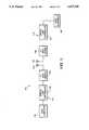
- FIG. 1is a simplified block diagram of an illustrative embodiment of the TDMA network of the present invention showing a vehicle transponder and a reader transponder.
- FIG. 2is a more detailed block diagram of the vehicle transponder shown in the TDMA network of FIG. 1 and illustrating a digital link controller and an RF modulation/demodulation section.
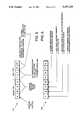
- FIG. 3is a graphical illustration of the protocol frame structure of the TDMA network of FIG. 1 showing adjacent frames N and N+1.
- FIGS. 4a, 4b, 4c and 4dare graphical illustrations of the standardized message formats utilized by network participants including a reader control message, a transponder identification message, a slot transmit/receive message and an acknowledgment message, respectively.
- FIG. 5is a more detailed graphical illustration of the type field present in each of the standardized message formats of FIGS. 4a, 4b, 4c and 4d.
- FIG. 6is a more detailed graphical illustration of the command field present in the reader control message of FIG. 4a.
- the inventionis embodied in a TDMA network 100 of the type used in reader-transponder communications having an RF modulation/demodulation section 102 for modulating, demodulating and converting signals between an analog and digital format and a digital link controller 104 for decoding messages and providing a protocol structure to the reader-transponder communications as shown in FIG. 1.
- a receive detector 106 and a transmit oscillator 108 of the RF modulation/demodulation section 102cooperate with a protocol logic device 110 of the digital link controller 104 shown in FIG. 2 to substantially simplify the process of identifying vehicles on a roadway and to eliminate restrictions on traffic flow.
- a protocol logic device 110 of the digital link controller 104 shown in FIG. 2to substantially simplify the process of identifying vehicles on a roadway and to eliminate restrictions on traffic flow.
- the inventionincludes a TDMA radio network which enables two-way data communications between the reader 112 and at least one vehicle transponder 114.
- the reader 112is usually a stationary transponder that can be positioned in any suitable location, for example, as part of the roadside infrastructure.
- the vehicle transponder 114is usually mobile and passes within the range of the reader 112 to permit interrogation and identification of the vehicle transponder 114.
- the term vehicleis intended to have wide application and can include, for example, a motorized unit such as an automobile, a truck, a ship or boat, a transported cargo container or the like.
- the reader 112would be mobile and the transponder 114 would be stationary.
- An example of such an applicationis one in which the transponder 114 is housed in a container stored in a warehouse and the reader 112 is a mobile hand operated transponder.
- the interrogation and identification of the container and its contentsis achieved by an individual carrying the reader 112.
- the reader 112is a stationary roadside transponder and the vehicle transponder 114 is housed within a mobile vehicle.
- the TDMA networkincludes a protocol that establishes the rules of communication.
- the protocolis designed for open road communication systems as opposed to single-lane communication systems.
- the advantage of open road communication systemsis that a single roadside reader 112 can interrogate and identify vehicles in several traffic lanes without traffic restrictions, lane barriers, overhead structures and the like as has been the case in the past. Therefore, the present invention is useful in many Intelligent Vehicle Highway Systems for applications such as electronic toll collection, route guidance (display), traveler information (broadcast), and commercial fleet tracking.
- FIG. 1A simplified block diagram of the TDMA network 100 which discloses the reader 112 and the vehicle transponder 114 is shown in FIG. 1.
- the reader 112 and the vehicle transponder 114each include a plurality of components which perform the same or similar functions. Therefore, those components of the reader 112 and vehicle transponder 114 which perform the same or similar functions will be described only once with any distinguishing features observed.
- the vehicle transponder 114includes an antenna 116, the RF modulation/demodulation section 102 and the digital link controller 104.
- An optional host computer 118is also shown.
- the reader 112includes an antenna 120, an RF modulation/demodulation section 122, a digital link controller 124 and host equipment 126.
- each antenna 116 and 120is utilized in a receive and transmit capacity.
- each antennafunctions to receive and convert radiated energy to a first RF voltage signal.
- each antennaserves to convert a second RF voltage signal to radiated energy.
- the RF modulator/demodulator sections 102 and 122serve to modulate the second RF voltage signal prior to being transmitted to the antennas 116 and 120, respectively.
- the digital link controllers 104 and 124each include the protocol structure of the present invention and serve to execute the timing and decision making logic instructions.
- the optional host computer 118 of the vehicle transponder 114serves several functions.
- the host computer 118can provide computer support and/or digital memory storage capacity to the protocol logic device 110 as shown in FIG. 2. Additionally, the host computer 118 can be employed to provide an interface to auxiliary devices (not shown) such as smart cards, digital displays or any data recording device. Further, the computer 118 can function to communicate with other computer peripherals such as the host equipment 126 shown connected to the digital link controller 124 of the reader 112 in FIG. 1. In such an arrangement, the vehicle transponder 114 and the reader 112 serve as modems to complete the communication link.
- the operation of the vehicle transponder 114will now be discussed with reference to FIG. 2.
- the radiated energyis received at the antenna 116 and converted to the first RF voltage signal.
- the first RF voltage signalis presented to a transmit/receive switch 130 located within the RF modulation/demodulation section 102.
- the switch 130routes the first RF voltage signal to the receive detector 106 in the receive path 132.
- the detector 106demodulates the amplitude modulated carrier wave of the first RF voltage signal to provide a demodulated baseband (Manchester) split-phase coded signal.
- the detectorprovides an analog-to-digital (A/D) conversion. If the magnitude of the first RF voltage signal exceeds a specified threshold, the output signal is a logical one. If the specified threshold is not exceeded, the output signal from the detector 106 is a logical zero.
- the detector 106can be, for example, an envelope detector.
- the demodulated baseband coded signalis then directed to a receive decoder 134 which converts the baseband signal to binary data bits. Further, the decoder 134 provides clock synchronization to the protocol logic device 110. The binary data bits, which form a message received from the reader 112, are then directed to the protocol logic device 110. The protocol logic device 110 decodes the binary data bits and executes the protocol structure which controls the timing and decision making logic instructions of the digital link controller 104. Examples of the decision making logic instructions include timing, message slot selection, memory input/output and transmit/receive control. A detailed discussion of the protocol structure of the present invention appears below in conjunction with FIGS. 4-6.
- the protocol logic device 110is shown in two-way communication with the host computer 118 in FIG. 2.
- the host computerprovides computer support and/or memory storage capacity to the protocol logic device 110 and serves as an interface to computer peripheral equipment.
- the protocol logic device 110is also connected to a plurality of indicators 136 mounted on the vehicle transponder 114.
- the purpose of the indicators 136is to signal the operator of the vehicle transponder 114 to perform some function, for example, to direct the vehicle to the roadway weigh station.
- the physical embodiment of the indicators 136can include light emitting diodes, audio tones and the like.
- the memory 138is connected at the end of the receive path 132 within the digital link controller 104.
- the memory 138provides long term storage of standard data for identifying the vehicle transponder 114 upon interrogation of the reader 112. Examples of the data stored in the memory 138 can include the vehicle type, registration number, vehicle identification number, operator identification and license number, vehicle weight, maximum load weight capacity, cargo information such as the bill of lading, ports of entry and the like.
- data provided by the host computer 118 or the memory 138is formatted in the protocol logic device 110.
- the formatting procedureis in accordance with the protocol structure of the present invention.
- the protocol formatted digital datais then directed to the transmit oscillator 108 in the transmit path 140.
- the formatted digital datais utilized to modulate a transmit oscillator carrier wave to convert the data from a digital-to-analog (D/A) format.
- the output signal of the transmit oscillator 108is the second (amplitude modulated) RF voltage signal.
- the second RF voltage signalis then directed to a transmit power amplifier 142 which boosts the signal level thereof.
- the second RF voltage signalis then transmitted to the transmit/receive switch 130.
- the transmit/receive switch 130which is controlled by the protocol structure, routes the second RF voltage signal to the antenna 116.
- the antenna 116then converts the second RF voltage signal to radiated energy which is thereafter transmitted to the reader 112.
- the structural combination and operation of the reader 112is very similar to that of the vehicle transponder 114 shown in FIG. 2. Only a few minor variations exist between the reader 112 and the transponder 114. Those variations include the absence of the indicators 136 and the memory 138 in the reader 112. The indicators 136 are not necessary since the reader 112 is not attended by an operator. Further, since the reader 112 performs the interrogation function on the vehicle transponder 114, a need for a depository of identification information in the reader 112 does not exist.
- the reader 112is the functional equivalent to the vehicle transponder 114 except that the corresponding element for the protocol logic device 110 in the reader 112 executes the portion of the protocol structure associated with the reader 112.
- the protocol structure of the reader 112is directed to the interrogation and control functions. Examples of the protocol structure of the reader 112 include generation of a reader control message each frame and assignment of message slots as will be discussed hereinbelow.
- the protocol structure associated with the protocol logic device 110 shown in FIG. 2will now be discussed.
- the network protocolemploys a time division multiple access (TDMA) scheme in which various users are assigned specific time intervals in which to communicate. By taking turns, many users can share a single frequency channel.
- TDMAtime division multiple access
- the present inventioneliminates the need to isolate users, either physically or by using separate frequency assignments, to keep their respective communications from interfering with one another.
- the protocol structure of the present inventionis illustrated in FIGS. 3-6.
- the pure slotted aloha scheme based upon random selectionbecomes undesirable when the traffic density increases.
- the fixed slot assignment schemeis very inefficient when slots are reserved for a large number of potentially infrequent users.
- a novel approachlies in the unique combination of slotted aloha and fixed slot protocols.
- the slotted aloha protocolprovides random slots which are used as a means for vehicle transponders 114 to enter the TDMA communication network 100.
- the slotted aloha random slotsare not used for communication of data.
- the transponder 114is assigned specific and unique time slots. Thereafter, data communication occurs between the reader 112 and the vehicle transponder 114 in the assigned time slots. Entry of a vehicle transponder 114 to the TDMA network 100 is not permitted during the assigned time slots.
- This protocol ruleeliminates interference between response signals of different vehicle transponders 114 and ensures a very high data communication success rate between the reader 112 and the transponders 114. Further, an increased number of transponders 114 can be accommodated by the TDMA network 100 since message repeat time is minimized. This combination of time slots provides the best results for the following reasons.
- the random time slot selectionis convenient for entry into the TDMA network 100 but is a poor choice for uniquely communicating with a large number of vehicle transponders 114.
- the assigned time slotsare efficient for communicating among a known list of vehicle transponders 114 but entry into the TDMA network 100 by vehicle transponders 114 is difficult.
- the protocol of the TDMA network 100is optimized for short range, high data rate burst communications.
- the network 100is optimized for non-continuous data communications within 100' at a rate of, for example, 500 Kbits/sec.
- Timeis divided into repetitive frames 150 with each frame 150 containing two types of slots used by all network participants (e.g., vehicle transponders 114) as shown in FIG. 3.
- a different method of assignmentis used for each type of time slot and protocol discipline is maintained by the reader 112.
- the first type of time slotis an activation slot 152 which is utilized by the vehicle transponders 114 to gain entry to the TDMA network 100.
- the vehicle transponders 114select an activation time slot 152 at random and successfully contact the reader 112 if another vehicle transponder 114 does not select the same activation slot 152. Thereafter, the reader 112 assigns a message slot 154 to vehicle transponders 114 that have transmitted an identification message to the reader 112 and that identification message has been recognized.
- the message slots 154are utilized for the transfer of data between the vehicle transponders 114 and the reader 112.
- the protocolreserves the message slot time to the particular vehicle transponder 114 to which the message slot 154 was assigned.
- the reader 112functions as a control unit and establishes the basic timing for the protocol. Time is divided into ten millisecond (10 msec) frames 150 which provides one-hundred frames per second. The protocol is represented by two adjacent frames 150 labeled N and N+1 in FIG. 3. At the beginning of each frame 150, the reader 112 transmits a reader control message 156 to the vehicle transponders 114.
- the reader control message 156 shown in FIG. 4acontains information relating to the assignment of message time slots 154 to vehicle transponders 114.
- the reader control message 156also provides a timing reference from which all vehicle transponders 114 compute elapsed time.
- the remainder of the frame 150is divided into the message slots 154 which are assigned to specific vehicle transponders 114 and activation slots 152 which can be employed by any vehicle transponder 114 attempting to gain entry to the TDMA network 100.
- each message slot 154is bi-directional so that a message can be sent in either direction between the reader 112 and the vehicle transponder 114.
- a small acknowledge message time slot 158is located within each message slot 154.
- the acknowledge message time slot 158 shown in FIG. 4dis utilized by the receiving transponder to signal the transmitting transponder of a successful reception of the message. Therefore, link validation and positive acknowledgement of data transactions is provided.
- a mobile vehicle transponder 114comes within range (e.g., enters the field) of the roadside reader 112.
- the reader 112transmits and the vehicle transponder 114 receives a 224-bit reader control message 156 indicating the beginning of the frame 150 labeled N.
- the vehicle transponder 114waits a period of time equal to the time allocated to the four message slots 154.
- the frame 150has advanced to the beginning of the activation time slots 152.
- the vehicle transponder 114randomly selects one of the sixteen activation time slots 152 and transmits a short transponder identification message 160 shown in FIG. 4b to the reader 112.
- the transponder identification message 160contains a unique identification number used to gain access to the TDMA network 100.
- the unique transponder identification numberis stored in the memory 138 of the vehicle transponder shown in FIG. 2.
- the reader control message 156 of the next frame 150 labeled N+1is monitored by the vehicle transponder 114.
- the purpose of the monitoringis to determine if the unique identification number of that transponder 114 appears among the identification numbers listed. If that unique identification number is listed in the reader control message 156 of frame N+1, then authorization is granted to use the corresponding message time slot 154 to transmit or receive a message.
- the vehicle transponder 114is shown utilizing message slot 164 labeled 83 in FIG. 3.
- the transponder 114has not been assigned a message time slot 154. Examples of reasons why a message time slot 154 might not be assigned include the reader 112 did not receive the identification message 160 and identification number from the transponder 114, another transponder user selected the same activation time slot 152, a queue of more than four transponders 114 is awaiting the assignment of message slots 154, or the reader control message 156 was not clearly received by the transponder 114. Under these conditions, the transponder 114 selects another random time slot in the next activation slot 152, transmits another identification message 160 and repeats the procedure until a message slot 154 is assigned.
- an eight-bit command field 162 in the reader control message 156 shown in FIG. 4aindicates to the vehicle transponder 114 whether it will transmit or receive the message.
- Either the reader 112 or the vehicle transponder 114utilizes a slot TX/RX message 164 shown in FIG. 4c to communicate up to five-hundred twelve message bits of data.
- the transponder receiving the messageemploys a positive acknowledge (Ack) message 158 shown in FIG. 4d to signal a successful reception to the transmitting transponder. If the slot TX/RX message 164 is not received correctly, a negative acknowledge (Ack) message is sent to the transmitting transponder.
- Ackpositive acknowledge
- the reader 112If the reader 112 does not receive an acknowledge message 158 following a transmission made to a vehicle transponder 114, the reader 112 provides another opportunity to the transponder 114. This is achieved by the reader 112 scheduling another message slot 154 for that transponder 114. If a vehicle transponder 114 transmits a message to the reader 112 and fails to receive an acknowledge message 158, the transponder 114 attempts to contact the reader 112. Initially, the transponder 114 seeks another message slot 154 to contact the reader 112. If another message slot 154 is not available, the transponder 114 attempts to contact the reader 112 through the entry process by utilizing the activation slots 152.
- Message validityis provided by a cyclical redundancy code (CRC) checksum known in the art which is part of each message type.
- the message typesinclude the reader control message 156, the transponder identification message 160, the slot TX/RX/ message 164 and the acknowledge message 158.
- the checksumis computed using all the message fields except a header field 166 and a CRC field 168.
- a shift register with feedback taps(not shown) and an algorithm are used.
- An example of an algorithm suitable for use in data validity checksis a communications industry standard known as the CRC-16 algorithm.
- the last sixteen data bits clocked out of the shift registeris the checksum.
- the checksumis then appended to the message by the transmitting transponder.
- the receiving transpondercomputes the checksum and compares it against the transmitted checksum. Any bit errors will cause the checksums to disagree. This procedure provides a reliable means of detecting faulty messages.
- a sixty-four bit seed field 170is formed as part of the reader control message 156 shown in FIG. 4a.
- the reader 112places a different value in the seed field 170 in each frame 150.
- Vehicle transponders 114 with slot assignments in that frame 150will use the seed value in the seed field 170 as the starting point in the anti-counterfeiting algorithm.
- the algorithmis employed to compute a checksum using the message data.
- Two examples of algorithms known in the art and suitable for use as the anti-counterfeiting algorithminclude the Data Encryption Standard (DES) algorithm and the Riest, Shamir & Adleman (RSA) algorithm.
- DESData Encryption Standard
- RSAShamir & Adleman
- the checksumis included in a valid field 172 located in the slot TX/RX message 164 shown in FIG. 4c.
- the reader 112can compute the checksum based upon the seed value in the seed field 170 and the received message data.
- the checksum computed by the reader 112is then verified against the valid field 172 in the slot TX/RX message 164.
- the CRC algorithm utilized to verify error free transmissiondoes not offer anti-counterfeiting protection. Since the value of the seed field 170 is changed each frame 150, a message from a previous frame 150 will be detected and rejected by the anti-counterfeiting algorithm. This is the case since the seed value from a previous frame 150 will generate a different valid field 172 from that generated by the seed of the current frame 150. Additional message integrity schemes which disguise the actual message data through encryption are anticipated, particularly in the transmission of financial data.
- bit fields shown in FIG. 4include a thirty-two bit identification field 161 which is illustrated in both the reader control message 156 of FIG. 4a and the transponder identification message 160 of FIG. 4b.
- the bit identification field 161includes identification information transmitted from the vehicle transponder 114 to the reader 112 during interrogation of the transponder 114.
- a four bit sleep field 163 and a four bit spare field 165are each included as shown in FIG. 4a.
- the TDMA network 100 of the present inventionis electronic toll collection.
- the TDMA protocolhas been designed not to require new message types to support other applications beyond the specific example provided.
- the type field 174indicates both the reader type and the message type. Referring to FIG. 5, it is noted that the reader type and the message type each include four blocks. Each slot is identified by a code letter. In identifying the reader type, each block includes either a "V" or an "R" code letter. If the numeral "1" appears in the "V" block, the protocol of the TDMA network 100 is being utilized. The code letter "R" appearing in the remaining three bits are reserved for a numeral which indicates another reader type.
- two blocksinclude a "T" code letter and the two remaining blocks include “ST” code letters.
- Four binary combinations of "0" and “1”can appear in the two bits labeled "T”.
- the combination "00”indicates that the message is a transponder identification message 160 and the combination "01” indicates that the message is a slot TX/RX message 164.
- the combination "10”indicates an acknowledge message 158 and the combination "11” indicates a reader control message 156.
- the remaining two bits which have the code letters "ST”indicate a message type subcode which uses one of four character combinations.
- the message type subcode "01”indicates a positive acknowledge message or "Ack” while the subcode “00” indicates a negative acknowledge message or "Nack”.
- the message type subcode "X0”indicates low transponder battery power while the subcode “X1” indicates that the transponder battery power is not of concern (e.g., the "X” indicates a "don't care”).
- the TDMA network 100normally employs a roadside reader 112, however, other types of readers can be implemented. Restrictions are not placed upon the implementation of other protocols in order to enjoy the advantages of the TDMA structure of the present invention.
- the reader control message 156will indicate the specific protocol employed and the initiation of the time of the frame 150.
- Vehicle transponders 114can identify the exact protocol variation and participate in the communication, if desired.
- the present inventioncan be utilized to support a variety of specific intelligent vehicle highway system applications while employing a common set of equipment comprising vehicle transponders 114 and a reader 112.
- the command field 162 in the reader control message 156can be expanded as shown in FIG. 6.
- the command field 162includes eight bits identified by code letters.
- the reader 112can instruct the vehicle transponder 114 to transmit or receive a message.
- a "1" located in the "T” bitinstructs the transponder 114 to transmit a message to the reader 112 while a "0" in the "T” bit instructs the transponder 114 to receive a message from the reader 112.
- the reader 112can place the transponder 114 in a broadcast mode where the message is intended for all the vehicle transponders 114.
- a "1" in the "B" bit of the command field 162places all the transponders 114 in the broadcast receive mode where all four bits are used and an acknowledge message 158 is not required.
- a "0" in the "B” bitindicates that the broadcast receive mode is not activated.
- a message having too many characters to fit into a single message slot 154 shown in FIG. 3can be transmitted in multiple slots.
- the use of multiple slots for a single messagecan be indicated by placing a "0" in the "C" bit of the command field 162 as shown in FIG. 6. This code indicates that there is more message to follow.
- a specific vehicle transponder 114can be assigned all four message slots 154 in a single frame 150 or be assigned message slots 154 in different frames. If a "1" is placed in the "C" bit, the indication is that this frame 150 is the last frame of the message, e.g., the message is complete. Finally, the message can be intended for internal use only, such as in reprogramming parameters in the vehicle transponder 114.
- An internal memory messageis indicated by placing a "0" in the "M” bit of the command field 162.
- the messagecan also be intended for external use such as when a vehicle transponder 114 passes a message to a human operator or a display screen used in a vehicle navigation system. Under these conditions, a "1" is placed in the "M” bit of the command field 162.
- the remainder of the bits in the command field 162 shown in FIG. 6are labeled "R" which indicates that those bits are reserved for other uses.
- the data rateis currently 500 Kbits/sec. Since the data rate, message length and frame rate are interdependent, the TDMA protocol can be operated at any desired data rate and frame rate. Further, the TDMA protocol is not radio frequency or modulation dependent.
- the present inventionemploys a protocol structure within a TDMA network 100 which permits two-way communication of one or more five-hundred twelve bit packages in each direction between a reader 112 and at least one vehicle transponder 114.
- the inventionsimplifies the process of identifying vehicles on a roadway and permits every vehicle on the roadway to be identified by eliminating destructive interference of simultaneous response signals. These advantages are achieved by obviating the requirement of a per-lane antenna which reduces network infrastructure.
- the protocol structureis designed to operate efficiently with vehicles traveling at one-hundred mph and spaced as closely as ten feet apart. By removing speed and lane restrictions, the invention reduces the impact to traffic flow and improves the reliability of the network under conditions of lane straddling.
- Two vehicles in a lane, such as motorcycles,can be reliably detected.
- the inventionalso exhibits improved flexibility for extending the message structure and protocol to additional applications such as read-only, read-write and broadcast modes. These additional applications can be implemented using the protocol of the present invention.
- a single vehicle transponder 114can be used in a wide range of applications from toll collection (read-only) to commercial debit transactions (read-write) to highway advisory announcements (broadcast).
Landscapes
- Engineering & Computer Science (AREA)
- Computer Networks & Wireless Communication (AREA)
- Signal Processing (AREA)
- Mobile Radio Communication Systems (AREA)
- Traffic Control Systems (AREA)
- Time-Division Multiplex Systems (AREA)
Abstract
Description
Claims (11)
Priority Applications (6)
| Application Number | Priority Date | Filing Date | Title |
|---|---|---|---|
| US07/864,703US5307349A (en) | 1992-04-07 | 1992-04-07 | TDMA network and protocol for reader-transponder communications and method |
| IL10528093AIL105280A (en) | 1992-04-07 | 1993-04-02 | TDMA network and protocol for reader-transponder communications |
| KR1019930005678AKR960000931B1 (en) | 1992-04-07 | 1993-04-06 | Tdma network and protocol for reader-transponder |
| EP93105675AEP0565046A3 (en) | 1992-04-07 | 1993-04-06 | Tdma network and protocol for reader-transponder communications and method |
| JP5080987AJPH07123318B2 (en) | 1992-04-07 | 1993-04-07 | Method for providing TDMA network protocol configuration for reader-transponder communication |
| US08/194,674US5425032A (en) | 1992-04-07 | 1994-02-10 | TDMA network and protocol for reader-transponder communications and method |
Applications Claiming Priority (1)
| Application Number | Priority Date | Filing Date | Title |
|---|---|---|---|
| US07/864,703US5307349A (en) | 1992-04-07 | 1992-04-07 | TDMA network and protocol for reader-transponder communications and method |
Related Child Applications (1)
| Application Number | Title | Priority Date | Filing Date |
|---|---|---|---|
| US08/194,674DivisionUS5425032A (en) | 1992-04-07 | 1994-02-10 | TDMA network and protocol for reader-transponder communications and method |
Publications (1)
| Publication Number | Publication Date |
|---|---|
| US5307349Atrue US5307349A (en) | 1994-04-26 |
Family
ID=25343872
Family Applications (2)
| Application Number | Title | Priority Date | Filing Date |
|---|---|---|---|
| US07/864,703Expired - LifetimeUS5307349A (en) | 1992-04-07 | 1992-04-07 | TDMA network and protocol for reader-transponder communications and method |
| US08/194,674Expired - Fee RelatedUS5425032A (en) | 1992-04-07 | 1994-02-10 | TDMA network and protocol for reader-transponder communications and method |
Family Applications After (1)
| Application Number | Title | Priority Date | Filing Date |
|---|---|---|---|
| US08/194,674Expired - Fee RelatedUS5425032A (en) | 1992-04-07 | 1994-02-10 | TDMA network and protocol for reader-transponder communications and method |
Country Status (5)
| Country | Link |
|---|---|
| US (2) | US5307349A (en) |
| EP (1) | EP0565046A3 (en) |
| JP (1) | JPH07123318B2 (en) |
| KR (1) | KR960000931B1 (en) |
| IL (1) | IL105280A (en) |
Cited By (97)
| Publication number | Priority date | Publication date | Assignee | Title |
|---|---|---|---|---|
| US5424727A (en)* | 1994-03-22 | 1995-06-13 | Best Network Systems, Inc. | Method and system for two-way packet radio-based electronic toll collection |
| US5440559A (en)* | 1993-11-10 | 1995-08-08 | Seiko Communications Holding N.V. | Portable wireless communication device |
| EP0715185A2 (en) | 1994-11-30 | 1996-06-05 | Hughes Aircraft Company | Transponder detection system and method |
| US5535210A (en)* | 1994-07-29 | 1996-07-09 | Motorola, Inc. | Method and system for resolution of channel access in data transmission systems |
| US5544075A (en)* | 1993-07-20 | 1996-08-06 | Thomson-Csf | Method to optimize the bit rate of a communications channel in time-division mode |
| US5554982A (en)* | 1994-08-01 | 1996-09-10 | Hughes Aircraft Co. | Wireless train proximity alert system |
| WO1997013208A1 (en)* | 1995-10-06 | 1997-04-10 | Scientific-Atlanta, Inc. | Electronic vehicle log |
| US5640687A (en)* | 1993-05-24 | 1997-06-17 | Tadiran Ltd. | Backscattering transponder switchable between a modulator/demodulator and ground |
| US5697097A (en)* | 1993-09-09 | 1997-12-09 | Rds Technologies | Method for increasing the endurance of an information receiver, particularly for radio paging, and corresponding receiver |
| US5706278A (en)* | 1995-07-20 | 1998-01-06 | Raytheon Company | Deterministic network protocol |
| US5751227A (en)* | 1994-12-22 | 1998-05-12 | Nippondenso Co., Ltd. | Communication system for vehicles |
| US5761197A (en)* | 1994-11-14 | 1998-06-02 | Northern Telecom Limited | Communications in a distribution network |
| US5796935A (en)* | 1995-07-20 | 1998-08-18 | Raytheon Company | Voting node for a distributed control system |
| US5809220A (en)* | 1995-07-20 | 1998-09-15 | Raytheon Company | Fault tolerant distributed control system |
| US5828333A (en)* | 1997-01-21 | 1998-10-27 | Northrop Grumman Corporation | Multiple access diplex doppler radar |
| US6052365A (en)* | 1995-06-02 | 2000-04-18 | Dsc Communications Corporation | Multi-channel digital data transmission in a wireless telecommunications system |
| US6088659A (en)* | 1997-09-11 | 2000-07-11 | Abb Power T&D Company Inc. | Automated meter reading system |
| US20010039537A1 (en)* | 1997-02-12 | 2001-11-08 | Carpenter Richard Christopher | Network-enabled, extensible metering system |
| US20020023249A1 (en)* | 2000-08-15 | 2002-02-21 | Lockheed Martin Corporation | Method and apparatus for reliable unidirectional communication in a data network |
| US6351640B1 (en) | 1995-12-15 | 2002-02-26 | Lucent Technologies, Inc. | Initiating a Telecommunications call to a party based on an identifying signal wirelessly transmitted by the party or its proxy |
| US20020063622A1 (en)* | 2000-11-29 | 2002-05-30 | Ludwig Kipp | Method and system for communicating with and tracking RFID transponders |
| US20020075891A1 (en)* | 2000-12-16 | 2002-06-20 | Slim Souissi | Network assisted random access method |
| US20030020993A1 (en)* | 2000-08-15 | 2003-01-30 | Lockheed Martin Corporation | Method and system for infrared data communications |
| US20030128100A1 (en)* | 2001-11-26 | 2003-07-10 | Aero-Vision Technologies, Inc. | System and method for monitoring individuals and objects associated with wireless identification tags |
| US20030137967A1 (en)* | 2001-12-17 | 2003-07-24 | Erez Geva | Method and apparatus for bandwidth reservations |
| US20040001008A1 (en)* | 2002-06-27 | 2004-01-01 | Shuey Kenneth C. | Dynamic self-configuring metering network |
| US6700902B1 (en) | 1998-10-19 | 2004-03-02 | Elster Electricity, Llc | Method and system for improving wireless data packet delivery |
| US20040114566A1 (en)* | 2002-12-16 | 2004-06-17 | Hyoung-Soo Lim | Error control method, medium access control (MAC) frame designing method, and terminal registration method in wireless communication system, and recording medium |
| US20040140884A1 (en)* | 1999-10-27 | 2004-07-22 | Microchip Technology Inc. | Anticollision protocol with fast read request and additional schemes for reading multiple transponders in an RFID system |
| US20040160310A1 (en)* | 2003-02-14 | 2004-08-19 | Mao-Song Chen | Radio frequency identification device |
| US20040198222A1 (en)* | 2002-10-02 | 2004-10-07 | Emre Ertin | Method of simultaneously reading multiple radio frequency tags, RF tags, and RF reader |
| US20040218616A1 (en)* | 1997-02-12 | 2004-11-04 | Elster Electricity, Llc | Remote access to electronic meters using a TCP/IP protocol suite |
| US20050024186A1 (en)* | 2003-08-01 | 2005-02-03 | Atmel Germany Gmbh | Method for selecting one or more transponders |
| US6867707B1 (en) | 2002-04-24 | 2005-03-15 | Elster Electricity, Llc | Automated on-site meter registration confirmation using a portable, wireless computing device |
| US20050111682A1 (en)* | 2003-11-26 | 2005-05-26 | Starkey Laboratories Inc. | Transmit-receive switching in wireless hearing aids |
| US6917281B1 (en)* | 2000-07-07 | 2005-07-12 | Motorola, Inc. | Method and apparatus for transmitting and decoding pre-programmed messages |
| US20050207446A1 (en)* | 2004-03-17 | 2005-09-22 | Zion Hadad | Synchronization system and method |
| US20050206366A1 (en)* | 2004-03-18 | 2005-09-22 | Shuey Kenneth C | Bias technique for electric utility meter |
| US20050206365A1 (en)* | 2004-03-18 | 2005-09-22 | Shuey Kenneth C | Reducing power consumption of electrical meters |
| US20050237221A1 (en)* | 2004-04-26 | 2005-10-27 | Brian Brent R | System and method for improved transmission of meter data |
| US20050240540A1 (en)* | 2004-04-26 | 2005-10-27 | Borleske Andrew J | System and method for efficient configuration in a fixed network automated meter reading system |
| US20050239414A1 (en)* | 2004-04-26 | 2005-10-27 | Mason Robert T Jr | Method and system for configurable qualification and registration in a fixed network automated meter reading system |
| US20050251401A1 (en)* | 2004-05-10 | 2005-11-10 | Elster Electricity, Llc. | Mesh AMR network interconnecting to mesh Wi-Fi network |
| US20050251403A1 (en)* | 2004-05-10 | 2005-11-10 | Elster Electricity, Llc. | Mesh AMR network interconnecting to TCP/IP wireless mesh network |
| US20050278440A1 (en)* | 2004-06-15 | 2005-12-15 | Elster Electricity, Llc. | System and method of visualizing network layout and performance characteristics in a wireless network |
| US20060023629A1 (en)* | 2004-07-16 | 2006-02-02 | Samsung Electronics Co., Ltd. | Method and apparatus for performing autonomous transmission in a mobile communication system for supporting an enhanced uplink dedicated channel |
| US20060069661A1 (en)* | 2004-09-24 | 2006-03-30 | Scoggins Sean M | System and method for automated configuration of meters |
| US20060071811A1 (en)* | 2004-09-24 | 2006-04-06 | Christopher Russell G | System and method for creating multiple operating territories within a meter reading system |
| US20060071812A1 (en)* | 2002-06-28 | 2006-04-06 | Elster Electricity Llc | Data collector for an automated meter reading system |
| US20060072465A1 (en)* | 2004-09-24 | 2006-04-06 | Scoggins Sean M | System for automated management of spontaneous node migration in a distributed fixed wireless network |
| US20060071810A1 (en)* | 2004-09-24 | 2006-04-06 | Elster Electricity, Llc. | System for automatically enforcing a demand reset in a fixed network of electricity meters |
| US20060125605A1 (en)* | 2004-12-13 | 2006-06-15 | Atmel Germany Gmbh | Method for locating a backscatter-based transponder |
| US20060135119A1 (en)* | 2004-12-22 | 2006-06-22 | Navaneet Kumar | System and method of providing a geographic view of nodes in a wireless network |
| US20060164213A1 (en)* | 2005-01-26 | 2006-07-27 | Battelle Memorial Institute | Method for autonomous establishment and utilization of an active-RF tag network |
| US20060202801A1 (en)* | 2001-02-21 | 2006-09-14 | At&T Corp. | Location system and communication |
| US20060206433A1 (en)* | 2005-03-11 | 2006-09-14 | Elster Electricity, Llc. | Secure and authenticated delivery of data from an automated meter reading system |
| US20060224335A1 (en)* | 2005-03-29 | 2006-10-05 | Elster Electricity, Llc | Collecting interval data from a relative time battery powered automated meter reading devices |
| US20060256798A1 (en)* | 2003-08-08 | 2006-11-16 | Clipsal Integrated Systems Pty Ltd. | Radio network communication system and protocol |
| US20070063868A1 (en)* | 2005-09-02 | 2007-03-22 | Elster Electricity, Llc | Multipurpose interface for an automated meter reading device |
| US20070073866A1 (en)* | 2005-09-28 | 2007-03-29 | Elster Electricity, Llc | Ensuring automatic season change demand resets in a mesh type network of telemetry devices |
| US20070147268A1 (en)* | 2005-12-23 | 2007-06-28 | Elster Electricity, Llc | Distributing overall control of mesh AMR LAN networks to WAN interconnected collectors |
| US20070159301A1 (en)* | 2006-01-06 | 2007-07-12 | Hirt Fred S | Dynamic cell size variation via wireless link parameter adjustment |
| US20070200729A1 (en)* | 2006-02-16 | 2007-08-30 | Elster Electricity, Llc | In-home display that communicates with a fixed network meter reading system |
| US20070205915A1 (en)* | 2006-02-16 | 2007-09-06 | Elster Electricty, Llc | Load control unit in communication with a fixed network meter reading system |
| US7308370B2 (en) | 2005-03-22 | 2007-12-11 | Elster Electricity Llc | Using a fixed network wireless data collection system to improve utility responsiveness to power outages |
| US7312692B2 (en)* | 2003-10-21 | 2007-12-25 | Atmel Germany Gmbh | Method for selecting one or several transponders |
| US20080048836A1 (en)* | 2006-08-22 | 2008-02-28 | Bungartz Joern | Electromedical implant |
| US20080088414A1 (en)* | 2004-07-29 | 2008-04-17 | Hiroyoshi Suga | Radio-Tag Reading System, Radio-Tag Reader, And Radio Tag |
| US20080144548A1 (en)* | 2006-12-14 | 2008-06-19 | Elster Electricity, Llc | Optimization of redundancy and throughput in an automated meter data collection system using a wireless network |
| US20080204194A1 (en)* | 2005-04-15 | 2008-08-28 | Nxp B.V. | Rfid Transponder |
| US20080259844A1 (en)* | 2007-04-20 | 2008-10-23 | Elster Electricity, Llc | Over the air microcontroller flash memory updates |
| WO2007133264A3 (en)* | 2005-12-09 | 2009-03-05 | Automotive Comm Systems Inc | Integrated vehicular positioning and communications system |
| US7501954B1 (en)* | 2000-10-11 | 2009-03-10 | Avante International Technology, Inc. | Dual circuit RF identification tags |
| US20090134975A1 (en)* | 2007-11-23 | 2009-05-28 | Sungkyunkwan University Foundation For Corporate Collaboration | Tag estimation method and tag identification method for rfid system |
| US20090219142A1 (en)* | 2008-02-29 | 2009-09-03 | Ku Ja-Nam | Rfid system and method of transmitting large data of passive rfid |
| US20090231161A1 (en)* | 2008-03-11 | 2009-09-17 | Alastair Malarky | Real-time vehicle position determination using communications with variable latency |
| US20090309756A1 (en)* | 2008-06-13 | 2009-12-17 | Elster Electricity, Llc | Techniques For Limiting Demand From An electricity Meter With An Installed Relay |
| US20090322479A1 (en)* | 2007-05-23 | 2009-12-31 | Sony Corporation | Communications system and communications apparatus |
| US20100039237A1 (en)* | 2008-06-26 | 2010-02-18 | Sridhar Radhakrishnan | Framework for fast rfid tag reading in static and mobile environments |
| US8203463B2 (en) | 2009-02-13 | 2012-06-19 | Elster Electricity Llc | Wakeup and interrogation of meter-reading devices using licensed narrowband and unlicensed wideband radio communication |
| US9612132B2 (en) | 2007-12-26 | 2017-04-04 | Elster Solutions, Llc | Optimized data collection in a wireless fixed network metering system |
| US20200066313A1 (en)* | 2018-08-21 | 2020-02-27 | Marcon International Inc Dba Keyper Systems | Circuit, system, and method for reading memory-based digital identification devices in parallel |
| US10698989B2 (en) | 2004-12-20 | 2020-06-30 | Proxense, Llc | Biometric personal data key (PDK) authentication |
| US10764044B1 (en) | 2006-05-05 | 2020-09-01 | Proxense, Llc | Personal digital key initialization and registration for secure transactions |
| US10769939B2 (en) | 2007-11-09 | 2020-09-08 | Proxense, Llc | Proximity-sensor supporting multiple application services |
| US10909229B2 (en) | 2013-05-10 | 2021-02-02 | Proxense, Llc | Secure element as a digital pocket |
| US10943471B1 (en) | 2006-11-13 | 2021-03-09 | Proxense, Llc | Biometric authentication using proximity and secure information on a user device |
| US10971251B1 (en) | 2008-02-14 | 2021-04-06 | Proxense, Llc | Proximity-based healthcare management system with automatic access to private information |
| US11080378B1 (en) | 2007-12-06 | 2021-08-03 | Proxense, Llc | Hybrid device having a personal digital key and receiver-decoder circuit and methods of use |
| US11086979B1 (en) | 2007-12-19 | 2021-08-10 | Proxense, Llc | Security system and method for controlling access to computing resources |
| US11095640B1 (en) | 2010-03-15 | 2021-08-17 | Proxense, Llc | Proximity-based system for automatic application or data access and item tracking |
| US11113482B1 (en) | 2011-02-21 | 2021-09-07 | Proxense, Llc | Implementation of a proximity-based system for object tracking and automatic application initialization |
| US11120449B2 (en) | 2008-04-08 | 2021-09-14 | Proxense, Llc | Automated service-based order processing |
| US11206664B2 (en) | 2006-01-06 | 2021-12-21 | Proxense, Llc | Wireless network synchronization of cells and client devices on a network |
| US11258791B2 (en) | 2004-03-08 | 2022-02-22 | Proxense, Llc | Linked account system using personal digital key (PDK-LAS) |
| US11546325B2 (en) | 2010-07-15 | 2023-01-03 | Proxense, Llc | Proximity-based system for object tracking |
| US12446014B2 (en) | 2023-09-06 | 2025-10-14 | Proxense, Llc | Wireless network synchronization of cells and client devices on a network |
Families Citing this family (60)
| Publication number | Priority date | Publication date | Assignee | Title |
|---|---|---|---|---|
| JP3421378B2 (en)* | 1993-03-23 | 2003-06-30 | 株式会社東芝 | Transmission control method |
| US5506584A (en)* | 1995-02-15 | 1996-04-09 | Northrop Grumman Corporation | Radar sensor/processor for intelligent vehicle highway systems |
| US5633875A (en)* | 1995-06-07 | 1997-05-27 | General Electric Company | Protocol and mechanism for centralized asset tracking communications |
| US5745049A (en)* | 1995-07-20 | 1998-04-28 | Yokogawa Electric Corporation | Wireless equipment diagnosis system |
| US5940006A (en)* | 1995-12-12 | 1999-08-17 | Lucent Technologies Inc. | Enhanced uplink modulated backscatter system |
| US5809243A (en)* | 1995-12-29 | 1998-09-15 | Lsi Logi Corporation | Personal interface system for wireless and wired communications |
| US5822683A (en)* | 1996-04-05 | 1998-10-13 | Ball Aerospace And Technologies Corp. | Pseudo-passive transponder device |
| US6046683A (en)* | 1996-12-31 | 2000-04-04 | Lucent Technologies Inc. | Modulated backscatter location system |
| US6456668B1 (en) | 1996-12-31 | 2002-09-24 | Lucent Technologies Inc. | QPSK modulated backscatter system |
| EP0898815B1 (en)* | 1997-01-21 | 2005-09-28 | Koninklijke Philips Electronics N.V. | Transponder communications device |
| DE69829819T2 (en)* | 1997-01-21 | 2006-05-11 | Koninklijke Philips Electronics N.V. | TRANSPONDER COMMUNICATIONS DEVICE |
| US6570487B1 (en) | 1997-01-24 | 2003-05-27 | Axcess Inc. | Distributed tag reader system and method |
| US6034603A (en)* | 1997-01-24 | 2000-03-07 | Axcess, Inc. | Radio tag system and method with improved tag interference avoidance |
| JPH10257005A (en) | 1997-03-12 | 1998-09-25 | Sony Corp | Communication method, transmitter and receiver |
| JP3808620B2 (en)* | 1997-03-21 | 2006-08-16 | 株式会社東芝 | Information identification system, control device and response device for the information identification system |
| JPH11205264A (en) | 1998-01-19 | 1999-07-30 | Nec Corp | Multi-direction time division multiplexed radio data communication system |
| FR2785423B1 (en)* | 1998-10-30 | 2001-01-12 | St Microelectronics Sa | IMPROVEMENT IN METHODS FOR IDENTIFYING ELECTRONIC CARDS |
| US6294953B1 (en) | 1999-02-26 | 2001-09-25 | Axcess, Inc. | High sensitivity demodulator for a radio tag and method |
| US7005985B1 (en) | 1999-07-20 | 2006-02-28 | Axcess, Inc. | Radio frequency identification system and method |
| CA2381362C (en)* | 1999-08-11 | 2013-08-06 | Mark Iv Industries Limited | Method and means for rf toll collection |
| ATE386309T1 (en)* | 1999-09-22 | 2008-03-15 | Em Microelectronic Marin Sa | TRANSPONDER FOR DIFFERENT PURPOSES |
| US7286158B1 (en) | 1999-12-22 | 2007-10-23 | Axcess International Inc. | Method and system for providing integrated remote monitoring services |
| US6369710B1 (en) | 2000-03-27 | 2002-04-09 | Lucent Technologies Inc. | Wireless security system |
| US6958677B1 (en)* | 2000-03-31 | 2005-10-25 | Ge Medical Systems Information Technologies, Inc. | Object location monitoring system |
| CA2307361C (en)* | 2000-05-01 | 2008-04-08 | Mark Iv Industries Limited | Multiple protocol transponder |
| US7768546B1 (en) | 2000-05-12 | 2010-08-03 | Axcess International, Inc. | Integrated security system and method |
| US20020180587A1 (en)* | 2001-03-05 | 2002-12-05 | Datamars Sa | Method for communication with multiple transponders |
| US7142811B2 (en)* | 2001-03-16 | 2006-11-28 | Aura Communications Technology, Inc. | Wireless communication over a transducer device |
| US7969306B2 (en)* | 2002-01-11 | 2011-06-28 | Sap Aktiengesellschaft | Context-aware and real-time item tracking system architecture and scenarios |
| US7075412B1 (en)* | 2002-05-30 | 2006-07-11 | Thingmagic L.L.C. | Methods and apparatus for operating a radio device |
| TWI261787B (en)* | 2002-11-25 | 2006-09-11 | Winbond Electronics Corp | RFID device |
| JP2004328263A (en)* | 2003-04-23 | 2004-11-18 | Mitsubishi Electric Corp | DSRC OBE |
| US20040227616A1 (en)* | 2003-05-16 | 2004-11-18 | Mark Iv Industries Limited | Handheld reader and method of testing transponders using same |
| US8687607B2 (en)* | 2003-10-08 | 2014-04-01 | Qualcomm Incorporated | Method and apparatus for feedback reporting in a wireless communications system |
| US7841120B2 (en) | 2004-03-22 | 2010-11-30 | Wilcox Industries Corp. | Hand grip apparatus for firearm |
| DE102004018555B4 (en) | 2004-03-25 | 2007-10-11 | Atmel Germany Gmbh | Method for data communication between a base station and a transponder, base station for data communication and data communication system |
| US7512236B1 (en) | 2004-08-06 | 2009-03-31 | Mark Iv Industries Corporation | System and method for secure mobile commerce |
| US7233260B2 (en)* | 2004-10-05 | 2007-06-19 | Mark Iv Industries Corp. | Electronic toll collection system |
| US7262711B2 (en)* | 2004-10-20 | 2007-08-28 | Mark Iv Industries Corp. | External indicator for electronic toll communications |
| US20060176153A1 (en)* | 2005-02-09 | 2006-08-10 | Wai-Cheung Tang | RF transponder with electromechanical power |
| US20060220794A1 (en)* | 2005-04-04 | 2006-10-05 | Jeffrey Zhu | Phase modulation for backscatter transponders |
| CA2544595A1 (en) | 2005-04-22 | 2006-10-22 | Mark Iv Industries Corp. | Open road vehicle emissions inspection |
| US7773945B2 (en)* | 2005-06-27 | 2010-08-10 | Thingmagic, Inc. | RFID reader front end |
| US7385525B2 (en)* | 2005-07-07 | 2008-06-10 | Mark Iv Industries Corporation | Dynamic timing adjustment in an electronic toll collection system |
| CA2560430C (en)* | 2005-09-21 | 2015-05-19 | Mark Iv Industries Corp. | Adaptive channel bandwith in an electronic toll collection system |
| US20070118273A1 (en)* | 2005-11-21 | 2007-05-24 | Wai-Cheung Tang | Method and system for obtaining traffic information using transponders |
| US20070285241A1 (en)* | 2006-03-20 | 2007-12-13 | Axcess International Inc. | Multi-Tag Tracking Systems and Methods |
| US7342500B2 (en)* | 2006-03-24 | 2008-03-11 | Mark Iv Industries, Corp. | Compact microstrip transponder antenna |
| ATE535891T1 (en)* | 2006-04-19 | 2011-12-15 | Mobility Genossenschaft | SYSTEMS AND METHODS FOR CONTROLLING ACCESS TO A VEHICLE |
| WO2007133690A2 (en) | 2006-05-11 | 2007-11-22 | Axcess International Inc. | Radio frequency identification (rfid) tag antenna design |
| US7388501B2 (en)* | 2006-05-19 | 2008-06-17 | Mark Iv Industries Corp | Method of enabling two-state operation of electronic toll collection system |
| US7706764B2 (en)* | 2006-06-03 | 2010-04-27 | Thingmagic, Inc. | Systems and methods for active noise cancellation in an RFID tag reader |
| US7683780B2 (en)* | 2006-07-24 | 2010-03-23 | Thingmagic, Inc. | Methods and apparatus for RFID tag placement |
| US8022814B2 (en)* | 2006-11-13 | 2011-09-20 | Trimble Navigation Limited | Systems and methods for slot classification |
| US8081063B2 (en)* | 2006-11-13 | 2011-12-20 | Trimble Navigation Limited | Systems and methods for Q value determination |
| US7974246B1 (en)* | 2006-11-17 | 2011-07-05 | Meteorcomm, Llc | Adaptive time division multiple access systems and methods |
| KR100876668B1 (en)* | 2007-09-21 | 2009-01-07 | 인하대학교 산학협력단 | Time slot assignment device and method for preventing time slot collision in TMD-based RDF network |
| US8638194B2 (en) | 2008-07-25 | 2014-01-28 | Axcess International, Inc. | Multiple radio frequency identification (RFID) tag wireless wide area network (WWAN) protocol |
| US8866588B2 (en)* | 2008-12-04 | 2014-10-21 | Qualcomm Incorporated | Systems, methods, and computer program products for refreshing data |
| US8340056B2 (en) | 2009-09-25 | 2012-12-25 | Meteorcomm Llc | Systems and methods for interoperability positive train control |
Citations (6)
| Publication number | Priority date | Publication date | Assignee | Title |
|---|---|---|---|---|
| US4466001A (en)* | 1981-12-04 | 1984-08-14 | Motorola, Inc. | Polling system for multiple terminal units |
| US4612637A (en)* | 1983-08-01 | 1986-09-16 | U.S. Philips Corporation | Multiple-access communications system |
| US4809268A (en)* | 1986-09-30 | 1989-02-28 | Nec Corporation | Multipoint data communication with a supervisory system for detecting a malfunctioning remote station |
| US4940974A (en)* | 1988-11-01 | 1990-07-10 | Norand Corporation | Multiterminal communication system and method |
| US5012469A (en)* | 1988-07-29 | 1991-04-30 | Karamvir Sardana | Adaptive hybrid multiple access protocols |
| US5150114A (en)* | 1989-11-10 | 1992-09-22 | U.S. Philips Corporation | Polling-type information transmission system |
Family Cites Families (9)
| Publication number | Priority date | Publication date | Assignee | Title |
|---|---|---|---|---|
| FR2502430B1 (en)* | 1981-03-19 | 1986-10-24 | Telediffusion Fse | NETWORK WITH AMRT SYSTEM AND PARTICULARLY PART RECEIVING A COUPLER FOR ACCESS TO SUCH A NETWORK |
| DE3304451C1 (en)* | 1983-02-09 | 1990-02-15 | Siemens AG, 1000 Berlin und 8000 München | Method and device for bidirectional information transmission between a stationary main station and several mobile substations |
| CA1227844A (en)* | 1983-09-07 | 1987-10-06 | Michael T.H. Hewitt | Communications network having a single node and a plurality of outstations |
| CA1259430A (en)* | 1985-07-19 | 1989-09-12 | Fumio Akashi | Multipoint communication system having polling and reservation schemes |
| JPS6226591A (en)* | 1985-07-29 | 1987-02-04 | Oki Electric Ind Co Ltd | Transponder card holder |
| CA1261080A (en)* | 1985-12-30 | 1989-09-26 | Shunichiro Tejima | Satellite communications system with random multiple access and time slot reservation |
| CA1316986C (en)* | 1988-05-09 | 1993-04-27 | Eugene Joseph Bruckert | Method and arrangement for channel monitor and control |
| US5172375A (en)* | 1989-06-22 | 1992-12-15 | Nec Corporation | Multiple access satellite communication system for mini-earth station networks |
| US5134615A (en)* | 1990-10-05 | 1992-07-28 | Motorola, Inc. | Frequency agile tdma communications system |
- 1992
- 1992-04-07USUS07/864,703patent/US5307349A/ennot_activeExpired - Lifetime
- 1993
- 1993-04-02ILIL10528093Apatent/IL105280A/ennot_activeIP Right Cessation
- 1993-04-06EPEP93105675Apatent/EP0565046A3/ennot_activeWithdrawn
- 1993-04-06KRKR1019930005678Apatent/KR960000931B1/ennot_activeExpired - Fee Related
- 1993-04-07JPJP5080987Apatent/JPH07123318B2/ennot_activeExpired - Lifetime
- 1994
- 1994-02-10USUS08/194,674patent/US5425032A/ennot_activeExpired - Fee Related
Patent Citations (6)
| Publication number | Priority date | Publication date | Assignee | Title |
|---|---|---|---|---|
| US4466001A (en)* | 1981-12-04 | 1984-08-14 | Motorola, Inc. | Polling system for multiple terminal units |
| US4612637A (en)* | 1983-08-01 | 1986-09-16 | U.S. Philips Corporation | Multiple-access communications system |
| US4809268A (en)* | 1986-09-30 | 1989-02-28 | Nec Corporation | Multipoint data communication with a supervisory system for detecting a malfunctioning remote station |
| US5012469A (en)* | 1988-07-29 | 1991-04-30 | Karamvir Sardana | Adaptive hybrid multiple access protocols |
| US4940974A (en)* | 1988-11-01 | 1990-07-10 | Norand Corporation | Multiterminal communication system and method |
| US5150114A (en)* | 1989-11-10 | 1992-09-22 | U.S. Philips Corporation | Polling-type information transmission system |
Cited By (214)
| Publication number | Priority date | Publication date | Assignee | Title |
|---|---|---|---|---|
| US5640687A (en)* | 1993-05-24 | 1997-06-17 | Tadiran Ltd. | Backscattering transponder switchable between a modulator/demodulator and ground |
| US5544075A (en)* | 1993-07-20 | 1996-08-06 | Thomson-Csf | Method to optimize the bit rate of a communications channel in time-division mode |
| US5697097A (en)* | 1993-09-09 | 1997-12-09 | Rds Technologies | Method for increasing the endurance of an information receiver, particularly for radio paging, and corresponding receiver |
| US5440559A (en)* | 1993-11-10 | 1995-08-08 | Seiko Communications Holding N.V. | Portable wireless communication device |
| US5929771A (en)* | 1993-11-10 | 1999-07-27 | Seiko Communication Systems Inc. | Portable wireless communication device |
| US5424727A (en)* | 1994-03-22 | 1995-06-13 | Best Network Systems, Inc. | Method and system for two-way packet radio-based electronic toll collection |
| US5535210A (en)* | 1994-07-29 | 1996-07-09 | Motorola, Inc. | Method and system for resolution of channel access in data transmission systems |
| US5554982A (en)* | 1994-08-01 | 1996-09-10 | Hughes Aircraft Co. | Wireless train proximity alert system |
| US5761197A (en)* | 1994-11-14 | 1998-06-02 | Northern Telecom Limited | Communications in a distribution network |
| US5648767A (en)* | 1994-11-30 | 1997-07-15 | Hughes Aircraft | Transponder detection system and method |
| EP0715185A2 (en) | 1994-11-30 | 1996-06-05 | Hughes Aircraft Company | Transponder detection system and method |
| DE19548363B4 (en)* | 1994-12-22 | 2007-04-12 | Denso Corp., Kariya | Communication system for vehicles |
| US5751227A (en)* | 1994-12-22 | 1998-05-12 | Nippondenso Co., Ltd. | Communication system for vehicles |
| US6052365A (en)* | 1995-06-02 | 2000-04-18 | Dsc Communications Corporation | Multi-channel digital data transmission in a wireless telecommunications system |
| US5706278A (en)* | 1995-07-20 | 1998-01-06 | Raytheon Company | Deterministic network protocol |
| US5809220A (en)* | 1995-07-20 | 1998-09-15 | Raytheon Company | Fault tolerant distributed control system |
| US5796935A (en)* | 1995-07-20 | 1998-08-18 | Raytheon Company | Voting node for a distributed control system |
| WO1997013208A1 (en)* | 1995-10-06 | 1997-04-10 | Scientific-Atlanta, Inc. | Electronic vehicle log |
| US6351640B1 (en) | 1995-12-15 | 2002-02-26 | Lucent Technologies, Inc. | Initiating a Telecommunications call to a party based on an identifying signal wirelessly transmitted by the party or its proxy |
| US5828333A (en)* | 1997-01-21 | 1998-10-27 | Northrop Grumman Corporation | Multiple access diplex doppler radar |
| US20010039537A1 (en)* | 1997-02-12 | 2001-11-08 | Carpenter Richard Christopher | Network-enabled, extensible metering system |
| US7046682B2 (en) | 1997-02-12 | 2006-05-16 | Elster Electricity, Llc. | Network-enabled, extensible metering system |
| US7505453B2 (en) | 1997-02-12 | 2009-03-17 | Elster Electricity, Llc | Network-enabled, extensible metering system |
| US20040218616A1 (en)* | 1997-02-12 | 2004-11-04 | Elster Electricity, Llc | Remote access to electronic meters using a TCP/IP protocol suite |
| US20060209844A1 (en)* | 1997-02-12 | 2006-09-21 | Carpenter Richard C | Network-enabled, extensible metering system |
| US7126494B2 (en) | 1997-02-12 | 2006-10-24 | Elster Electricity, Llc | Remote access to electronic meters using a TCP/IP protocol suite |
| US6088659A (en)* | 1997-09-11 | 2000-07-11 | Abb Power T&D Company Inc. | Automated meter reading system |
| US6700902B1 (en) | 1998-10-19 | 2004-03-02 | Elster Electricity, Llc | Method and system for improving wireless data packet delivery |
| US7079009B2 (en)* | 1999-10-27 | 2006-07-18 | Checkpoint Systems, Inc. | Anticollision protocol with fast read request and additional schemes for reading multiple transponders in an RFID system |
| US20040140884A1 (en)* | 1999-10-27 | 2004-07-22 | Microchip Technology Inc. | Anticollision protocol with fast read request and additional schemes for reading multiple transponders in an RFID system |
| US6917281B1 (en)* | 2000-07-07 | 2005-07-12 | Motorola, Inc. | Method and apparatus for transmitting and decoding pre-programmed messages |
| US20020191258A1 (en)* | 2000-08-15 | 2002-12-19 | Lockheed Martin Corporation | Method and apparatus for infrared data communication |
| US7215887B2 (en) | 2000-08-15 | 2007-05-08 | Lockheed Martin Corporation | Method and apparatus for infrared data communication |
| US20070223930A1 (en)* | 2000-08-15 | 2007-09-27 | Lockheed Martin Corporation | Method and apparatus for infrared data communication |
| US20030020993A1 (en)* | 2000-08-15 | 2003-01-30 | Lockheed Martin Corporation | Method and system for infrared data communications |
| US7480462B2 (en) | 2000-08-15 | 2009-01-20 | Lockheed Martin Corporation | Method and apparatus for infrared data communication |
| US20020040388A1 (en)* | 2000-08-15 | 2002-04-04 | Lockheed Martin Corporation | Method and apparatus for delivering services in a constrained environment |
| US20020039882A1 (en)* | 2000-08-15 | 2002-04-04 | Lockheed Martin Corporation | Method and apparatus for determining the context of a handheld device |
| US7280823B2 (en) | 2000-08-15 | 2007-10-09 | Lockheed Martin Corporation | Method and apparatus for determining the context of a handheld device |
| US20020023249A1 (en)* | 2000-08-15 | 2002-02-21 | Lockheed Martin Corporation | Method and apparatus for reliable unidirectional communication in a data network |
| US7386238B2 (en) | 2000-08-15 | 2008-06-10 | Lockheed Martin Corporation | Method and system for infrared data communications |
| US7501954B1 (en)* | 2000-10-11 | 2009-03-10 | Avante International Technology, Inc. | Dual circuit RF identification tags |
| US7626488B2 (en) | 2000-11-29 | 2009-12-01 | Armstrong John T | Method and system for communicating with and tracking RFID transponders |
| US20070075834A1 (en)* | 2000-11-29 | 2007-04-05 | Armstrong John T | Method and system for communicating with and tracking rfid transponders |
| US20020063622A1 (en)* | 2000-11-29 | 2002-05-30 | Ludwig Kipp | Method and system for communicating with and tracking RFID transponders |
| US20020175805A9 (en)* | 2000-11-29 | 2002-11-28 | Ludwig Kipp | Method and system for communicating with and tracking RFID transponders |
| US7253717B2 (en)* | 2000-11-29 | 2007-08-07 | Mobile Technics Llc | Method and system for communicating with and tracking RFID transponders |
| US20020075891A1 (en)* | 2000-12-16 | 2002-06-20 | Slim Souissi | Network assisted random access method |
| US20060202801A1 (en)* | 2001-02-21 | 2006-09-14 | At&T Corp. | Location system and communication |
| US7388464B2 (en)* | 2001-02-21 | 2008-06-17 | At&T Corp. | Location system and communication |
| US7023356B2 (en)* | 2001-11-26 | 2006-04-04 | Aero-Vision Technologies, Inc. | System and method for monitoring individuals and objects associated with wireless identification tags |
| US20030128100A1 (en)* | 2001-11-26 | 2003-07-10 | Aero-Vision Technologies, Inc. | System and method for monitoring individuals and objects associated with wireless identification tags |
| US20030137967A1 (en)* | 2001-12-17 | 2003-07-24 | Erez Geva | Method and apparatus for bandwidth reservations |
| US7436808B2 (en)* | 2001-12-17 | 2008-10-14 | Lucent Technologies Inc. | Method and apparatus for bandwidth reservations |
| US6867707B1 (en) | 2002-04-24 | 2005-03-15 | Elster Electricity, Llc | Automated on-site meter registration confirmation using a portable, wireless computing device |
| US20040001008A1 (en)* | 2002-06-27 | 2004-01-01 | Shuey Kenneth C. | Dynamic self-configuring metering network |
| US7145474B2 (en) | 2002-06-27 | 2006-12-05 | Elster Electricity, Llc | Dynamic self-configuring metering network |
| US7119713B2 (en) | 2002-06-27 | 2006-10-10 | Elster Electricity, Llc | Dynamic self-configuring metering network |
| US20050024235A1 (en)* | 2002-06-27 | 2005-02-03 | Elster Electricity, Llc | Dynamic self-configuring metering network |
| US7301476B2 (en) | 2002-06-27 | 2007-11-27 | Elster Electricity, Llc | Dynamic self-configuring metering network |
| US20050083210A1 (en)* | 2002-06-27 | 2005-04-21 | Shuey Kenneth C. | Dynamic self-configuring metering network |
| US20060071812A1 (en)* | 2002-06-28 | 2006-04-06 | Elster Electricity Llc | Data collector for an automated meter reading system |
| US7312721B2 (en) | 2002-06-28 | 2007-12-25 | Elster Electricity, Llc | Data collector for an automated meter reading system |
| US20040198222A1 (en)* | 2002-10-02 | 2004-10-07 | Emre Ertin | Method of simultaneously reading multiple radio frequency tags, RF tags, and RF reader |
| US6995655B2 (en)* | 2002-10-02 | 2006-02-07 | Battelle Memorial Institute | Method of simultaneously reading multiple radio frequency tags, RF tags, and RF reader |
| US10206207B2 (en) | 2002-12-16 | 2019-02-12 | Electronics And Telecommunications Research Institute | Error control method, medium access control (MAC) frame designing method, and terminal registration method in wireless communication system, and recording medium |
| US11076394B2 (en) | 2002-12-16 | 2021-07-27 | Electronics And Telecommunications Research Institute | Error control method, medium access control (MAC) frame designing method, and terminal registration method in wireless communication system and recording medium |
| US20080316967A1 (en)* | 2002-12-16 | 2008-12-25 | Hyoung-Soo Lim | Error control method, medium access control (MAC) frame designing method, and terminal registration method in wireless communication system, and recording medium |
| US8139532B2 (en) | 2002-12-16 | 2012-03-20 | Electronics And Telecommunications Research Institute | Error control method, medium access control (MAC) frame designing method, and terminal registration method in wireless communication system, and recording medium |
| US7391774B2 (en) | 2002-12-16 | 2008-06-24 | Electronics And Telecommunications Research Institute | Error control method, medium access control (MAC) frame designing method, and terminal registration method in wireless communication system, and recording medium |
| US7974252B2 (en) | 2002-12-16 | 2011-07-05 | Electronics & Telecommunications Research Institute | Error control method, medium access control (MAC) frame designing method, and terminal registration method in wireless communication system, and recording medium |
| US20040114566A1 (en)* | 2002-12-16 | 2004-06-17 | Hyoung-Soo Lim | Error control method, medium access control (MAC) frame designing method, and terminal registration method in wireless communication system, and recording medium |
| US7005965B2 (en)* | 2003-02-14 | 2006-02-28 | Winbond Electronics Corporation | Radio frequency identification device |
| US20040160310A1 (en)* | 2003-02-14 | 2004-08-19 | Mao-Song Chen | Radio frequency identification device |
| US20050024186A1 (en)* | 2003-08-01 | 2005-02-03 | Atmel Germany Gmbh | Method for selecting one or more transponders |
| US7336154B2 (en) | 2003-08-01 | 2008-02-26 | Atmel Germany Gmbh | Method for selecting one or more transponders |
| US20100034188A1 (en)* | 2003-08-08 | 2010-02-11 | Clipsal Integrated Systems Pty Ltd. | Radio network communication system and protocol |
| US8000307B2 (en)* | 2003-08-08 | 2011-08-16 | Clipsal Integrated Systems Pty Ltd | Radio network communication system and protocol |
| US8724614B2 (en) | 2003-08-08 | 2014-05-13 | Clipsal Integrated Systems Pty Ltd | Radio network communication system and protocol |
| US20060256798A1 (en)* | 2003-08-08 | 2006-11-16 | Clipsal Integrated Systems Pty Ltd. | Radio network communication system and protocol |
| US7312692B2 (en)* | 2003-10-21 | 2007-12-25 | Atmel Germany Gmbh | Method for selecting one or several transponders |
| CN1610418B (en)* | 2003-10-21 | 2010-04-28 | Atmel德国有限公司 | Method for selecting one or more transponders |
| US7512383B2 (en)* | 2003-11-26 | 2009-03-31 | Starkey Laboratories, Inc. | Transmit-receive switching in wireless hearing aids |
| US20050111682A1 (en)* | 2003-11-26 | 2005-05-26 | Starkey Laboratories Inc. | Transmit-receive switching in wireless hearing aids |
| US11922395B2 (en) | 2004-03-08 | 2024-03-05 | Proxense, Llc | Linked account system using personal digital key (PDK-LAS) |
| US11258791B2 (en) | 2004-03-08 | 2022-02-22 | Proxense, Llc | Linked account system using personal digital key (PDK-LAS) |
| US20050207446A1 (en)* | 2004-03-17 | 2005-09-22 | Zion Hadad | Synchronization system and method |
| US8385491B2 (en)* | 2004-03-17 | 2013-02-26 | Zion Hadad | Synchronization system and method |
| US7227350B2 (en) | 2004-03-18 | 2007-06-05 | Elster Electricity, Llc | Bias technique for electric utility meter |
| US20050206366A1 (en)* | 2004-03-18 | 2005-09-22 | Shuey Kenneth C | Bias technique for electric utility meter |
| US20080012550A1 (en)* | 2004-03-18 | 2008-01-17 | Elster Electricity, Llc | Reducing power consumption of electrical meters |
| US7315162B2 (en) | 2004-03-18 | 2008-01-01 | Elster Electricity, Llc | Reducing power consumption of electrical meters |
| US7417420B2 (en) | 2004-03-18 | 2008-08-26 | Elster Electricity, Llc | Switch to bypass optical diode for reducing power consumption of electrical meters |
| US20050206365A1 (en)* | 2004-03-18 | 2005-09-22 | Shuey Kenneth C | Reducing power consumption of electrical meters |
| US20050240540A1 (en)* | 2004-04-26 | 2005-10-27 | Borleske Andrew J | System and method for efficient configuration in a fixed network automated meter reading system |
| US20050237221A1 (en)* | 2004-04-26 | 2005-10-27 | Brian Brent R | System and method for improved transmission of meter data |
| US20070236362A1 (en)* | 2004-04-26 | 2007-10-11 | Elster Electricity Llc | System and Method for Improved Transmission of Meter Data |
| US7239250B2 (en) | 2004-04-26 | 2007-07-03 | Elster Electricity, Llc | System and method for improved transmission of meter data |
| US7262709B2 (en) | 2004-04-26 | 2007-08-28 | Elster Electricity, Llc | System and method for efficient configuration in a fixed network automated meter reading system |
| US20050239414A1 (en)* | 2004-04-26 | 2005-10-27 | Mason Robert T Jr | Method and system for configurable qualification and registration in a fixed network automated meter reading system |
| US7187906B2 (en) | 2004-04-26 | 2007-03-06 | Elster Electricity, Llc | Method and system for configurable qualification and registration in a fixed network automated meter reading system |
| US20050251403A1 (en)* | 2004-05-10 | 2005-11-10 | Elster Electricity, Llc. | Mesh AMR network interconnecting to TCP/IP wireless mesh network |
| US20050251401A1 (en)* | 2004-05-10 | 2005-11-10 | Elster Electricity, Llc. | Mesh AMR network interconnecting to mesh Wi-Fi network |
| US7142106B2 (en) | 2004-06-15 | 2006-11-28 | Elster Electricity, Llc | System and method of visualizing network layout and performance characteristics in a wireless network |
| US20050278440A1 (en)* | 2004-06-15 | 2005-12-15 | Elster Electricity, Llc. | System and method of visualizing network layout and performance characteristics in a wireless network |
| US20060023629A1 (en)* | 2004-07-16 | 2006-02-02 | Samsung Electronics Co., Ltd. | Method and apparatus for performing autonomous transmission in a mobile communication system for supporting an enhanced uplink dedicated channel |
| US7756087B2 (en)* | 2004-07-16 | 2010-07-13 | Samsung Electronics Co., Ltd. | Method and apparatus for performing non-scheduled transmission in a mobile communication system for supporting an enhanced uplink data channel |
| US7889058B2 (en)* | 2004-07-29 | 2011-02-15 | Mitsubishi Electric Corporation | Radio-tag reading system, radio-tag reader, and radio tag |
| US20080088414A1 (en)* | 2004-07-29 | 2008-04-17 | Hiroyoshi Suga | Radio-Tag Reading System, Radio-Tag Reader, And Radio Tag |
| US7702594B2 (en) | 2004-09-24 | 2010-04-20 | Elster Electricity, Llc | System and method for automated configuration of meters |
| US7176807B2 (en) | 2004-09-24 | 2007-02-13 | Elster Electricity, Llc | System for automatically enforcing a demand reset in a fixed network of electricity meters |
| US20060069661A1 (en)* | 2004-09-24 | 2006-03-30 | Scoggins Sean M | System and method for automated configuration of meters |
| US20060071811A1 (en)* | 2004-09-24 | 2006-04-06 | Christopher Russell G | System and method for creating multiple operating territories within a meter reading system |
| US20060071810A1 (en)* | 2004-09-24 | 2006-04-06 | Elster Electricity, Llc. | System for automatically enforcing a demand reset in a fixed network of electricity meters |
| US20060072465A1 (en)* | 2004-09-24 | 2006-04-06 | Scoggins Sean M | System for automated management of spontaneous node migration in a distributed fixed wireless network |
| US7742430B2 (en) | 2004-09-24 | 2010-06-22 | Elster Electricity, Llc | System for automated management of spontaneous node migration in a distributed fixed wireless network |
| US7170425B2 (en) | 2004-09-24 | 2007-01-30 | Elster Electricity, Llc | System and method for creating multiple operating territories within a meter reading system |
| US8643472B2 (en) | 2004-12-13 | 2014-02-04 | Atmel Corporation | Locating a backscatter-based transponder |
| US20060125605A1 (en)* | 2004-12-13 | 2006-06-15 | Atmel Germany Gmbh | Method for locating a backscatter-based transponder |
| US20110163851A1 (en)* | 2004-12-13 | 2011-07-07 | Atmel Corporation | Method for Locating a Backscatter-Based Transponder |
| US9661401B2 (en) | 2004-12-13 | 2017-05-23 | Atmel Corporation | Locating a backscatter-based transponder |
| US10698989B2 (en) | 2004-12-20 | 2020-06-30 | Proxense, Llc | Biometric personal data key (PDK) authentication |
| US7327998B2 (en) | 2004-12-22 | 2008-02-05 | Elster Electricity, Llc | System and method of providing a geographic view of nodes in a wireless network |
| US20060135119A1 (en)* | 2004-12-22 | 2006-06-22 | Navaneet Kumar | System and method of providing a geographic view of nodes in a wireless network |
| US7683761B2 (en)* | 2005-01-26 | 2010-03-23 | Battelle Memorial Institute | Method for autonomous establishment and utilization of an active-RF tag network |
| US20060164213A1 (en)* | 2005-01-26 | 2006-07-27 | Battelle Memorial Institute | Method for autonomous establishment and utilization of an active-RF tag network |
| US20060206433A1 (en)* | 2005-03-11 | 2006-09-14 | Elster Electricity, Llc. | Secure and authenticated delivery of data from an automated meter reading system |
| US7308370B2 (en) | 2005-03-22 | 2007-12-11 | Elster Electricity Llc | Using a fixed network wireless data collection system to improve utility responsiveness to power outages |
| US20060224335A1 (en)* | 2005-03-29 | 2006-10-05 | Elster Electricity, Llc | Collecting interval data from a relative time battery powered automated meter reading devices |
| US9436899B2 (en)* | 2005-04-15 | 2016-09-06 | Nxp B.V. | RFID transponder |
| US20080204194A1 (en)* | 2005-04-15 | 2008-08-28 | Nxp B.V. | Rfid Transponder |
| US20070063868A1 (en)* | 2005-09-02 | 2007-03-22 | Elster Electricity, Llc | Multipurpose interface for an automated meter reading device |
| US7495578B2 (en) | 2005-09-02 | 2009-02-24 | Elster Electricity, Llc | Multipurpose interface for an automated meter reading device |
| US20070073866A1 (en)* | 2005-09-28 | 2007-03-29 | Elster Electricity, Llc | Ensuring automatic season change demand resets in a mesh type network of telemetry devices |
| US7308369B2 (en) | 2005-09-28 | 2007-12-11 | Elster Electricity Llc | Ensuring automatic season change demand resets in a mesh type network of telemetry devices |
| WO2007133264A3 (en)* | 2005-12-09 | 2009-03-05 | Automotive Comm Systems Inc | Integrated vehicular positioning and communications system |
| US20070147268A1 (en)* | 2005-12-23 | 2007-06-28 | Elster Electricity, Llc | Distributing overall control of mesh AMR LAN networks to WAN interconnected collectors |
| US20160205682A1 (en)* | 2006-01-06 | 2016-07-14 | Proxense, Llc | Dynamic Real-Time Tiered Client Access |
| US9265043B2 (en)* | 2006-01-06 | 2016-02-16 | Proxense, Llc | Dynamic real-time tiered client access |
| US20070174809A1 (en)* | 2006-01-06 | 2007-07-26 | Brown David L | Dynamic Real-Time Tiered Client Access |
| US10455533B2 (en) | 2006-01-06 | 2019-10-22 | Proxense, Llc | Wireless network synchronization of cells and client devices on a network |
| US20070159994A1 (en)* | 2006-01-06 | 2007-07-12 | Brown David L | Wireless Network Synchronization Of Cells And Client Devices On A Network |
| US20070207750A1 (en)* | 2006-01-06 | 2007-09-06 | Brown David L | Integrated Power Management of a Client Device Via System Time Slot Assignment |
| US20070159301A1 (en)* | 2006-01-06 | 2007-07-12 | Hirt Fred S | Dynamic cell size variation via wireless link parameter adjustment |
| US8036152B2 (en) | 2006-01-06 | 2011-10-11 | Proxense, Llc | Integrated power management of a client device via system time slot assignment |
| US10383112B2 (en)* | 2006-01-06 | 2019-08-13 | Proxense, Llc | Dynamic real-time tiered client access |
| US10334541B1 (en) | 2006-01-06 | 2019-06-25 | Proxense, Llc | Wireless network synchronization of cells and client devices on a network |
| US11206664B2 (en) | 2006-01-06 | 2021-12-21 | Proxense, Llc | Wireless network synchronization of cells and client devices on a network |
| US11219022B2 (en) | 2006-01-06 | 2022-01-04 | Proxense, Llc | Wireless network synchronization of cells and client devices on a network with dynamic adjustment |
| US8219129B2 (en)* | 2006-01-06 | 2012-07-10 | Proxense, Llc | Dynamic real-time tiered client access |
| US9113464B2 (en) | 2006-01-06 | 2015-08-18 | Proxense, Llc | Dynamic cell size variation via wireless link parameter adjustment |
| US8340672B2 (en) | 2006-01-06 | 2012-12-25 | Proxense, Llc | Wireless network synchronization of cells and client devices on a network |
| US9037140B1 (en) | 2006-01-06 | 2015-05-19 | Proxense, Llc | Wireless network synchronization of cells and client devices on a network |
| US11800502B2 (en) | 2006-01-06 | 2023-10-24 | Proxense, LL | Wireless network synchronization of cells and client devices on a network |
| US8457672B2 (en) | 2006-01-06 | 2013-06-04 | Proxense, Llc | Dynamic real-time tiered client access |
| US11553481B2 (en) | 2006-01-06 | 2023-01-10 | Proxense, Llc | Wireless network synchronization of cells and client devices on a network |
| US20130315210A1 (en)* | 2006-01-06 | 2013-11-28 | Proxense, Llc | Dynamic Real-Time Tiered Client Access |
| US11212797B2 (en) | 2006-01-06 | 2021-12-28 | Proxense, Llc | Wireless network synchronization of cells and client devices on a network with masking |
| US20070205915A1 (en)* | 2006-02-16 | 2007-09-06 | Elster Electricty, Llc | Load control unit in communication with a fixed network meter reading system |
| US20070200729A1 (en)* | 2006-02-16 | 2007-08-30 | Elster Electricity, Llc | In-home display that communicates with a fixed network meter reading system |
| US7427927B2 (en) | 2006-02-16 | 2008-09-23 | Elster Electricity, Llc | In-home display communicates with a fixed network meter reading system |
| US7545285B2 (en) | 2006-02-16 | 2009-06-09 | Elster Electricity, Llc | Load control unit in communication with a fixed network meter reading system |
| US11551222B2 (en) | 2006-05-05 | 2023-01-10 | Proxense, Llc | Single step transaction authentication using proximity and biometric input |
| US12014369B2 (en) | 2006-05-05 | 2024-06-18 | Proxense, Llc | Personal digital key initialization and registration for secure transactions |
| US10764044B1 (en) | 2006-05-05 | 2020-09-01 | Proxense, Llc | Personal digital key initialization and registration for secure transactions |
| US11182792B2 (en) | 2006-05-05 | 2021-11-23 | Proxense, Llc | Personal digital key initialization and registration for secure transactions |
| US11157909B2 (en) | 2006-05-05 | 2021-10-26 | Proxense, Llc | Two-level authentication for secure transactions |
| US20080048836A1 (en)* | 2006-08-22 | 2008-02-28 | Bungartz Joern | Electromedical implant |
| US7948362B2 (en)* | 2006-08-22 | 2011-05-24 | Biotronik Crm Patent Ag | Implantable medical transceiver device |
| US12380797B2 (en) | 2006-11-13 | 2025-08-05 | Proxense, Llc | Biometric authentication using proximity and secure information on a user device |
| US10943471B1 (en) | 2006-11-13 | 2021-03-09 | Proxense, Llc | Biometric authentication using proximity and secure information on a user device |
| US20080144548A1 (en)* | 2006-12-14 | 2008-06-19 | Elster Electricity, Llc | Optimization of redundancy and throughput in an automated meter data collection system using a wireless network |
| US8073384B2 (en) | 2006-12-14 | 2011-12-06 | Elster Electricity, Llc | Optimization of redundancy and throughput in an automated meter data collection system using a wireless network |
| US20080259844A1 (en)* | 2007-04-20 | 2008-10-23 | Elster Electricity, Llc | Over the air microcontroller flash memory updates |
| US8320302B2 (en) | 2007-04-20 | 2012-11-27 | Elster Electricity, Llc | Over the air microcontroller flash memory updates |
| US8598985B2 (en)* | 2007-05-23 | 2013-12-03 | Sony Corporation | Communications system and communications apparatus |
| US10497194B2 (en) | 2007-05-23 | 2019-12-03 | Sony Corporation | Communications system and communications apparatus |
| US20090322479A1 (en)* | 2007-05-23 | 2009-12-31 | Sony Corporation | Communications system and communications apparatus |
| US11017622B2 (en) | 2007-05-23 | 2021-05-25 | Sony Corporation | Communications system and communications apparatus |
| US9792743B2 (en) | 2007-05-23 | 2017-10-17 | Sony Corporation | Communications system and communications apparatus |
| US12033494B2 (en) | 2007-11-09 | 2024-07-09 | Proxense, Llc | Proximity-sensor supporting multiple application services |
| US10769939B2 (en) | 2007-11-09 | 2020-09-08 | Proxense, Llc | Proximity-sensor supporting multiple application services |
| US11562644B2 (en) | 2007-11-09 | 2023-01-24 | Proxense, Llc | Proximity-sensor supporting multiple application services |
| US8115602B2 (en)* | 2007-11-23 | 2012-02-14 | Sungkyunkwan University Foundation For Corporate Collaboration | Tag estimation method and tag identification method for RFID system |
| US20090134975A1 (en)* | 2007-11-23 | 2009-05-28 | Sungkyunkwan University Foundation For Corporate Collaboration | Tag estimation method and tag identification method for rfid system |
| US11080378B1 (en) | 2007-12-06 | 2021-08-03 | Proxense, Llc | Hybrid device having a personal digital key and receiver-decoder circuit and methods of use |
| US11086979B1 (en) | 2007-12-19 | 2021-08-10 | Proxense, Llc | Security system and method for controlling access to computing resources |
| US9612132B2 (en) | 2007-12-26 | 2017-04-04 | Elster Solutions, Llc | Optimized data collection in a wireless fixed network metering system |
| US11727355B2 (en) | 2008-02-14 | 2023-08-15 | Proxense, Llc | Proximity-based healthcare management system with automatic access to private information |
| US10971251B1 (en) | 2008-02-14 | 2021-04-06 | Proxense, Llc | Proximity-based healthcare management system with automatic access to private information |
| US12271865B2 (en) | 2008-02-14 | 2025-04-08 | Proxense, Llc | Proximity-based healthcare management system with automatic access to private information |
| US8902047B2 (en)* | 2008-02-29 | 2014-12-02 | Samsung Electronics Co., Ltd. | RFID system and method of transmitting large data of passive RFID |
| US20090219142A1 (en)* | 2008-02-29 | 2009-09-03 | Ku Ja-Nam | Rfid system and method of transmitting large data of passive rfid |
| US20090231161A1 (en)* | 2008-03-11 | 2009-09-17 | Alastair Malarky | Real-time vehicle position determination using communications with variable latency |
| US8730066B2 (en) | 2008-03-11 | 2014-05-20 | Kapsch Trafficcom Ivhs Inc. | Real-time vehicle position determination using communications with variable latency |
| US8384560B2 (en) | 2008-03-11 | 2013-02-26 | Kapsch Trafficcom Ivhs Inc. | Real-time vehicle position determination using communications with variable latency |
| US11120449B2 (en) | 2008-04-08 | 2021-09-14 | Proxense, Llc | Automated service-based order processing |
| US20090309756A1 (en)* | 2008-06-13 | 2009-12-17 | Elster Electricity, Llc | Techniques For Limiting Demand From An electricity Meter With An Installed Relay |
| US8525692B2 (en) | 2008-06-13 | 2013-09-03 | Elster Solutions, Llc | Techniques for limiting demand from an electricity meter with an installed relay |
| US20100039237A1 (en)* | 2008-06-26 | 2010-02-18 | Sridhar Radhakrishnan | Framework for fast rfid tag reading in static and mobile environments |
| US8203463B2 (en) | 2009-02-13 | 2012-06-19 | Elster Electricity Llc | Wakeup and interrogation of meter-reading devices using licensed narrowband and unlicensed wideband radio communication |
| US12273339B1 (en) | 2010-03-15 | 2025-04-08 | Proxense, Llc | Proximity-based system for automatic application or data access and item tracking |
| US11095640B1 (en) | 2010-03-15 | 2021-08-17 | Proxense, Llc | Proximity-based system for automatic application or data access and item tracking |
| US11546325B2 (en) | 2010-07-15 | 2023-01-03 | Proxense, Llc | Proximity-based system for object tracking |
| US11113482B1 (en) | 2011-02-21 | 2021-09-07 | Proxense, Llc | Implementation of a proximity-based system for object tracking and automatic application initialization |
| US11669701B2 (en) | 2011-02-21 | 2023-06-06 | Proxense, Llc | Implementation of a proximity-based system for object tracking and automatic application initialization |
| US12056558B2 (en) | 2011-02-21 | 2024-08-06 | Proxense, Llc | Proximity-based system for object tracking and automatic application initialization |
| US11132882B1 (en) | 2011-02-21 | 2021-09-28 | Proxense, Llc | Proximity-based system for object tracking and automatic application initialization |
| US11914695B2 (en) | 2013-05-10 | 2024-02-27 | Proxense, Llc | Secure element as a digital pocket |
| US10909229B2 (en) | 2013-05-10 | 2021-02-02 | Proxense, Llc | Secure element as a digital pocket |
| US12373538B2 (en) | 2013-05-10 | 2025-07-29 | Proxense, Llc | Secure element as a digital pocket |
| US11114136B2 (en)* | 2018-08-21 | 2021-09-07 | Marcon International Inc | Circuit, system, and method for reading memory-based digital identification devices in parallel |
| US20200066313A1 (en)* | 2018-08-21 | 2020-02-27 | Marcon International Inc Dba Keyper Systems | Circuit, system, and method for reading memory-based digital identification devices in parallel |
| US12446014B2 (en) | 2023-09-06 | 2025-10-14 | Proxense, Llc | Wireless network synchronization of cells and client devices on a network |
Also Published As
| Publication number | Publication date |
|---|---|
| KR960000931B1 (en) | 1996-01-15 |
| US5425032A (en) | 1995-06-13 |
| IL105280A (en) | 1996-01-19 |
| KR930022750A (en) | 1993-11-24 |
| JPH07123318B2 (en) | 1995-12-25 |
| JPH0661937A (en) | 1994-03-04 |
| EP0565046A3 (en) | 1995-03-08 |
| EP0565046A2 (en) | 1993-10-13 |
| IL105280A0 (en) | 1993-08-18 |
Similar Documents
| Publication | Publication Date | Title |
|---|---|---|
| US5307349A (en) | TDMA network and protocol for reader-transponder communications and method | |
| US20060109085A1 (en) | Multiple protocol transponder | |
| US5757291A (en) | Integrated proximity warning system and end of train communication system | |
| EP0733988B1 (en) | Electronic identification system | |
| US6480143B1 (en) | Electronic identification system | |
| JP3186989B2 (en) | Wireless communication system | |
| EP0750201B1 (en) | Full duplex modulated backscatter system | |
| US6275552B1 (en) | Method and system for data communications using synchronizing signals of different data length | |
| EP0585718B1 (en) | System and method for automatic detection of moving vehicles | |
| JPH04218789A (en) | Apparatus for reading data from remote tug and for writing data | |
| GR3022331T3 (en) | Electronic identification system | |
| EP0553905B1 (en) | Method for exchanging information between a detection station and at least one tag in an identification/communication system, system for application of the method, and tag and detection station for use in the system, and method for identifying different tags by a detection station in the identification/communication system | |
| EP0693741B1 (en) | Mobile object identification device | |
| JP2006344232A (en) | Mobile object identification device, interrogator, responder | |
| CA1248613A (en) | Electronic identification system | |
| AU1662199A (en) | Dedicated short range communication process (DSRC) and transponder for implementing the same | |
| JP2677484B2 (en) | Communication method of mobile identification device | |
| JPH092269A (en) | Train position detecting device | |
| JPH09326726A (en) | Communication equipment | |
| JPH06181449A (en) | Mobile object identifying device | |
| KR100448073B1 (en) | An Automatic Customs Gate System by the AVI/AEI(Automatic Vehicle Identification/Automatic Equipment Identification) Using the Active DSRC(Dedicated Short Range System) of 5.8 GHz | |
| JPH06281732A (en) | Communication system of moving object identifying device | |
| JPS61129927A (en) | Communication control method of radio communication equipment between on road equipments | |
| JPS61176217A (en) | Inter-vehicle communication equipment | |
| JPH01182780A (en) | Position identifying system |
Legal Events
| Date | Code | Title | Description |
|---|---|---|---|
| AS | Assignment | Owner name:HUGHES AIRCRAFT COMPANY A DELAWARE CORPORATION Free format text:ASSIGNMENT OF ASSIGNORS INTEREST.;ASSIGNORS:SHLOSS, PETER D.;FEIKEMA, DALE R.;REEL/FRAME:006097/0069 Effective date:19920407 | |
| AS | Assignment | Owner name:HUGHES AIRCRAFT COMPANY, CALIFORNIA Free format text:ASSIGNMENT OF ASSIGNORS INTEREST;ASSIGNOR:FRIEDMAN, MICHAEL S.;REEL/FRAME:006781/0065 Effective date:19920724 | |
| STCF | Information on status: patent grant | Free format text:PATENTED CASE | |
| CC | Certificate of correction | ||
| DC | Disclaimer filed | Effective date:19960520 | |
| FPAY | Fee payment | Year of fee payment:4 | |
| AS | Assignment | Owner name:HUGHES ELECTRONICS CORPORATION, CALIFORNIA Free format text:ASSIGNMENT OF ASSIGNORS INTEREST;ASSIGNORS:HE HOLDINGS INC.;HUGHES ELECTRONICS, FORMERLY KNOWN AS HUGHES AIRCRAFT COMPANY;REEL/FRAME:009342/0796 Effective date:19971217 | |
| FEPP | Fee payment procedure | Free format text:PAYER NUMBER DE-ASSIGNED (ORIGINAL EVENT CODE: RMPN); ENTITY STATUS OF PATENT OWNER: LARGE ENTITY Free format text:PAYOR NUMBER ASSIGNED (ORIGINAL EVENT CODE: ASPN); ENTITY STATUS OF PATENT OWNER: LARGE ENTITY | |
| FPAY | Fee payment | Year of fee payment:8 | |
| FPAY | Fee payment | Year of fee payment:12 |