US5307029A - Method and apparatus for generating multiple frequency tones using a digital frequency divider - Google Patents
Method and apparatus for generating multiple frequency tones using a digital frequency dividerDownload PDFInfo
- Publication number
- US5307029A US5307029AUS07/911,597US91159792AUS5307029AUS 5307029 AUS5307029 AUS 5307029AUS 91159792 AUS91159792 AUS 91159792AUS 5307029 AUS5307029 AUS 5307029A
- Authority
- US
- United States
- Prior art keywords
- tone
- frequency
- signal
- splitter
- predetermined
- Prior art date
- Legal status (The legal status is an assumption and is not a legal conclusion. Google has not performed a legal analysis and makes no representation as to the accuracy of the status listed.)
- Expired - Lifetime
Links
- 238000000034methodMethods0.000titleclaimsdescription20
- 238000001914filtrationMethods0.000claimsdescription4
- 230000008878couplingEffects0.000claims6
- 238000010168coupling processMethods0.000claims6
- 238000005859coupling reactionMethods0.000claims6
- 238000006243chemical reactionMethods0.000abstractdescription2
- 238000013459approachMethods0.000description7
- 238000010586diagramMethods0.000description6
- 238000013461designMethods0.000description2
- 239000004065semiconductorSubstances0.000description2
- 238000007796conventional methodMethods0.000description1
- 238000011161developmentMethods0.000description1
- 238000010897surface acoustic wave methodMethods0.000description1
Images

Classifications
- H—ELECTRICITY
- H03—ELECTRONIC CIRCUITRY
- H03B—GENERATION OF OSCILLATIONS, DIRECTLY OR BY FREQUENCY-CHANGING, BY CIRCUITS EMPLOYING ACTIVE ELEMENTS WHICH OPERATE IN A NON-SWITCHING MANNER; GENERATION OF NOISE BY SUCH CIRCUITS
- H03B19/00—Generation of oscillations by non-regenerative frequency multiplication or division of a signal from a separate source
Definitions
- the present inventionrelates generally to methods and apparatus for generating multiple frequency tones, and more particularly, to such methods and apparatus that employ high speed digital frequency dividing to generate multiple frequency tones and provide for a small, low power, low cost multiple frequency tone generator.
- Typical multiple, harmonically-related tone generatorsalso called “comb generators," use one of two methods.
- One methodis to generate harmonically related tones using an "impulse function" methods. This method takes a single frequency tone from a reference source and processes it through a circuit that generates an impulse signal, or very short duration pulse from the signal. This short pulse has sharp leading and trailing edges and a short pulse duration results in the generation of multiple harmonics of the reference frequency tone comprising the generating signal.
- the quantity and level of the harmonicscan be controlled by varying the pulse duration and the rise and fall time of the impulse signal.
- the hardware needed to generate this short duration pulsecan be complex and difficult, especially if multiple harmonics are required.
- the resulting signalmust be divided into multiple paths, and each path individually buffered and filtered. Because the impulse method can require additional signals (such as the control signal that gates the short duration pulse), filtering of the output signal can be difficult.
- the primary disadvantages of the impulse method of comb generationis the more complex nature of the hardware needed to generate the short duration pulse needed to generate multiple harmonically related signals. This method has been widely used, and will continue to be used for applications where the frequency or bandwidth of the desired signals are outside the capabilities of available digital dividers.
- a second method of generating multiple frequency tonesis to use multiple, separate reference signal sources.
- a device employing this methodis very large and costly since a separate signal source is needed for each desired signal tone.
- a slight variation on this approachis to use other components such as mixers, frequency multipliers or dividers, or other similar hardware to generate some of the tones.
- the disadvantage of these variations of the basic methodis that each tone generated needs separate hardware. Once again each output signal must be individually buffered and filtered to assure interference free output tones.
- the primary disadvantage of the multiple source methodis the quantity and cost of the hardware needed to generate the desired tones. Its reference source generator typically comprises a large physical portion of the device, and since each output signal requires a separate reference source, the net result is a very large (and quite costly) implementation.
- the advantage of the multiple source methodis that the outputs do not have to be harmonically related.
- the present inventionprovides for a tone generator that generates multiple, harmonically related outputs, or tones, using an asymmetrical harmonic waveform generator, such as a high speed digital frequency divider, for example.
- the multiple harmonically related tonesare achieved by providing a reference signal and applying it to the digital frequency divider, for example. Then the present invention makes use of naturally occurring harmonics of the output signal from the digital frequency divider to obtain a series of clean, single frequency tones suitable for use as frequency conversion local oscillator signals.
- the asymmetrical harmonic waveform generatorsuch as the digital frequency divider, for example, whose division ratio provides a nonsymmetrical waveform assures the ready availability of both odd and even harmonics of the reference signal. The result is a small, low power, low cost multiple frequency tone generator.
- the present inventiontakes advantage of the naturally occurring harmonics at the output of the high speed digital divider and uses them to generate the series of tones.
- the present inventionuses a divide-by-six divider to generate a series of tones (comb of frequencies) from 200 MHz to 800 MHz, derived from a 1200 MHz reference signal source.
- the 200 MHz to 800 MHz signalsare present because the divide-by-six divider frequency divides the 1200 MHz reference frequency signal down to 200 MHz, and an output waveform provided thereby is an asymmetrical signal with very fast rise and fall edges.
- the output waveformhas a time domain representation with unequal on and off times. A Fourier series of such an asymmetrical waveform demonstrates significant even harmonic content.
- the output of the divideralso has very sharp rise and fall times (fast turn on leading edge, and fast turn off trailing edge).
- the Fourier series of such a waveform with sharp rise and fall edgesdemonstrates significant odd harmonic content.
- harmonic contentis largely unaffected by frequency variations or temperature variations. As long as the divider is operated with an input frequency well within its maximum allowable range (as high as 4 GHz for some devices), and over a temperature range within its design tolerance (typically -55° C. to +125° C.), the harmonic content does not vary more than a few dB.
- the present inventionis applicable to products requiring a series of tones that are harmonically related.
- a product for which this invention was specifically developedis a very wide band communications transceiver.
- the multiple tonesare used to provide coarse frequency tuning (in sub-bands) of a 2 GHz frequency band.
- only one frequency reference sourceis needed to generate eight frequency tones needed to tune 2000 MHz in 200 MHz sub-bands.
- the present inventionmay be used in wide band radio receiver or transceiver applications, such as for automobiles or portable radios.
- FIG. 1is a block diagram of a most basic apparatus for generating multiple frequency tones in accordance with the principles of the present invention
- FIG. 2is a diagram of a tone generator employing the apparatus of FIG. 1;
- FIG. 3is a diagram of a portion of a reference generator employing the tone generator of FIG. 2 that was built for a particular radio application.
- FIG. 1is a block diagram of a most basic apparatus 10 for generating multiple frequency tones in accordance with the principles of the present invention.
- the apparatus 10comprises a reference signal source 11 that is adapted to provide a reference frequency output signal.
- the signal source 11may comprise a phase locked oscillator or other stable frequency signal source, for example.
- the output signal from the reference signal source 11is coupled to an asymmetrical harmonic waveform generator 13.
- the asymmetrical harmonic waveform generator 13may comprise a high speed digital frequency divider, for example.
- the characteristics of the asymmetrical harmonic waveform generator 13are such that it has an output whose time domain representation has unequal on and off times, and also has very sharp rise and fall times (fast turn on leading edge, and fast turn off trailing edge). Any suitable digital device that produces such an output may be employed in the present invention.
- a Fourier series of the output waveformincludes significant even harmonic content which is caused by the unequal on and off times.
- the Fourier series of the waveformalso includes significant odd harmonic content due to the sharp rise and fall edges.
- the output waveformhas both odd and even harmonics.
- the output of the asymmetrical harmonic waveform generator 13is a signal waveform comprising multiple harmonically related frequency tones (f 0 , 2f 0 , 3f 0 , 4f 0 ).
- FIG. 2it is a diagram of a tone generator 10a employing the apparatus 10 for generating multiple frequency tones described with reference to FIG. 1.
- the tone generator 10a of the present inventionuses the harmonics generated at the output of the asymmetrical harmonic waveform generator 13, and more particularly in FIG. 2, a high speed digital divider 13a and uses them to generate the series of tones.
- the asymmetrical harmonic waveform generator 13 of the present inventionprovides a fundamental frequency tone and a plurality of harmonics of the fundamental frequency tone at the output of the high speed digital divider 13a.
- the present inventionuses a divide-by-six divider to generate a series of tones (a comb of frequencies) from 200 MHz, 400 MHz, 600 MHz, 800 MHz (f 0 , 2f 0 , 3f 0 , 4f 0 ), derived from a 1200 MHz signal source 11 comprising a phase locked reference oscillator 11a.
- the divide-by-six divider 13afrequency divides the 1200 MHz reference frequency signal down to 200 MHz, and an output waveform provided thereby is an asymmetrical signal with very fast rise and fall edges.
- the divider 13amay be comprised of divide-by-two and divide-by-three dividers.
- the divide-by-three functionmay be achieved by providing a logic "high” for two of six clocks of the input reference frequency signal and a logic "low” for four of six clocks.
- a preferred embodiment of the present tone generatorhas the divide-by-two divider first, and therefore uses one-of-three and two-of-three input clocks to generate the asymmetrical waveform comprising the harmonically related tones.
- the divider 13aprovides an output signal waveform having 200, 400, 600, and 800 MHz components derived from the 1200 MHz reference frequency signal.
- the apparatus 10 of the present inventioncomprises a phase locked reference oscillator 11a that provides a reference frequency signal that is coupled to a two way splitter 12.
- the reference frequency signalis applied to the frequency divider 13a, such as a model SP8741A, or similar device, available from Plessey Semiconductors, for example, to generate the "comb" of frequencies.
- the high speed digital divider 13aprovides output signals that closely resemble square waves, with very fast rise and fall times.
- the resulting output signalcontains the 200 MHz fundamental tone, and also odd and even harmonics of the 200 MHz fundamental tone.
- the output signal from the divider 13ais filtered in a bandpass filter 14 and is mixed with the reference frequency signal in a mixer 15 to produce signals at selected other frequencies that are a function of the reference frequency signal and each of the comb frequencies.
- the mixer 15combines the reference frequency signal, the fundamental and the harmonic signals (f 0 , 2f 0 , 3f 0 , 4f 0 ) in various combinations to produce an output signals comprising four different predetermined frequencies, and the four different output signals are coupled to a four way splitter 16.
- the four way splitter 16applies the output signal to four separate paths, each of which is separately filtered in bandpass filters 17, 18, 19, 20, to select out a particular frequency tone for each path.
- the output of the divider 13awill not contain any extraneous frequency components (other than the fundamental (f 0 ) and identified harmonics (2f 0 , 3f 0 , 4f 0 )), making the filters 17, 18, 19, 20, on each output path relatively simple.
- the primary advantages of the present approachare that only a single reference frequency signal provided by a single source (phase locked oscillator 11a) is required (compared to multiple sources for the multiple, separate signal sources approach), and using a single, low-cost divider 13a (compared to the impulse approach). Thus the required signals can be obtained at lower cost and in a smaller size package using the present approach.
- the harmonic contentis largely unaffected by frequency variations or temperature variations. As long as the divider 11 is operated with a reference frequency signal well within its maximum allowable range (as high as 4 GHz for some devices), and over a temperature range within its design tolerance (typically -55° C. to +125° C.), the harmonic content does not vary more than a few dB.
- the output of the divider 13ais also low-noise and has low spurious content.
- the phase noise of the divider 13ais lower than the noise of the reference frequency signal, and the division ratio of the divider 13a reduces the phase noise of the reference frequency signal by a factor of 20 times the LOG of the division ratio (six in the present case).
- the divider 13adoes not introduce any additional spurious signals (other than the mentioned harmonics), and therefore the resulting output signals provided from the bandpass filters 17, 18, 19, 20, have very low noise and low spurious content.
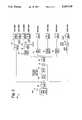
- FIG. 3it shows a diagram of a portion of a reference generator 30 employing the tone generator 10a of FIG. 2 that was built for a particular radio application.
- the present inventionrequires a single reference source to generate eight local oscillator signals needed to tune from 2 MHz to 2 GHz in 200 MHz steps for a tone generator used in a man-portable radio currently under development by the assignee of the present invention. This allows the radio to be implemented in a very small volume (which is a requirement for the man-portable radio), and with much lower power and cost.
- the output of the divider 13ais filtered to preclude all except the fundamental, second, third, and fourth harmonics (f 0 , 2f 0 , 3f 0 , 4f 0 ), and then mixed with reference frequency signal.
- Thisprovides for the generation of signals of 800 MHz, 1400 MHz, 1800 MHz, and 2000 MHz as was described above.
- the 1200 MHz reference frequency signalis also used.
- the 1200 MHz and 1400 MHz signalsare then frequency doubled by frequency doublers 24, 25 (identified as X2 in FIG. 3) to obtain two other signals at 2400 MHz and 2800 MHz.
- the final signalis obtained by mixing the 1200 MHz fundamental frequency signals and the 1400 MHz signal, resulting in an eighth local oscillator tone at 2600 MHz.
- the present inventionis applicable to products requiring a series of tones that are harmonically related.
- the above-cited radio for which this invention was specifically developedis a very wide band communications transceiver.
- the multiple tonesare used to provide coarse frequency tuning (in sub-bands) of a 2 GHz frequency band.
- only one frequency reference sourceis needed to generate the eight frequency tones needed to tune 2000 MHz in 200 MHz sub-bands.
- the present inventionmay be also applied to communications needs of automobiles, such as wide band radio receivers, or other wide band commercial applications.
Landscapes
- Manipulation Of Pulses (AREA)
Abstract
Description
Claims (6)
Priority Applications (1)
| Application Number | Priority Date | Filing Date | Title |
|---|---|---|---|
| US07/911,597US5307029A (en) | 1992-07-10 | 1992-07-10 | Method and apparatus for generating multiple frequency tones using a digital frequency divider |
Applications Claiming Priority (1)
| Application Number | Priority Date | Filing Date | Title |
|---|---|---|---|
| US07/911,597US5307029A (en) | 1992-07-10 | 1992-07-10 | Method and apparatus for generating multiple frequency tones using a digital frequency divider |
Publications (1)
| Publication Number | Publication Date |
|---|---|
| US5307029Atrue US5307029A (en) | 1994-04-26 |
Family
ID=25430533
Family Applications (1)
| Application Number | Title | Priority Date | Filing Date |
|---|---|---|---|
| US07/911,597Expired - LifetimeUS5307029A (en) | 1992-07-10 | 1992-07-10 | Method and apparatus for generating multiple frequency tones using a digital frequency divider |
Country Status (1)
| Country | Link |
|---|---|
| US (1) | US5307029A (en) |
Cited By (18)
| Publication number | Priority date | Publication date | Assignee | Title |
|---|---|---|---|---|
| US5369373A (en)* | 1992-10-16 | 1994-11-29 | Unisys Corporation | Comb data generation |
| US20020154683A1 (en)* | 2001-01-26 | 2002-10-24 | Cook Dean Lawrence | Single oscillator transceiver frequency plan |
| US20030040292A1 (en)* | 2001-01-12 | 2003-02-27 | Peterzell Paul E. | Local oscillator leakage control in direct conversion processes |
| US20040037353A1 (en)* | 2000-08-10 | 2004-02-26 | Markku Henriksson | Testing a transceiver |
| US20040097206A1 (en)* | 2001-05-11 | 2004-05-20 | Christian Grewing | Circuit configuration for the frequency conversion of an oscillator frequency into a carrier frequency |
| US6850121B1 (en)* | 1999-06-24 | 2005-02-01 | Siemens Aktiengesellschaft | TDMA transmit frequency generator suppressing frequency jumps caused by feedback |
| US20050054310A1 (en)* | 2003-09-10 | 2005-03-10 | Sparks Stephen T. | Heterodyne system |
| US20050212604A1 (en)* | 2004-02-10 | 2005-09-29 | Cyr Russell J | Programmable radio transceiver |
| US20060030277A1 (en)* | 2004-02-10 | 2006-02-09 | Cyr Russell J | Programmable radio transceiver |
| US20070139124A1 (en)* | 2005-12-20 | 2007-06-21 | Stadius Kari R | Frequency generator arrangement |
| US20070293163A1 (en)* | 2006-06-15 | 2007-12-20 | John Kilpatrick | Programmable transmitter architecture for non-constant and constant envelope modulation |
| US20080007365A1 (en)* | 2006-06-15 | 2008-01-10 | Jeff Venuti | Continuous gain compensation and fast band selection in a multi-standard, multi-frequency synthesizer |
| US20080100387A1 (en)* | 2006-10-25 | 2008-05-01 | Jinghong Chen | Multiple frequency generator for quadrature amplitude modulated communications |
| RU2336626C2 (en)* | 2001-01-12 | 2008-10-20 | Квэлкомм Инкорпорейтед | Method of heterodyne signal penetration control in direct conversion methods |
| US20100112961A1 (en)* | 2001-01-26 | 2010-05-06 | Dean Lawrence Cook | Single oscillator transceiver |
| US20100117693A1 (en)* | 2008-11-07 | 2010-05-13 | Viasat, Inc. | Dual conversion transmitter with single local oscillator |
| US20130070832A1 (en)* | 2010-10-29 | 2013-03-21 | Maxim Integrated Products, Inc. | Digital frequency divider |
| US20140341214A1 (en)* | 2008-07-16 | 2014-11-20 | Freescale Semiconductor, Inc. | Method and apparatus for detecting one or more predetermined tones transmitted over a communication network |
Citations (2)
| Publication number | Priority date | Publication date | Assignee | Title |
|---|---|---|---|---|
| US3668327A (en)* | 1969-11-20 | 1972-06-06 | Farinon Electric | Carrier supply for multiplex communication system |
| US3777271A (en)* | 1971-10-04 | 1973-12-04 | Cutler Hammer Inc | Generation of microwave frequency combs with narrow line spacing |
- 1992
- 1992-07-10USUS07/911,597patent/US5307029A/ennot_activeExpired - Lifetime
Patent Citations (2)
| Publication number | Priority date | Publication date | Assignee | Title |
|---|---|---|---|---|
| US3668327A (en)* | 1969-11-20 | 1972-06-06 | Farinon Electric | Carrier supply for multiplex communication system |
| US3777271A (en)* | 1971-10-04 | 1973-12-04 | Cutler Hammer Inc | Generation of microwave frequency combs with narrow line spacing |
Cited By (44)
| Publication number | Priority date | Publication date | Assignee | Title |
|---|---|---|---|---|
| US5369373A (en)* | 1992-10-16 | 1994-11-29 | Unisys Corporation | Comb data generation |
| US6850121B1 (en)* | 1999-06-24 | 2005-02-01 | Siemens Aktiengesellschaft | TDMA transmit frequency generator suppressing frequency jumps caused by feedback |
| US6940263B2 (en)* | 2000-08-10 | 2005-09-06 | Nokia Corporation | Testing a transceiver |
| US20040037353A1 (en)* | 2000-08-10 | 2004-02-26 | Markku Henriksson | Testing a transceiver |
| RU2336626C2 (en)* | 2001-01-12 | 2008-10-20 | Квэлкомм Инкорпорейтед | Method of heterodyne signal penetration control in direct conversion methods |
| US20030040292A1 (en)* | 2001-01-12 | 2003-02-27 | Peterzell Paul E. | Local oscillator leakage control in direct conversion processes |
| AU2002245251B2 (en)* | 2001-01-12 | 2007-02-08 | Qualcomm Incorporated | Local oscillator leakage control in direct conversion processes |
| US6960962B2 (en)* | 2001-01-12 | 2005-11-01 | Qualcomm Inc. | Local oscillator leakage control in direct conversion processes |
| US20100112961A1 (en)* | 2001-01-26 | 2010-05-06 | Dean Lawrence Cook | Single oscillator transceiver |
| US20020154683A1 (en)* | 2001-01-26 | 2002-10-24 | Cook Dean Lawrence | Single oscillator transceiver frequency plan |
| US8116358B2 (en) | 2001-01-26 | 2012-02-14 | Viasat, Inc. | Single oscillator transceiver |
| US8116359B2 (en) | 2001-01-26 | 2012-02-14 | Viasat, Inc. | Single oscillator transceiver |
| US20110075714A1 (en)* | 2001-01-26 | 2011-03-31 | Viasat, Inc. | Single oscillator transceiver |
| US6996165B2 (en)* | 2001-01-26 | 2006-02-07 | U.S. Monolithics, L.L.C. | Single oscillator transceiver frequency plan |
| US7848395B2 (en) | 2001-01-26 | 2010-12-07 | Viasat, Inc. | Single oscillator transceiver |
| US20060135082A1 (en)* | 2001-01-26 | 2006-06-22 | U.S. Monolithics, L.L.C. | Single oscillator transceiver frequency plan |
| US7116706B2 (en)* | 2001-01-26 | 2006-10-03 | U.S. Monolithics, L.L.C. | Single oscillator transceiver frequency plan |
| US20070015471A1 (en)* | 2001-01-26 | 2007-01-18 | Cook Dean L | Single oscillator transceiver |
| US20030007550A1 (en)* | 2001-01-26 | 2003-01-09 | Cook Dean Lawrence | Single oscillator transceiver frequency plan |
| US7272170B2 (en) | 2001-01-26 | 2007-09-18 | U.S. Monolithics, L.L.C. | Single oscillator transceiver |
| US20040097206A1 (en)* | 2001-05-11 | 2004-05-20 | Christian Grewing | Circuit configuration for the frequency conversion of an oscillator frequency into a carrier frequency |
| US20050054310A1 (en)* | 2003-09-10 | 2005-03-10 | Sparks Stephen T. | Heterodyne system |
| US20050227627A1 (en)* | 2004-02-10 | 2005-10-13 | Cyr Russell J | Programmable radio transceiver |
| US20050212604A1 (en)* | 2004-02-10 | 2005-09-29 | Cyr Russell J | Programmable radio transceiver |
| US7323945B2 (en)* | 2004-02-10 | 2008-01-29 | Bitwave Semiconductor, Inc. | Programmable radio transceiver |
| US20050261797A1 (en)* | 2004-02-10 | 2005-11-24 | Cyr Russell J | Programmable radio transceiver |
| US20060030277A1 (en)* | 2004-02-10 | 2006-02-09 | Cyr Russell J | Programmable radio transceiver |
| US7482887B2 (en) | 2004-02-10 | 2009-01-27 | Bitwave Semiconductor, Inc. | Multi-band tunable resonant circuit |
| US7508898B2 (en) | 2004-02-10 | 2009-03-24 | Bitwave Semiconductor, Inc. | Programmable radio transceiver |
| US20090079524A1 (en)* | 2004-02-10 | 2009-03-26 | Bitwave Semiconductor, Inc. | Multi-band tunable resonant circuit |
| US7580684B2 (en) | 2004-02-10 | 2009-08-25 | Bitwave Semiconductor, Inc. | Programmable radio transceiver |
| US20070139124A1 (en)* | 2005-12-20 | 2007-06-21 | Stadius Kari R | Frequency generator arrangement |
| US7268640B2 (en)* | 2005-12-20 | 2007-09-11 | Nokia Corporation | Frequency generator arrangement |
| US20080007365A1 (en)* | 2006-06-15 | 2008-01-10 | Jeff Venuti | Continuous gain compensation and fast band selection in a multi-standard, multi-frequency synthesizer |
| US7672645B2 (en) | 2006-06-15 | 2010-03-02 | Bitwave Semiconductor, Inc. | Programmable transmitter architecture for non-constant and constant envelope modulation |
| US20070293163A1 (en)* | 2006-06-15 | 2007-12-20 | John Kilpatrick | Programmable transmitter architecture for non-constant and constant envelope modulation |
| US7598815B2 (en)* | 2006-10-25 | 2009-10-06 | Agere Systems Inc. | Multiple frequency generator for quadrature amplitude modulated communications |
| US20080100387A1 (en)* | 2006-10-25 | 2008-05-01 | Jinghong Chen | Multiple frequency generator for quadrature amplitude modulated communications |
| US20140341214A1 (en)* | 2008-07-16 | 2014-11-20 | Freescale Semiconductor, Inc. | Method and apparatus for detecting one or more predetermined tones transmitted over a communication network |
| US9185471B2 (en)* | 2008-07-16 | 2015-11-10 | Freescale Semiconductor, Inc. | Method and apparatus for detecting one or more predetermined tones transmitted over a communication network |
| US8385855B2 (en) | 2008-11-07 | 2013-02-26 | Viasat, Inc. | Dual conversion transmitter with single local oscillator |
| US20100117693A1 (en)* | 2008-11-07 | 2010-05-13 | Viasat, Inc. | Dual conversion transmitter with single local oscillator |
| US20130070832A1 (en)* | 2010-10-29 | 2013-03-21 | Maxim Integrated Products, Inc. | Digital frequency divider |
| US8432061B2 (en)* | 2010-10-29 | 2013-04-30 | Maxim Integrated Products, Inc. | Digital frequency divider |
Similar Documents
| Publication | Publication Date | Title |
|---|---|---|
| US5307029A (en) | Method and apparatus for generating multiple frequency tones using a digital frequency divider | |
| US5317284A (en) | Wide band, low noise, fine step tuning, phase locked loop frequency synthesizer | |
| US5151661A (en) | Direct digital FM waveform generator for radar systems | |
| GB1458405A (en) | Electronic musical instruments | |
| US5752175A (en) | Frequency synthesizer for V/UHF wideband receiver | |
| US4494073A (en) | Frequency generator using composite digitally controlled oscillators | |
| CA2107632A1 (en) | Local Oscillator and Its Frequency Switching Method | |
| JP2003534700A (en) | Rotation frequency synthesizer | |
| US5442670A (en) | Circuit for dividing clock frequency by N.5 where N is an integer | |
| US4258436A (en) | Multichannel RF signal generator | |
| US4077010A (en) | Digital pulse doubler with 50 percent duty cycle | |
| CN117081588A (en) | Broadband low-phase-noise agile frequency synthesizer and signal synthesis method thereof | |
| US4086545A (en) | Phase locked loop type transmitter receiver | |
| US4878027A (en) | Direct frequency synthesizer using powers of two synthesis techniques | |
| CN212726992U (en) | K wave band frequency sweeping source | |
| US3870970A (en) | Frequency dividing circuit | |
| US2920284A (en) | Signal generator having independent output frequency and phase adjustment means | |
| JP3091423B2 (en) | Accurate digital phase shifter | |
| US3448401A (en) | Digital frequency synthesizer eliminating high speed counters | |
| US3529260A (en) | Oscillator with frequency dividers for providing tunable sinusoidal outputs | |
| US5422594A (en) | Multi-channel carrier wave generator | |
| CN206302402U (en) | A Microwave Analog Signal Generator | |
| US6493410B1 (en) | Wide band high resolution synthesizer | |
| US4381461A (en) | Frequency synthesizer | |
| US5596290A (en) | Direct frequency synthesizer having moderate bandwidth |
Legal Events
| Date | Code | Title | Description |
|---|---|---|---|
| AS | Assignment | Owner name:HUGHES AIRCRAFT COMPANY, A DE CORP., CALIFORNIA Free format text:ASSIGNMENT OF ASSIGNORS INTEREST.;ASSIGNOR:SCHENK, D. STUART;REEL/FRAME:006203/0864 Effective date:19920710 | |
| STCF | Information on status: patent grant | Free format text:PATENTED CASE | |
| FPAY | Fee payment | Year of fee payment:4 | |
| FPAY | Fee payment | Year of fee payment:8 | |
| AS | Assignment | Owner name:HE HOLDINGS, INC., A DELAWARE CORP., CALIFORNIA Free format text:CHANGE OF NAME;ASSIGNOR:HUGHES AIRCRAFT COMPANY, A CORPORATION OF THE STATE OF DELAWARE;REEL/FRAME:016087/0541 Effective date:19971217 Owner name:RAYTHEON COMPANY, MASSACHUSETTS Free format text:MERGER;ASSIGNOR:HE HOLDINGS, INC. DBA HUGHES ELECTRONICS;REEL/FRAME:016116/0506 Effective date:19971217 | |
| FPAY | Fee payment | Year of fee payment:12 | |
| AS | Assignment | Owner name:OL SECURITY LIMITED LIABILITY COMPANY, DELAWARE Free format text:ASSIGNMENT OF ASSIGNORS INTEREST;ASSIGNOR:RAYTHEON COMPANY;REEL/FRAME:029215/0160 Effective date:20120730 |