US5306292A - Heart stimulation apparatus - Google Patents
Heart stimulation apparatusDownload PDFInfo
- Publication number
- US5306292A US5306292AUS08/060,546US6054693AUS5306292AUS 5306292 AUS5306292 AUS 5306292AUS 6054693 AUS6054693 AUS 6054693AUS 5306292 AUS5306292 AUS 5306292A
- Authority
- US
- United States
- Prior art keywords
- electrode
- stimulation
- combination
- threshold
- electrode surfaces
- Prior art date
- Legal status (The legal status is an assumption and is not a legal conclusion. Google has not performed a legal analysis and makes no representation as to the accuracy of the status listed.)
- Expired - Lifetime
Links
- 230000000638stimulationEffects0.000titleclaimsabstractdescription89
- 210000005003heart tissueAnatomy0.000claimsabstractdescription19
- 238000005265energy consumptionMethods0.000claimsabstractdescription7
- 239000004020conductorSubstances0.000claimsdescription28
- 239000012229microporous materialSubstances0.000claimsdescription7
- 238000005342ion exchangeMethods0.000claimsdescription5
- 239000000463materialSubstances0.000claimsdescription5
- 230000000472traumatic effectEffects0.000claimsdescription5
- 239000011248coating agentSubstances0.000claimsdescription4
- 238000000576coating methodMethods0.000claimsdescription4
- 229940079593drugDrugs0.000claimsdescription4
- 239000003814drugSubstances0.000claimsdescription4
- 230000003213activating effectEffects0.000claims4
- 230000003993interactionEffects0.000claims2
- 238000001727in vivoMethods0.000claims1
- 238000012360testing methodMethods0.000abstractdescription26
- 230000006870functionEffects0.000description29
- 238000009413insulationMethods0.000description8
- 230000004936stimulating effectEffects0.000description5
- 239000002245particleSubstances0.000description3
- 230000003110anti-inflammatory effectEffects0.000description2
- 238000010586diagramMethods0.000description2
- 238000012986modificationMethods0.000description2
- 230000004048modificationEffects0.000description2
- NRTOMJZYCJJWKI-UHFFFAOYSA-NTitanium nitrideChemical compound[Ti]#NNRTOMJZYCJJWKI-UHFFFAOYSA-N0.000description1
- 230000008901benefitEffects0.000description1
- 230000015572biosynthetic processEffects0.000description1
- 230000000747cardiac effectEffects0.000description1
- 230000008859changeEffects0.000description1
- 238000011109contaminationMethods0.000description1
- 239000011810insulating materialSubstances0.000description1
- 230000010287polarizationEffects0.000description1
- 210000001519tissueAnatomy0.000description1
Images


Classifications
- A—HUMAN NECESSITIES
- A61—MEDICAL OR VETERINARY SCIENCE; HYGIENE
- A61N—ELECTROTHERAPY; MAGNETOTHERAPY; RADIATION THERAPY; ULTRASOUND THERAPY
- A61N1/00—Electrotherapy; Circuits therefor
- A61N1/02—Details
- A61N1/04—Electrodes
- A61N1/05—Electrodes for implantation or insertion into the body, e.g. heart electrode
- A61N1/056—Transvascular endocardial electrode systems
- A61N1/0565—Electrode heads
Definitions
- the present inventionrelates to a heart stimulation apparatus for intracardial stimulation of heart tissue and/or sensing heart signals of the type having an electrode lead with an electrode head at the distal end thereof, the electrode head having at least first and second conductive surfaces for stimulating heart tissue and/or sensing heart signals respective connected to first and second separate conductors, the conductive surfaces being insulated from each other, and a stimulation pulse generator and/or a heart signal detector and a switch for connecting one conductive surface, or a plurality of the conductive surfaces, to the stimulation pulse generator and/or the detector in any desired manner.
- a heart stimulation apparatusis disclosed in U.S. Pat. No. 4,628,934 in which an electrode lead can be provided with a plurality of independently connectable electrodes.
- the electrodesinclude a plurality of ring electrodes installed relatively far apart, and a conductive electrode tip.
- a switching stageis provided for connecting the electrodes in selected combinations to the pacemaker circuitry in a manner determined by a physician to be best suited for a given pacing function. Each electrode is individually tested to determine its capture threshold.
- Another electrode deviceis known from U.S. Pat. No. 3,911,928 wherein a plurality of relatively small conductive surfaces are arrayed on the head of the electrode device in order to reduce the threshold value and also to reduce thus energy consumption. All the conductive surfaces on the head of this electrode device are connected to the same conductor. This can result in needlessly large energy consumption, since some of the conductive surfaces are not in contact with heart tissue for stimulation.
- U.S. Pat. No. 4,760,852describes a pacemaker electrode with a plurality of relatively large conductive surfaces connected to the same conductor disposed at a distal end of the electrode device.
- a heart stimulation apparatusconstructed in accordance with the principles of the present invention having a switch, controlled by an autocapture function unit such that the respective conductive surfaces at the distal end of the electrode lead are automatically connected in different combinations, via their respective conductors, to the stimulation pulse generator in order to achieve optimal stimulation with minimized energy consumption.
- a combination of stimulation surfaces which provides the lowest stimulation thresholdis automatically selected.
- the term “combination of stimulation surfaces”encompasses a “combination” consisting of only one stimulation surface.
- At least one conductive surfaceserves as the stimulation electrode, and a different conductive surface serves as an indifferent electrode.
- a stimulation pulsemay be delivered unipolarly via one of the surfaces, a combination of two surfaces or three surfaces, or bipolarly between two single surfaces or between a single surface and a double surface.
- the autocapture unittests all possible combinations or a selected number of combinations programmed by a physician.
- the stimulation pulsescould also be displaced in time and exhibit differed amplitudes at the different surfaces. This means that the duration of the pulses could vary, but it also means that a second pulse could arrive before a preceding pulse emitted. In this manner, a pulse can be given the exact morphology desired.
- the sensing of heart signalscan be made from the surfaces providing the lowest sensing threshold.
- the stimulation pulse generator and the heart signal detectorcan be referred to in common as circuits for performing cardiac-assist functions which are adjustable according to an electrical threshold of the cardiac tissue (the threshold possibly being different for the different cardiac assist functions, i.e., a stimulation threshold or a sensing threshold).
- the conductive surface providing the lowest stimulation thresholdis connected to a negative output of the stimulation pulse generator.
- the number and choice of conductive surfaces, connected via the conductor(s) to the detector for sensing,are selected independently of the conductive surface(s) employed for stimulation. This results in a large election of sensing surfaces on the electrode head. All conductive surfaces or the electrode head can be connectable to both the pulse generator and the signal detector, but a surface selected for use as a stimulation surface may then be inhibited, for a short time, from selection for use as a sensing surface. This is an advantage in sensing immediately after a stimulation, since the stimulating surface is then polarized at a relatively large voltage, and any sensing of the much lower level heart signals could be masked by the stimulation surface's polarization voltage.
- the conductive surfacesare uniformly distributed over the electrode head. In this way, one or more electrode surfaces would always be optimally placed against heart tissue.
- the electrode headis hemispherical and the conductive surfaces are arrayed close to one another. In this manner, a relatively large number of conductive surfaces can be disposed on a very small electrode head.
- the shape of the electrode headensures that heart tissue is not damaged.
- the center of the electrode headhas a projecting part with a conductive surface. Since the projecting part is extremely small, this part has at least a chance of retaining contact with heart tissue if the electrode head becomes dislocated.
- the electrode headconsists of at least two conductive bodies which are insulated from one another.
- the electrode headcan have a configuration in which one of the conductive bodies is displaced in relation to the other.
- the free end of the projecting partin addition to the sides of the free end, can be insulated to prevent any conduction between the conductive surfaces of the bodies.
- the conductive surfaces of one body or another, or of both bodiescan be used for simultaneous stimulation of heart tissue and/or sensing of heart signals.
- the electrode headis equipped with a traumatic fixing component on which at least one conductive surface is provided. This achieves both fixing of the electrode head to the heart wall and ensures that at least two conductive surfaces are in contact with heart tissue.
- the fixing componentis helical. In this way, the electrode head can be partially screwed into heart issue.
- At east one of the conductive surfacesis made of a microporous material.
- the stimulation electrode and the indifferent electrodecan be made very mall while the conductive surfaces are relatively large at the same time.
- At least one of the conductive surfacescan also be coated with a layer of ion exchange material.
- the ion exchange materialserves, e.g., as protection against contamination particles.
- the conductive surfacesare highly sensitive to such particles, particularly if the surfaces are made from a microporous material.
- a coating of medicationcan be applied on at least one of the conductive surfaces.
- This coatinghas an anti-inflammatory effect when the electrode head dresses against or is screwed into the heart wall. In this manner, formation of fibrous tissue around the electrode head, which otherwise could occur, is avoided or reduced.
- FIG. 1is a side view of a heart stimulation apparatus having an electrode device according to the invention, shown with an enlarged electrode head, partly in cross-section.
- FIG. 2is a block diagram illustrating the autocapture arrangement in more detail.
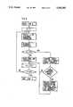
- FIG. 3illustrates in a flow chart for one possible autocapture routine which the heart stimulation apparatus may perform.
- FIG. 4illustrates in a flow chart for another possible autocapture routine which the heart stimulation apparatus may perform.
- FIG. 5is a frontal view of an electrode head according to FIG. 1.
- FIG. 6is a cross-section of the electrode device through the section line III-III in FIG. 1.
- FIG. 7is a side view of another embodiment of a heart stimulation apparatus having an electrode device according to the invention, with an enlarged electrode head shown in a cross section.
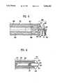
- FIG. 8is a side view of the distal end of the electrode device, shown in cross-section, according to the invention.
- FIG. 9is a side view of another embodiment of the distal end of the electrode device, shown in cross-section, according to the invention.
- FIG. 1depicts a heart stimulation apparatus 14 for intracardial stimulation of the heart tissue of a patient and/or sensing heart signals.
- the apparatus 14includes an electrode device 1 containing an electrode cable 2 equipped with a hemispherical electrode head 3 at its distal end.
- the electrode head 3is fitted with four round, closely spaced conductive surfaces 4, 5, 6 and 7 which are uniformly distributed on the electrode head 3 and which are electrically separated by insulating material 8.
- the conductive surface 7is hidden, but can be seen in FIG. 2.
- Each conductive surface 4, 5, 6 and 7is connected to its own elongate, flexible conductor 9, 10, 11 and 12 extending to the proximal end of the electrode cable.
- the conductors 9, 10, 11 and 12are insulated from one another.
- the electrode cable 2is also provided with an external layer of insulation 13.
- the heart stimulation apparatus 14is connected to the proximal end of the electrode cable 2.
- the heart stimulation apparatus 14further includes a switch unit 15 with four output terminals 16, 17, 18 and 19, respectively connected to conductors 9, 10, 11 and 12 for the conductive surfaces 4, 5, 6 and 7 on the electrode head 3.
- the switch unit 15also has an electronics unit 20 connected to the output terminals 16, 17, 18, 19.
- the heart stimulation apparatus 14additionally contains a stimulation pulse generator 21 and a detector 22 for sensing heart signals, each individually connected to the electronics unit 20, and an autocapture function unit 23 which is connected to the stimulation pulse generator 21, to the detector 22 and to the electronics unit 20.
- FIG. 2shows that the conductive surfaces 4, 5, 6 and 7 are uniformly arrayed on the electrode head 3.
- the conductive surfaces 4, 5, 6 and 7are at the ends of wires consisting of a conductive material whose other ends are connected to one of the conductors 9, 10, 11 and 12, insulated from one another, as shown in cross-section through the electrode device in FIG. 3.
- the stimulation generator 21is switched via the electronics unit 20, e.g., via output terminal 8 and conductor 11, to the conductive surface 6, a voltage for stimulating the heart tissue then being applied to the surface 6.
- the detector 22is then switched in the same way, via the electronics unit 20, via one or more of the output terminals 16, 17, 18 and 19 and via the corresponding conductor 9, 10, 11 and/or 12, to one or more conductive surfaces 4, 5, 6 and/or 7 for sensing heart signals.
- the number and selection of conductive surfaces 4, 5, 6 and 7 connected to the detector 22, via one or more of the conductors 9, 10, 11 and 12,can be selected independently of the conductive surface(s) 4, 5, 6 and 7 employed for sensing. All conductive surfaces 4, 5, 6 and 7 can be switched for connection to the detector 22.
- FIG. 4the circuitry in the heart stimulation apparatus 14 which executes the autocapture function and selection of electrode surface configuration is shown in a block diagram.
- the stimulation pulse generator 21, detector 22 and autocapture function unit 23are, as also shown in FIG. 1, connected to the electronics unit 20.
- a first switch 121is connected between the output terminal 16 and the stimulation pulse generator 21
- a second switch 122is connected between the output terminal 17 and the stimulation pulse generator 21
- a third switch 123is connected between the output terminal 18 and the stimulation pulse generator 21
- a fourth switch 124is connected between the output terminal 19 and the stimulation pulse generator 21
- a fifth switch 125is connected between the output terminal 16 and the detector 22
- a sixth switch 126is connected between the output terminal 17 and the detector 22
- a seventh switch 127is connected between the output terminal 18 and the detector 22
- an eighth switch 128is connected between the output terminal 19 and the detector 22.
- the switches 121-128 anwhen activated by the autocapture function unit 23, selectively connect any output terminal 16, 17, 18 and 19 or a combination of output terminals 16, 17, 18, 19 to the pulse generator 21 and/or detector 22 respectively.
- a ninth switch 129can connect neither, either or both of the stimulation pulse generator 21 and detector 22 to the case of the heart stimulation apparatus 14 for unipolar stimulation and sensing.
- the autocapture function unit 23is programmed to automatically search for the conductive surface combination which results in the lowest stimulation threshold. This means that the autocapture function unit 23 will selectively, through the switches 121 to 129, test a sequence of different stimulation arrangements and select the most efficient one.
- the autocapture function in itselfis known (but not for use in the manner disclosed herein). Basically, it is performed by reducing the stimulation energy until there is no reaction from the heart, i.e., no capture, whereafter the stimulation energy is increased until a capture is detected by the detector 22 and the threshold is determined.
- FIG. 5illustrates one possible flow chart for performing a selection of the ten lowest thresholds of all programmed combinations.
- the number of possible combinationscould be larger than the number of programmed combinations. This because it may, for instance, not be suitable to stimulate bipolarly between two conductive surfaces which are located too closely to each other.
- the determined threshold for the actual combinationwill be compared with the stored thresholds and if any stored threshold is higher than the currently determined threshold (YES in block IS STORED THRESHOLD HIGHER?) the stored combination will be replaced with the present combination and threshold.
- the number of tested combinationsis now incremented and the function proceeds as described above.
- this flow chartonly indicates the rudiments of the autocapture function. If the number of possible combinations is large, it could be inconvenient for a patient if the heart stimulation apparatus were to run through all combinations in an uninterrupted sequence.
- the block DETERMINE THRESHOLDcould therefore include timing functions reducing the number of tests per hour or the like. When no specific combination has been selected automatically the heart will be stimulated using either a combination and stimulation energy selected by a physician or a combination and stimulation energy previously chosen by the autocapture function.
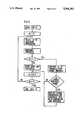
- FIG. 6illustrates a flow chart for a TEST B.
- TEST Bis a continuation of TEST A and in TEST B the stored ten combinations are tested to determine which of the ten has the lowest threshold.
- TEST Bcould be routinely performed by the heart stimulation apparatus 14 to ensure that the combination having the lowest threshold is permanently activated.
- the flow chartbegins with a START TEST B block, which could be initiated automatically at selected time intervals by the autocapture function unit 23.
- the thresholdis determined.
- TEST Bit is only relevant to find the combination having the lowest threshold, and the first threshold will therefore be stored to be compared with other combinations.
- the number for the combinationis incremented and the function controls if all combinations have been checked, in which case TEST B is ended. Otherwise the next combination is selected and its threshold determined.
- the current combination and its thresholdis now compared with the stored combination and threshold and if the stored threshold is higher, the current combination and threshold will replace the previously-stored combination and threshold, and the function proceeds by incrementing the number of combinations.
- the autocapture function unit 23will use the selected combination until a new test may indicate that another combination is preferable, or when a physician by telemetry by means of an external programming unit selects a different combination for stimulation.
- the autocapture function unitmay select a combination of conductive surfaces 4, 5, 6 and/or 7 which provides the best sensing level for the detector 22.
- the autocapture function unit 23may execute all possible unipolar stimulation combinations and permanently select the conductive surface(s) providing the lowest threshold as stimulation electrode in a bipolar combination.
- the conductive surface(s) serving as stimulation electrodeshould in this connection be connected to a negative output of the stimulation pulse generator 21 as this will provide a lower threshold than if the stimulation electrode were to be connected to a positive output.
- the autocapture function unit 23may switch the connection so that the negative conductive surface(s) becomes positive and vice versa.
- the polarity changemay be executed automatically if an increase in the threshold is detected by the autocapture function unit 23, thereby testing which of the two combinations provides the lowest threshold.
- FIG. 7shows a heart stimulation apparatus 224 with a function corresponding to the function shown and described in FIG. 1.
- An electrode device 225whose design only differs from the previously illustrated and described electrode device 1 by having a different configuration for the electrode head, is connected to this heart stimulation apparatus 224.
- the electrode device 225contains a cable 226 at whose distal end an electrode head 227 is provided.
- the electrode head 227consists of two conductive bodies 228 and 229 which are electrically insulated from one another by a layer of insulation 230.
- the center of the body 228is equipped with a through opening in which the body 229 is inserted.
- the bodies 228 and 229are also displaced in relation to one another so the center of the electrode head 27, as seen from the side, has a projecting part formed by the body 229, the side of the partially free end of this body 229 having a conductive surface 231.
- the free surface of the body 228forms a second conductive surface 232. Since the insulation 230 covers the body 229, in addition to the end side, no electrical conduction can occur between the conductive surfaces 231 and 232.
- These conductive surfaces 231 and 232are respectively connected to elongate, flexible, insulated conductors 233 and 234 extending to the proximal end of the electrode cable 226 and being connected to respective output terminals 235 and 236 on a switch 237.
- the switch 237also contains an electronics unit 220 which functions analogously to the previously described electronics unit 20.
- the electronics unit 220is, in turn, connected to a stimulation pulse generator 221, a heart signal detector 222 and a function unit 223 for autocapture.
- the electrode cable 226is also provided with an external layer of insulation 238.
- FIG. 8shows the distal end of a bipolar electrode device for intracardial stimulation of heart tissue in a patient.
- the electrode devicecontains an electrode cable 301 at whose distal end an electrode head 302 with a helical fixing device 303 is installed.
- the electrode head 302is provided with two conductive surfaces 304 and 305, respectively connected to elongate conductors 306 and 307 which run inside the electrode cable 301 and extend to the proximal end of the electrode cable.
- the conductors 306 and 307are insulated from one another by a layer of insulation 308.
- the electrode cable 301is also provided with an external layer of insulation 309. FIG.
- the conductive surfaces 304 and 305are made of a microporous material, such as titanium nitride. To protect these surfaces 304 and 305 from contaminating particles, the surfaces 304 and 305 are coated with a layer of ion exchange material 311 which, in this embodiment, is in turn coated with a layer of medication 312 for providing, e.g., an anti-inflammatory effect when the electrode is implanted.
- the conductors 306 and 307 for the conductive surfaces 304 and 305can be connected optionally to different poles in a pacemaker (not shown) in such a way that conductive surface 304, for example, serves as an indifferent electrode and conductive surface 305 serves as a stimulation electrode.
- conductive surface 304for example, serves as an indifferent electrode and conductive surface 305 serves as a stimulation electrode.
- the conductive surface 305can serve as the indifferent electrode and the conductive surface 304 be used as the stimulation electrode.
- FIG. 9shows a non-traumatic electrode device containing an electrode cable 313 at whose distal end an electrode head 314 is installed.
- the electrode head 314is formed by two conductive bodies 315 and 316 which are electrically insulated from one another by a layer of insulation 317.
- the center of the body 315is provided with a through opening in which the body 316 is installed.
- the bodies 315 and 316are uniformly displaced in relation to one another so the center of the electrode head 314, seen in profile, has a protruding part formed by the body 316, the partially free end side of this body consisting of a conductive surface 318.
- the free surface of the body 315forms a second conductive surface 319.
- the conductive surfaces 318 and 319are respectively connected to an elongate, flexible, individually insulated conductor 320 and 321 which run to the proximal end of the electrode cable 313.
- the electrode cable 313is also provided with an external layer of insulation 322.
- either the conductive surface 318 or the conductive surface 319can be connected to a pacemaker in such a way that either, as described in connection with FIG. 8, can serve as an indifferent electrode or as a stimulation electrode.
- Conductive surfaces 318 and 319which are made of a microporous material, can, like conductive surfaces 304 and 305 in FIG. 8, be coated with an ion exchange material and with a layer of medication, although this is not shown in FIG. 9.
- the electrode head of the electrode device according to the inventionis not limited to the described embodiments. Any configuration can be used wherein the conductive surfaces on the electrode head are electrically insulated from one another, so that one or a desired combination of several conductive surfaces can be used for attaining optimal stimulation with minimal energy consumption.
- the number of conductive surfacesis not limited.
- the size and shape of all or some of the surfacescan vary.
Landscapes
- Health & Medical Sciences (AREA)
- Heart & Thoracic Surgery (AREA)
- Vascular Medicine (AREA)
- Cardiology (AREA)
- Engineering & Computer Science (AREA)
- Biomedical Technology (AREA)
- Nuclear Medicine, Radiotherapy & Molecular Imaging (AREA)
- Radiology & Medical Imaging (AREA)
- Life Sciences & Earth Sciences (AREA)
- Animal Behavior & Ethology (AREA)
- General Health & Medical Sciences (AREA)
- Public Health (AREA)
- Veterinary Medicine (AREA)
- Electrotherapy Devices (AREA)
Abstract
Description
Claims (16)
Applications Claiming Priority (4)
| Application Number | Priority Date | Filing Date | Title |
|---|---|---|---|
| SE9201640ASE9201640D0 (en) | 1992-05-25 | 1992-05-25 | The electrode device |
| SE92016401 | 1992-05-25 | ||
| SE9202479 | 1992-08-28 | ||
| SE9202479ASE9202479D0 (en) | 1992-08-28 | 1992-08-28 | The electrode device |
Publications (1)
| Publication Number | Publication Date |
|---|---|
| US5306292Atrue US5306292A (en) | 1994-04-26 |
Family
ID=26661431
Family Applications (1)
| Application Number | Title | Priority Date | Filing Date |
|---|---|---|---|
| US08/060,546Expired - LifetimeUS5306292A (en) | 1992-05-25 | 1993-05-13 | Heart stimulation apparatus |
Country Status (4)
| Country | Link |
|---|---|
| US (1) | US5306292A (en) |
| EP (1) | EP0571797B2 (en) |
| JP (1) | JPH0670990A (en) |
| DE (1) | DE69321030T3 (en) |
Cited By (42)
| Publication number | Priority date | Publication date | Assignee | Title |
|---|---|---|---|---|
| EP0698400A1 (en) | 1994-08-19 | 1996-02-28 | Pacesetter AB | Electrode device for intracardiac stimulation of heart tissue and/or sensing heart signals in a patient |
| US20020138105A1 (en)* | 2001-03-21 | 2002-09-26 | Kralik Michael R. | Temporary biventricular pacing of heart after heart surgery |
| US6463334B1 (en) | 1998-11-02 | 2002-10-08 | Cardiac Pacemakers, Inc. | Extendable and retractable lead |
| US6501990B1 (en) | 1999-12-23 | 2002-12-31 | Cardiac Pacemakers, Inc. | Extendable and retractable lead having a snap-fit terminal connector |
| US6501994B1 (en)* | 1997-12-24 | 2002-12-31 | Cardiac Pacemakers, Inc. | High impedance electrode tip |
| US6505082B1 (en) | 1998-07-22 | 2003-01-07 | Cardiac Pacemakers, Inc. | Single pass lead system |
| US6526321B1 (en)* | 1998-06-05 | 2003-02-25 | Intermedics, Inc. | Method for making cardiac leads with zone insulated electrodes |
| EP1314450A2 (en) | 2001-11-27 | 2003-05-28 | St. Jude Medical AB | Method and circuit for detecting cardiac rhythm abnormalities by analyzing time differences between unipolar signals from a lead with a multi-electrode tip |
| EP1316329A2 (en) | 2001-11-30 | 2003-06-04 | St. Jude Medical AB | Method and circuit for detecting cardiac rhythm abnormalities using a differential signal from a lead with a multi-electrode tip |
| EP1321168A2 (en) | 2001-12-20 | 2003-06-25 | St. Jude Medical AB | Method and apparatus for detection of premature atrial contraction |
| US6609027B2 (en) | 2001-02-23 | 2003-08-19 | Pacesetter, Inc. | His Bundle sensing device and associated method |
| US6615483B2 (en) | 2000-09-18 | 2003-09-09 | St. Jude Medical Ab | Method for coating a tip region of a multipolar electrode lead |
| US20030213325A1 (en)* | 2002-05-15 | 2003-11-20 | Nguyen Chuong H. | Method for manufacturing a worm shaft for a gearbox and gearbox incorporating same |
| US20030220676A1 (en)* | 2002-05-21 | 2003-11-27 | John R. Helland | Electrode arrangements for body implantable pacing and sensing leads |
| US20040064162A1 (en)* | 2002-09-30 | 2004-04-01 | Manrodt Christopher M. | Method and apparatus for performing stimulation threshold searches |
| US20050070985A1 (en)* | 2003-09-30 | 2005-03-31 | Knapp Christopher P. | Drug-eluting electrode |
| US20060142812A1 (en)* | 2004-12-20 | 2006-06-29 | Action Medical, Inc. | Pacemaker which reestablishes or keeps the physiological electric conduction of the heart and a method of application |
| US7245973B2 (en) | 2003-12-23 | 2007-07-17 | Cardiac Pacemakers, Inc. | His bundle mapping, pacing, and injection lead |
| US7383091B1 (en) | 2003-06-05 | 2008-06-03 | Pacesetter, Inc. | Medical electrical lead providing far-field signal attenuation |
| US20080319499A1 (en)* | 2004-12-20 | 2008-12-25 | Qingsheng Zhu | Devices and Methods for Steering Electrical Stimulation in Cardiac Rhythm Management |
| US20090005846A1 (en)* | 2004-12-20 | 2009-01-01 | Qingsheng Zhu | Methods, Devices and Systems for Cardiac Rhythm Management Using an Electrode Arrangement |
| US20110028966A1 (en)* | 2009-07-29 | 2011-02-03 | Michael Lau | Mono-phasic action potential electrogram recording catheter, and method |
| US8290586B2 (en) | 2004-12-20 | 2012-10-16 | Cardiac Pacemakers, Inc. | Methods, devices and systems for single-chamber pacing using a dual-chamber pacing device |
| US8538521B2 (en) | 2004-12-20 | 2013-09-17 | Cardiac Pacemakers, Inc. | Systems, devices and methods for monitoring efficiency of pacing |
| US8543203B2 (en) | 2004-12-20 | 2013-09-24 | Cardiac Pacemakers, Inc. | Endocardial pacing devices and methods useful for resynchronization and defibrillation |
| US8565880B2 (en) | 2010-04-27 | 2013-10-22 | Cardiac Pacemakers, Inc. | His-bundle capture verification and monitoring |
| US8688234B2 (en) | 2008-12-19 | 2014-04-01 | Cardiac Pacemakers, Inc. | Devices, methods, and systems including cardiac pacing |
| US8880169B2 (en) | 2004-12-20 | 2014-11-04 | Cardiac Pacemakers, Inc. | Endocardial pacing relating to conduction abnormalities |
| US9526637B2 (en) | 2011-09-09 | 2016-12-27 | Enopace Biomedical Ltd. | Wireless endovascular stent-based electrodes |
| US9649487B2 (en) | 2010-08-05 | 2017-05-16 | Enopace Biomedical Ltd. | Enhancing perfusion by contraction |
| US9649494B2 (en) | 2011-04-29 | 2017-05-16 | Medtronic, Inc. | Electrical stimulation therapy based on head position |
| US9789307B2 (en) | 2011-04-29 | 2017-10-17 | Medtronic, Inc. | Dual prophylactic and abortive electrical stimulation |
| EP3431135A1 (en) | 2017-07-18 | 2019-01-23 | Pacesetter, Inc. | System for automated capture threshold testing and associated his bundle pacing |
| US10448889B2 (en) | 2011-04-29 | 2019-10-22 | Medtronic, Inc. | Determining nerve location relative to electrodes |
| WO2020061392A1 (en) | 2018-09-21 | 2020-03-26 | Pacesetter, Inc. | Systems and methods for automated capture threshold testing and associated his bundle pacing |
| WO2020096736A1 (en) | 2018-11-05 | 2020-05-14 | Pacesetter, Inc. | Cardiac stimulation system with automated optimization of his bundle pacing for cardiac resynchronization therapy |
| US10779965B2 (en) | 2013-11-06 | 2020-09-22 | Enopace Biomedical Ltd. | Posts with compliant junctions |
| US11197992B2 (en) | 2005-07-25 | 2021-12-14 | Enopace Biomedical Ltd. | Electrical stimulation of blood vessels |
| US11400299B1 (en) | 2021-09-14 | 2022-08-02 | Rainbow Medical Ltd. | Flexible antenna for stimulator |
| US11452874B2 (en) | 2020-02-03 | 2022-09-27 | Medtronic, Inc. | Shape control for electrical stimulation therapy |
| US20230001215A1 (en)* | 2017-09-15 | 2023-01-05 | Medtronic, Inc. | Electrodes for intra-cardiac pacemaker |
| US11554264B2 (en) | 2020-04-24 | 2023-01-17 | Medtronic, Inc. | Electrode position detection |
Families Citing this family (11)
| Publication number | Priority date | Publication date | Assignee | Title |
|---|---|---|---|---|
| NL9400817A (en)* | 1994-05-18 | 1996-01-02 | Cordis Europ | Catheter with ring electrodes and ablation device comprising these |
| JP3333520B2 (en)* | 1995-10-06 | 2002-10-15 | コーディス ウェブスター,インコーポレイティド | Split tip electrode catheter |
| US5755664A (en)* | 1996-07-11 | 1998-05-26 | Arch Development Corporation | Wavefront direction mapping catheter system |
| US5720775A (en)* | 1996-07-31 | 1998-02-24 | Cordis Corporation | Percutaneous atrial line ablation catheter |
| US6064905A (en)* | 1998-06-18 | 2000-05-16 | Cordis Webster, Inc. | Multi-element tip electrode mapping catheter |
| US6171275B1 (en) | 1998-12-03 | 2001-01-09 | Cordis Webster, Inc. | Irrigated split tip electrode catheter |
| US6210406B1 (en) | 1998-12-03 | 2001-04-03 | Cordis Webster, Inc. | Split tip electrode catheter and signal processing RF ablation system |
| DE19930265A1 (en) | 1999-06-25 | 2000-12-28 | Biotronik Mess & Therapieg | Electrode arrangement |
| DE19930271A1 (en)* | 1999-06-25 | 2000-12-28 | Biotronik Mess & Therapieg | Electrode arrangement |
| US7225035B2 (en) | 2004-06-24 | 2007-05-29 | Medtronic, Inc. | Multipolar medical electrical lead |
| JP5154692B2 (en)* | 2008-04-15 | 2013-02-27 | カーディアック ペースメイカーズ, インコーポレイテッド | His bundle stimulation system |
Citations (13)
| Publication number | Priority date | Publication date | Assignee | Title |
|---|---|---|---|---|
| US3911928A (en)* | 1973-04-14 | 1975-10-14 | Hans Lagergren | Endocardial electrode |
| US4217913A (en)* | 1977-10-10 | 1980-08-19 | Medtronic, Inc. | Body-implantable lead with protected, extendable tissue securing means |
| US4281668A (en)* | 1978-09-28 | 1981-08-04 | Siemens Aktiengesellschaft | Implantable carbon electrode |
| US4611604A (en)* | 1983-01-11 | 1986-09-16 | Siemens Aktiengesellschaft | Bipolar electrode for medical applications |
| US4628943A (en)* | 1985-06-21 | 1986-12-16 | Cordis Corporation | Bipolar screw-in packing lead assembly |
| US4628934A (en)* | 1984-08-07 | 1986-12-16 | Cordis Corporation | Method and means of electrode selection for pacemaker with multielectrode leads |
| US4662382A (en)* | 1985-01-16 | 1987-05-05 | Intermedics, Inc. | Pacemaker lead with enhanced sensitivity |
| US4760852A (en)* | 1985-09-09 | 1988-08-02 | Siemens Aktiengesellschaft | Heart pacemaker electrode having two portions of different conductive properties for stimulating and sensing |
| US4784161A (en)* | 1986-11-24 | 1988-11-15 | Telectronics, N.V. | Porous pacemaker electrode tip using a porous substrate |
| US4848352A (en)* | 1987-02-13 | 1989-07-18 | Telectronics, N.V. | Method for cardiac pacing and sensing using combination of electrodes |
| US4955382A (en)* | 1984-03-06 | 1990-09-11 | Ep Technologies | Apparatus and method for recording monophasic action potentials from an in vivo heart |
| US4964407A (en)* | 1988-08-29 | 1990-10-23 | Intermedics, Inc. | Method and apparatus for assuring pacer programming is compatible with the lead |
| US5018523A (en)* | 1990-04-23 | 1991-05-28 | Cardiac Pacemakers, Inc. | Apparatus for common mode stimulation with bipolar sensing |
- 1993
- 1993-05-07EPEP93107473Apatent/EP0571797B2/ennot_activeExpired - Lifetime
- 1993-05-07DEDE69321030Tpatent/DE69321030T3/ennot_activeExpired - Fee Related
- 1993-05-13USUS08/060,546patent/US5306292A/ennot_activeExpired - Lifetime
- 1993-05-25JPJP5122299Apatent/JPH0670990A/enactivePending
Patent Citations (14)
| Publication number | Priority date | Publication date | Assignee | Title |
|---|---|---|---|---|
| US3911928B1 (en)* | 1973-04-14 | 1988-11-08 | ||
| US3911928A (en)* | 1973-04-14 | 1975-10-14 | Hans Lagergren | Endocardial electrode |
| US4217913A (en)* | 1977-10-10 | 1980-08-19 | Medtronic, Inc. | Body-implantable lead with protected, extendable tissue securing means |
| US4281668A (en)* | 1978-09-28 | 1981-08-04 | Siemens Aktiengesellschaft | Implantable carbon electrode |
| US4611604A (en)* | 1983-01-11 | 1986-09-16 | Siemens Aktiengesellschaft | Bipolar electrode for medical applications |
| US4955382A (en)* | 1984-03-06 | 1990-09-11 | Ep Technologies | Apparatus and method for recording monophasic action potentials from an in vivo heart |
| US4628934A (en)* | 1984-08-07 | 1986-12-16 | Cordis Corporation | Method and means of electrode selection for pacemaker with multielectrode leads |
| US4662382A (en)* | 1985-01-16 | 1987-05-05 | Intermedics, Inc. | Pacemaker lead with enhanced sensitivity |
| US4628943A (en)* | 1985-06-21 | 1986-12-16 | Cordis Corporation | Bipolar screw-in packing lead assembly |
| US4760852A (en)* | 1985-09-09 | 1988-08-02 | Siemens Aktiengesellschaft | Heart pacemaker electrode having two portions of different conductive properties for stimulating and sensing |
| US4784161A (en)* | 1986-11-24 | 1988-11-15 | Telectronics, N.V. | Porous pacemaker electrode tip using a porous substrate |
| US4848352A (en)* | 1987-02-13 | 1989-07-18 | Telectronics, N.V. | Method for cardiac pacing and sensing using combination of electrodes |
| US4964407A (en)* | 1988-08-29 | 1990-10-23 | Intermedics, Inc. | Method and apparatus for assuring pacer programming is compatible with the lead |
| US5018523A (en)* | 1990-04-23 | 1991-05-28 | Cardiac Pacemakers, Inc. | Apparatus for common mode stimulation with bipolar sensing |
Cited By (86)
| Publication number | Priority date | Publication date | Assignee | Title |
|---|---|---|---|---|
| US5609623A (en)* | 1994-08-19 | 1997-03-11 | Pacesetter Ab | Electrode device for intracardiac stimulation of heart tissue and/or sensing heart signals having conductive surfaces relatively positionable with respect to each other by a control element |
| EP0698400A1 (en) | 1994-08-19 | 1996-02-28 | Pacesetter AB | Electrode device for intracardiac stimulation of heart tissue and/or sensing heart signals in a patient |
| US6501994B1 (en)* | 1997-12-24 | 2002-12-31 | Cardiac Pacemakers, Inc. | High impedance electrode tip |
| US20040133259A1 (en)* | 1997-12-24 | 2004-07-08 | Cardiac Pacemakers, Inc. | High impedance electrode tip |
| US6526321B1 (en)* | 1998-06-05 | 2003-02-25 | Intermedics, Inc. | Method for making cardiac leads with zone insulated electrodes |
| US6505082B1 (en) | 1998-07-22 | 2003-01-07 | Cardiac Pacemakers, Inc. | Single pass lead system |
| US8209035B2 (en) | 1998-07-22 | 2012-06-26 | Cardiac Pacemakers, Inc. | Extendable and retractable lead having a snap-fit terminal connector |
| US7774934B2 (en) | 1998-07-22 | 2010-08-17 | Cardiac Pacemakers, Inc. | Method for making a terminal connector |
| US6915169B2 (en) | 1998-07-22 | 2005-07-05 | Cardiac Pacemakers, Inc. | Extendable and retractable lead having a snap-fit terminal connector |
| US7392095B2 (en) | 1998-07-22 | 2008-06-24 | Cardiac Pacemakers, Inc. | Extendable and retractable lead having a snap-fit terminal connector |
| US6983185B2 (en) | 1998-07-22 | 2006-01-03 | Cardiac Pacemakers, Inc. | Lead with terminal connector assembly |
| US8285398B2 (en) | 1998-07-22 | 2012-10-09 | Cardiac Pacemakers, Inc. | Lead with terminal connector assembly |
| US6463334B1 (en) | 1998-11-02 | 2002-10-08 | Cardiac Pacemakers, Inc. | Extendable and retractable lead |
| US6501990B1 (en) | 1999-12-23 | 2002-12-31 | Cardiac Pacemakers, Inc. | Extendable and retractable lead having a snap-fit terminal connector |
| US6615483B2 (en) | 2000-09-18 | 2003-09-09 | St. Jude Medical Ab | Method for coating a tip region of a multipolar electrode lead |
| US6609027B2 (en) | 2001-02-23 | 2003-08-19 | Pacesetter, Inc. | His Bundle sensing device and associated method |
| US7010350B2 (en)* | 2001-03-21 | 2006-03-07 | Kralik Michael R | Temporary biventricular pacing of heart after heart surgery |
| US20020138105A1 (en)* | 2001-03-21 | 2002-09-26 | Kralik Michael R. | Temporary biventricular pacing of heart after heart surgery |
| EP1314450A2 (en) | 2001-11-27 | 2003-05-28 | St. Jude Medical AB | Method and circuit for detecting cardiac rhythm abnormalities by analyzing time differences between unipolar signals from a lead with a multi-electrode tip |
| US6950696B2 (en) | 2001-11-27 | 2005-09-27 | St. Jude Medical Ab | Method and circuit for detecting cardiac rhythm abnormalities by analyzing time differences between unipolar signals from a lead with a multi-electrode tip |
| EP1316329A2 (en) | 2001-11-30 | 2003-06-04 | St. Jude Medical AB | Method and circuit for detecting cardiac rhythm abnormalities using a differential signal from a lead with a multi-electrode tip |
| US6728575B2 (en) | 2001-11-30 | 2004-04-27 | St. Jude Medical Ab | Method and circuit for detecting cardiac rhythm abnormalities using a differential signal from a lead with a multi-electrode tip |
| US6745075B2 (en) | 2001-12-20 | 2004-06-01 | St. Jude Medical Ab | Method and apparatus for detection of premature atrial contraction |
| EP1321168A2 (en) | 2001-12-20 | 2003-06-25 | St. Jude Medical AB | Method and apparatus for detection of premature atrial contraction |
| US20030213325A1 (en)* | 2002-05-15 | 2003-11-20 | Nguyen Chuong H. | Method for manufacturing a worm shaft for a gearbox and gearbox incorporating same |
| US7027852B2 (en) | 2002-05-21 | 2006-04-11 | Pacesetter, Inc. | Lead with distal tip surface electrodes connected in parallel |
| US20030220676A1 (en)* | 2002-05-21 | 2003-11-27 | John R. Helland | Electrode arrangements for body implantable pacing and sensing leads |
| US20040064162A1 (en)* | 2002-09-30 | 2004-04-01 | Manrodt Christopher M. | Method and apparatus for performing stimulation threshold searches |
| WO2004028630A1 (en) | 2002-09-30 | 2004-04-08 | Medtronic, Inc. | Method and apparatus for performing stimulation threshold searches |
| US7738959B2 (en) | 2002-09-30 | 2010-06-15 | Medtronic, Inc. | Method and apparatus for performing stimulation threshold searches |
| US7383091B1 (en) | 2003-06-05 | 2008-06-03 | Pacesetter, Inc. | Medical electrical lead providing far-field signal attenuation |
| US20080215127A1 (en)* | 2003-06-05 | 2008-09-04 | Pacesetter, Inc. | Medical Electrical Lead Providing Far-Field Signal Attenuation |
| US20050070985A1 (en)* | 2003-09-30 | 2005-03-31 | Knapp Christopher P. | Drug-eluting electrode |
| US7953499B2 (en)* | 2003-09-30 | 2011-05-31 | Cardiac Pacemakers, Inc. | Drug-eluting electrode |
| US8078287B2 (en) | 2003-12-23 | 2011-12-13 | Cardiac Pacemakers, Inc. | His bundle mapping, pacing, and injection lead |
| US7245973B2 (en) | 2003-12-23 | 2007-07-17 | Cardiac Pacemakers, Inc. | His bundle mapping, pacing, and injection lead |
| US8838238B2 (en) | 2004-12-20 | 2014-09-16 | Cardiac Pacemakers, Inc. | Ventricular pacing |
| US8437848B2 (en) | 2004-12-20 | 2013-05-07 | Cardiac Pacemakers, Inc. | Apparatus for treating the physiological electric conduction of the heart |
| US8903489B2 (en) | 2004-12-20 | 2014-12-02 | Cardiac Pacemakers, Inc. | Methods, devices and systems for single-chamber pacing using a dual-chamber pacing device |
| US8880169B2 (en) | 2004-12-20 | 2014-11-04 | Cardiac Pacemakers, Inc. | Endocardial pacing relating to conduction abnormalities |
| US20090005846A1 (en)* | 2004-12-20 | 2009-01-01 | Qingsheng Zhu | Methods, Devices and Systems for Cardiac Rhythm Management Using an Electrode Arrangement |
| US20080319499A1 (en)* | 2004-12-20 | 2008-12-25 | Qingsheng Zhu | Devices and Methods for Steering Electrical Stimulation in Cardiac Rhythm Management |
| US20090093859A1 (en)* | 2004-12-20 | 2009-04-09 | Action Medical, Inc. | Apparatus for treating the physiological electric conduction of the heart |
| US9031648B2 (en) | 2004-12-20 | 2015-05-12 | Cardiac Pacemakers, Inc. | Endocardial pacing devices and methods useful for resynchronization and defibrillation |
| US8285376B2 (en) | 2004-12-20 | 2012-10-09 | Cardiac Pacemakers, Inc. | Ventricular pacing |
| US20060142812A1 (en)* | 2004-12-20 | 2006-06-29 | Action Medical, Inc. | Pacemaker which reestablishes or keeps the physiological electric conduction of the heart and a method of application |
| US8290586B2 (en) | 2004-12-20 | 2012-10-16 | Cardiac Pacemakers, Inc. | Methods, devices and systems for single-chamber pacing using a dual-chamber pacing device |
| US8326423B2 (en) | 2004-12-20 | 2012-12-04 | Cardiac Pacemakers, Inc. | Devices and methods for steering electrical stimulation in cardiac rhythm management |
| US8346358B2 (en) | 2004-12-20 | 2013-01-01 | Cardiac Pacemakers, Inc. | Pacemaker which reestablishes or keeps the physiological electric conduction of the heart and a method of application |
| US20090093861A1 (en)* | 2004-12-20 | 2009-04-09 | Action Medical, Inc. | Methods for treating the physiological electric conduction of the heart |
| US8428715B2 (en) | 2004-12-20 | 2013-04-23 | Cardiac Pacemakers, Inc. | Methods for treating the physiological electric conduction of the heart |
| US20090187226A1 (en)* | 2004-12-20 | 2009-07-23 | Action Medical, Inc. | Ventricular pacing |
| US8538521B2 (en) | 2004-12-20 | 2013-09-17 | Cardiac Pacemakers, Inc. | Systems, devices and methods for monitoring efficiency of pacing |
| US8543203B2 (en) | 2004-12-20 | 2013-09-24 | Cardiac Pacemakers, Inc. | Endocardial pacing devices and methods useful for resynchronization and defibrillation |
| US9008768B2 (en) | 2004-12-20 | 2015-04-14 | Cardiac Pacemakers, Inc. | Methods, devices and systems for cardiac rhythm management using an electrode arrangement |
| US8934969B2 (en) | 2004-12-20 | 2015-01-13 | Cardiac Pacemakers, Inc. | Systems, devices and methods for monitoring efficiency of pacing |
| US8423139B2 (en) | 2004-12-20 | 2013-04-16 | Cardiac Pacemakers, Inc. | Methods, devices and systems for cardiac rhythm management using an electrode arrangement |
| US8812106B2 (en) | 2004-12-20 | 2014-08-19 | Cardiac Pacemakers, Inc. | Apparatus for treating the physiological electric conduction of the heart |
| US8825159B2 (en) | 2004-12-20 | 2014-09-02 | Cardiac Pacemakers, Inc. | Devices and methods for steering electrical stimulation in cardiac rhythm management |
| US11197992B2 (en) | 2005-07-25 | 2021-12-14 | Enopace Biomedical Ltd. | Electrical stimulation of blood vessels |
| US8688234B2 (en) | 2008-12-19 | 2014-04-01 | Cardiac Pacemakers, Inc. | Devices, methods, and systems including cardiac pacing |
| US20110028820A1 (en)* | 2009-07-29 | 2011-02-03 | Michael Lau | Mono-phasic action potential electrogram recording catheter, and method |
| US20110028966A1 (en)* | 2009-07-29 | 2011-02-03 | Michael Lau | Mono-phasic action potential electrogram recording catheter, and method |
| US8565851B2 (en) | 2009-07-29 | 2013-10-22 | Medtronic Ablation Frontiers Llc | Mono-phasic action potential electrogram recording catheter, and method |
| US8280477B2 (en)* | 2009-07-29 | 2012-10-02 | Medtronic Cryocath Lp | Mono-phasic action potential electrogram recording catheter, and method |
| US8565880B2 (en) | 2010-04-27 | 2013-10-22 | Cardiac Pacemakers, Inc. | His-bundle capture verification and monitoring |
| US9649487B2 (en) | 2010-08-05 | 2017-05-16 | Enopace Biomedical Ltd. | Enhancing perfusion by contraction |
| US11071861B2 (en) | 2011-04-29 | 2021-07-27 | Medtronic, Inc. | Dual prophylactic and abortive electrical stimulation |
| US11589810B2 (en) | 2011-04-29 | 2023-02-28 | Medtronic, Inc. | Determining nerve location relative to electrodes |
| US9789307B2 (en) | 2011-04-29 | 2017-10-17 | Medtronic, Inc. | Dual prophylactic and abortive electrical stimulation |
| US9649494B2 (en) | 2011-04-29 | 2017-05-16 | Medtronic, Inc. | Electrical stimulation therapy based on head position |
| US10485970B2 (en) | 2011-04-29 | 2019-11-26 | Medtronic, Inc. | Dual prophylactic and abortive electrical stimulation |
| US10448889B2 (en) | 2011-04-29 | 2019-10-22 | Medtronic, Inc. | Determining nerve location relative to electrodes |
| US9526637B2 (en) | 2011-09-09 | 2016-12-27 | Enopace Biomedical Ltd. | Wireless endovascular stent-based electrodes |
| US10828181B2 (en) | 2011-09-09 | 2020-11-10 | Enopace Biomedical Ltd. | Annular antenna |
| US10779965B2 (en) | 2013-11-06 | 2020-09-22 | Enopace Biomedical Ltd. | Posts with compliant junctions |
| US11432949B2 (en) | 2013-11-06 | 2022-09-06 | Enopace Biomedical Ltd. | Antenna posts |
| EP3431135A1 (en) | 2017-07-18 | 2019-01-23 | Pacesetter, Inc. | System for automated capture threshold testing and associated his bundle pacing |
| US12350502B2 (en) | 2017-09-15 | 2025-07-08 | Medtronic, Inc. | Electrodes for intra-cardiac pacemaker |
| US20230001215A1 (en)* | 2017-09-15 | 2023-01-05 | Medtronic, Inc. | Electrodes for intra-cardiac pacemaker |
| WO2020061392A1 (en) | 2018-09-21 | 2020-03-26 | Pacesetter, Inc. | Systems and methods for automated capture threshold testing and associated his bundle pacing |
| WO2020096736A1 (en) | 2018-11-05 | 2020-05-14 | Pacesetter, Inc. | Cardiac stimulation system with automated optimization of his bundle pacing for cardiac resynchronization therapy |
| US11452874B2 (en) | 2020-02-03 | 2022-09-27 | Medtronic, Inc. | Shape control for electrical stimulation therapy |
| US11554264B2 (en) | 2020-04-24 | 2023-01-17 | Medtronic, Inc. | Electrode position detection |
| US12138459B2 (en) | 2020-04-24 | 2024-11-12 | Medtronic, Inc. | Electrode position detection |
| US11400299B1 (en) | 2021-09-14 | 2022-08-02 | Rainbow Medical Ltd. | Flexible antenna for stimulator |
Also Published As
| Publication number | Publication date |
|---|---|
| EP0571797A1 (en) | 1993-12-01 |
| EP0571797B2 (en) | 2005-10-26 |
| JPH0670990A (en) | 1994-03-15 |
| DE69321030D1 (en) | 1998-10-22 |
| EP0571797B1 (en) | 1998-09-16 |
| DE69321030T2 (en) | 1999-05-06 |
| DE69321030T3 (en) | 2006-07-13 |
Similar Documents
| Publication | Publication Date | Title |
|---|---|---|
| US5306292A (en) | Heart stimulation apparatus | |
| US5545183A (en) | Method and apparatus for delivering defibrillation therapy through a sensing electrode | |
| US4030508A (en) | Low output electrode for cardiac pacing | |
| US4532931A (en) | Pacemaker with adaptive sensing means for use with unipolar or bipolar leads | |
| US5085218A (en) | Bipolar myocardial positive fixation lead with improved sensing capability | |
| US6999814B2 (en) | Implantable intravenous cardiac stimulation system with pulse generator housing serving as optional additional electrode | |
| US5935158A (en) | Electrode lead and device for tissue stimulation and/or detection of tissue response | |
| US5018523A (en) | Apparatus for common mode stimulation with bipolar sensing | |
| EP0757578B1 (en) | Apparatus for applying charge-balanced antiarrhythmia shocks | |
| US5385574A (en) | Implantable intravenous cardiac stimulation system with pulse generator housing serving as optional additional electrode | |
| US6418348B1 (en) | Implantable lead with selectively operable electrodes | |
| US5662697A (en) | Transvenous internal cardiac defibrillation apparatus having lead and electrode providing even distribution of electrical charge | |
| US4373531A (en) | Apparatus for physiological stimulation and detection of evoked response | |
| US6516231B1 (en) | Endocardial electrode lead with multiple branches | |
| US6529777B1 (en) | Electrode for tissue stimulation | |
| US5609615A (en) | Implantable cardiac stimulation device with warning system and conductive suture point | |
| US6327498B1 (en) | Implantable stimulation lead for use with an ICD device having automatic capture pacing features | |
| US5235978A (en) | Implantable arrangement for the defibrillation or cardioversion of a heart | |
| US5968086A (en) | Pacing and cardioversion lead systems with shared lead conductors | |
| JPH06190066A (en) | Heart stimulation device | |
| WO2000048665A1 (en) | Endocardial lead with axially mounted electrode | |
| EP0944412A1 (en) | Implantable cardiac stimulation device with warning system | |
| JPH11262536A (en) | Configurable multisite active implantable medical device | |
| HUP0004856A2 (en) | Device for augmentation of electrical conduction and contractility by biphasic cardiac pacing | |
| US6405084B2 (en) | Implantable atrial defibrillator apparatus |
Legal Events
| Date | Code | Title | Description |
|---|---|---|---|
| STPP | Information on status: patent application and granting procedure in general | Free format text:APPLICATION UNDERGOING PREEXAM PROCESSING | |
| AS | Assignment | Owner name:SIEMENS-ELEMA AB, SWEDEN Free format text:ASSIGNMENT OF ASSIGNORS INTEREST;ASSIGNOR:LINDEGREN, ULF;REEL/FRAME:006608/0128 Effective date:19930621 | |
| AS | Assignment | Owner name:PACESETTER AB, SWEDEN Free format text:ASSIGNMENT OF ASSIGNORS INTEREST;ASSIGNOR:AB, SIEMENS-ELEMA;REEL/FRAME:007297/0115 Effective date:19940924 | |
| FEPP | Fee payment procedure | Free format text:PAYOR NUMBER ASSIGNED (ORIGINAL EVENT CODE: ASPN); ENTITY STATUS OF PATENT OWNER: LARGE ENTITY | |
| FPAY | Fee payment | Year of fee payment:4 | |
| FPAY | Fee payment | Year of fee payment:8 | |
| FEPP | Fee payment procedure | Free format text:PAYOR NUMBER ASSIGNED (ORIGINAL EVENT CODE: ASPN); ENTITY STATUS OF PATENT OWNER: LARGE ENTITY Free format text:PAYER NUMBER DE-ASSIGNED (ORIGINAL EVENT CODE: RMPN); ENTITY STATUS OF PATENT OWNER: LARGE ENTITY | |
| FPAY | Fee payment | Year of fee payment:12 |