US5306272A - Advancer for surgical instrument - Google Patents
Advancer for surgical instrumentDownload PDFInfo
- Publication number
- US5306272A US5306272AUS07/970,705US97070592AUS5306272AUS 5306272 AUS5306272 AUS 5306272AUS 97070592 AUS97070592 AUS 97070592AUS 5306272 AUS5306272 AUS 5306272A
- Authority
- US
- United States
- Prior art keywords
- holder
- advancer
- adaptor
- gripping element
- gripping
- Prior art date
- Legal status (The legal status is an assumption and is not a legal conclusion. Google has not performed a legal analysis and makes no representation as to the accuracy of the status listed.)
- Expired - Fee Related
Links
- 210000004556brainAnatomy0.000claimsabstractdescription27
- 238000000034methodMethods0.000claimsdescription7
- 230000006835compressionEffects0.000claimsdescription3
- 238000007906compressionMethods0.000claimsdescription3
- 239000012858resilient materialSubstances0.000claims1
- 244000261422Lysimachia clethroidesSpecies0.000abstractdescription8
- 239000000523sampleSubstances0.000description10
- 210000003625skullAnatomy0.000description4
- 208000014674injuryDiseases0.000description2
- 239000000463materialSubstances0.000description2
- 238000001356surgical procedureMethods0.000description2
- 229910000831SteelInorganic materials0.000description1
- 208000027418Wounds and injuryDiseases0.000description1
- 229910052782aluminiumInorganic materials0.000description1
- XAGFODPZIPBFFR-UHFFFAOYSA-NaluminiumChemical compound[Al]XAGFODPZIPBFFR-UHFFFAOYSA-N0.000description1
- 238000010276constructionMethods0.000description1
- 230000006378damageEffects0.000description1
- 238000005553drillingMethods0.000description1
- 210000004907glandAnatomy0.000description1
- 238000003754machiningMethods0.000description1
- 238000004519manufacturing processMethods0.000description1
- 239000007769metal materialSubstances0.000description1
- 238000000465mouldingMethods0.000description1
- 239000004033plasticSubstances0.000description1
- 239000004417polycarbonateSubstances0.000description1
- 229920000515polycarbonatePolymers0.000description1
- 238000011084recoveryMethods0.000description1
- 229910052710siliconInorganic materials0.000description1
- 239000010703siliconSubstances0.000description1
- 239000010959steelSubstances0.000description1
- 230000008733traumaEffects0.000description1
- 230000000472traumatic effectEffects0.000description1
Images

Classifications
- A—HUMAN NECESSITIES
- A61—MEDICAL OR VETERINARY SCIENCE; HYGIENE
- A61B—DIAGNOSIS; SURGERY; IDENTIFICATION
- A61B90/00—Instruments, implements or accessories specially adapted for surgery or diagnosis and not covered by any of the groups A61B1/00 - A61B50/00, e.g. for luxation treatment or for protecting wound edges
- A61B90/10—Instruments, implements or accessories specially adapted for surgery or diagnosis and not covered by any of the groups A61B1/00 - A61B50/00, e.g. for luxation treatment or for protecting wound edges for stereotaxic surgery, e.g. frame-based stereotaxis
- A61B90/11—Instruments, implements or accessories specially adapted for surgery or diagnosis and not covered by any of the groups A61B1/00 - A61B50/00, e.g. for luxation treatment or for protecting wound edges for stereotaxic surgery, e.g. frame-based stereotaxis with guides for needles or instruments, e.g. arcuate slides or ball joints
- A—HUMAN NECESSITIES
- A61—MEDICAL OR VETERINARY SCIENCE; HYGIENE
- A61B—DIAGNOSIS; SURGERY; IDENTIFICATION
- A61B17/00—Surgical instruments, devices or methods
- A61B2017/0046—Surgical instruments, devices or methods with a releasable handle; with handle and operating part separable
- A61B2017/00469—Surgical instruments, devices or methods with a releasable handle; with handle and operating part separable for insertion of instruments, e.g. guide wire, optical fibre
- Y—GENERAL TAGGING OF NEW TECHNOLOGICAL DEVELOPMENTS; GENERAL TAGGING OF CROSS-SECTIONAL TECHNOLOGIES SPANNING OVER SEVERAL SECTIONS OF THE IPC; TECHNICAL SUBJECTS COVERED BY FORMER USPC CROSS-REFERENCE ART COLLECTIONS [XRACs] AND DIGESTS
- Y10—TECHNICAL SUBJECTS COVERED BY FORMER USPC
- Y10T—TECHNICAL SUBJECTS COVERED BY FORMER US CLASSIFICATION
- Y10T403/00—Joints and connections
- Y10T403/70—Interfitted members
- Y10T403/7047—Radially interposed shim or bushing
- Y10T403/7051—Wedging or camming
- Y10T403/7052—Engaged by axial movement
- Y10T403/7056—Threaded actuator
Definitions
- a neurosurgical instrumente.g., an endoscope, scalpel, etc.
- the instrumentis advanced into the brain until the operable portion of the instrument is positioned adjacent the site of interest, i.e., the site of the brain to be operated on. Then, the instrument is manipulated as appropriate for performing the particular procedure.
- neuroendoscopyThe second type of neurosurgery, referred to herein as neuroendoscopy because it often permits advancing an endoscope into the brain to provide the surgeon with a view of the brain, is much less traumatic to the patient than the first.
- Neuroendoscopyrequires drilling a small hole in the skull, and then advancing one or more surgical instruments and/or endoscopes through the hole into the brain to perform the operation. Neuroendoscopy is preferred when use of it is practicable, for the reason that it causes relatively little trauma to the patient and allows for relatively rapid patient recovery.
- the surgical instrument or instrumentsmust be advanced along a precisely determined path into the brain, to avoid unintentionally damaging the brain. Also, once precisely positioned in the brain, the instruments must be securely held in position, again to avoid unintentional injury to the brain.
- stereotactic framesTo aid the surgeon in advancing an instrument or probe along a precisely predetermined path, devices referred to as stereotactic frames have been introduced.
- a stereotactic framecan be positioned near the patient's skull prior to surgery, and the frame has one or more surgical instrument holders, each of which can securely grip a surgical instrument or probe and hold the probe in a predetermined orientation relative to the brain.
- the Bookler Scope Holderhas a flexible arm that has a fixed end which is mounted on a frame.
- the flexible armsometimes referred to as a gooseneck, has a free end, and the free end can be moved in any direction in three dimensional space relative to the frame, and can be locked relative to the frame once the free end has been placed in the desired position and orientation relative to the frame.
- a neurosurgery instrument holderis connected to the free end of the gooseneck, such that a neurosurgery instrument can be engaged with the holder of the gooseneck.
- the instrumentcan thus be oriented relative to the frame as desired.
- the free endis unlocked, the instrument moved as desired, and the free end locked again in position.
- a devicewhich is engageable with a surgical apparatus for axially advancing a surgical instrument into a patient.
- the device of the present inventionincludes a telescoping advancer which is engageable with the surgical apparatus.
- the advanceris movable from a shortened configuration, wherein the advancer has a first length, to an extended configuration, wherein the advancer has a second length longer than the first.
- the advancerincludes a gripping element for gripping the surgical instrument, such that the surgical instrument is advanced axially into the patient when the advancer is moved toward the extended configuration.
- an axial advancer for advancing a neurosurgery instrument into the brain of a patientincludes an annular adaptor for engaging a surgical apparatus.
- the adaptordefines an axis, and a hollow holder is slidably disposed in the adaptor coaxially with the adaptor.
- an annular resilient gripping elementis disposed in the holder coaxially with the holder.
- the gripping elementis biased to a normal configuration, wherein the gripping element has a first inside diameter that is sufficiently large to permit the surgical instrument to be positioned within the gripping element.
- the gripping elementhas a gripping configuration, wherein the gripping element has a second inside diameter smaller than the first, for gripping the surgical instrument.
- a capis threadably engaged with the holder for selectively moving the gripping element to the gripping configuration to grip a surgical instrument.
- a handleis threadably engaged with the holder and is rotatably engaged with the adaptor for selectively moving the holder axially relative to the adaptor.
- the holderis formed with a seat, and the cap can be rotated to urge the gripping element against the seat and thereby move the gripping element to the gripping configuration.
- the holderhas a longitudinal slot formed in it, and the advancer includes a retaining pin which is attached to the adaptor and which protrudes through the slot to retain the holder within the adaptor.
- the adaptoris configured for engaging an instrument holder on a flexible arm of a surgical apparatus.
- a device for moving a surgical instrument axially relative to a surgical apparatushas an adaptor for engaging the surgical apparatus and a holder slidably disposed in the adaptor. Also, the device has a gripping element that is disposed in the holder and is selectively movable between a normal configuration, wherein the gripping element does not grip the surgical instrument, and a gripping configuration, wherein the gripping element can hold the surgical instrument stationary relative to the holder.
- a methodfor axially advancing a neurosurgery instrument into the brain of a patient along a predetermined path.
- the method of the present inventionincludes the steps of providing a surgical apparatus which is positionable in a predetermined orientation relative to the brain. Also, an advancer is provided which has an extended configuration and a shortened configuration, and the advancer holds the instrument.
- the advanceris engaged with the surgical apparatus, and the surgical instrument is engaged with the advancer such that the surgical instrument is oriented along the predetermined path of advancement into the brain.
- the advancercan then be moved toward the extended configuration to advance the instrument into the brain along the predetermined path.
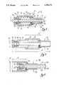
- FIG. 1is a perspective view of the advancer for neurosurgery probe of the present invention, shown in operable engagement with a surgical apparatus and a surgical instrument, with the advancer in the shortened configuration and with portions of the surgical instrument and surgical apparatus broken away;
- FIG. 3is a cross-sectional view of the advancer for neurosurgery probe of the present invention, as seen along the line 3--3 in FIG. 1;
- FIG. 4is a cross-sectional view of the advancer for neurosurgery probe of the present invention, with the advancer in the extended configuration and the gripping element in the normal configuration;
- FIG. 5is a cross-sectional view of an alternate embodiment of the advancer for neurosurgery probe of the present invention, with the gripping element in the normal configuration and the surgical instrument removed.
- an advancer for axially advancing a surgical instrument into a patientis shown, generally designated 10.
- the advancer 10has a generally cylindrical adaptor 12 that can fit snugly within an annular holder 14 of a surgical apparatus, generally designated 16.
- the advancer 10is made of a rigid, lightweight, low-friction hard plastic or metal material. More preferably, the advancer 10 is made of anodized aluminum, polycarbonate, or steel, and can be made by machining or molding processes well-known in the art.
- the surgical apparatus 16is a Bookler Laparascopic Scope Holder made by Flex-Bar Machinery Corporation of New York.
- Such an apparatusincludes a flexible arm 18 (familiarly referred to as a gooseneck) having a free end 20, and the free end 20 can be moved in space to orient the holder 14 as desired. Also, the arm 18 can be locked to prevent motion of the free end 20.
- the arm 18can be moved as appropriate to orient the holder 14 as desired to establish a predetermined path of advancement of the surgical instrument 22 into a patient, e.g., into the brain of a patient incident to neurosurgery.
- the advancer 10can telescope axially to advance the surgical instrument 22 into the patient (i.e., in the direction of the arrow 24), without requiring the unlocking of the arm 18 of the surgical apparatus 16.
- FIGS. 2 and 3the details of the advancer 10 can be seen. As shown in FIGS. 2 and 3, the components of the advancer 10 described below are coaxial, i.e., all the hollow or annular components described below share a common axis 11.
- FIGS. 2 and 3show that the advancer 10 includes the adaptor 12, and the adaptor 12 has a hollow cylindrical adaptor skirt 26 and an annular flange 28 formed integrally with the adaptor skirt 26.
- the adaptor skirt 26is configured to fit snugly within the holder 14 (FIG. 1) in an interference fit therewith.
- FIGS. 2 and 3further show that the advancer 10 includes a hollow instrument holder 30.
- the instrument holder 30is made of a unitary piece of rigid material.
- the instrument holder 30has a hollow cylindrical holder skirt 32 which can slide within the adaptor 12.
- the instrument holder 30has a hollow cylindrical engagement segment 34 that has a larger outside diameter than the holder skirt 32, and a portion 36 of the outer surface of the engagement segment 34 is threaded.
- FIGS. 2 and 3show that a slot 40 is formed longitudinally in the holder skirt 32, and a retainer pin 42 extends into the slot 40. As shown, the retainer pin 42 is fixedly mounted in an orifice 44 that is formed in the adaptor 12.
- the pin 42can abut a stop 46 that is formed on the instrument holder 30, to prevent motion of the pin 42 past the stop 46 in the direction opposite that indicated by the arrow 39.
- the pin 42can be threaded or glued to the adaptor 12. The pin 42 also prevents rotation of the instrument holder 30 so that the holder 30 will not rotate as is axially advances (i.e., as it undergoes longitudinal translation).
- the advancer 10includes a hollow, resilient cylindrical gripping element 48.
- the gripping element 48is a compressible gland seal made of silicon or other rubber material.
- the engagement segment 34has a seat 50, and an end 52 of the gripping element 48 abuts the seat 50. As will be more fully disclosed below, when the end 52 of the gripping element 48 is urged against the seat 50, the gripping element is deformed to enable the gripping element 48 to hold the surgical instrument 22 stationary with respect to the instrument holder 30.
- compression elemente.g., a hollow cap 54 is threadably engaged with the engagement segment 34 of the instrument holder 30. More specifically, an outside surface 56 of the cap 54 is threaded, and the surface 56 is threadably engaged with a threaded portion 58 of the inside surface of the engagement segment 34. Accordingly, the cap 54 can be rotated as appropriate to urge the gripping element 48 against the seat 50 and thereby deform the gripping element 48.
- FIG. 2best shows that the cap 54 includes an annular cap flange 60 that is manually grippable by a person, for manipulating the cap 54.
- the gripping element 48is biased to a normal configuration (FIG. 4) when the element 48 is not urged against the seat 50.
- the gripping element 48In the normal configuration, the gripping element 48 has an inside diameter ID 1 which is sufficiently large to permit the surgical instrument 22 (not shown in FIG. 4) to slide within the instrument holder 30.
- the gripping element 48when the gripping element 48 is urged against the seat 50 by the cap 54 (FIG. 3), the gripping element 48 is deformed into a gripping configuration, wherein at least a portion of the gripping element 48 has an inside diameter ID 2 that is sufficiently small to prevent motion of the surgical instrument 22 within the instrument holder 30.
- the gripping element 48grips the surgical instrument 22 and holds it stationary with respect to the instrument holder 30.
- the inside diameter ID 1 of the gripping element 48 when in the normal configurationis greater than the inside diameter ID 2 of the gripping element 48 when in the gripping configuration.
- FIGS. 2 and 3show that the handle 62 is formed with a lip 64 that protrudes radially inwardly.
- a retainer ring 66is threadably engaged with the adaptor 12, and the lip 64 of the handle 62 is positioned between the retainer ring 66 and the flange 28 of the adaptor 12. Accordingly, the handle 62 can be rotated relative to the adaptor 12, but cannot move axially relative to the adaptor 12.
- the hollow or annular components described aboveare coaxial, and together establish a passageway in which the surgical instrument 22 (FIGS. 1 and 3) can be positioned.
- the gripping element 48can be deformed to grip the surgical instrument 22, and the handle 62 rotated to move the instrument holder 30 from a first position (FIG. 3) to a second position (FIG. 4) relative to the adaptor 12.
- the handle 62can be rotated to move the advancer 10 from a shortened configuration (FIG. 3) toward an extended configuration (FIG. 4) to thereby advance the surgical instrument 22 into a patient, without manipulating the arm 18 of the surgical apparatus 16.
- FIG. 4shows the dimensions of one presently preferred embodiment of the advancer 10.
- the cap 54has a diameter 68 of about an inch (1.0")
- the advancer 10has an overall length 70 of about three and six-tenths inches (3.6") when in the extended configuration.
- the handle 62has a length 72 of about one and three-tenths inches (1.3")
- the adaptor skirt 26has an outside diameter 74 of about six hundred ninety-five thousandths of an inch (0.695").
- FIG. 5shows an alternate embodiment of the advancer of the present invention, generally designated 100.
- the advancer 100is in all essential respects identical to the advancer 10, with the exceptions shown in the drawings and noted below.
- the advancer 100has a surgical instrument holder 102 that has an outside diameter 104 of about thirty five hundredths of an inch (0.35").
- the advancer 100has an adaptor 106 which has an outside diameter 108 of about fifty hundredths of an inch (0.50").
- the advancer 100includes a handle 110 having a length 112 of about one and two-tenths inches (1.2") and an outside diameter 114 of about eighty-eight hundredths of an inch (0.88"). As shown, the advancer 100 also has a cap 116 for compressing a gripping element 118, and the cap 116 can slide within the handle 110. Like the hollow components of the advancer 10, the hollow components of the advancer 100 share a common axis 120.
Landscapes
- Health & Medical Sciences (AREA)
- Surgery (AREA)
- Life Sciences & Earth Sciences (AREA)
- Heart & Thoracic Surgery (AREA)
- Pathology (AREA)
- Oral & Maxillofacial Surgery (AREA)
- Engineering & Computer Science (AREA)
- Biomedical Technology (AREA)
- Nuclear Medicine, Radiotherapy & Molecular Imaging (AREA)
- Medical Informatics (AREA)
- Molecular Biology (AREA)
- Animal Behavior & Ethology (AREA)
- General Health & Medical Sciences (AREA)
- Public Health (AREA)
- Veterinary Medicine (AREA)
- Surgical Instruments (AREA)
Abstract
Description
Claims (17)
Priority Applications (1)
| Application Number | Priority Date | Filing Date | Title |
|---|---|---|---|
| US07/970,705US5306272A (en) | 1992-11-02 | 1992-11-02 | Advancer for surgical instrument |
Applications Claiming Priority (1)
| Application Number | Priority Date | Filing Date | Title |
|---|---|---|---|
| US07/970,705US5306272A (en) | 1992-11-02 | 1992-11-02 | Advancer for surgical instrument |
Publications (1)
| Publication Number | Publication Date |
|---|---|
| US5306272Atrue US5306272A (en) | 1994-04-26 |
Family
ID=25517366
Family Applications (1)
| Application Number | Title | Priority Date | Filing Date |
|---|---|---|---|
| US07/970,705Expired - Fee RelatedUS5306272A (en) | 1992-11-02 | 1992-11-02 | Advancer for surgical instrument |
Country Status (1)
| Country | Link |
|---|---|
| US (1) | US5306272A (en) |
Cited By (50)
| Publication number | Priority date | Publication date | Assignee | Title |
|---|---|---|---|---|
| US5542930A (en)* | 1995-01-06 | 1996-08-06 | Schur; Israel | Catheter assembly |
| US6067701A (en)* | 1996-09-25 | 2000-05-30 | Biomet, Inc. | Method for forming a work hardened modular component connector |
| US20020010479A1 (en)* | 2000-04-07 | 2002-01-24 | Skakoon James G. | Medical device introducer |
| US6688306B1 (en) | 2000-11-27 | 2004-02-10 | Kimberly-Clark Worldwide, Inc. | Clamping assembly for maintaining the position of a respiratory care treatment device |
| US20040122446A1 (en)* | 2002-12-20 | 2004-06-24 | Solar Matthew S. | Organ access device and method |
| US20040167542A1 (en)* | 2003-02-20 | 2004-08-26 | Solar Matthew S. | Target depth locators for trajectory guide for introducing an instrument |
| US20040167543A1 (en)* | 2003-02-20 | 2004-08-26 | Mazzocchi Rudy A. | Trajectory guide with angled or patterned lumens or height adjustment |
| US20040267284A1 (en)* | 2000-08-17 | 2004-12-30 | Image-Guided Neurologics, Inc. | Trajectory guide with instrument immobilizer |
| US20050192594A1 (en)* | 2002-09-17 | 2005-09-01 | Skakoon James G. | Low profile instrument immobilizer |
| US20050235996A1 (en)* | 2004-04-27 | 2005-10-27 | Hooser David Theron V | Clamping assembly for limiting the depth of insertion of a respiratory care treatment device |
| US20050251238A1 (en)* | 2004-05-06 | 2005-11-10 | Scimed Life Systems, Inc. | Intravascular self-anchoring integrated tubular electrode body |
| US20060122629A1 (en)* | 2004-12-04 | 2006-06-08 | Skakoon James G | Multiple instrument retaining assembly and methods therefor |
| US20060122627A1 (en)* | 2004-12-04 | 2006-06-08 | Miller Thomas I | Multi-lumen instrument guide |
| US20060129203A1 (en)* | 2004-12-10 | 2006-06-15 | Scimed Life Systems, Inc. | Methods and kits for delivering cortical electrode leads into patient's head |
| US20060259110A1 (en)* | 2004-03-12 | 2006-11-16 | Boston Scientific Scimed, Inc. | Collapsible/Expandable Tubular Electrode Leads |
| US20070100201A1 (en)* | 2005-11-02 | 2007-05-03 | Olympus Medical Systems Corporation | Endoscope system equipped with manipulating unit for commanding medical therapy to endoscope and medical instrument attached thereto |
| US20070123954A1 (en)* | 1998-04-30 | 2007-05-31 | Medtronic, Inc. | Techniques for positioning therapy delivery elements within a spinal cord or brain |
| US20070167682A1 (en)* | 2004-04-21 | 2007-07-19 | Acclarent, Inc. | Endoscopic methods and devices for transnasal procedures |
| US20070270640A1 (en)* | 2006-05-17 | 2007-11-22 | John Dimitriou | Endoscope tool coupling |
| US20080262343A1 (en)* | 2007-04-19 | 2008-10-23 | Helmut Weber | Device for detecting spatial position |
| US20080281156A1 (en)* | 2004-04-21 | 2008-11-13 | Acclarent, Inc. | Methods and Apparatus for Treating Disorders of the Ear Nose and Throat |
| US20080319266A1 (en)* | 2007-06-19 | 2008-12-25 | Minimally Invasive Devices, Llc | Device for maintaining visualization with surgical scopes |
| US20090088697A1 (en)* | 2007-09-27 | 2009-04-02 | Keshava Datta | Control handle with device advancing mechanism |
| US7590454B2 (en) | 2004-03-12 | 2009-09-15 | Boston Scientific Neuromodulation Corporation | Modular stimulation lead network |
| US20100168520A1 (en)* | 2007-06-19 | 2010-07-01 | Minimally Invasive Devices, Llc | View optimizer and stabilizer for use with surgical scopes |
| US20110040145A1 (en)* | 2005-04-20 | 2011-02-17 | Miller Michael E | Surgical adapter |
| US9078562B2 (en) | 2010-01-11 | 2015-07-14 | Minimally Invasive Devices, Inc. | Systems and methods for optimizing and maintaining visualization of a surgical field during the use of surgical scopes |
| US9211059B2 (en) | 2007-06-19 | 2015-12-15 | Minimally Invasive Devices, Inc. | Systems and methods for optimizing and maintaining visualization of a surgical field during the use of surgical scopes |
| US9220879B2 (en) | 2004-04-21 | 2015-12-29 | Acclarent, Inc. | Devices, systems and methods useable for treating sinusitis |
| US9241834B2 (en) | 2004-04-21 | 2016-01-26 | Acclarent, Inc. | Devices, systems and methods for treating disorders of the ear, nose and throat |
| US9345386B1 (en)* | 2014-11-24 | 2016-05-24 | Gyrus Acmi, Inc. | Adjustable endoscope sheath |
| US9522017B2 (en) | 2010-12-03 | 2016-12-20 | Minimally Invasive Devices, Inc. | Devices, systems, and methods for performing endoscopic surgical procedures |
| US9610428B2 (en) | 2004-04-21 | 2017-04-04 | Acclarent, Inc. | Devices, systems and methods useable for treating frontal sinusitis |
| US9649477B2 (en) | 2004-04-21 | 2017-05-16 | Acclarent, Inc. | Frontal sinus spacer |
| US9700326B2 (en) | 2004-04-21 | 2017-07-11 | Acclarent, Inc. | Shapeable guide catheters and related methods |
| US9826999B2 (en) | 2004-04-21 | 2017-11-28 | Acclarent, Inc. | Methods and apparatus for treating disorders of the ear nose and throat |
| US10086193B2 (en) | 2004-02-13 | 2018-10-02 | Medtronic, Inc. | Apparatus for securing a therapy delivery device within a burr hole and method for making same |
| US10098652B2 (en) | 2004-04-21 | 2018-10-16 | Acclarent, Inc. | Systems and methods for transnasal dilation of passageways in the ear, nose or throat |
| US10124154B2 (en) | 2005-06-10 | 2018-11-13 | Acclarent, Inc. | Catheters with non-removable guide members useable for treatment of sinusitis |
| US20180368672A1 (en)* | 2015-12-18 | 2018-12-27 | Dannoritzer Medizintechnik Gmbh & Co. Kg | Endoscopic surgical instrument |
| US10188413B1 (en) | 2004-04-21 | 2019-01-29 | Acclarent, Inc. | Deflectable guide catheters and related methods |
| US10398292B2 (en) | 2013-03-14 | 2019-09-03 | Floshield, Inc. | Fluid dispensing control systems and methods |
| US10441295B2 (en) | 2013-10-15 | 2019-10-15 | Stryker Corporation | Device for creating a void space in a living tissue, the device including a handle with a control knob that can be set regardless of the orientation of the handle |
| US10492810B2 (en) | 2004-04-21 | 2019-12-03 | Acclarent, Inc. | Devices, systems and methods for diagnosing and treating sinusitis and other disorders of the ears, nose and/or throat |
| US10631756B2 (en) | 2004-04-21 | 2020-04-28 | Acclarent, Inc. | Guidewires for performing image guided procedures |
| US10874838B2 (en) | 2004-04-21 | 2020-12-29 | Acclarent, Inc. | Systems and methods for transnasal dilation of passageways in the ear, nose or throat |
| US11065061B2 (en) | 2004-04-21 | 2021-07-20 | Acclarent, Inc. | Systems and methods for performing image guided procedures within the ear, nose, throat and paranasal sinuses |
| US11529502B2 (en) | 2004-04-21 | 2022-12-20 | Acclarent, Inc. | Apparatus and methods for dilating and modifying ostia of paranasal sinuses and other intranasal or paranasal structures |
| US20230233241A1 (en)* | 2014-08-04 | 2023-07-27 | DePuy Synthes Products, Inc. | Methods and devices for spinal screw insertion |
| US11849986B2 (en) | 2019-04-24 | 2023-12-26 | Stryker Corporation | Systems and methods for off-axis augmentation of a vertebral body |
Citations (8)
| Publication number | Priority date | Publication date | Assignee | Title |
|---|---|---|---|---|
| US2279508A (en)* | 1940-06-19 | 1942-04-14 | Thomas & Betts Corp | Wire connector |
| US3508552A (en)* | 1961-10-27 | 1970-04-28 | Alexandre & Cie | Apparatus for stereotaxic neurosurgery |
| US3858578A (en)* | 1974-01-21 | 1975-01-07 | Pravel Wilson & Matthews | Surgical retaining device |
| US4228799A (en)* | 1977-09-28 | 1980-10-21 | Anichkov Andrei D | Method of guiding a stereotaxic instrument at an intracerebral space target point |
| US4350159A (en)* | 1980-02-29 | 1982-09-21 | Gouda Kasim I | Frame for stereotactic surgery |
| US4419094A (en)* | 1981-06-08 | 1983-12-06 | The Kendall Company | Suprapubic catheter system |
| US4465069A (en)* | 1981-06-04 | 1984-08-14 | Barbier Jean Y | Cranial insertion of surgical needle utilizing computer-assisted tomography |
| US4706665A (en)* | 1984-12-17 | 1987-11-17 | Gouda Kasim I | Frame for stereotactic surgery |
- 1992
- 1992-11-02USUS07/970,705patent/US5306272A/ennot_activeExpired - Fee Related
Patent Citations (8)
| Publication number | Priority date | Publication date | Assignee | Title |
|---|---|---|---|---|
| US2279508A (en)* | 1940-06-19 | 1942-04-14 | Thomas & Betts Corp | Wire connector |
| US3508552A (en)* | 1961-10-27 | 1970-04-28 | Alexandre & Cie | Apparatus for stereotaxic neurosurgery |
| US3858578A (en)* | 1974-01-21 | 1975-01-07 | Pravel Wilson & Matthews | Surgical retaining device |
| US4228799A (en)* | 1977-09-28 | 1980-10-21 | Anichkov Andrei D | Method of guiding a stereotaxic instrument at an intracerebral space target point |
| US4350159A (en)* | 1980-02-29 | 1982-09-21 | Gouda Kasim I | Frame for stereotactic surgery |
| US4465069A (en)* | 1981-06-04 | 1984-08-14 | Barbier Jean Y | Cranial insertion of surgical needle utilizing computer-assisted tomography |
| US4419094A (en)* | 1981-06-08 | 1983-12-06 | The Kendall Company | Suprapubic catheter system |
| US4706665A (en)* | 1984-12-17 | 1987-11-17 | Gouda Kasim I | Frame for stereotactic surgery |
Cited By (142)
| Publication number | Priority date | Publication date | Assignee | Title |
|---|---|---|---|---|
| US5542930A (en)* | 1995-01-06 | 1996-08-06 | Schur; Israel | Catheter assembly |
| US6067701A (en)* | 1996-09-25 | 2000-05-30 | Biomet, Inc. | Method for forming a work hardened modular component connector |
| US8600495B2 (en) | 1998-04-30 | 2013-12-03 | Medtronic, Inc. | Techniques for positioning therapy delivery elements within a spinal cord or brain |
| US7734342B2 (en)* | 1998-04-30 | 2010-06-08 | Medtronics, Inc. | Techniques for positioning therapy delivery elements within a spinal cord or brain |
| US20100241179A1 (en)* | 1998-04-30 | 2010-09-23 | Medtronic, Inc. | Techniques for Positioning Therapy Delivery Elements within a Spinal Cord or Brain |
| US20070123954A1 (en)* | 1998-04-30 | 2007-05-31 | Medtronic, Inc. | Techniques for positioning therapy delivery elements within a spinal cord or brain |
| US20070250075A1 (en)* | 2000-04-07 | 2007-10-25 | Mayo Foundation For Medical Education And Research | Device for immobilizing a primary instrument and method therefor |
| US7828809B2 (en) | 2000-04-07 | 2010-11-09 | Medtronic, Inc. | Device for immobilizing a primary instrument and method therefor |
| US7660621B2 (en) | 2000-04-07 | 2010-02-09 | Medtronic, Inc. | Medical device introducer |
| US20020010479A1 (en)* | 2000-04-07 | 2002-01-24 | Skakoon James G. | Medical device introducer |
| US8845656B2 (en) | 2000-04-07 | 2014-09-30 | Medtronic, Inc. | Device for immobilizing a primary instrument and method therefor |
| US8911452B2 (en) | 2000-04-07 | 2014-12-16 | Medtronic, Inc. | Device for immobilizing a primary instrument and method therefor |
| US20080082108A1 (en)* | 2000-04-07 | 2008-04-03 | Mayo Foundation For Medical Education And Research, Image-Guided Neurologics, Inc. | Adjustable trajectory access device and method therefor |
| US20070250077A1 (en)* | 2000-04-07 | 2007-10-25 | Mayo Foundation For Medical Education And Research Image -Guided Neurologics, Inc. | Device for immobilizing a primary instrument and method therefor |
| US20070250076A1 (en)* | 2000-04-07 | 2007-10-25 | Mayo Foundation For Medical Education And Research | Device for immobilizing a primary instrument and method therefor |
| US10300268B2 (en) | 2000-04-07 | 2019-05-28 | Medtronic, Inc. | Device for immobilizing a primary instrument and method therefor |
| US20110022059A1 (en)* | 2000-04-07 | 2011-01-27 | Medtronic, Inc. | Device for Immobilizing a Primary Instrument and Method Therefor |
| US7857820B2 (en) | 2000-04-07 | 2010-12-28 | Medtronic, Inc. | Sheath assembly for an access device and method therefor |
| US7815651B2 (en) | 2000-04-07 | 2010-10-19 | Medtronic, Inc. | Device for immobilizing a primary instrument and method therefor |
| US7833231B2 (en) | 2000-04-07 | 2010-11-16 | Medtronic, Inc. | Device for immobilizing a primary instrument and method therefor |
| US8192445B2 (en) | 2000-08-17 | 2012-06-05 | Medtronic, Inc. | Trajectory guide with instrument immobilizer |
| US7637915B2 (en) | 2000-08-17 | 2009-12-29 | Medtronic, Inc. | Trajectory guide with instrument immobilizer |
| US20040267284A1 (en)* | 2000-08-17 | 2004-12-30 | Image-Guided Neurologics, Inc. | Trajectory guide with instrument immobilizer |
| US20100063516A1 (en)* | 2000-08-17 | 2010-03-11 | Medtronic, Inc. | Trajectory Guide With Instrument Immobilizer |
| US6688306B1 (en) | 2000-11-27 | 2004-02-10 | Kimberly-Clark Worldwide, Inc. | Clamping assembly for maintaining the position of a respiratory care treatment device |
| US20050192594A1 (en)* | 2002-09-17 | 2005-09-01 | Skakoon James G. | Low profile instrument immobilizer |
| US10974029B2 (en) | 2002-09-17 | 2021-04-13 | Medtronic, Inc. | Low profile instrument immobilizer |
| US9901713B2 (en) | 2002-09-17 | 2018-02-27 | Medtronic, Inc. | Low profile instrument immobilizer |
| US10058681B2 (en) | 2002-09-17 | 2018-08-28 | Medtronic, Inc. | Low profile instrument immobilizer |
| US7704260B2 (en) | 2002-09-17 | 2010-04-27 | Medtronic, Inc. | Low profile instrument immobilizer |
| US7636596B2 (en) | 2002-12-20 | 2009-12-22 | Medtronic, Inc. | Organ access device and method |
| US20100057008A1 (en)* | 2002-12-20 | 2010-03-04 | Medtronic, Inc. | Organ Access Device and Method |
| US20040122446A1 (en)* | 2002-12-20 | 2004-06-24 | Solar Matthew S. | Organ access device and method |
| US8116850B2 (en) | 2002-12-20 | 2012-02-14 | Medtronic, Inc. | Organ access device and method |
| US20070191867A1 (en)* | 2003-02-20 | 2007-08-16 | Image-Guided Neurologics, Inc. | Trajectory guide with angled or patterned guide lumens or height adjustment |
| US7981120B2 (en) | 2003-02-20 | 2011-07-19 | University Of South Florida | Trajectory guide with angled or patterned guide lumens or height adjustment |
| US7896889B2 (en) | 2003-02-20 | 2011-03-01 | Medtronic, Inc. | Trajectory guide with angled or patterned lumens or height adjustment |
| US7559935B2 (en) | 2003-02-20 | 2009-07-14 | Medtronic, Inc. | Target depth locators for trajectory guide for introducing an instrument |
| US20040167542A1 (en)* | 2003-02-20 | 2004-08-26 | Solar Matthew S. | Target depth locators for trajectory guide for introducing an instrument |
| US7658879B2 (en) | 2003-02-20 | 2010-02-09 | Medtronic, Inc. | Trajectory guide with angled or patterned guide lumens or height adjustment |
| US20040167543A1 (en)* | 2003-02-20 | 2004-08-26 | Mazzocchi Rudy A. | Trajectory guide with angled or patterned lumens or height adjustment |
| US20060195119A1 (en)* | 2003-02-20 | 2006-08-31 | Image-Guided Neurologics, Inc. | Trajectory guide with angled or patterned guide lumens or height adjustment |
| US7699854B2 (en) | 2003-02-20 | 2010-04-20 | Medtronic, Inc. | Trajectory guide with angled or patterned guide lumens or height adjustment |
| US20060192319A1 (en)* | 2003-02-20 | 2006-08-31 | Image-Guided Neurologics, Inc. | Trajectory guide with angled or patterned guide lumens or height adjustment |
| US11938312B2 (en) | 2004-02-13 | 2024-03-26 | Medtronic, Inc. | Apparatus for securing a therapy delivery device within a burr hole and method for making same |
| US10086193B2 (en) | 2004-02-13 | 2018-10-02 | Medtronic, Inc. | Apparatus for securing a therapy delivery device within a burr hole and method for making same |
| US8185208B2 (en) | 2004-03-12 | 2012-05-22 | Boston Scientific Neuromodulation Corporation | Modular stimulation lead network |
| US8019441B2 (en) | 2004-03-12 | 2011-09-13 | Boston Scientific Neuromodulation Corporation | Collapsible/expandable tubular electrode leads |
| US20060259110A1 (en)* | 2004-03-12 | 2006-11-16 | Boston Scientific Scimed, Inc. | Collapsible/Expandable Tubular Electrode Leads |
| US7590454B2 (en) | 2004-03-12 | 2009-09-15 | Boston Scientific Neuromodulation Corporation | Modular stimulation lead network |
| US20090319012A1 (en)* | 2004-03-12 | 2009-12-24 | Boston Scientific Neuromodulation Corporation | Modular stimulation lead network |
| US10492810B2 (en) | 2004-04-21 | 2019-12-03 | Acclarent, Inc. | Devices, systems and methods for diagnosing and treating sinusitis and other disorders of the ears, nose and/or throat |
| US11589742B2 (en) | 2004-04-21 | 2023-02-28 | Acclarent, Inc. | Methods and apparatus for treating disorders of the ear nose and throat |
| US11529502B2 (en) | 2004-04-21 | 2022-12-20 | Acclarent, Inc. | Apparatus and methods for dilating and modifying ostia of paranasal sinuses and other intranasal or paranasal structures |
| US10702295B2 (en) | 2004-04-21 | 2020-07-07 | Acclarent, Inc. | Methods and apparatus for treating disorders of the ear nose and throat |
| US10695080B2 (en) | 2004-04-21 | 2020-06-30 | Acclarent, Inc. | Devices, systems and methods for diagnosing and treating sinusitis and other disorders of the ears, nose and/or throat |
| US11511090B2 (en) | 2004-04-21 | 2022-11-29 | Acclarent, Inc. | Devices, systems and methods useable for treating sinusitis |
| US10631756B2 (en) | 2004-04-21 | 2020-04-28 | Acclarent, Inc. | Guidewires for performing image guided procedures |
| US10500380B2 (en) | 2004-04-21 | 2019-12-10 | Acclarent, Inc. | Devices, systems and methods useable for treating sinusitis |
| US9370649B2 (en) | 2004-04-21 | 2016-06-21 | Acclarent, Inc. | Devices, systems and methods useable for treating sinusitis |
| US10779752B2 (en) | 2004-04-21 | 2020-09-22 | Acclarent, Inc. | Guidewires for performing image guided procedures |
| US10441758B2 (en) | 2004-04-21 | 2019-10-15 | Acclarent, Inc. | Frontal sinus spacer |
| US11202644B2 (en) | 2004-04-21 | 2021-12-21 | Acclarent, Inc. | Shapeable guide catheters and related methods |
| US10806477B2 (en) | 2004-04-21 | 2020-10-20 | Acclarent, Inc. | Systems and methods for transnasal dilation of passageways in the ear, nose or throat |
| US10188413B1 (en) | 2004-04-21 | 2019-01-29 | Acclarent, Inc. | Deflectable guide catheters and related methods |
| US10856727B2 (en) | 2004-04-21 | 2020-12-08 | Acclarent, Inc. | Endoscopic methods and devices for transnasal procedures |
| US10874838B2 (en) | 2004-04-21 | 2020-12-29 | Acclarent, Inc. | Systems and methods for transnasal dilation of passageways in the ear, nose or throat |
| US9610428B2 (en) | 2004-04-21 | 2017-04-04 | Acclarent, Inc. | Devices, systems and methods useable for treating frontal sinusitis |
| US20070167682A1 (en)* | 2004-04-21 | 2007-07-19 | Acclarent, Inc. | Endoscopic methods and devices for transnasal procedures |
| US11864725B2 (en) | 2004-04-21 | 2024-01-09 | Acclarent, Inc. | Devices, systems and methods for diagnosing and treating sinusitis and other disorders of the ears, nose and/or throat |
| US10098652B2 (en) | 2004-04-21 | 2018-10-16 | Acclarent, Inc. | Systems and methods for transnasal dilation of passageways in the ear, nose or throat |
| US11065061B2 (en) | 2004-04-21 | 2021-07-20 | Acclarent, Inc. | Systems and methods for performing image guided procedures within the ear, nose, throat and paranasal sinuses |
| US20080281156A1 (en)* | 2004-04-21 | 2008-11-13 | Acclarent, Inc. | Methods and Apparatus for Treating Disorders of the Ear Nose and Throat |
| US11957318B2 (en) | 2004-04-21 | 2024-04-16 | Acclarent, Inc. | Methods and apparatus for treating disorders of the ear nose and throat |
| US9649477B2 (en) | 2004-04-21 | 2017-05-16 | Acclarent, Inc. | Frontal sinus spacer |
| US11020136B2 (en) | 2004-04-21 | 2021-06-01 | Acclarent, Inc. | Deflectable guide catheters and related methods |
| US8961398B2 (en) | 2004-04-21 | 2015-02-24 | Acclarent, Inc. | Methods and apparatus for treating disorders of the ear, nose and throat |
| US10034682B2 (en) | 2004-04-21 | 2018-07-31 | Acclarent, Inc. | Devices, systems and methods useable for treating frontal sinusitis |
| US11019989B2 (en) | 2004-04-21 | 2021-06-01 | Acclarent, Inc. | Methods and apparatus for treating disorders of the ear nose and throat |
| US9826999B2 (en) | 2004-04-21 | 2017-11-28 | Acclarent, Inc. | Methods and apparatus for treating disorders of the ear nose and throat |
| US9167961B2 (en) | 2004-04-21 | 2015-10-27 | Acclarent, Inc. | Methods and apparatus for treating disorders of the ear nose and throat |
| US9814379B2 (en) | 2004-04-21 | 2017-11-14 | Acclarent, Inc. | Methods and apparatus for treating disorders of the ear nose and throat |
| US9700326B2 (en) | 2004-04-21 | 2017-07-11 | Acclarent, Inc. | Shapeable guide catheters and related methods |
| US9220879B2 (en) | 2004-04-21 | 2015-12-29 | Acclarent, Inc. | Devices, systems and methods useable for treating sinusitis |
| US9241834B2 (en) | 2004-04-21 | 2016-01-26 | Acclarent, Inc. | Devices, systems and methods for treating disorders of the ear, nose and throat |
| US20050235996A1 (en)* | 2004-04-27 | 2005-10-27 | Hooser David Theron V | Clamping assembly for limiting the depth of insertion of a respiratory care treatment device |
| US7353822B2 (en)* | 2004-04-27 | 2008-04-08 | Kimberly-Clark , Worldwide, Inc. | Clamping assembly for limiting the depth of insertion of a respiratory care treatment device |
| US8412348B2 (en) | 2004-05-06 | 2013-04-02 | Boston Scientific Neuromodulation Corporation | Intravascular self-anchoring integrated tubular electrode body |
| US20050251238A1 (en)* | 2004-05-06 | 2005-11-10 | Scimed Life Systems, Inc. | Intravascular self-anchoring integrated tubular electrode body |
| US7867242B2 (en) | 2004-12-04 | 2011-01-11 | Medtronic, Inc. | Instrument for guiding stage apparatus and method for using same |
| US20060122629A1 (en)* | 2004-12-04 | 2006-06-08 | Skakoon James G | Multiple instrument retaining assembly and methods therefor |
| US20060122627A1 (en)* | 2004-12-04 | 2006-06-08 | Miller Thomas I | Multi-lumen instrument guide |
| US7744606B2 (en) | 2004-12-04 | 2010-06-29 | Medtronic, Inc. | Multi-lumen instrument guide |
| US7803163B2 (en) | 2004-12-04 | 2010-09-28 | Medtronic, Inc. | Multiple instrument retaining assembly and methods therefor |
| US7497863B2 (en) | 2004-12-04 | 2009-03-03 | Medtronic, Inc. | Instrument guiding stage apparatus and method for using same |
| US20060129203A1 (en)* | 2004-12-10 | 2006-06-15 | Scimed Life Systems, Inc. | Methods and kits for delivering cortical electrode leads into patient's head |
| US7937160B2 (en)* | 2004-12-10 | 2011-05-03 | Boston Scientific Neuromodulation Corporation | Methods for delivering cortical electrode leads into patient's head |
| US20110040145A1 (en)* | 2005-04-20 | 2011-02-17 | Miller Michael E | Surgical adapter |
| US10124154B2 (en) | 2005-06-10 | 2018-11-13 | Acclarent, Inc. | Catheters with non-removable guide members useable for treatment of sinusitis |
| US10842978B2 (en) | 2005-06-10 | 2020-11-24 | Acclarent, Inc. | Catheters with non-removable guide members useable for treatment of sinusitis |
| EP1782744A3 (en)* | 2005-11-02 | 2007-08-01 | Olympus Medical Systems Corp. | Endoscope system with a manipulating unit detachably and slidably attached to the insertion tube |
| US20070100201A1 (en)* | 2005-11-02 | 2007-05-03 | Olympus Medical Systems Corporation | Endoscope system equipped with manipulating unit for commanding medical therapy to endoscope and medical instrument attached thereto |
| US7871371B2 (en) | 2005-11-02 | 2011-01-18 | Olympus Medical Systems Corporation | Endoscope system equipped with manipulating unit for commanding medical therapy to endoscope and medical instrument attached thereto |
| US20070270640A1 (en)* | 2006-05-17 | 2007-11-22 | John Dimitriou | Endoscope tool coupling |
| US7927271B2 (en) | 2006-05-17 | 2011-04-19 | C.R. Bard, Inc. | Endoscope tool coupling |
| US20080262343A1 (en)* | 2007-04-19 | 2008-10-23 | Helmut Weber | Device for detecting spatial position |
| US7877890B2 (en)* | 2007-04-19 | 2011-02-01 | Weber Instrumente Gmbh | Device for detecting spatial position |
| US20080319266A1 (en)* | 2007-06-19 | 2008-12-25 | Minimally Invasive Devices, Llc | Device for maintaining visualization with surgical scopes |
| US10398290B2 (en) | 2007-06-19 | 2019-09-03 | Floshield, Inc. | Device for maintaining visualization with surgical scopes |
| US20100198014A1 (en)* | 2007-06-19 | 2010-08-05 | Minimally Invasive Devices Llc | Systems and methods for optimizing and maintaining visualization of a surgical field during the use of surgical scopes |
| US20100168520A1 (en)* | 2007-06-19 | 2010-07-01 | Minimally Invasive Devices, Llc | View optimizer and stabilizer for use with surgical scopes |
| US10231609B2 (en) | 2007-06-19 | 2019-03-19 | Floshield, Inc. | Systems and methods for optimizing and maintaining visualization of a surgical field during the use of surgical scopes |
| US8888689B2 (en) | 2007-06-19 | 2014-11-18 | Minimally Invasive Devices, Inc. | Systems and methods for optimizing and maintaining visualization of a surgical field during the use of surgical scopes |
| US9050036B2 (en) | 2007-06-19 | 2015-06-09 | Minimally Invasive Devices, Inc. | Device for maintaining visualization with surgical scopes |
| US9050037B2 (en)* | 2007-06-19 | 2015-06-09 | Minimally Invasive Devices, Inc. | View optimizer and stabilizer for use with surgical scopes |
| US9211059B2 (en) | 2007-06-19 | 2015-12-15 | Minimally Invasive Devices, Inc. | Systems and methods for optimizing and maintaining visualization of a surgical field during the use of surgical scopes |
| US11285295B2 (en)* | 2007-09-27 | 2022-03-29 | Biosense Webster, Inc. | Control handle with device advancing mechanism |
| US20220218949A1 (en)* | 2007-09-27 | 2022-07-14 | Biosense Webster, Inc. | Control handle with device advancing mechanism |
| US9545500B2 (en)* | 2007-09-27 | 2017-01-17 | Biosense Webster, Inc. | Control handle with device advancing mechanism |
| US11951264B2 (en)* | 2007-09-27 | 2024-04-09 | Biosense Webster, Inc. | Control handle with device advancing mechanism |
| US7935082B2 (en)* | 2007-09-27 | 2011-05-03 | Biosense Webster, Inc. | Control handle with device advancing mechanism |
| US10238838B2 (en)* | 2007-09-27 | 2019-03-26 | Biosense Webster, Inc. | Control handle with device advancing mechanism |
| US20090088697A1 (en)* | 2007-09-27 | 2009-04-02 | Keshava Datta | Control handle with device advancing mechanism |
| US20110184385A1 (en)* | 2007-09-27 | 2011-07-28 | Biosense Webster, Inc. | Control handle with device advancing mechanism |
| US20160129224A1 (en)* | 2007-09-27 | 2016-05-12 | Biosense Webster, Inc. | Control handle with device advancing mechanism |
| US9220531B2 (en)* | 2007-09-27 | 2015-12-29 | Biosense Webster, Inc. | Control handle with device advancing mechanism |
| US8562568B2 (en)* | 2007-09-27 | 2013-10-22 | Biosense Webster, Inc. | Control handle with device advancing mechanism |
| US20140107582A1 (en)* | 2007-09-27 | 2014-04-17 | Biosense Webster, Inc. | Control handle with device advancing mechanism |
| US9078562B2 (en) | 2010-01-11 | 2015-07-14 | Minimally Invasive Devices, Inc. | Systems and methods for optimizing and maintaining visualization of a surgical field during the use of surgical scopes |
| US10154780B2 (en) | 2010-08-04 | 2018-12-18 | Floshield, Inc. | Systems and methods for optimizing and maintaining visualization of a surgical field during the use of surgical scopes |
| US11696679B2 (en) | 2010-08-04 | 2023-07-11 | Floshield, Inc. | Systems and methods for optimizing and maintaining visualization of a surgical field during the use of surgical scopes |
| US9522017B2 (en) | 2010-12-03 | 2016-12-20 | Minimally Invasive Devices, Inc. | Devices, systems, and methods for performing endoscopic surgical procedures |
| US10398292B2 (en) | 2013-03-14 | 2019-09-03 | Floshield, Inc. | Fluid dispensing control systems and methods |
| US12396738B2 (en) | 2013-10-15 | 2025-08-26 | Stryker Corporation | Device including steering cables for creating a cavity or a channel in bone |
| US11259818B2 (en) | 2013-10-15 | 2022-03-01 | Stryker Corporation | Methods for creating a void within a bone |
| US10441295B2 (en) | 2013-10-15 | 2019-10-15 | Stryker Corporation | Device for creating a void space in a living tissue, the device including a handle with a control knob that can be set regardless of the orientation of the handle |
| US20230233241A1 (en)* | 2014-08-04 | 2023-07-27 | DePuy Synthes Products, Inc. | Methods and devices for spinal screw insertion |
| US9345386B1 (en)* | 2014-11-24 | 2016-05-24 | Gyrus Acmi, Inc. | Adjustable endoscope sheath |
| US20180368672A1 (en)* | 2015-12-18 | 2018-12-27 | Dannoritzer Medizintechnik Gmbh & Co. Kg | Endoscopic surgical instrument |
| US10485413B2 (en)* | 2015-12-18 | 2019-11-26 | Dannoritzer Medizintechnik Gmbh & Co. Kg | Endoscopic surgical instrument |
| US11849986B2 (en) | 2019-04-24 | 2023-12-26 | Stryker Corporation | Systems and methods for off-axis augmentation of a vertebral body |
| US12279799B2 (en) | 2019-04-24 | 2025-04-22 | Stryker Corporation | Systems and methods for off-axis treatment of a vertebral body |
Similar Documents
| Publication | Publication Date | Title |
|---|---|---|
| US5306272A (en) | Advancer for surgical instrument | |
| US5195506A (en) | Surgical retractor for puncture operation | |
| US4491132A (en) | Sheath and retractable surgical tool combination | |
| US5573496A (en) | Method of using a coil screw surgical retractor | |
| EP0655003B1 (en) | Locking pivotal surgical orifice | |
| US4691705A (en) | Calculus crushing apparatus | |
| US5697891A (en) | Surgical retractor with accessory support | |
| US5350101A (en) | Device for advancing a rotatable tube | |
| US4994079A (en) | Grasping forceps | |
| US9636097B2 (en) | Surgical retractor with a locking retractor blade | |
| US6228059B1 (en) | Endoscopic instrument locks | |
| US5486185A (en) | Surgical apparatus | |
| US5807237A (en) | Endoscopic device | |
| US5512037A (en) | Percutaneous surgical retractor | |
| EP3351186B1 (en) | Endoscope treatment instrument | |
| US7913697B2 (en) | Wound retractor | |
| EP0539125B1 (en) | Endoscopic tissue manipulator | |
| US4610242A (en) | Endoscope insertion cannula assembly | |
| CA2432732A1 (en) | Universal handle for surgical instruments | |
| US5665099A (en) | Surgical scalpel with automatically retractable blade | |
| US4116232A (en) | Surgical retractor | |
| US20050049624A1 (en) | Surgical port device | |
| WO1996021394A1 (en) | Percutaneous suturing device | |
| CA2075319A1 (en) | Handle for surgical instruments | |
| US4051844A (en) | Telescoping neurosurgical scalp retractor |
Legal Events
| Date | Code | Title | Description |
|---|---|---|---|
| AS | Assignment | Owner name:NEURO NAVIGATIONAL, CALIFORNIA Free format text:ASSIGNMENT OF ASSIGNORS INTEREST.;ASSIGNORS:COHEN, DONALD;AOKI, JOHN;REEL/FRAME:006410/0527 Effective date:19921112 | |
| AS | Assignment | Owner name:BALLARD MEDICAL PRODUCTS, UTAH Free format text:SECURITY AGREEMENT;ASSIGNOR:NEURO NAVIGATIONAL CORPORATION ENDOVASCULAR, INC.;REEL/FRAME:008048/0686 Effective date:19960301 | |
| AS | Assignment | Owner name:NEURO NAVIGATIONAL, L.L.C., CALIFORNIA Free format text:ASSIGNMENT OF ASSIGNORS INTEREST;ASSIGNOR:BALLARD PURCHASE CORPORATION;REEL/FRAME:008650/0438 Effective date:19970320 Owner name:BALLARD PURCHASE CORPORATION, UTAH Free format text:ASSIGNMENT OF ASSIGNORS INTEREST;ASSIGNOR:NEURO NAVIGATIONAL CORPORATION;REEL/FRAME:008650/0434 Effective date:19970320 | |
| FPAY | Fee payment | Year of fee payment:4 | |
| AS | Assignment | Owner name:FLEET CAPITAL CORPORATION, ILLINOIS Free format text:SECURITY INTEREST;ASSIGNOR:NEURO NAVIGATIONAL, L.L.C.;REEL/FRAME:008886/0629 Effective date:19980108 | |
| FEPP | Fee payment procedure | Free format text:PAYOR NUMBER ASSIGNED (ORIGINAL EVENT CODE: ASPN); ENTITY STATUS OF PATENT OWNER: SMALL ENTITY | |
| FPAY | Fee payment | Year of fee payment:8 | |
| REMI | Maintenance fee reminder mailed | ||
| LAPS | Lapse for failure to pay maintenance fees | ||
| STCH | Information on status: patent discontinuation | Free format text:PATENT EXPIRED DUE TO NONPAYMENT OF MAINTENANCE FEES UNDER 37 CFR 1.362 | |
| FP | Lapsed due to failure to pay maintenance fee | Effective date:20060426 |