US5306036A - Bicycle rear suspension - Google Patents
Bicycle rear suspensionDownload PDFInfo
- Publication number
- US5306036A US5306036AUS08/087,998US8799893AUS5306036AUS 5306036 AUS5306036 AUS 5306036AUS 8799893 AUS8799893 AUS 8799893AUS 5306036 AUS5306036 AUS 5306036A
- Authority
- US
- United States
- Prior art keywords
- pivotally connected
- rocker
- stay members
- rod
- seat
- Prior art date
- Legal status (The legal status is an assumption and is not a legal conclusion. Google has not performed a legal analysis and makes no representation as to the accuracy of the status listed.)
- Expired - Lifetime
Links
Images


Classifications
- B—PERFORMING OPERATIONS; TRANSPORTING
- B62—LAND VEHICLES FOR TRAVELLING OTHERWISE THAN ON RAILS
- B62K—CYCLES; CYCLE FRAMES; CYCLE STEERING DEVICES; RIDER-OPERATED TERMINAL CONTROLS SPECIALLY ADAPTED FOR CYCLES; CYCLE AXLE SUSPENSIONS; CYCLE SIDE-CARS, FORECARS, OR THE LIKE
- B62K25/00—Axle suspensions
- B62K25/04—Axle suspensions for mounting axles resiliently on cycle frame or fork
- B62K25/28—Axle suspensions for mounting axles resiliently on cycle frame or fork with pivoted chain-stay
- B62K25/30—Axle suspensions for mounting axles resiliently on cycle frame or fork with pivoted chain-stay pivoted on pedal crank shelf
Definitions
- the present inventionrelates generally to bicycles, and more particularly to a rear suspension system for a bicycle frame which possesses shock absorption characteristics and is adapted to not adversely affect the performance of the bicycle.
- the primary structural component of a bicycleis the bicycle frame.
- the bicycle framecomprises an elongate cross bar which is rigidly secured to and extends between a head tube of the bicycle and a seat tube of the bicycle.
- the head tubetypically provides a structural base for the stem of the bicycle to which the handlebars are attached.
- the seat tubeprovides a base for a seat post which is generally telescopically received therewithin and to which is secured the saddle or seat of the bicycle.
- the seat tubeincludes a generally cylindrically axle-receiving bracket attached to the lower end thereof which is adapted to receive the bottom bracket axle.
- the bottom bracket axletypically extends between and interconnects the cranks to which are attached the pedals.
- Rigidly secured to and extending between the head tube and the cylindrical axle-receiving bracketis an elongate down tube.
- first and second chain stay membersrigidly secured to and extending rearwardly from the axle-receiving bracket.
- first and second seat stay membersrigidly secured to and extending downwardly from the upper end of the seat tube.
- first and second seat stay membershaving distal ends which are rigidly secured to the back ends of the first and second chain stay members.
- the distal ends of the seat stay members and back ends of the chain stay membersare interconnected in a manner adapted to receive the rear tire axle of the bicycle.
- the rear axlepivots about a single point when subjected to a shock force which results in the pedaling forces either compressing or extending the shock absorber of the rear suspension, and/or the rear tire axle moving in a direction other than parallel to the direction of the shock force applied to the rear wheel.
- the shock absorber of the rear suspensionis affected by the pedal force, some of the riders' energy is needlessly wasted to activate the shock absorber.
- the rear tire axlemoves in an arc that is not tangent to the direction of the shock force applied to the rear wheel, riding efficiency is lost.
- a shock absorbing bicycle rear suspension linkage systemwhich is adapted to provide the bicycle frame and hence the bicycle with enhanced riding comfort and performance.
- the bicycle rear suspension linkage systemgenerally comprises an elongate seat tube having an upper pivot mount rigidly attached to the upper end thereof, and an axle receiving bracket rigidly attached to the lower end thereof. Rigidly attached to the axle receiving bracket is a lower pivot mount. Additionally, pivotally connected to the upper pivot mount is an upper rocker, while pivotally connected to the lower pivot mount is a lower rocker.
- the linkage systemfurther comprises first and second seat stay members having upper ends which are rigidly attached to a seat stay end housing and first and second chain stay members having front ends which are rigidly attached to a chain stay end housing.
- the seat stay end housingis pivotally connected to the upper rocker, with the chain stay end housing being pivotally connected to the lower rocker. Additionally, the back ends of the chain stay members are pivotally connected to the lower ends of the seat stay members. Rigidly attached to the lower ends of the seat stay members are a pair of rear tire axle receiving members.
- a shock absorbercomprising a body portion and a reciprocable piston rod which extends axially from an upper end of the body portion which has a distal end pivotally connected to the upper pivot mount.
- the shock absorberfurther comprises a spring member which extends between the upper pivot mount and the body portion, with the piston rod extending axially through the spring member.
- first and second upper link rodswhich have top ends pivotally connected to opposed sides of the upper rocker and bottom ends pivotally connected to opposed sides of the body portion of the shock absorber.
- the rear suspension linkage systemfurther comprises an elongate alignment rod having a proximal end threadably attached to the lower end of the shock absorber body portion in a manner wherein the alignment and piston rods are coaxially aligned. Also provided is a lower link rod which has a first end pivotally connected to the distal end of the alignment rod, and a second end which is pivotally connected to the chain stay end housing.
- the alignment rodextends through and is guided by at least one, and preferably a pair of alignment bushings which are rigidly attached to the seat tube.
- the coaxially aligned alignment and piston rodspreferably extend in parallel relation to the seat tube.
- the seat stay members and upper rockerare adapted to have a greater mechanical advantage in pulling upwardly on the first and second upper link rods alignment rod and lower link rod than the lower rocker has in pulling downwardly on such components.
- the upper rockeris caused to pivot upwardly, which in turn causes the first and second upper link rods to be pulled upwardly.
- the upward movement of the upper link rodscauses the alignment rod and hence the lower link rod to be pulled upwardly, which in turn facilitates the upward pivotal movement of the lower rocker.
- the upward pivotal movement of the lower rocker concurrently with the upward pivotal movement of the upper rockerallows the rear axle to move upwardly in a vertical direction when the shock force is applied to the rear wheel. Due to the connection of the upper link rods and alignment rod to the shock absorber, the amount of movement of the linkage system is controlled and limited thereby, with the spring member of the shock absorber being operable to dampen the shock force applied to the rear wheel.
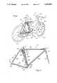
- FIG. 1is a perspective view of a bicycle incorporating the rear suspension linkage system constructed in accordance with the present invention
- FIG. 2is a side elevational view of the bicycle frame incorporating the rear suspension linkage system of the present invention
- FIG. 3is an enlarged perspective view of a portion of the rear suspension linkage system of the present invention.
- FIG. 4is an exploded view of the rear suspension linkage system shown in FIG. 3.
- FIG. 1perspectively illustrates a bicycle 10 incorporating a bicycle frame 12 constructed to incorporate the bicycle rear suspension and linkage system of the present invention.
- the bicycle frame 12generally comprises a head tube 14 disposed at the front end of the bicycle 10 and a seat tube 16 disposed toward the rear end of the bicycle 10.
- a stem 18Connected to the top end of the head tube 14 is a stem 18 to which is attached the handlebars 20.
- a conventional front shock absorber assembly 22Connected to the bottom end of the stem 18 is a conventional front shock absorber assembly 22 defining a first fork 24 and a second fork 26 between which is mounted the axle 28 of the front wheel 30.
- the front shock absorber assembly 22is adapted to provide the impressive first fork member 24 and compressive second fork member 26 with shock absorbing capability.
- Telescopically received into the top end of the seat tube 16is a seat post 32 having a saddle or seat 34 connected thereto.
- axle receiving bracket 38Rigidly attached to and extending between the head tube 14 and seat tube 16 is an elongate cross bar 36. Additionally, rigidly attached to the bottom end of the seat tube 16 is an axle receiving bracket 38 having an axle receiving bore 40 extending axially therethrough. In the preferred embodiment, the axle receiving bracket 38 has a generally cylindrical configuration and is attached to the lower end of the seat tube 16 via a brazed or welded connection. The bore 40 of the axle receiving bracket 38 is sized and configured to receive a bottom bracket axle of the bicycle 10. Attached to the opposed ends of the bottom bracket axle are first and second cranks 42 to which are attached pedals 44.
- a main sprocket 46which is adapted to rotate concurrently with the bottom bracket axle.
- a main sprocket 46Rigidly attached to and extending between the head tube 14 and the axle receiving bracket 38 is an elongate down tube 48.
- head tube 14, cross bar 36, axle receiving bracket 38, and down tube 48each have generally cylindrical configurations and are secured to one another via welded or braised connections.
- an upper pivot mount 50rigidly attached to the rear portion of the upper end of the seat tube 16 is an upper pivot mount 50. Additionally, rigidly attached to the lower portion of the axle receiving bracket 38 is a lower pivot mount 52.
- the upper pivot mount 50includes a pair of ear portions 54 defining a space therebetween. Extending laterally through the ear portions 54 are apertures 56 which are disposed in coaxial alignment. Additionally, extending through the lower pivot mount 52 is an aperture 58.
- the upper pivot mount 50 and lower pivot mount 52are attached to the seat tube 16 and axle receiving bracket 38, respectively, via a welding or brazing process.
- the upper rocker 60defines a front pair of mounting ears 64, a back pair of mounting ears 66, and an intermediate pair of mounting ears 68. Extending laterally through the front pair of mounting ears 64 are apertures 70 which are disposed in coaxial alignment, while extending laterally through the back pair of mounting ears 66 are apertures 72 which are also disposed in coaxial alignment. Additionally, extending laterally through the intermediate pair of mounting ears 68 are apertures 74 which are also disposed in coaxial alignment, although separated by the central portion of the upper rocker 60.
- the lower rocker 62defines a front pair of mounting ears 76 having a coaxially aligned pair of apertures 78 extending laterally therethrough, and a back pair of mounting ears 80 having a coaxially aligned pair of apertures 82 extending laterally therethrough.
- the upper rocker 60is pivotally connected to the upper pivot mount 50 via the receipt of the ear portions 54 of the upper pivot mount 50 into the space defined between the front pair of mounting ears 64 of the upper rocker 60.
- the distance separating the front pair of mounting ears 64is adapted to slidably accommodate the ear portions 54 of the upper pivot mount 50.
- the ear portions 54are oriented between the front pair of mounting ears 64 such that the pair of apertures 56 disposed between the ear portions 54 are coaxially aligned with the pair of apertures 70 disposed within the mounting ears 64.
- a fastener 84is inserted through the coaxially aligned apertures 56, 70 thus pivotally connecting the upper rocker 60 to the upper pivot mount 50.
- the lower pivot mount 52is received into the space defined between the front pair of mounting ears 76 of the lower rocker 62.
- the distance separating the mounting ears 76 from each otheris such that the lower pivot mount 52 may be slidably received therebetween.
- the lower pivot mount 52is oriented between the mounting ears 76 such that the pair of apertures 78 are coaxially aligned with the aperture 58 of the lower mount 52. Thereafter, as seen in FIG. 3, a fastener 86 is extended through the coaxially aligned apertures 78, 58, thus pivotally connecting the lower rocker 62 to the lower pivot mount 52.
- the bicycle frame 12 of the present inventionfurther comprises first and second seat stay members 88, 90 which have upper ends rigidly attached to a seat stay end housing 92.
- the seat stay end housing 92defines a bore 94 extending longitudinally therethrough, and is pivotally connected to the upper rocker 60.
- the seat stay end housing 92is received into the space defined between the back pair of mounting ears 66 of the upper rocker 60 which are spaced from each other a distance sufficient to allow the seat stay end housing 92 to be slidably received therebetween.
- the end housing 92is oriented between the mounting ears 66 such that the apertures 72 of the mounting ears 64 are coaxially aligned with the bore 94.
- a fastener 96is extended through the coaxially aligned apertures 72 and board 94, thus pivotally securing the end housing 92 to the upper rocker 60.
- the bicycle frame 12further includes first and second chain stay members 96, 98 which have front ends rigidly attached to a chain stay end housing 100.
- the chain stay end housing 100defines a bore 102 extending longitudinally therethrough and is pivotally connected to the lower pivot mount 52.
- the back pair of mounting ears 80 of the lower rocker 62are separated from each other a distance sufficient to allow the end housing 100 to be slidably received into the space defined between the mounting ears 80 in a manner wherein the apertures 82 of the mounting ears 80 are coaxially aligned with the bore 102 of the end housing 100.
- a fastener 104is inserted into the coaxially aligned apertures and bore 102, thus pivotally connecting the end housing 100 to the lower rocker 62.
- the upper ends of the seat stay members 88, 90 and the front ends of the chain stay members 96, 98are attached to their respective end housings 92, 100 via a welding or brazing process.
- the back ends of the chain stay members 96, 98are pivotally connected to the lower ends of the seat stay members 88, 90.
- the back end of the first chain stay member 96is pivotally connected to the lower end of the first seat stay member 88, with the back end of the second chain stay member 98 being pivotally connected to the lower end of the second seat stay member 90.
- Rigidly attached to the lower ends of the first and second seat stay members 88, 90is a pair of rear tire axle receiving members 106 which are adapted to support the rear tire axle 108 of the rear wheel 110 therebetween.
- Attached to one end of the rear tire axle 108is a rear sprocket 109 which is cooperatively engaged to the main sprocket 46 via a chain 111.
- the shock absorbercomprises a tubular body portion 114 having a reciprocable piston rod 116 extending axially from its top end, and a mounting bracket 118 attached to and extending downwardly from its bottom end.
- a portion of the outer surface of the body portion 114 adjacent the upper end thereofis threaded so as to allow a lower spring retention member 120 to be threadably received onto the body portion 114.
- rigidly attached to the distal end of the piston rod 116is an upper spring retention member 122 including an internally threaded stem 124 formed on the upper surface thereof.
- the shock absorber 112further comprises a helical spring member 130 disposed between the upper and lower spring retention members 120, 122, in a manner wherein the upper end of the spring member 130 abuts the lower surface of the upper spring retention member 122, the lower end of the spring member 130 abuts the top surface of the lower spring retention member 120, and the piston rod 116 of the shock absorber 112 extends axially through the center of the spring member 130.
- the tension of the spring member 130is selectively adjustable via the selective placement of the lower spring retention member 120 on the threaded outer surface portion of the body portion 114.
- the coupling member 126and hence the piston rod 116, is pivotally connected to the upper pivot mount 50.
- the coupling member 126is sized so as to be slidably receivable into the space defined between the ear portions 54 of the upper pivot mount 50 in a manner wherein the apertures 56 of the ear portions 54 are coaxially aligned with the aperture 128 of the coupling member 126.
- the upper rocker 60is also pivotally connected to the upper pivot mount 50 via the receipt of the fastener 84 into the coaxially aligned apertures 70 and 56.
- the fastener 84is utilized to pivotally interconnect the upper pivot mount 50 to the upper pivot mount 60 and coupling member 126 via the extension thereof through the coaxially aligned apertures 70, 56 and 128.
- the mounting bracket 118includes a hub 132 formed along the back vertical edge thereof and including an aperture 134 extending laterally therethrough.
- the bicycle frame 12further comprises first and second upper link rods 136, 138 which are used to pivotally connect the upper rocker 60 to the mounting bracket 118 of the shock absorber 112.
- the first and second upper link rods 136, 138are identically configured and include apertures 140 disposed in their upper ends, and apertures 132 disposed in their lower ends.
- the upper link rods 136, 138are sized such that the upper ends thereof are slidably receivable into respective spaces defined between the intermediate pair of mounting ears 68 and the main body portion of the upper rocker 60 in a manner wherein the apertures 140 disposed within the upper ends are coaxially aligned with the apertures 74 disposed within the mounting ears 68.
- a fastener 144is extended through the coaxially aligned apertures 74, 140 as well as an aperture (not shown) extending through the main body portion of the upper rocker 60 in coaxial alignment with the apertures 74, 140, thus pivotally connecting the upper link rods 136, 138 to the upper rocker 60.
- the bottom ends of the upper link rods 136, 138are then oriented over the opposed planar sides of the mounting bracket 118 such that the apertures 142 are coaxially aligned with the aperture 134 extending through the hub 132.
- a fastener 146is extended through the coaxially aligned apertures 142, 134 thus pivotally securing the lower ends of the upper link rods 136, 138 to the mounting bracket 118, and hence the shock absorber 112.
- the fastener 146is also extended between a pair of sleeves 148 which are sized and adapted to cover the exposed portions of the fastener 146 extending between the bottom ends of the upper link rods 36, 138 and mounting bracket 118.
- the sleeves 148each have a tubular configuration.
- the alignment rod 150Rigidly attached to and extending downwardly from the shock absorber 12, and more particularly the mounting bracket 118, is an elongate alignment rod 150.
- the upper end of the alignment rod 150is externally threaded so as to be threadably receivable into an internally threaded aperture (not shown) disposed within the bottom surface of the mounting bracket 118.
- the alignment rod aperture disposed in the bottom surface of the mounting bracket 118is oriented such that the alignment rod 150 is coaxially aligned with the piston rod 116 of the shock absorber 112 when threadably received thereinto.
- Formed on the lower end of the alignment rod 150is an enlarged head portion 152 which includes an aperture 154 extending laterally therethrough.
- the alignment rod 150is extended through and is guided by at least one, and preferably a pair of alignment bushings 156.
- Each of the alignment bushings 156are disposed within alignment brackets 158 which are rigidly attached to a rear portion of the seat tube 116 via a welding or brazing process.
- the threaded upper end of the alignment rod 150is extended upwardly through the lower and upper alignment bushings 156 in succession, prior to being threadably received into the alignment rod mounting aperture.
- Each of the alignment bushings 156includes an enlarged head portion overlying the top surface of a respective alignment bracket 158.
- the alignment rod 150 and piston rod 116which are coaxially aligned will also extend in generally parallel relation to the seat tube 116.
- the final component comprising the rear suspension linkage systemis a lower link rod 160 having a top end including an aperture 162 extending therethrough, and a bottom end having an aperture 164 extending therethrough.
- the top endis pivotally connected to the head portion 152 of the alignment rod 150 by coaxially aligning the apertures 162, 154 and extending a fastener 166 therethrough.
- the lower end of the lower link rod 160is pivotally connected to an extension 168 which is rigidly attached to and extends upwardly from a central portion of the chain stay and housing 100 and includes an aperture 170 extending therethrough.
- the pivotal connection between the lower link rod 160 and extension 168is facilitated by coaxially aligning the apertures 164, 170, and extending a fastener 172 therethrough.
- the rear axle of the rear wheelpivots about a single point which typically causes the pedaling forces to compress or extend the suspension and/or the rear wheel axle to move in a motion other than parallel to the direction of the force being applied to the rear wheel.
- the suspensionis affected by the pedal force, a portion of the rider's energy is wasted since such energy is used to needlessly activate the shock absorber of the rear suspension.
- efficiencyis lost if the rear tire axle moves in an arc that is not tangent to the direction of the shock force applied to the rear wheel, efficiency is lost.
- the various components comprising the rear suspension and linkage system of the present invention as previously describedare adapted to provide a suspension for the rear wheel 110 of the bicycle 10 that is negligibly affected by the pedaling force, and allows the rear axle 108 to move in a direction which is substantially parallel to the direction of the shock force exerted to the rear wheel 110 when such encounters a bump or other obstruction.
- the upward pulling of the upper link rods 136, 138also causes the alignment rod 150 to be pulled upwardly in the direction D through the alignment bushings 156, which in turn causes the lower link rod 160 to be pulled upwardly in the direction E.
- the upward pulling of the lower link rod 60 in the direction Ecauses the lower rocker 62 to pivot upwardly in the direction F.
- the concurrent upward pivoting of the upper rocker 60 in the direction B and the lower rocker 62 in the direction Fcauses the rear axle receiving brackets 106 and hence the rear axle 108 and rear tire 110 to move generally vertically upwardly in the direction G when subjected to a shock force, rather than moving in an arc which facilitates lost efficiency.
- the upper rocker 60 and seat stay members 88, 90 pivotally connected theretoare adapted to have a greater mechanical advantage on the connecting linkage comprising the shock absorber 112, upper link rods 136, 138, alignment rod 150 and lower link rod 160, then does the lower rocker 62 and pivotally connected chain stay members 96, 98.
- the adapting of the upper rocker 60 and seat stay members 88, 90 to possess the greater mechanical advantageserves to control the action of the remaining components of the linkage system and assures that the linkage assembly is nearly always in tension.
- the upward movement in the direction C of the upper link rods 136, 138 as caused by the upward pivotal movement in the direction B of the upper rocker 60is controlled and limited by the shock absorber 112.
- the shock absorber 112is adapted to dampen some of the shock force exerted on the rear tire 10 as such force is transmitted through the linkage assembly.
- the degree of the shock force absorbed by the shock absorber 112may be selectively adjusted via the positioning of the lower spring retention member 120 along the threaded outer surface portion of the body portion 114.
- the application of a shock force to the rear wheel 110tends to move the rear wheel 110 in the upward vertical direction G, and pivot the upper and lower rockers 60, 62 upwardly in the directions B, F.
- the upper and lower rockers 60, 62 and alignment rod 150are specifically oriented such that chain tension, occurring as a result of pedaling, tends to force the upper and lower rockers 60, 62 in opposite directions thereby producing pure tension in the alignment rod 150 and causing no influence in the vertical travel of the rear wheel 110 in the direction G.
- the chain 111tends to pull the rear sprocket 109 toward the front of the bicycle 10 in the direction H shown in FIG. 2.
- the pulling of the rear sprocket 109 in the direction Hcauses a force to be transmitted upwardly through the seat stay members 88, 90 in the direction A, and a force to be transmitted downwardly through the chain stay members 96, 98 in the direction I also shown in FIG. 2.
- the transmission of force in the direction Atends to pivot the upper rocker 60 upwardly in the direction B, while the transmission of force in the direction I tends to pivot the lower rocker 62 downwardly in a direction opposite the direction F, thus producing the tension in the alignment rod 150 as previously described.
- the rear wheel 110is free to accommodate vertical travel as a result of a vertical shock force despite the linkage assembly being under the effect of chain tension.
- the present linkage systemis fully active and can absorb bumps and shocks to identical degrees of efficiency regardless of the magnitude of chain tension, and will neither lock up or squat under the influence of pedaling.
Landscapes
- Engineering & Computer Science (AREA)
- Mechanical Engineering (AREA)
- Axle Suspensions And Sidecars For Cycles (AREA)
Abstract
Description
Claims (3)
Priority Applications (1)
| Application Number | Priority Date | Filing Date | Title |
|---|---|---|---|
| US08/087,998US5306036A (en) | 1993-01-13 | 1993-07-02 | Bicycle rear suspension |
Applications Claiming Priority (2)
| Application Number | Priority Date | Filing Date | Title |
|---|---|---|---|
| US08/004,131US5259637A (en) | 1993-01-13 | 1993-01-13 | Bicycle rear suspension |
| US08/087,998US5306036A (en) | 1993-01-13 | 1993-07-02 | Bicycle rear suspension |
Related Parent Applications (1)
| Application Number | Title | Priority Date | Filing Date |
|---|---|---|---|
| US08/004,131ContinuationUS5259637A (en) | 1993-01-13 | 1993-01-13 | Bicycle rear suspension |
Publications (1)
| Publication Number | Publication Date |
|---|---|
| US5306036Atrue US5306036A (en) | 1994-04-26 |
Family
ID=21709324
Family Applications (2)
| Application Number | Title | Priority Date | Filing Date |
|---|---|---|---|
| US08/004,131Expired - LifetimeUS5259637A (en) | 1993-01-13 | 1993-01-13 | Bicycle rear suspension |
| US08/087,998Expired - LifetimeUS5306036A (en) | 1993-01-13 | 1993-07-02 | Bicycle rear suspension |
Family Applications Before (1)
| Application Number | Title | Priority Date | Filing Date |
|---|---|---|---|
| US08/004,131Expired - LifetimeUS5259637A (en) | 1993-01-13 | 1993-01-13 | Bicycle rear suspension |
Country Status (1)
| Country | Link |
|---|---|
| US (2) | US5259637A (en) |
Cited By (58)
| Publication number | Priority date | Publication date | Assignee | Title |
|---|---|---|---|---|
| US5441292A (en)* | 1993-09-15 | 1995-08-15 | Gt Bicycles, Inc. | Bicycle rear suspension system |
| USD368880S (en) | 1994-09-09 | 1996-04-16 | Harrington Jeffrey M | Rear suspension portion of a bicycle frame |
| US5553881A (en)* | 1995-01-25 | 1996-09-10 | Outland Design Technologies, Inc. | Bicycle rear suspension system |
| US5628524A (en)* | 1995-01-25 | 1997-05-13 | Outland Design Techologies, Inc. | Bicycle wheel travel path for selectively applying chainstay lengthening effect and apparatus for providing same |
| US5797613A (en)* | 1996-06-14 | 1998-08-25 | Gt Bicycles, Inc. | Bicycle flex joint |
| WO1998056645A1 (en)* | 1997-06-10 | 1998-12-17 | Composites Liken Inc. | Bicycle rear suspension |
| US5901974A (en)* | 1996-09-04 | 1999-05-11 | Gt Bicycles, Inc. | Bicycle, anti-dive braking system |
| USD412868S (en) | 1996-07-24 | 1999-08-17 | Klein Bicycle Corporation | Downstrut for the swing arm of a suspension bicycle |
| US5947499A (en)* | 1996-06-14 | 1999-09-07 | Gt Bicycles, Inc. | Bicycle flexible joint |
| US5997022A (en)* | 1997-07-02 | 1999-12-07 | Shimano Inc. | Bicycle suspension assembly |
| US6029990A (en)* | 1997-05-13 | 2000-02-29 | Gt Bicycles, Inc. | Direct drive bicycle |
| US6036213A (en)* | 1997-12-01 | 2000-03-14 | Gt Bicycles, Inc. | Bicycle with shock absorbing rear assembly and common chain stay/shock absorber mounting bracket |
| US6073950A (en)* | 1997-10-28 | 2000-06-13 | Busby; James S. | Bicycle with crank assembly suspension system |
| US6076845A (en)* | 1998-09-24 | 2000-06-20 | Schwinn Cycling & Fitness Inc. | Rear suspension for a bicycle having a flexible chain stay |
| EP1010610A2 (en) | 1998-12-18 | 2000-06-21 | Shimano Inc. | Bicycle suspension |
| US6099010A (en)* | 1997-10-28 | 2000-08-08 | Gt Bicycles, Inc. | Bicycle with crank assembly suspension system |
| US6102421A (en)* | 1996-03-15 | 2000-08-15 | Schwinn Cycling & Fitness Inc. | Rear suspension for a bicycle |
| US6164676A (en)* | 1998-02-20 | 2000-12-26 | Trek Bicycle Corporation | Variable reduction cross-linkage for rear suspension bicycle |
| US6203042B1 (en) | 1998-02-20 | 2001-03-20 | Trek Bicycle Corporation | Bicycle rear suspension system providing relative rearward motion of rear axle |
| US6206397B1 (en) | 1995-01-25 | 2001-03-27 | James B. Klassen | Bicycle wheel travel path for selectively applying chainstay lengthening effect and apparatus for providing same |
| WO2001058748A1 (en)* | 2000-02-11 | 2001-08-16 | Maverick American Llc | Suspension system for a vehicle |
| US6378885B1 (en) | 1998-03-02 | 2002-04-30 | Anthony S. Ellsworth | Bicycle suspension apparatus and related method |
| US6386568B1 (en)* | 1997-04-25 | 2002-05-14 | Renault Sport | Bicycle rear suspension |
| US6439593B1 (en)* | 2001-07-09 | 2002-08-27 | Merida Industry Co., Ltd. | Rear shock absorbing assembly for a bicycle |
| US20040108682A1 (en)* | 2002-04-10 | 2004-06-10 | Ralf Malwitz | Twowheeler frame, in particular a bicycle frame |
| US20040238298A1 (en)* | 2003-04-28 | 2004-12-02 | Charles Nash | Multifunction braking and suspension device for a motorcycle or other vehicle |
| US20050067810A1 (en)* | 2003-09-25 | 2005-03-31 | David Weagle | Bicycle suspension systems |
| US20050167801A1 (en)* | 2004-02-04 | 2005-08-04 | Kerr Daniel C. | Structure and method for improved heat conduction for semiconductor devices |
| US20050184483A1 (en)* | 2003-12-12 | 2005-08-25 | Noel Buckley | Rear suspension system for bicycles |
| US20050285367A1 (en)* | 2004-06-29 | 2005-12-29 | Owen Chang | Bicycle rear suspension system |
| US20060022429A1 (en)* | 1998-03-02 | 2006-02-02 | Anthony S. Ellsworth | Bicycle suspension apparatus and related method |
| EP1661801A2 (en) | 2004-11-24 | 2006-05-31 | Shimano Inc. | Bicycle suspension assembly |
| US7066481B1 (en) | 2005-04-13 | 2006-06-27 | Felt Racing, Llc | Bicycle rear suspension |
| USRE39159E1 (en)* | 1995-01-25 | 2006-07-11 | Santa Cruz Bicycles, Inc. | Bicycle wheel travel path for selectively applying chainstay lengthening effect and apparatus for providing same |
| EP1698549A1 (en)* | 2005-03-02 | 2006-09-06 | Rocky Mountain Bicycles - a division of Groupe Procycle Inc. | Bicycle with rear suspension |
| US20060225942A1 (en)* | 2005-04-07 | 2006-10-12 | David Weagle | Vehicle suspension system for stable squat magnitude responses |
| US20080067772A1 (en)* | 2006-08-25 | 2008-03-20 | David Weagle | Vehicle suspension systems for seperated acceleration responses |
| US20080078602A1 (en)* | 2006-09-29 | 2008-04-03 | Honda Motor Co., Ltd. | Rear wheel suspension device of motorcycle |
| US20090001686A1 (en)* | 2007-06-28 | 2009-01-01 | Currie Christopher S | Rear wheel suspension system for a two-wheeled vehicle |
| US20090026728A1 (en)* | 2007-07-27 | 2009-01-29 | Niner, Inc. | Bicycle rear suspension |
| US7556276B1 (en)* | 2006-12-02 | 2009-07-07 | Charles E. Dunlap | Bicycle rear wheel suspension chassis |
| US20100102531A1 (en)* | 2005-11-14 | 2010-04-29 | Santa Cruz Bicycles, Inc. | Bicycle rear suspension system with controlled variable shock rate |
| US20100109282A1 (en)* | 2008-09-16 | 2010-05-06 | David Weagle | Bicycle suspension systems |
| US20100160099A1 (en)* | 2007-08-16 | 2010-06-24 | Trek Bicycle Corporation | Bicycle Derailleur System |
| US20110193316A1 (en)* | 2007-09-19 | 2011-08-11 | A-Pro Tech Co., Ltd. | Bicycle rear suspension system |
| US20110233892A1 (en)* | 2007-07-27 | 2011-09-29 | Niner, Inc. | Bicycle Rear Suspension |
| US20110291382A1 (en)* | 2008-10-09 | 2011-12-01 | Pierre-Geoffroy Plantet | Rear suspension for a two-wheel vehicle |
| US8272658B2 (en) | 2004-09-15 | 2012-09-25 | Yeti Cycling, Llc | Rear suspension system for a bicycle |
| US8882127B2 (en) | 2007-04-16 | 2014-11-11 | Trek Bicycle Corporation | Bicycle rear wheel suspension system |
| US9061729B2 (en) | 2012-08-09 | 2015-06-23 | Christopher Canfield | Suspension system for wheeled vehicles |
| US9561834B2 (en) | 2010-08-20 | 2017-02-07 | Yeti Cycling, Llc | Link suspension system |
| US9821879B2 (en) | 2010-08-20 | 2017-11-21 | Yeti Cycling, Llc | Reciprocating rail movement suspension system |
| US10766563B2 (en) | 2013-01-16 | 2020-09-08 | Yeti Cyclying, Llc | Rail suspension with integral shock and dampening mechanism |
| US10926830B2 (en) | 2017-07-07 | 2021-02-23 | Yeti Cycling, Llc | Vehicle suspension linkage |
| US11173983B2 (en) | 2017-03-17 | 2021-11-16 | Yeti Cycling, Llc | Vehicle suspension linkage |
| US12077241B2 (en) | 2019-02-01 | 2024-09-03 | Yeti Cycling, Llc | Multi-body vehicle suspension linkage |
| US12145684B2 (en) | 2019-12-24 | 2024-11-19 | Yeti Cycling, Llc | Constrained multiple instantaneous velocity center linkage assembly for vehicle suspension |
| US12384484B2 (en) | 2020-11-18 | 2025-08-12 | Yeti Cycling, Llc | Integrated motor mount and suspension pivot |
Families Citing this family (19)
| Publication number | Priority date | Publication date | Assignee | Title |
|---|---|---|---|---|
| US5409249A (en)* | 1993-09-15 | 1995-04-25 | Gt Bicycles, Inc. | Bicycle rear suspension system |
| US5452910A (en)* | 1994-09-09 | 1995-09-26 | Rockshox, Inc. | Rear wheel suspension for a bicycle and bicycle equipped therewith |
| USD372002S (en) | 1995-08-23 | 1996-07-23 | GT Bicycle, Inc. | Bicycle frame |
| US5803476A (en)* | 1995-08-25 | 1998-09-08 | Gt Bicycles, Inc. | Composite bicycle frame and method of manufacturing |
| US5649693A (en)* | 1995-08-25 | 1997-07-22 | Gt Bicycles, Inc. | Position sensitive friction damper |
| US5876054A (en)* | 1995-08-25 | 1999-03-02 | Gt Bicycles, Inc. | Composite bicycle frame and method of manufacture |
| US6264878B1 (en) | 1995-08-25 | 2001-07-24 | James S. Busby | Composite bicycle frame and method of manufacture |
| US5772228A (en)* | 1995-09-08 | 1998-06-30 | Beyond Beryllium Fabrications | Integrated rear suspension for a bicycle frame |
| DE19632345C2 (en)* | 1996-08-10 | 2000-01-13 | Fag Automobiltechnik Ag | Rolling bearings with speed measuring device |
| GB2352212A (en)* | 1999-07-21 | 2001-01-24 | Atb Sales Ltd | Rear wheel mounting in a bicycle |
| US6527289B2 (en)* | 2000-07-27 | 2003-03-04 | Greg M. Parigian | Rear suspension system for two-wheeled vehicles |
| US20060273545A1 (en)* | 2000-12-19 | 2006-12-07 | Parigian Greg M | Motorcycle rear suspension system |
| US6871867B2 (en)* | 2000-12-19 | 2005-03-29 | Greg M. Parigian | Multi-linking, rear suspension system for two-wheeled motor vehicles |
| FR2827831B1 (en) | 2001-07-26 | 2004-04-16 | Promiles | REAR SUSPENSION TWO WHEEL VEHICLE |
| FR2885345B1 (en)* | 2005-05-04 | 2007-07-20 | Look Cycle Internat Sa | CYCLE FRAME |
| US20070194550A1 (en)* | 2006-02-22 | 2007-08-23 | Frank Wadelton | Vehicle Wheel Suspension System |
| US8403350B2 (en) | 2010-05-14 | 2013-03-26 | Specialized Bicycle Components, Inc. | Seatstay suspension mount |
| DE112012000565T5 (en)* | 2011-01-25 | 2013-11-07 | M0Rpheus Cycles Llc | Bicycle frame with adjustable suspension components |
| JP2018034566A (en)* | 2016-08-29 | 2018-03-08 | 俊之 木森 | bicycle |
Citations (22)
| Publication number | Priority date | Publication date | Assignee | Title |
|---|---|---|---|---|
| US578615A (en)* | 1897-03-09 | Bicycle | ||
| US606323A (en)* | 1898-06-28 | wronski | ||
| US657667A (en)* | 1899-12-09 | 1900-09-11 | Virgel H Mills | Bicycle-frame. |
| US944795A (en)* | 1908-08-21 | 1909-12-28 | Edward H Leet | Frame for motor-cycles, bicycles, and the like. |
| US1047430A (en)* | 1912-01-09 | 1912-12-17 | Minneapolis Motor Company | Motor-cycle frame. |
| US1412012A (en)* | 1913-04-05 | 1922-04-04 | Bruno Carlo | Springing suspension device for cycles |
| GB220760A (en)* | 1923-06-21 | 1924-08-28 | Harry Topham Short | Improvements in or relating to the rear spring suspension of motor cycles, cycles and the like |
| US1594079A (en)* | 1925-01-28 | 1926-07-27 | Tanner William Mostyn | Resilient suspension means for motor cycles |
| US3917313A (en)* | 1973-12-17 | 1975-11-04 | Bultaco Compania Espanola Espa | Motorcycle suspension system |
| DE3033294A1 (en)* | 1979-09-12 | 1981-04-02 | Alberto Martorellas Barcelona Pous Quilez | BICYCLE |
| US4322088A (en)* | 1979-02-13 | 1982-03-30 | Honda Giken Kogyo Kabushiki Kaisha | Rear wheel suspension for a motorcycle |
| US4390095A (en)* | 1980-11-17 | 1983-06-28 | Grip-Pak, Inc. | Lay flat tube multi-packaging device for containers |
| US4506755A (en)* | 1981-12-11 | 1985-03-26 | Honda Motor Co Ltd | Rear suspension system for motorcycles |
| US4529056A (en)* | 1982-09-24 | 1985-07-16 | Ceske Zavody Motocyklove, Narodni Podnik | Mechanism for the spring-cushioning of a vehicle wheel |
| US4673053A (en)* | 1984-09-21 | 1987-06-16 | Honda Giken Kogyo Kabushiki Kaisha | Frame-rear suspension assembly for a motorcycle and the like |
| US4789174A (en)* | 1987-04-27 | 1988-12-06 | Mert Lawwill | Suspension bicycle |
| US4951791A (en)* | 1987-02-20 | 1990-08-28 | Belil Creixelli Jose L | Rear wheel suspension mechanism for motorcycles and the like vehicles |
| US4997197A (en)* | 1989-05-08 | 1991-03-05 | Shultz G Merle | Soft suspension bicycle |
| US5098114A (en)* | 1990-09-18 | 1992-03-24 | Jones Gwyndaf M | Pivotless human-powered vehicle suspension system |
| US5121937A (en)* | 1990-12-13 | 1992-06-16 | Mert Lawwill | Suspension bicycle |
| US5205572A (en)* | 1991-08-27 | 1993-04-27 | Schwinn Bicycle Company | Cycle rear suspension system |
| US5244224A (en)* | 1992-05-14 | 1993-09-14 | Gt Bicycles, Inc. | Rocker arm rear suspension bicycle |
- 1993
- 1993-01-13USUS08/004,131patent/US5259637A/ennot_activeExpired - Lifetime
- 1993-07-02USUS08/087,998patent/US5306036A/ennot_activeExpired - Lifetime
Patent Citations (22)
| Publication number | Priority date | Publication date | Assignee | Title |
|---|---|---|---|---|
| US578615A (en)* | 1897-03-09 | Bicycle | ||
| US606323A (en)* | 1898-06-28 | wronski | ||
| US657667A (en)* | 1899-12-09 | 1900-09-11 | Virgel H Mills | Bicycle-frame. |
| US944795A (en)* | 1908-08-21 | 1909-12-28 | Edward H Leet | Frame for motor-cycles, bicycles, and the like. |
| US1047430A (en)* | 1912-01-09 | 1912-12-17 | Minneapolis Motor Company | Motor-cycle frame. |
| US1412012A (en)* | 1913-04-05 | 1922-04-04 | Bruno Carlo | Springing suspension device for cycles |
| GB220760A (en)* | 1923-06-21 | 1924-08-28 | Harry Topham Short | Improvements in or relating to the rear spring suspension of motor cycles, cycles and the like |
| US1594079A (en)* | 1925-01-28 | 1926-07-27 | Tanner William Mostyn | Resilient suspension means for motor cycles |
| US3917313A (en)* | 1973-12-17 | 1975-11-04 | Bultaco Compania Espanola Espa | Motorcycle suspension system |
| US4322088A (en)* | 1979-02-13 | 1982-03-30 | Honda Giken Kogyo Kabushiki Kaisha | Rear wheel suspension for a motorcycle |
| DE3033294A1 (en)* | 1979-09-12 | 1981-04-02 | Alberto Martorellas Barcelona Pous Quilez | BICYCLE |
| US4390095A (en)* | 1980-11-17 | 1983-06-28 | Grip-Pak, Inc. | Lay flat tube multi-packaging device for containers |
| US4506755A (en)* | 1981-12-11 | 1985-03-26 | Honda Motor Co Ltd | Rear suspension system for motorcycles |
| US4529056A (en)* | 1982-09-24 | 1985-07-16 | Ceske Zavody Motocyklove, Narodni Podnik | Mechanism for the spring-cushioning of a vehicle wheel |
| US4673053A (en)* | 1984-09-21 | 1987-06-16 | Honda Giken Kogyo Kabushiki Kaisha | Frame-rear suspension assembly for a motorcycle and the like |
| US4951791A (en)* | 1987-02-20 | 1990-08-28 | Belil Creixelli Jose L | Rear wheel suspension mechanism for motorcycles and the like vehicles |
| US4789174A (en)* | 1987-04-27 | 1988-12-06 | Mert Lawwill | Suspension bicycle |
| US4997197A (en)* | 1989-05-08 | 1991-03-05 | Shultz G Merle | Soft suspension bicycle |
| US5098114A (en)* | 1990-09-18 | 1992-03-24 | Jones Gwyndaf M | Pivotless human-powered vehicle suspension system |
| US5121937A (en)* | 1990-12-13 | 1992-06-16 | Mert Lawwill | Suspension bicycle |
| US5205572A (en)* | 1991-08-27 | 1993-04-27 | Schwinn Bicycle Company | Cycle rear suspension system |
| US5244224A (en)* | 1992-05-14 | 1993-09-14 | Gt Bicycles, Inc. | Rocker arm rear suspension bicycle |
Non-Patent Citations (34)
| Title |
|---|
| 1992 Cannondale Spec Suspension Mountain Bicycles Article 10 pgs.* |
| 1992 Cannondale Spec-Suspension Mountain Bicycles-Article-10 pgs. |
| Bicycling, Nov. 1992, pp. 26 27, 58, 63 64, and 105.* |
| Bicycling, Nov. 1992, pp. 26-27, 58, 63-64, and 105. |
| Boulder Intrepid Al 2 pgs. Mountain Bike Action/Mar. 92.* |
| Boulder Intrepid Al-2 pgs.-Mountain Bike Action/Mar. '92. |
| Fisher RS 1 Article 4 pgs. Mountain Bike Action/Mar. 92.* |
| Fisher RS-1-Article-4 pgs.-Mountain Bike Action/Mar. '92. |
| Guide to Suspension and High Performance vol. 3 1992, pp. 9, 13 15, 17, 30 31, 36 37, 42 45, 47, 53, 60, 69, 71, 76, 85 87, 92, 96, 98, 100, 108 112, 117 and 119.* |
| Guide to Suspension and High Performance vol. 3 1992, pp. 9, 13-15, 17, 30-31, 36-37, 42-45, 47, 53, 60, 69, 71, 76, 85-87, '92, 96, 98, 100, 108-112, 117 and 119. |
| If The Best Motorcycle . . . "Litespeed Suspension", Mountain Bike-Jul. '9 8 pgs. |
| If The Best Motorcycle . . . Litespeed Suspension , Mountain Bike Jul. 9 8 pgs.* |
| Mountain Bike Action, Oct. 1992, pp. 10, 25 26, 28 29, 31, 36 37, 39 41, 44 45, 47, 58, 70, 73, 76, 79, 123, and 130.* |
| Mountain Bike Action, Oct. 1992, pp. 10, 25-26, 28-29, 31, 36-37, 39-41, 44 45, 47, 58, 70, 73, 76, 79, 123, and 130. |
| Mountain Biking Nov. 1992, vol. 6, No. 11, pp. 6 9, 25, 48 49, 65, 71, 73, 108 109, 115, 124, 129, 140, 143, 163 and 169.* |
| Mountain Biking Nov. 1992, vol. 6, No. 11, pp. 6-9, 25, 48-49, 65, 71, 73, 108-109, 115, 124, 129, 140, 143, 163 and 169. |
| Mountain Biking, Dec. 92, pp. 1 2, 5, 18, 44 49, 77, 127, and 160.* |
| Mountain Biking, Dec. '92, pp. 1-2, 5, 18, 44-49, 77, 127, and 160. |
| Mountain Biking, Jan. 93, vol. 7, No. 1, pp. 32 33, 40, 45, 71, 75, 82 83, 115 and 117.* |
| Mountain Biking, Jan. '93, vol. 7, No. 1, pp. 32-33, 40, 45, 71, 75, 82-83, 115 and 117. |
| Offroad Pro Flex 550 3 pgs. Offroad.* |
| Offroad Pro-Flex 550-3 pgs.-Offroad. |
| SCHWINN S.A.S.S. 7 pgs. Mountain Bike Action May 92.* |
| SCHWINN S.A.S.S.-7 pgs.-Mountain Bike Action-May '92. |
| Slingshot Mountain & City Biking, 6 pgs.* |
| Slingshot-Mountain & City Biking, 6 pgs. |
| Suspension Mania Strikes Cycling Mountain Bike Action/Feb. 92 3 pgs.* |
| Suspension Mania Strikes Cycling-Mountain Bike Action/Feb. '92 3 pgs. |
| Team Shockblok 6 pgs. Mountain Bike Action/Jul. 92.* |
| Team Shockblok-6 pgs.-Mountain Bike Action/Jul. '92. |
| Trek 9000 Series Spec This Beauty Is A Beast Article 8 pgs.* |
| Trek 9000 Series Spec-"This Beauty Is A Beast"-Article-8 pgs. |
| Welcome to the Next Generation . . . 9 pgs. Mountain Bike Jun. 92.* |
| Welcome to the Next Generation . . . --9 pgs.-Mountain Bike-Jun. '92. |
Cited By (114)
| Publication number | Priority date | Publication date | Assignee | Title |
|---|---|---|---|---|
| US5441292A (en)* | 1993-09-15 | 1995-08-15 | Gt Bicycles, Inc. | Bicycle rear suspension system |
| USD368880S (en) | 1994-09-09 | 1996-04-16 | Harrington Jeffrey M | Rear suspension portion of a bicycle frame |
| US5553881A (en)* | 1995-01-25 | 1996-09-10 | Outland Design Technologies, Inc. | Bicycle rear suspension system |
| US5628524A (en)* | 1995-01-25 | 1997-05-13 | Outland Design Techologies, Inc. | Bicycle wheel travel path for selectively applying chainstay lengthening effect and apparatus for providing same |
| USRE39159E1 (en)* | 1995-01-25 | 2006-07-11 | Santa Cruz Bicycles, Inc. | Bicycle wheel travel path for selectively applying chainstay lengthening effect and apparatus for providing same |
| US6206397B1 (en) | 1995-01-25 | 2001-03-27 | James B. Klassen | Bicycle wheel travel path for selectively applying chainstay lengthening effect and apparatus for providing same |
| US6488301B2 (en) | 1995-01-25 | 2002-12-03 | Santa Cruz Bicycles, Inc. | Bicycle wheel travel path for selectively applying chainstay lengthening effect and apparatus for providing same |
| US6102421A (en)* | 1996-03-15 | 2000-08-15 | Schwinn Cycling & Fitness Inc. | Rear suspension for a bicycle |
| US5797613A (en)* | 1996-06-14 | 1998-08-25 | Gt Bicycles, Inc. | Bicycle flex joint |
| US5865456A (en)* | 1996-06-14 | 1999-02-02 | Gt Bicycles, Inc. | Bicycle flex joint with non-torsional encasement |
| US5947499A (en)* | 1996-06-14 | 1999-09-07 | Gt Bicycles, Inc. | Bicycle flexible joint |
| USD412868S (en) | 1996-07-24 | 1999-08-17 | Klein Bicycle Corporation | Downstrut for the swing arm of a suspension bicycle |
| US6056307A (en)* | 1996-09-04 | 2000-05-02 | Busby; James S. | Bicycle anti-dive braking system |
| US5901974A (en)* | 1996-09-04 | 1999-05-11 | Gt Bicycles, Inc. | Bicycle, anti-dive braking system |
| US6386568B1 (en)* | 1997-04-25 | 2002-05-14 | Renault Sport | Bicycle rear suspension |
| US6029990A (en)* | 1997-05-13 | 2000-02-29 | Gt Bicycles, Inc. | Direct drive bicycle |
| US6155585A (en)* | 1997-05-13 | 2000-12-05 | Busby; James S. | Direct drive bicycle |
| US6079726A (en)* | 1997-05-13 | 2000-06-27 | Gt Bicycles, Inc. | Direct drive bicycle |
| WO1998056645A1 (en)* | 1997-06-10 | 1998-12-17 | Composites Liken Inc. | Bicycle rear suspension |
| US6450520B1 (en) | 1997-06-10 | 2002-09-17 | Mario Girard | Bicycle rear suspension |
| US5997022A (en)* | 1997-07-02 | 1999-12-07 | Shimano Inc. | Bicycle suspension assembly |
| US6099010A (en)* | 1997-10-28 | 2000-08-08 | Gt Bicycles, Inc. | Bicycle with crank assembly suspension system |
| US6073950A (en)* | 1997-10-28 | 2000-06-13 | Busby; James S. | Bicycle with crank assembly suspension system |
| US6036213A (en)* | 1997-12-01 | 2000-03-14 | Gt Bicycles, Inc. | Bicycle with shock absorbing rear assembly and common chain stay/shock absorber mounting bracket |
| US6164676A (en)* | 1998-02-20 | 2000-12-26 | Trek Bicycle Corporation | Variable reduction cross-linkage for rear suspension bicycle |
| US6203042B1 (en) | 1998-02-20 | 2001-03-20 | Trek Bicycle Corporation | Bicycle rear suspension system providing relative rearward motion of rear axle |
| US20040145149A1 (en)* | 1998-03-02 | 2004-07-29 | Anthony S. Ellsworth | Bicycle suspension apparatus and related method |
| US6378885B1 (en) | 1998-03-02 | 2002-04-30 | Anthony S. Ellsworth | Bicycle suspension apparatus and related method |
| US6926298B2 (en) | 1998-03-02 | 2005-08-09 | Anthony S. Ellsworth | Bicycle suspension apparatus and related method |
| US20060022429A1 (en)* | 1998-03-02 | 2006-02-02 | Anthony S. Ellsworth | Bicycle suspension apparatus and related method |
| US6471230B2 (en) | 1998-03-02 | 2002-10-29 | Anthony S. Ellsworth | Bicycle suspension apparatus and related method |
| US6595538B2 (en) | 1998-03-02 | 2003-07-22 | Anthony S. Ellsworth | Bicycle suspension apparatus and related method |
| US7296815B2 (en) | 1998-03-02 | 2007-11-20 | Anthony S. Ellsworth | Bicycle suspension apparatus and related method |
| US6076845A (en)* | 1998-09-24 | 2000-06-20 | Schwinn Cycling & Fitness Inc. | Rear suspension for a bicycle having a flexible chain stay |
| US6149175A (en)* | 1998-12-18 | 2000-11-21 | Shimano Inc. | Bicycle suspension |
| EP1010610A2 (en) | 1998-12-18 | 2000-06-21 | Shimano Inc. | Bicycle suspension |
| US20030011167A1 (en)* | 2000-02-11 | 2003-01-16 | Maverick American Llc | Suspension system for a vehicle |
| US6854753B2 (en)* | 2000-02-11 | 2005-02-15 | Maverick American Llc | Suspension system for a vehicle |
| WO2001058748A1 (en)* | 2000-02-11 | 2001-08-16 | Maverick American Llc | Suspension system for a vehicle |
| US6450521B1 (en)* | 2000-02-11 | 2002-09-17 | Maverick American Llc | Suspension system for a vehicle |
| US6439593B1 (en)* | 2001-07-09 | 2002-08-27 | Merida Industry Co., Ltd. | Rear shock absorbing assembly for a bicycle |
| US6840528B2 (en)* | 2002-04-10 | 2005-01-11 | Derby Cycle Werke Gmbh | Two wheeler frame, in particular a bicycle frame |
| US20040108682A1 (en)* | 2002-04-10 | 2004-06-10 | Ralf Malwitz | Twowheeler frame, in particular a bicycle frame |
| US20040238298A1 (en)* | 2003-04-28 | 2004-12-02 | Charles Nash | Multifunction braking and suspension device for a motorcycle or other vehicle |
| US20070024022A1 (en)* | 2003-09-25 | 2007-02-01 | David Weagle | Vehicle suspension systems |
| US20110115181A1 (en)* | 2003-09-25 | 2011-05-19 | David Weagle | Vehicle suspension systems |
| US20050067810A1 (en)* | 2003-09-25 | 2005-03-31 | David Weagle | Bicycle suspension systems |
| US7048292B2 (en) | 2003-09-25 | 2006-05-23 | David Weagle | Bicycle suspension systems |
| US20050067806A1 (en)* | 2003-09-25 | 2005-03-31 | David Weagle | Vehicle suspension systems |
| US20060119070A1 (en)* | 2003-09-25 | 2006-06-08 | David Weagle | Bicycle suspension systems |
| US7128329B2 (en) | 2003-09-25 | 2006-10-31 | David Weagle | Vehicle suspension systems |
| US7828314B2 (en) | 2003-09-25 | 2010-11-09 | Dw-Link Incorporated | Vehicle suspension systems |
| US7980579B2 (en) | 2003-12-12 | 2011-07-19 | Noel Buckley | Rear suspension system for bicycles |
| US8646797B2 (en) | 2003-12-12 | 2014-02-11 | Noel Buckley | Rear suspension system for bicycles |
| US10363988B2 (en) | 2003-12-12 | 2019-07-30 | 668598 B.C. Ltd. | Rear suspension system for bicycles |
| US20110233893A1 (en)* | 2003-12-12 | 2011-09-29 | Noel Buckley | Rear suspension system for bicycles |
| US20050184483A1 (en)* | 2003-12-12 | 2005-08-25 | Noel Buckley | Rear suspension system for bicycles |
| US11919602B2 (en) | 2003-12-12 | 2024-03-05 | Knolly Bikes, Inc. | Rear suspension system for bicycles |
| US11845510B2 (en) | 2003-12-12 | 2023-12-19 | Knolly Bikes, Inc. | Rear suspension system for bicycles |
| US11312447B2 (en) | 2003-12-12 | 2022-04-26 | Knolly Bikes, Inc. | Rear suspension system for bicycles |
| US20080258427A1 (en)* | 2003-12-12 | 2008-10-23 | Noel Buckley | Rear suspension system for bicycles |
| US7467803B2 (en) | 2003-12-12 | 2008-12-23 | Noel Buckley | Rear suspension system for bicycles |
| US20050167801A1 (en)* | 2004-02-04 | 2005-08-04 | Kerr Daniel C. | Structure and method for improved heat conduction for semiconductor devices |
| US20050285367A1 (en)* | 2004-06-29 | 2005-12-29 | Owen Chang | Bicycle rear suspension system |
| US7566066B2 (en)* | 2004-06-29 | 2009-07-28 | Giant Manufacturing Co., Ltd. | Bicycle rear suspension system |
| US8696008B2 (en) | 2004-09-15 | 2014-04-15 | Yeti Cycling, Llc | Rear suspension system for a bicycle |
| US10293881B2 (en) | 2004-09-15 | 2019-05-21 | Yeti Cycling, Llc | Rear suspension system for a bicycle |
| US9221513B2 (en) | 2004-09-15 | 2015-12-29 | Yeti Cycling, Llc | Rear suspension system for a bicycle |
| US8272658B2 (en) | 2004-09-15 | 2012-09-25 | Yeti Cycling, Llc | Rear suspension system for a bicycle |
| US7222870B2 (en) | 2004-11-24 | 2007-05-29 | Shimano Inc. | Bicycle suspension assembly |
| EP1661801A2 (en) | 2004-11-24 | 2006-05-31 | Shimano Inc. | Bicycle suspension assembly |
| US20060197306A1 (en)* | 2005-03-02 | 2006-09-07 | Rocky Mountain Bicycles - A Division Of Procycle Group Inc. | Bicycle with rear suspension |
| US7216883B2 (en) | 2005-03-02 | 2007-05-15 | Rocky Mountain Bicycles-A Division Of Procycle Group Inc. | Bicycle with rear suspension |
| EP1698549A1 (en)* | 2005-03-02 | 2006-09-06 | Rocky Mountain Bicycles - a division of Groupe Procycle Inc. | Bicycle with rear suspension |
| US20060225942A1 (en)* | 2005-04-07 | 2006-10-12 | David Weagle | Vehicle suspension system for stable squat magnitude responses |
| US7661503B2 (en) | 2005-04-07 | 2010-02-16 | Orion Dynamics, Inc. | Vehicle suspension system for stable squat magnitude responses |
| US7066481B1 (en) | 2005-04-13 | 2006-06-27 | Felt Racing, Llc | Bicycle rear suspension |
| US8641072B2 (en) | 2005-11-14 | 2014-02-04 | Santa Cruz Bicycles, Inc. | Bicycle rear suspension system with controlled variable shock rate |
| US8733774B2 (en) | 2005-11-14 | 2014-05-27 | Santa Cruz Bicycles, Inc. | Bicycle rear suspension system with controlled variable shock rate |
| US20100102531A1 (en)* | 2005-11-14 | 2010-04-29 | Santa Cruz Bicycles, Inc. | Bicycle rear suspension system with controlled variable shock rate |
| US8272657B2 (en) | 2005-11-14 | 2012-09-25 | Santa Cruz Bicycles, Inc. | Bicycle rear suspension system with controlled variable shock rate |
| US8002301B2 (en) | 2006-08-25 | 2011-08-23 | Split Pivot, Inc. | Vehicle suspension systems for seperated acceleration responses |
| US20080073868A1 (en)* | 2006-08-25 | 2008-03-27 | David Weagle | Vehicle suspension systems for seperated acceleration responses |
| US20080067772A1 (en)* | 2006-08-25 | 2008-03-20 | David Weagle | Vehicle suspension systems for seperated acceleration responses |
| US7717212B2 (en) | 2006-08-25 | 2010-05-18 | Split Pivot, Inc. | Vehicle suspension systems for seperated acceleration responses |
| US8496083B2 (en)* | 2006-09-29 | 2013-07-30 | Honda Motor Co., Ltd. | Rear wheel suspension device of motorcycle |
| US20080078602A1 (en)* | 2006-09-29 | 2008-04-03 | Honda Motor Co., Ltd. | Rear wheel suspension device of motorcycle |
| US7556276B1 (en)* | 2006-12-02 | 2009-07-07 | Charles E. Dunlap | Bicycle rear wheel suspension chassis |
| US8882127B2 (en) | 2007-04-16 | 2014-11-11 | Trek Bicycle Corporation | Bicycle rear wheel suspension system |
| US20090001686A1 (en)* | 2007-06-28 | 2009-01-01 | Currie Christopher S | Rear wheel suspension system for a two-wheeled vehicle |
| US7815207B2 (en) | 2007-06-28 | 2010-10-19 | Currie Christopher S | Rear wheel suspension system for a two-wheeled vehicle |
| US20090026728A1 (en)* | 2007-07-27 | 2009-01-29 | Niner, Inc. | Bicycle rear suspension |
| US20110233892A1 (en)* | 2007-07-27 | 2011-09-29 | Niner, Inc. | Bicycle Rear Suspension |
| US8590914B2 (en) | 2007-07-27 | 2013-11-26 | Niner, Inc. | Bicycle rear suspension |
| US7934739B2 (en) | 2007-07-27 | 2011-05-03 | Niner, Inc. | Bicycle rear suspension |
| US20100160099A1 (en)* | 2007-08-16 | 2010-06-24 | Trek Bicycle Corporation | Bicycle Derailleur System |
| US20110193316A1 (en)* | 2007-09-19 | 2011-08-11 | A-Pro Tech Co., Ltd. | Bicycle rear suspension system |
| US20100109282A1 (en)* | 2008-09-16 | 2010-05-06 | David Weagle | Bicycle suspension systems |
| US20110291382A1 (en)* | 2008-10-09 | 2011-12-01 | Pierre-Geoffroy Plantet | Rear suspension for a two-wheel vehicle |
| US9821879B2 (en) | 2010-08-20 | 2017-11-21 | Yeti Cycling, Llc | Reciprocating rail movement suspension system |
| US10343742B2 (en) | 2010-08-20 | 2019-07-09 | Yeti Cycling, Llc | Link suspension system |
| US9561834B2 (en) | 2010-08-20 | 2017-02-07 | Yeti Cycling, Llc | Link suspension system |
| US10822048B2 (en) | 2010-08-20 | 2020-11-03 | Yeti Cycling, Llc | Reciprocating rail movement suspension system |
| US12077243B2 (en) | 2010-08-20 | 2024-09-03 | Yeti Cycling, Llc | Reciprocating rail movement suspension system |
| US11485447B2 (en) | 2010-08-20 | 2022-11-01 | Yeti Cycling, Llc | Reciprocating rail movement suspension system |
| US9061729B2 (en) | 2012-08-09 | 2015-06-23 | Christopher Canfield | Suspension system for wheeled vehicles |
| US10766563B2 (en) | 2013-01-16 | 2020-09-08 | Yeti Cyclying, Llc | Rail suspension with integral shock and dampening mechanism |
| US11173983B2 (en) | 2017-03-17 | 2021-11-16 | Yeti Cycling, Llc | Vehicle suspension linkage |
| US10926830B2 (en) | 2017-07-07 | 2021-02-23 | Yeti Cycling, Llc | Vehicle suspension linkage |
| USD1023842S1 (en) | 2017-07-07 | 2024-04-23 | Yeti Cycling, Llc | Shock extension |
| US12344347B2 (en) | 2017-07-07 | 2025-07-01 | Yeti Cycling, Llc | Vehicle suspension linkage |
| US12077241B2 (en) | 2019-02-01 | 2024-09-03 | Yeti Cycling, Llc | Multi-body vehicle suspension linkage |
| US12145684B2 (en) | 2019-12-24 | 2024-11-19 | Yeti Cycling, Llc | Constrained multiple instantaneous velocity center linkage assembly for vehicle suspension |
| US12384484B2 (en) | 2020-11-18 | 2025-08-12 | Yeti Cycling, Llc | Integrated motor mount and suspension pivot |
Also Published As
| Publication number | Publication date |
|---|---|
| US5259637A (en) | 1993-11-09 |
Similar Documents
| Publication | Publication Date | Title |
|---|---|---|
| US5306036A (en) | Bicycle rear suspension | |
| US5244224A (en) | Rocker arm rear suspension bicycle | |
| US5409249A (en) | Bicycle rear suspension system | |
| CA2335953C (en) | Bicycle with crank assembly suspension system | |
| US5441292A (en) | Bicycle rear suspension system | |
| US8033558B2 (en) | Bicycle rear suspension system | |
| US6843494B2 (en) | Rear suspension system for two-wheeled vehicles, particularly bicycles | |
| US8434776B2 (en) | Bicycle frame with rear suspension system | |
| US6056307A (en) | Bicycle anti-dive braking system | |
| US5284354A (en) | Bicycle suspension system | |
| US6029990A (en) | Direct drive bicycle | |
| US5749590A (en) | Suspension fork assembly | |
| US4548421A (en) | Recumbent vehicle | |
| US6073950A (en) | Bicycle with crank assembly suspension system | |
| US6581950B1 (en) | Single pivot bicycle suspension apparatus and related methods | |
| US5725227A (en) | Suspension system for a bicycle | |
| US5269552A (en) | Bicycle frame composition | |
| US6036213A (en) | Bicycle with shock absorbing rear assembly and common chain stay/shock absorber mounting bracket | |
| US6206396B1 (en) | Cycle incorporating shock absorber | |
| US6164676A (en) | Variable reduction cross-linkage for rear suspension bicycle | |
| US7296815B2 (en) | Bicycle suspension apparatus and related method | |
| US20040061305A1 (en) | Rear wheel suspension system for a bicycle |
Legal Events
| Date | Code | Title | Description |
|---|---|---|---|
| AS | Assignment | Owner name:GT BICYCLES, INC., CALIFORNIA Free format text:ASSIGNMENT OF ASSIGNORS INTEREST;ASSIGNOR:BUSBY, JAMES S.;REEL/FRAME:006719/0456 Effective date:19921230 | |
| AS | Assignment | Owner name:JACKSON NATIONAL LIFE INSURANCE COMPANY, AS SUBORD Free format text:SECURITY INTEREST;ASSIGNOR:GT BICYLES, INC.;REEL/FRAME:006804/0676 Effective date:19931112 | |
| AS | Assignment | Owner name:BANK OF AMERICA NATIONAL TRUST AND SAVINGS ASSOCIA Free format text:SECURITY AGREEMENT;ASSIGNOR:GT BICYCLES CALIFORNIA, INC.;REEL/FRAME:007803/0598 Effective date:19951129 | |
| AS | Assignment | Owner name:BANK OF AMERICA NATIONAL TRUST AND SAVINGS ASSOCIA Free format text:ASSIGNMENT OF ASSIGNORS INTEREST;ASSIGNOR:GT BICYCLES CALIFORNIA, INC.;REEL/FRAME:007894/0857 Effective date:19951129 | |
| FEPP | Fee payment procedure | Free format text:PAYOR NUMBER ASSIGNED (ORIGINAL EVENT CODE: ASPN); ENTITY STATUS OF PATENT OWNER: LARGE ENTITY Free format text:PAT HLDR NO LONGER CLAIMS SMALL ENT STAT AS SMALL BUSINESS (ORIGINAL EVENT CODE: LSM2); ENTITY STATUS OF PATENT OWNER: LARGE ENTITY | |
| FPAY | Fee payment | Year of fee payment:4 | |
| AS | Assignment | Owner name:BANKAMERICA BUSINESS CREDIT, INC., CALIFORNIA Free format text:SUPPLEMENTAL SECURITY;ASSIGNOR:GT BICYCLES, INC.;REEL/FRAME:009197/0652 Effective date:19980429 | |
| AS | Assignment | Owner name:COMERICA BANK, AS AGENT, A MICHIGAN CORPORATION, M Free format text:SECURITY AGREEMENT;ASSIGNOR:GT BICYCLES, INC., A DELAWARE CORPORATION;REEL/FRAME:009875/0282 Effective date:19980930 | |
| AS | Assignment | Owner name:GMAC BUSINESS CREDIT, LLC, ILLINOIS Free format text:SECURITY INTEREST;ASSIGNOR:SCHWINN ACQUISITION, LLC;REEL/FRAME:012166/0310 Effective date:20010920 | |
| REMI | Maintenance fee reminder mailed | ||
| FPAY | Fee payment | Year of fee payment:8 | |
| SULP | Surcharge for late payment | Year of fee payment:7 | |
| STCF | Information on status: patent grant | Free format text:PATENTED CASE | |
| FP | Lapsed due to failure to pay maintenance fee | Effective date:20020426 | |
| FEPP | Fee payment procedure | Free format text:PAT HOLDER CLAIMS SMALL ENTITY STATUS, ENTITY STATUS SET TO SMALL (ORIGINAL EVENT CODE: LTOS); ENTITY STATUS OF PATENT OWNER: LARGE ENTITY | |
| AS | Assignment | Owner name:SCHWIN ACQUISITION, LLC, WISCONSIN Free format text:ASSIGNMENT OF ASSIGNORS INTEREST;ASSIGNORS:SCHWINN CYCLING & FITNESS, INC;GT BICYCLE, INC.;REEL/FRAME:014926/0571 Effective date:20040802 | |
| FEPP | Fee payment procedure | Free format text:PAT HOLDER NO LONGER CLAIMS SMALL ENTITY STATUS, ENTITY STATUS SET TO UNDISCOUNTED (ORIGINAL EVENT CODE: STOL); ENTITY STATUS OF PATENT OWNER: LARGE ENTITY | |
| FPAY | Fee payment | Year of fee payment:12 |