US5305405A - Patch cord - Google Patents
Patch cordDownload PDFInfo
- Publication number
- US5305405A US5305405AUS08/017,156US1715693AUS5305405AUS 5305405 AUS5305405 AUS 5305405AUS 1715693 AUS1715693 AUS 1715693AUS 5305405 AUS5305405 AUS 5305405A
- Authority
- US
- United States
- Prior art keywords
- cable
- signal
- energy
- light
- receiving
- Prior art date
- Legal status (The legal status is an assumption and is not a legal conclusion. Google has not performed a legal analysis and makes no representation as to the accuracy of the status listed.)
- Expired - Lifetime
Links
- 230000008878couplingEffects0.000claimsabstractdescription99
- 238000010168coupling processMethods0.000claimsabstractdescription99
- 238000005859coupling reactionMethods0.000claimsabstractdescription99
- 230000005540biological transmissionEffects0.000claimsabstractdescription80
- 208000032369Primary transmissionDiseases0.000claimsabstractdescription30
- 230000004044responseEffects0.000claimsabstractdescription13
- 230000001681protective effectEffects0.000claimsabstractdescription8
- 239000000835fiberSubstances0.000claimsdescription92
- 239000013307optical fiberSubstances0.000claimsdescription27
- 239000000700radioactive tracerSubstances0.000claimsdescription21
- 230000003287optical effectEffects0.000claimsdescription17
- 208000032370Secondary transmissionDiseases0.000claimsdescription15
- 230000008054signal transmissionEffects0.000claims3
- 241000270281Coluber constrictorSpecies0.000claims1
- OQZCSNDVOWYALR-UHFFFAOYSA-NflurochloridoneChemical compoundFC(F)(F)C1=CC=CC(N2C(C(Cl)C(CCl)C2)=O)=C1OQZCSNDVOWYALR-UHFFFAOYSA-N0.000claims1
- 239000012780transparent materialSubstances0.000claims1
- 229920000271Kevlar®Polymers0.000description7
- 238000009434installationMethods0.000description7
- 239000004761kevlarSubstances0.000description7
- 238000005286illuminationMethods0.000description4
- 239000000463materialSubstances0.000description4
- 229920003023plasticPolymers0.000description4
- 230000000007visual effectEffects0.000description4
- RYGMFSIKBFXOCR-UHFFFAOYSA-NCopperChemical group[Cu]RYGMFSIKBFXOCR-UHFFFAOYSA-N0.000description3
- 230000001154acute effectEffects0.000description3
- 239000004020conductorSubstances0.000description3
- 238000010276constructionMethods0.000description3
- 238000005728strengtheningMethods0.000description3
- 238000004891communicationMethods0.000description2
- 229910052802copperInorganic materials0.000description2
- 239000010949copperSubstances0.000description2
- 230000004048modificationEffects0.000description2
- 238000012986modificationMethods0.000description2
- 239000004033plasticSubstances0.000description2
- 238000004513sizingMethods0.000description2
- NIXOWILDQLNWCW-UHFFFAOYSA-Nacrylic acid groupChemical groupC(C=C)(=O)ONIXOWILDQLNWCW-UHFFFAOYSA-N0.000description1
- 230000004913activationEffects0.000description1
- 239000000853adhesiveSubstances0.000description1
- 230000001070adhesive effectEffects0.000description1
- 230000002411adverseEffects0.000description1
- 230000000694effectsEffects0.000description1
- 229920002457flexible plasticPolymers0.000description1
- 238000002347injectionMethods0.000description1
- 239000007924injectionSubstances0.000description1
- 230000007246mechanismEffects0.000description1
- 238000000034methodMethods0.000description1
- 239000002991molded plasticSubstances0.000description1
- 239000004417polycarbonateSubstances0.000description1
- 229920000515polycarbonatePolymers0.000description1
- 239000007787solidSubstances0.000description1
Images


Classifications
- G—PHYSICS
- G02—OPTICS
- G02B—OPTICAL ELEMENTS, SYSTEMS OR APPARATUS
- G02B6/00—Light guides; Structural details of arrangements comprising light guides and other optical elements, e.g. couplings
- G02B6/24—Coupling light guides
- G02B6/26—Optical coupling means
- G02B6/28—Optical coupling means having data bus means, i.e. plural waveguides interconnected and providing an inherently bidirectional system by mixing and splitting signals
- G02B6/2804—Optical coupling means having data bus means, i.e. plural waveguides interconnected and providing an inherently bidirectional system by mixing and splitting signals forming multipart couplers without wavelength selective elements, e.g. "T" couplers, star couplers
- G02B6/2852—Optical coupling means having data bus means, i.e. plural waveguides interconnected and providing an inherently bidirectional system by mixing and splitting signals forming multipart couplers without wavelength selective elements, e.g. "T" couplers, star couplers using tapping light guides arranged sidewardly, e.g. in a non-parallel relationship with respect to the bus light guides (light extraction or launching through cladding, with or without surface discontinuities, bent structures)
- G—PHYSICS
- G02—OPTICS
- G02B—OPTICAL ELEMENTS, SYSTEMS OR APPARATUS
- G02B6/00—Light guides; Structural details of arrangements comprising light guides and other optical elements, e.g. couplings
- G02B6/24—Coupling light guides
- G02B6/26—Optical coupling means
- G02B6/28—Optical coupling means having data bus means, i.e. plural waveguides interconnected and providing an inherently bidirectional system by mixing and splitting signals
- G02B6/2804—Optical coupling means having data bus means, i.e. plural waveguides interconnected and providing an inherently bidirectional system by mixing and splitting signals forming multipart couplers without wavelength selective elements, e.g. "T" couplers, star couplers
- G02B6/2817—Optical coupling means having data bus means, i.e. plural waveguides interconnected and providing an inherently bidirectional system by mixing and splitting signals forming multipart couplers without wavelength selective elements, e.g. "T" couplers, star couplers using reflective elements to split or combine optical signals
- G—PHYSICS
- G02—OPTICS
- G02B—OPTICAL ELEMENTS, SYSTEMS OR APPARATUS
- G02B6/00—Light guides; Structural details of arrangements comprising light guides and other optical elements, e.g. couplings
- G02B6/24—Coupling light guides
- G02B6/42—Coupling light guides with opto-electronic elements
- G02B6/4201—Packages, e.g. shape, construction, internal or external details
- G02B6/4219—Mechanical fixtures for holding or positioning the elements relative to each other in the couplings; Alignment methods for the elements, e.g. measuring or observing methods especially used therefor
- G02B6/4236—Fixing or mounting methods of the aligned elements
- G02B6/424—Mounting of the optical light guide
- G—PHYSICS
- G02—OPTICS
- G02B—OPTICAL ELEMENTS, SYSTEMS OR APPARATUS
- G02B6/00—Light guides; Structural details of arrangements comprising light guides and other optical elements, e.g. couplings
- G02B6/24—Coupling light guides
- G02B6/42—Coupling light guides with opto-electronic elements
- G02B6/4201—Packages, e.g. shape, construction, internal or external details
- G02B6/4287—Optical modules with tapping or launching means through the surface of the waveguide
- Y—GENERAL TAGGING OF NEW TECHNOLOGICAL DEVELOPMENTS; GENERAL TAGGING OF CROSS-SECTIONAL TECHNOLOGIES SPANNING OVER SEVERAL SECTIONS OF THE IPC; TECHNICAL SUBJECTS COVERED BY FORMER USPC CROSS-REFERENCE ART COLLECTIONS [XRACs] AND DIGESTS
- Y10—TECHNICAL SUBJECTS COVERED BY FORMER USPC
- Y10S—TECHNICAL SUBJECTS COVERED BY FORMER USPC CROSS-REFERENCE ART COLLECTIONS [XRACs] AND DIGESTS
- Y10S385/00—Optical waveguides
- Y10S385/901—Illuminating or display apparatus
Definitions
- This inventionpertains to patch cords for the telecommunications industry. More particularly, this invention pertains to a patch cord which carries means for providing a visual indicator.
- patch cordsare widely used to connect various pieces of equipment.
- a patch cordmay be used to extend between two jack fields.
- patch cords made of coaxial cablesare used. The ends of the patch cords are provided with plugs which are received within jacks contained in the two jack fields.
- telecommunications facilitiessuch as central office locations
- patch cordsextending between various pieces of equipment.
- a technicianmust determine quickly and accurately the two pieces of equipment which are connected by a single patch cord.
- tracer lampshave been used in the past.
- a tracer lamp systemincludes two flashing or non-flashing LED's each physically attached to the two pieces of equipment being connected by the patch cord.
- the patch cordcommonly carries an extra conductor or pair of conductors terminating at pins on opposite ends of the patch cord.
- the equipment being connectedwould have pin jacks for receiving the pins. Accordingly, the plugs of the coaxial cable are inserted within jacks contained in the two jack fields. The tracer lamp pins are then inserted into the pin jacks associated with the two jack fields.
- LED's on each of the two pieces of equipmentare illuminated with the LED's being connected by the extra conductor carried on the coaxial cable.
- a patch cordhaving a transmission element extending from a first cable end to a second cable end.
- An energy transmission elementis carried on the cable and extends from a first end approximate the first cable end to a second end approximate the second cable end.
- a first connectoris secured to the first cable end and a second connector is secured to the second cable end.
- First and second couplingsare connected to the first end and the second end, respectively, of the energy transmission member.
- the first couplingincludes means for receiving energy from an external source and transmitting the energy along the energy transmission member to the second coupling.
- the second couplingincludes second means for receiving the energy from the energy transmission member and generating a visible signal in response to receiving the energy.
- FIG. 1is a perspective schematic of a patch cord according to the present invention
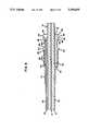
- FIG. 2is a cross-sectional view of one embodiment of a cable of the patch cord
- FIG. 3is a cross-sectional view of a second embodiment of a cable of the patch cord
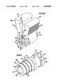
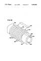
- FIG. 4is a perspective view of a coupling for use with the present invention.
- FIG. 5is a side elevation view of the coupling of FIG. 4;
- FIG. 6is an end view of the coupling of FIG. 4;
- FIG. 7is a view taken along line 7--7 of FIG. 5;
- FIG. 8is a cross-sectional view of the coupling of FIG. 4 taken along line 8--8;
- FIG. 9is a cross-sectional view of the coupling of FIG. 4 assembled with a cable
- FIG. 10is a perspective view of a power clip for use with the present invention.
- FIG. 11is a side elevation view of the clip of FIG. 10;
- FIG. 12is a view taken along line 12--12 of FIG. 11;
- FIG. 13is an end view of the clip of FIG. 10;
- FIG. 14is a view taken along line 14--14 of FIG. 13;
- FIG. 15is a view taken along line 15--15 of FIG. 13;
- FIG. 16is a perspective view showing the clip of FIG. 10 connected onto the coupling of FIG. 4;
- FIG. 17is a view taken along line 17--17 of FIG. 16;
- FIG. 18is a view taken along line 18--18 of FIG. 17;
- FIG. 19is a view taken generally along line 19--19 of FIG. 18 with cable elements added;
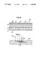
- FIG. 20is a cross-sectional view of an alternative embodiment of the present invention showing an alternative visual indicating mechanism
- FIG. 21is an alternative embodiment of the present invention showing an alternative means for passing light into a tracer fiber optic cable
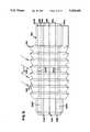
- FIGS. 22-27 and 27Aare alternative embodiments of a fiber optic cable containing secondary light transmission members
- FIG. 28is an alternative embodiment of a patch cord according to the present invention.
- FIG. 29is a cross-sectional view of an alterative embodiment of a coupling secured to a cable
- FIG. 30is a cross-sectional view of an alternative embodiment for focusing light into a secondary light transmission fiber through the surface of the fiber;
- FIG. 31is an alternative embodiment of the view of FIG. 30.
- FIG. 32is a prospective view of a self orientation block for securing the embodiment of FIG. 31 to a cable.
- the patch cord 10includes a cable 12 extending from a first end 12a to a second end 12a'.
- Connectors 14, 14'are connected to the cable 12 at ends 12a, 12a', respectively.
- the connectors 14, 14'may be any well-known fiber optic connectors such as so-called SC, FC, or D4 connectors or the like.
- the connectors 14, 14'would be well-known coaxial plugs.
- optical fiber cablesconsist of a centrally positioned optical fiber surrounded by strengthening material (such as Kevlar fibers) together with an outer sheathing.
- the fiberis commonly buffered.
- the cable 12 of the present inventionutilizes an additional fiber 22 as best shown with reference to FIGS. 2 and 3.
- Fiber 22need not be a telecommunications transmission quality fiber. Instead, any waveguide for carrying light is suitable.
- the cable 12includes a primary transmission member in the form of an optical fiber 14.
- a strengthening membersuch as Kevlar fibers 16 surround the fiber 14.
- a protective sheathing 18surrounds the Kevlar fibers 16.
- the sheathing 18includes a raised area 20 on a side of the cable 12 and extending the length of the cable 12.
- the sheathing 20surrounds a secondary transmission member 22 which, in a preferred embodiment, is an optical waveguide such as an optical fiber.
- FIG. 2shows an alternative embodiment of the cable 12.
- a cable 12"is shown having a centrally positioned primary transmission member in the form of an optical fiber 14".
- Kevlar fibers 16"surround fiber 14".
- the sheathing 18"includes a recessed area 20" which is provided with a secondary optical fiber 22" contained in area 20".
- FIGS. 2 and 3are merely illustrative of the various techniques by which a secondary optical fiber 22 may be carried on a fiber optic cable.
- the secondary fiber 22could simply be housed in a separate sheathing which is physically secured to the cable 12 through any suitable means such as tape, adhesive or the like. Additional alternative embodiments are shown in FIGS. 22-27 and 27A discussed later in this application.
- the secondary optical fiber 22terminates at first and second ends. Only first end 22a is shown in the drawings (for example FIG. 9). However, the first and second ends are identical and a description of one will suffice as a description of the other.
- first and second couplings 24, 24'Connected to the first and second ends of the secondary fiber 22 are first and second couplings 24, 24'.
- Each of the couplingsare identical and secured to the secondary fiber 22 in the cable 12 in an identical manner. Accordingly, a description of coupling 24 will suffice as a description of coupling 24'.
- the coupling 24is formed of clear injection molded plastic such as polycarbonate or acrylic.
- the coupling 24includes a generally cylindrical body 26.
- the body 26surrounds a coaxially disposed bore 28 extending through the length of the body 26 with the bore 28 having a diameter sized to pass the diameter of the main sheathing 18 of the cable 12 shown in FIG. 3.
- the body 26extends from a first end 30 to a second end 32.
- a secondary bore 34extends partially through the body 26 and is exposed through end 30.
- the bore 34terminates at a flat face 66 perpendicular to the axis of bore 34.
- Bore 34is positioned running parallel to bore 38 with bore 34 disposed on a side of bore 28 and in communication therewith as best shown in FIGS. 6 and 8. Bore 34 is sized to receive the secondary optical fiber 22.
- a locating flange 40surrounds body 26 between ends 30, 32.
- the flange 40has a flat radial surface 42 facing end 30 and flat radial surface 44 facing end 32.
- a plurality of annular ribs 46surround body 26 between end 30 and surface 42 with the ribs 46 having an outside diameter less than the outside diameter of the flange 40.
- annular ring 50Intricately formed on end 32 is an annular ring 50.
- the ring 50has a circumferential face 52 and a flat radial face 54 opposing surface 44.
- a beveled surface 56connects surfaces 54 and 52.
- end 32is flat with a beveled surface 58 connecting surfaces 32, 52.
- the ring 50is provided with a V-shaped cutout defined by a first arcuate reflective surface 60 and a second arcuate reflective surface 62 which meet at an apex 64 disposed in alignment with the axis of bore 34.
- bore 34terminates at a flat surface 66 which is parallel to and spaced from apex 64 by the material of ring 50.
- coupling 24is a solid piece of light transparent plastic.
- the lightpasses through the material of the ring 50 and hits apex 64 and arcuate surfaces 60, 62.
- the lightreflects off the arcuate surfaces 60, 62 and into the ring 50.
- the circumferential surface 52 as well as the beveled surfaces 56, 58all provide light reflecting or refracting surfaces such that the light is then directed throughout the ring and illuminates the ring 50.
- FIG. 9shows assembly of the coupling 24 onto the cable 12.
- the cable 12is stripped to expose a length of secondary fiber 22 sufficient to be received within bore 34.
- the coupling 24is passed on to cable 12 with sheathing 18 and fiber 14 extending through bore 28.
- the free end 22a of fiber 22is passed into bore 34 until the free end 22a opposes and abuts surface 66.
- the sizing of a gap between end 22a and surface 66is shown exaggerated as is the relative sizing between bore 34 and fiber 22).
- a shrink-wrap sleeve 70is passed over the cable 12 and is stopped against surface 42. Through applying heat, the sleeve 70 shrinks to be securely received on the cable 12 and securely received on the body 26.
- the ribs 46are provided giving secure attachment of the coupling 24 to the cable 12.
- illumination of the secondary transmission fiber 22causes light to pass axially from the fiber 22 through end 22a and pass through surface 66 resulting in illumination of ring 50.
- the structure thus describedillustrates the attachment of couplings 24, 24' to the cable 12 at opposite ends of the cable 12.
- the couplings 24, 24'are placed as close as possible to connectors 14, 14'.
- a power source clip 80is provided.
- clip 80is formed of the same light transparent plastic material as that of coupling 24.
- the clip 80includes a cylindrical body 82 having a bore 84 sized to receive the body 26 of coupling 24.
- An axial slot 86extends through the body 82 in communication with bore 84.
- lever arms 88 and 90are provided on a side of the body 82 opposite slot 86.
- Each of arms 88includes ribs 92 to permit a technician to securely grasp the levers 88, 90 and force the levers 88, 90 toward one another resulting in enlargement of the bore 84.
- the slot 86opens to permit placement of the clip 80 on either coupling 24 or 24'.
- the ribs 88, 90are joined at a fulcrum point 94.
- the body 82also includes a plurality of secondary bores 96 extending partially through the body from a first end 98 toward a second end 101.
- the bores 96are sized to receive source optical fibers (only one of which is shown as fiber 110 in FIG. 19).
- the bore 84is provided with an interior ring 102 extending between first and second flat annular surfaces 104, 106.
- the ring 102is sized to be received between surfaces 44 and 54 of coupling 24.
- the end 101 of the bodyis provided with a 45° chamfer 100 (measured with respect to the axis X--X).
- the purpose of the chamfer 100will become apparent with reference to FIG. 15. Namely, fiber 110 is placed within bore 96 with the end 112 of the fiber 110 opposing surface 113. Since the chamfer 100 is at a 45° angle to surface 113, light exiting from end 112 passes through surface 113 and reflects off the chamfer 100 radially toward the axis X--X.
- the ring 102separates bore 84 to define groove 115 sized to receive ring 50 with surface 52 opposing chamfer 100.
- a groove 117is formed on an opposite side of ring 102. Groove 117 is sized to receive flange 40.
- FIGS. 17 and 18show the clip 80 attached to a coupling 24.
- the lightis reflected radially inwardly by the chamfer 100 and into the ring 50.
- fiber 110is not shown in FIGS. 17 or 18 but is shown in FIG. 19.
- the chamfer 100radially opposes the ring 50. Accordingly, when light enters into the ring 50, the light reflects off of the surfaces 60, 62 of the ring and projects into a fiber end 22a connected to the coupling 24.
- a patch cord 10In use, four fibers 110 are received within bores 96. The fibers 110 are all connected to a common light source 120. As a result, in use, a patch cord 10 according to the present invention extends between two pieces of fiber optic equipment.
- a technicianplaces the clip 80 on one of the connection, a technician places the clip 80 on one of the couplings 24.
- fibers 110are illuminated resulting in light passing from the fibers 110 and through light transmission surface 112 and into the clip 80.
- the light within the clip 80is directed by the chamfer 110 into ring 50.
- Light within ring 50is directed by the reflective surfaces of the ring 50 into the fiber end 22a of secondary fiber 22.
- the lightpasses through fiber 22 to the second coupling 24' with the light of the fiber illuminating the ring of the secondary coupling 24'. Accordingly, the technician can visually identify the second end of the patch cord.
- Second annular groove 115receives the ring 50. Accordingly, upon placement of the clip 80 the coupling 24 is accurately aligned with the clip 80 such that the chamfer surface 100 is opposing the ring 50 to ensure an optical coupling between the ring and the chamfer 100. The reader will also note that the clip 80 can be placed onto the coupling 24 in any position around the radius of the coupling.
- electrically conductive contactscould be exposed connected to the electrical wires such that a clip having an exposed contact could be connected to the coupling with the exposed contacts of the clip connected to the exposed contacts on the coupling.
- a battery or other electrical power sourcecould be connected to the coupling to energize the secondary transmission members and illuminate the LED's carried on the couplings.
- FIG. 20Another option is shown in FIG. 20.
- the cable 12'"is shown including a primary transmission element in the form of an optical fiber 15'" surrounded by a Kevlar fiber 16'".
- the sheathing 18'"surrounds the Kevlar 16'".
- the sheathing 18'"includes an enlarged portion 20'" which contains a secondary transmission element in the form of an optical fiber 22'".
- the enlargement 20'"could be eliminated and a bare fiber 22'" could simply be secured to the outer sheathing 18'" through any suitable means.
- a plurality of V-shaped notches 21'"are formed along the length of the cable 12'" piercing the sheathing 20'" and notching the secondary fiber 22'".
- the notches 21'"are attenuation points. Accordingly, when light has passed through secondary fiber 22'", the light reflects off of the surfaces of the notches 21'" to cause a visually perceptible glow at the location of the notches.
- the notchescould be provided at the end of the cable adjacent the cable connectors. Also, the notches 21'" can be provided along the entire length of the cable such that the entire cable will have glowing points to permit a technician to easily trace the cable.
- FIG. 21shows an alternative embodiment for projecting light into a fiber 22"".
- a plurality of sawtoothed notches 21""are shown.
- the notchesinclude a surface 23"" which projects generally radially to the axis of the fiber 22"".
- the notches 21""also include a surface 25"" which projects upwardly from surface 23"" at an acute angle. Accordingly, light rays 27"" directed generally radially towards fiber 22"" reflect off of surface 25"" and pass through surface 23"". Accordingly, light is injected into the fiber 22"” simply by projecting the light radially towards the fiber 22"" in the vicinity of the notches 21"".
- the cable of the patch cordneed have only a means at one end for receiving energy, an energy transmission member and a means at a second end for providing a visual indicator activated upon energy being transmitted.
- FIGS. 22-27 and 27Ashow a variety of alternative embodiments for securing secondary light transmission means to an optical fiber.
- a cross-section of an optical fiber patch cord cableis shown.
- the cable 212aincludes a centrally positioned optical fiber 215a surrounded by a buffer 217a, as is conventional.
- the buffered fiberSurrounding the buffered fiber are strength members such as Kevlar 216a, as is conventional.
- An outer PVC jacket 218asurrounds the strengthening member 216a.
- two light transmission waveguides or fibers 222a, 222a'are embedded within the cable jacket 218a.
- the waveguides 222a, 222a'are the secondary transmission waveguides which carry the illumination for the tracer function similar to the function of fiber 22 of FIG. 3.
- FIGS. 23-27 and 27Aelements similar to those of FIG. 22 are similarly numbered. However, the distinguishing letter “a” to the element numbers of FIG. 22 are substituted for "b", “c", “d”, “e”, “f” and “g” in FIGS. 23, 24, 25, 26, 27, and 27A, respectively, to distinguish the embodiments.
- the construction of the cable 212bis the same as that of 212a with the exception that the secondary transmission fibers 222b, 222b' are only partially embedded within the outer jacket 218b such that the surfaces of the secondary transmission fibers 222b, 222b' are exposed along the length of the cable.
- the secondary light transmission fibers 222c, 222c'are contained within enlarged areas, 220c, 220c' of the outer jacket 218c.
- the outer jacketcontains an inner section 218d surrounded by an outer section 218d'. Sandwiched between sections 218d and 218d' is a cylindrical light transmission layer 222d which is formed of clear flexible plastic such that light can be carried and transmitted through layer 222d.
- the embodiment of FIG. 26includes a plurality of secondary light
- FIG. 27includes a cylindrical clear plastic outer light transmission jacket 222f which surrounds the cable jacket 218f.
- the light transmission jacket 222fhas its outer cylindrical surface completely exposed along the length of the cable.
- the buffered optical fiber 215gis centrally positioned within the strength members 216g.
- the PVC sheathing 218gsurrounds the strength members.
- Diametrically opposed optical waveguides 222g, 222g'are directly extruded onto the jacket 218g. So extruded, the waveguides 222g, 222g' are positioned on an outer surface of the jacket such that an outer surface of the waveguides 222g, 222g' are exposed along an entire length of the jacket 218g.
- FIGS. 28-33show alternative embodiments for injecting light into the secondary light transmission members.
- a patch cord 310is shown including a cable such as cable 212b of FIG. 23.
- the cable 212bterminates at fiber optic connectors 314, 314'.
- Couplings 324, 324'are positioned on the cable 312 adjacent connectors 314, 314'.
- the cable 212bis shown in cross-sectional view with coupling 324.
- the coupling 324includes a collar portion 325 which surrounds the cable 212b.
- a light transmission surface 326is provided to be parallel to and abutting the terminal ends of secondary fibers 212b, 212b'.
- the coupling 324further includes a light directing surface 327 disposed at about 45° to the surface 326 to receive light rays 328 passing axially through fibers 212b, 212b' with the surface 327 angled to direct the light rays 328 radially outwardly as shown in FIG. 29.
- Radially opposing surfaces 327, a convex annular surface 329is provided to focus the light 328 directed off of surface 327.
- FIG. 29the light is injected into the ends of the fibers 212b, 212b'.
- lightcan be coupled through the surface of the secondary light transmission fibers.
- FIGS. 30-33show a coupling for projecting light into the secondary light transmission members through the surface of the secondary light transmission members.
- a cablesuch as cable 212b is utilized.
- FIG. 30for purposes of clarity, the entire cable 212b is not shown. Instead, only secondary light transmission fibers 222b and 222b' are shown. The surfaces of fibers 222b, 222b' are provided with the notched surfaces 223, 223' of construction such as that shown in FIG. 21.
- a coupling 424is provided having an inner bore 425 surrounding fibers 222b, 222b'.
- the coupling 424is clear plastic and on its radially outer surface includes a plurality of convex rings 426.
- lightis projected at the coupling 424 with the light rays 428 extending at an angle to the radius of the coupling 424.
- the lightis focused by the rings 426 to the microprism of the notches 223, 223' and injected into the fibers 222b, 222b'.
- FIG. 31an alternative embodiment is shown utilizing a fiber having the construction of FIG. 23.
- a coupling 524similar to coupling 424 of FIG. 30, is provided.
- Coupling 524does not included convex rings. Instead, the rings 526 of coupling 524 are generally triangular in cross section to provide a more enhanced prismatic effect for projecting light rays 528 toward the microprism of notches 223b, 223b' of fiber 222b, 222b'.
- FIG. 32shows a self orientation block 550 cylindrically formed with coupling 524.
- the block 550includes a bore 552 extending therethrough sized to receive a cable.
- Block 550is shown for use with the embodiment of FIG. 23 and includes diametrically opposed secondary bores 553 sized to receive and retain fibers 222b, 222b'. Accordingly, with the cable 212b passed through block 550, the cable and the block do not rotate relative to one another.
- a clip having the function of clip 80 of FIG. 19it is preferred that such a clip will be provided with a cylindrical lens 600 having its longitudinal axis generally perpendicular to the rings 526. The cylindrical lens will focus light from a source into the rings 526.
Landscapes
- Physics & Mathematics (AREA)
- General Physics & Mathematics (AREA)
- Optics & Photonics (AREA)
- Optical Couplings Of Light Guides (AREA)
- Glass Compositions (AREA)
- Light Guides In General And Applications Therefor (AREA)
- Devices Affording Protection Of Roads Or Walls For Sound Insulation (AREA)
- Insulated Conductors (AREA)
- Communication Cables (AREA)
- Tents Or Canopies (AREA)
- Materials For Medical Uses (AREA)
Abstract
Description
Claims (29)
Priority Applications (10)
| Application Number | Priority Date | Filing Date | Title |
|---|---|---|---|
| US08/017,156US5305405A (en) | 1993-02-25 | 1993-02-25 | Patch cord |
| TW082101711ATW209892B (en) | 1993-02-25 | 1993-03-09 | |
| EP94906556AEP0686267B1 (en) | 1993-02-25 | 1994-01-07 | Patch cord |
| CA002155211ACA2155211C (en) | 1993-02-25 | 1994-01-07 | Patch cord |
| NZ261472ANZ261472A (en) | 1993-02-25 | 1994-01-07 | Patch cord with visible indicator for tracing signal |
| DE69402837TDE69402837T2 (en) | 1993-02-25 | 1994-01-07 | MANUFACTURING LINE |
| AU60234/94AAU675697B2 (en) | 1993-02-25 | 1994-01-07 | Patch cord |
| AT94906556TATE152246T1 (en) | 1993-02-25 | 1994-01-07 | SAGGING MANAGEMENT |
| PCT/US1994/000252WO1994019702A1 (en) | 1993-02-25 | 1994-01-07 | Patch cord |
| MX9401337AMX9401337A (en) | 1993-02-25 | 1994-02-22 | COMMUTATION CORD FOR THE TELECOMMUNICATION INDUSTRY. |
Applications Claiming Priority (1)
| Application Number | Priority Date | Filing Date | Title |
|---|---|---|---|
| US08/017,156US5305405A (en) | 1993-02-25 | 1993-02-25 | Patch cord |
Publications (1)
| Publication Number | Publication Date |
|---|---|
| US5305405Atrue US5305405A (en) | 1994-04-19 |
Family
ID=21781036
Family Applications (1)
| Application Number | Title | Priority Date | Filing Date |
|---|---|---|---|
| US08/017,156Expired - LifetimeUS5305405A (en) | 1993-02-25 | 1993-02-25 | Patch cord |
Country Status (10)
| Country | Link |
|---|---|
| US (1) | US5305405A (en) |
| EP (1) | EP0686267B1 (en) |
| AT (1) | ATE152246T1 (en) |
| AU (1) | AU675697B2 (en) |
| CA (1) | CA2155211C (en) |
| DE (1) | DE69402837T2 (en) |
| MX (1) | MX9401337A (en) |
| NZ (1) | NZ261472A (en) |
| TW (1) | TW209892B (en) |
| WO (1) | WO1994019702A1 (en) |
Cited By (104)
| Publication number | Priority date | Publication date | Assignee | Title |
|---|---|---|---|---|
| US5394503A (en)* | 1993-10-08 | 1995-02-28 | Data Switch Corporation | Optical fiber connection monitoring apparatus, patch panel control system and method of using same |
| US5463706A (en)* | 1994-02-16 | 1995-10-31 | Thomas & Betts Corporation | Light traceable transmission conduit assembly |
| EP0687115A2 (en) | 1994-06-09 | 1995-12-13 | AT&T Corp. | Telecommunications distribution frame with tracing |
| US5666453A (en)* | 1994-07-15 | 1997-09-09 | Roy Witte | Fiber optic jumper cables and tracing method using same |
| US5764348A (en)* | 1996-10-01 | 1998-06-09 | Bloom; Cary | Optical switching assembly for testing fiber optic devices |
| US5764043A (en)* | 1996-12-20 | 1998-06-09 | Siecor Corporation | Traceable patch cord and connector assembly and method for locating patch cord ends |
| US5805757A (en)* | 1996-12-10 | 1998-09-08 | Bloom; Cary | Apparatus and method for preserving optical characteristics of a fiber optic device |
| US5815619A (en)* | 1996-12-10 | 1998-09-29 | Bloom; Cary | Fiber optic connector hermetically terminated |
| US5871559A (en)* | 1996-12-10 | 1999-02-16 | Bloom; Cary | Arrangement for automated fabrication of fiber optic devices |
| US5917975A (en)* | 1996-12-10 | 1999-06-29 | Bloom; Cary | Apparatus for, and method of, forming a low stress tight fit of an optical fiber to an external element |
| US5931983A (en)* | 1996-09-24 | 1999-08-03 | Bloom; Cary | Method of forming a fiber optic coupler by dynamically adjusting pulling speed |
| US5971629A (en)* | 1996-07-12 | 1999-10-26 | Bloom; Cary | Apparatus and method bonding optical fiber and/or device to external element using compliant material interface |
| US6000858A (en)* | 1996-07-12 | 1999-12-14 | Bloom; Cary | Apparatus for, and method of, forming a low stress tight fit of an optical fiber to an external element |
| US6002331A (en)* | 1998-07-20 | 1999-12-14 | Laor; Herzel | Method and apparatus for identifying and tracking connections of communication lines |
| US6003341A (en)* | 1996-12-10 | 1999-12-21 | Bloom; Cary | Device for making fiber couplers automatically |
| US6074101A (en)* | 1996-12-10 | 2000-06-13 | Bloom; Cary | Apparatus for, and method of, forming a low stress tight fit of an optical fiber to an external element |
| US6151357A (en)* | 1998-01-16 | 2000-11-21 | Aspect Communications Corporation | Method and apparatus for displaying a visual indication of a transmission status |
| US6177985B1 (en) | 1996-10-01 | 2001-01-23 | Cary Bloom | Apparatus and method for testing optical fiber system components |
| US6285293B1 (en)* | 1999-02-10 | 2001-09-04 | Avaya Technology Corp. | System and method for addressing and tracing patch cords in a dedicated telecommunications system |
| DE10041438A1 (en)* | 2000-08-23 | 2002-03-14 | Rxs Kabelgarnituren Gmbh & Co | Arrangement for coupling a plurality of first optical waveguide fibers to a plurality of second optical waveguide fibers |
| US6370294B1 (en) | 1999-06-25 | 2002-04-09 | Adc Telecommunications, Inc. | Fiber optic circuit and module with switch |
| US20030152344A1 (en)* | 2000-03-06 | 2003-08-14 | Patrice Brunet | Device for visual identification of cables or conduits |
| US20040033716A1 (en)* | 2002-08-14 | 2004-02-19 | Bruce Musolf | Cross-connect jumper assembly having tracer lamp |
| US20040204916A1 (en)* | 2000-03-14 | 2004-10-14 | David Solomon I. | System for monitoring connection pattern of data ports |
| US20040219827A1 (en)* | 1999-04-06 | 2004-11-04 | David Solomon I. | System for monitoring connection pattern of data ports |
| US20050052174A1 (en)* | 2003-09-05 | 2005-03-10 | Angelo Deborah A. | Traceable patch cable and connector assembly and method for identifying patch cable ends |
| US20060094291A1 (en)* | 2004-11-03 | 2006-05-04 | Caveney Jack E | Method and apparatus for patch panel patch cord documentation and revision |
| US20060262727A1 (en)* | 2005-05-19 | 2006-11-23 | Panduit Corp. | Method and apparatus for documenting network paths |
| US20060282529A1 (en)* | 2005-06-14 | 2006-12-14 | Panduit Corp. | Method and apparatus for monitoring physical network topology information |
| US20070032124A1 (en)* | 2005-08-08 | 2007-02-08 | Panduit Corp. | Systems and methods for detecting a patch cord end connection |
| US20070117444A1 (en)* | 2005-11-18 | 2007-05-24 | Panduit Corp. | Smart cable provisioning for a patch cord management system |
| US20070132503A1 (en)* | 2005-12-06 | 2007-06-14 | Panduit Corp. | Power patch panel with guided mac capability |
| US20070207666A1 (en)* | 2006-02-14 | 2007-09-06 | Panduit Corp. | Method and Apparatus for Patch Panel Patch Cord Documentation and Revision |
| US20070230452A1 (en)* | 2006-03-22 | 2007-10-04 | Steve Hough | Intelligent patching system and method |
| US20070243725A1 (en)* | 2005-08-26 | 2007-10-18 | Panduit Corp. | Patch Field Documentation and Revision Systems |
| US20080049627A1 (en)* | 2005-06-14 | 2008-02-28 | Panduit Corp. | Method and Apparatus for Monitoring Physical Network Topology Information |
| US20080100467A1 (en)* | 2006-10-31 | 2008-05-01 | Downie John D | Radio frequency identification of component connections |
| US20080113560A1 (en)* | 2003-08-06 | 2008-05-15 | Panduit Corp. | Network Managed Device Installation and Provisioning Technique |
| FR2909186A1 (en)* | 2006-11-24 | 2008-05-30 | Patrice Brunet | DEVICE FOR VISUAL REPERAGE OF CABLES OR CONDUITS OF ALL THEIR LENGTH. |
| US20080175159A1 (en)* | 2006-12-13 | 2008-07-24 | Panduit Corp. | High Performance Three-Port Switch for Managed Ethernet Systems |
| US7519000B2 (en) | 2002-01-30 | 2009-04-14 | Panduit Corp. | Systems and methods for managing a network |
| US20090097846A1 (en)* | 2006-12-14 | 2009-04-16 | David Robert Kozischek | RFID Systems and Methods for Optical Fiber Network Deployment and Maintenance |
| US20090215310A1 (en)* | 2006-10-10 | 2009-08-27 | Adc Gmbh | Upgradeable telecommunications patch panel and method of upgrading same |
| US7656903B2 (en) | 2002-01-30 | 2010-02-02 | Panduit Corp. | System and methods for documenting networks with electronic modules |
| US20100052863A1 (en)* | 2008-08-28 | 2010-03-04 | Renfro Jr James G | RFID-based systems and methods for collecting telecommunications network information |
| US20100157516A1 (en)* | 2008-12-22 | 2010-06-24 | Panduit Corp. | Physical infrastructure management system |
| US20100178058A1 (en)* | 2006-12-14 | 2010-07-15 | Kozischek David R | Rfid systems and methods for optical fiber network deployment and maintenance |
| US20100184323A1 (en)* | 2008-11-12 | 2010-07-22 | Panduit Corp. | Patch Cord with Insertion Detection and Light Illumination Capabilities |
| US7772975B2 (en) | 2006-10-31 | 2010-08-10 | Corning Cable Systems, Llc | System for mapping connections using RFID function |
| US20100210134A1 (en)* | 2009-02-19 | 2010-08-19 | Panduit Corp. | Cross connect patch guidance system |
| US20100267274A1 (en)* | 2007-10-19 | 2010-10-21 | Panduit Corp | Communication port identification system |
| US20110034068A1 (en)* | 2009-08-05 | 2011-02-10 | Realm Communications Group, Inc. | Networking cable with tracer optical waveguide |
| US7938700B2 (en) | 2008-02-21 | 2011-05-10 | Panduit Corp. | Intelligent inter-connect and cross-connect patching system |
| US20110116748A1 (en)* | 2009-10-16 | 2011-05-19 | Adc Telecommunications, Inc. | Managed connectivity in fiber optic systems and methods thereof |
| US7965186B2 (en) | 2007-03-09 | 2011-06-21 | Corning Cable Systems, Llc | Passive RFID elements having visual indicators |
| US7978845B2 (en) | 2005-09-28 | 2011-07-12 | Panduit Corp. | Powered patch panel |
| US20110228473A1 (en)* | 2010-02-12 | 2011-09-22 | Chad Anderson | Communications bladed panel systems |
| US20110235979A1 (en)* | 2010-02-12 | 2011-09-29 | John Anderson | Managed fiber connectivity systems |
| US8248208B2 (en) | 2008-07-15 | 2012-08-21 | Corning Cable Systems, Llc. | RFID-based active labeling system for telecommunication systems |
| US8565572B2 (en) | 2010-06-23 | 2013-10-22 | Adc Telecommunications, Inc. | Telecommunications assembly |
| US8696369B2 (en) | 2010-09-09 | 2014-04-15 | Adc Telecommunications, Inc. | Electrical plug with main contacts and retractable secondary contacts |
| US8715012B2 (en) | 2011-04-15 | 2014-05-06 | Adc Telecommunications, Inc. | Managed electrical connectivity systems |
| US8757895B2 (en) | 2011-04-15 | 2014-06-24 | Adc Telecommunications, Inc. | Managed fiber connectivity systems |
| US8897637B2 (en) | 2009-04-22 | 2014-11-25 | Adc Gmbh | Method and arrangement for identifying at least one object |
| WO2015023459A1 (en)* | 2013-08-12 | 2015-02-19 | Corning Optical Communications LLC | Optical fiber cable assembly comprising optical tracer fiber |
| US8992260B2 (en) | 2009-10-16 | 2015-03-31 | Adc Telecommunications, Inc. | Managed connectivity in electrical systems and methods thereof |
| US8992261B2 (en) | 2010-10-22 | 2015-03-31 | Adc Telecommunications, Inc. | Single-piece plug nose with multiple contact sets |
| US9054440B2 (en) | 2009-10-19 | 2015-06-09 | Adc Telecommunications, Inc. | Managed electrical connectivity systems |
| US9064022B2 (en) | 2011-05-17 | 2015-06-23 | Adc Telecommunications, Inc. | Component identification and tracking system for telecommunication networks |
| US20150205056A1 (en)* | 2014-01-20 | 2015-07-23 | Jyh Eng Technology Co., Ltd. | Tracking jumper cable assembly |
| US9093796B2 (en) | 2012-07-06 | 2015-07-28 | Adc Telecommunications, Inc. | Managed electrical connectivity systems |
| US9203198B2 (en) | 2012-09-28 | 2015-12-01 | Commscope Technologies Llc | Low profile faceplate having managed connectivity |
| US9219543B2 (en) | 2012-07-11 | 2015-12-22 | Commscope Technologies Llc | Monitoring optical decay in fiber connectivity systems |
| US9285552B2 (en) | 2013-02-05 | 2016-03-15 | Commscope Technologies Llc | Optical assemblies with managed connectivity |
| US9304278B1 (en) | 2015-03-31 | 2016-04-05 | Corning Optical Communications LLC | Traceable cable with side-emitting optical fiber and method of forming the same |
| US9379501B2 (en) | 2013-02-05 | 2016-06-28 | Commscope Technologies Llc | Optical assemblies with managed connectivity |
| US9423570B2 (en) | 2013-02-05 | 2016-08-23 | Commscope Technologies Llc | Optical assemblies with managed connectivity |
| US9453971B2 (en) | 2012-07-11 | 2016-09-27 | Commscope Technologies Llc | Managed fiber connectivity systems |
| US9470742B2 (en) | 2012-08-03 | 2016-10-18 | Commscope Technologies Llc | Managed fiber connectivity systems |
| US9500814B2 (en) | 2014-03-26 | 2016-11-22 | Commscope Technologies Llc | Optical adapter module with managed connectivity |
| US9563832B2 (en) | 2012-10-08 | 2017-02-07 | Corning Incorporated | Excess radio-frequency (RF) power storage and power sharing RF identification (RFID) tags, and related connection systems and methods |
| US9671551B2 (en) | 2012-02-13 | 2017-06-06 | Corning Optical Communications LLC | Visual tracer system for fiber optic cable |
| US9742633B2 (en) | 1997-11-17 | 2017-08-22 | Commscope Technologies Llc | System and method for electronically identifying connections of a system used to make connections |
| US9798096B2 (en) | 2014-02-07 | 2017-10-24 | Commscope Technologies Llc | Managed fiber connectivity systems |
| US20170315302A1 (en)* | 2014-10-20 | 2017-11-02 | Zte Corporation | Quartz plastic composite optical fiber assembly, recognition method and device |
| WO2018151824A1 (en)* | 2017-02-16 | 2018-08-23 | Go!Foton Holdings, Inc. | Optical cable with illumination path |
| US10101553B2 (en) | 2015-05-20 | 2018-10-16 | Corning Optical Communications LLC | Traceable cable with side-emitting optical fiber and method of forming the same |
| US10101545B2 (en) | 2015-10-30 | 2018-10-16 | Corning Optical Communications LLC | Traceable cable assembly and connector |
| US10107983B2 (en) | 2016-04-29 | 2018-10-23 | Corning Optical Communications LLC | Preferential mode coupling for enhanced traceable patch cord performance |
| US10153954B2 (en) | 2013-08-14 | 2018-12-11 | Commscope Technologies Llc | Inferring physical layer connection status of generic cables from planned single-end connection events |
| US10185111B2 (en) | 2016-04-08 | 2019-01-22 | Corning Optical Communications LLC | Traceable end point cable assembly |
| US10222560B2 (en) | 2016-12-21 | 2019-03-05 | Corning Research & Development Corporation | Traceable fiber optic cable assembly with fiber guide and tracing optical fibers for carrying light received from a light launch device |
| US10228526B2 (en) | 2015-03-31 | 2019-03-12 | Corning Optical Communications LLC | Traceable cable with side-emitting optical fiber and method of forming the same |
| US10234614B2 (en) | 2017-01-20 | 2019-03-19 | Corning Research & Development Corporation | Light source assemblies and systems and methods with mode homogenization |
| US10234648B2 (en) | 2007-08-06 | 2019-03-19 | Commscope Technologies Llc | Fiber optic enclosure with internal cable spool |
| US10338317B2 (en) | 2015-07-17 | 2019-07-02 | Corning Optical Communications LLC | Systems and methods for traceable cables |
| US10371914B2 (en) | 2011-06-24 | 2019-08-06 | Commscope Technologies Llc | Fiber termination enclosure with modular plate assemblies |
| US10379309B2 (en) | 2014-11-18 | 2019-08-13 | Corning Optical Communications LLC | Traceable optical fiber cable and filtered viewing device for enhanced traceability |
| US10534135B2 (en) | 2015-07-17 | 2020-01-14 | Corning Optical Communications LLC | Systems and methods for tracing cables and cables for such systems and methods |
| US10539747B2 (en) | 2017-12-05 | 2020-01-21 | Corning Research & Development Corporation | Bend induced light scattering fiber and cable assemblies and method of making |
| US10539758B2 (en) | 2017-12-05 | 2020-01-21 | Corning Research & Development Corporation | Traceable fiber optic cable assembly with indication of polarity |
| US10545305B2 (en) | 2012-12-19 | 2020-01-28 | CommScope Connectivity Belgium BVBA | Distribution device with incrementally added splitters |
| US10627592B2 (en) | 2007-05-07 | 2020-04-21 | Commscope Technologies Llc | Fiber optic assembly with cable spool |
| US11726281B2 (en) | 2018-11-16 | 2023-08-15 | Commscope Technologies Llc | Fiber optic cable assembly with a tracer component |
Families Citing this family (2)
| Publication number | Priority date | Publication date | Assignee | Title |
|---|---|---|---|---|
| DE10239602B3 (en)* | 2002-08-28 | 2004-02-19 | Krone Gmbh | Optical signal system, for a railway shunting yard, has a green-emitting laser coupled to an optic fiber along at least part of the length of connecting cable, giving externally visible illumination |
| FR3012249A1 (en) | 2013-10-22 | 2015-04-24 | Bull Sas | CABLE NETWORK COMPRISING A VISUAL REFERENCE DEVICE AND VISUAL TERMINAL SCREENING DEVICE FOR NETWORK CABLE. |
Citations (5)
| Publication number | Priority date | Publication date | Assignee | Title |
|---|---|---|---|---|
| US4653848A (en)* | 1983-06-23 | 1987-03-31 | Jacobus Kloots | Fiberoptic cables with angled connectors |
| US4707073A (en)* | 1985-09-04 | 1987-11-17 | Raytheon Company | Fiber optic beam delivery system for high-power laser |
| US4887190A (en)* | 1988-10-15 | 1989-12-12 | In Focis Devices Inc. | High intensity fiber optic lighting system |
| US4978194A (en)* | 1989-08-28 | 1990-12-18 | Raynet Corporation | Stepped cable block |
| US5228109A (en)* | 1990-08-24 | 1993-07-13 | Matsushita Electric Industrial Co., Ltd. | Light beam heating apparatus and method utilizing a fiber optic cable with random fiber array |
Family Cites Families (2)
| Publication number | Priority date | Publication date | Assignee | Title |
|---|---|---|---|---|
| GB2236398A (en)* | 1989-09-29 | 1991-04-03 | James Alexander Carter | Self documenting patch panel |
| FR2680067B1 (en)* | 1991-08-01 | 1995-05-12 | Cit Alcatel | METHOD FOR CONTROLLING A LINE DISTRIBUTOR; AUXILIARY CABLE, CONNECTOR AND DISTRIBUTOR FOR THE IMPLEMENTATION OF THIS PROCESS. |
- 1993
- 1993-02-25USUS08/017,156patent/US5305405A/ennot_activeExpired - Lifetime
- 1993-03-09TWTW082101711Apatent/TW209892B/zhactive
- 1994
- 1994-01-07WOPCT/US1994/000252patent/WO1994019702A1/enactiveIP Right Grant
- 1994-01-07AUAU60234/94Apatent/AU675697B2/ennot_activeExpired
- 1994-01-07EPEP94906556Apatent/EP0686267B1/ennot_activeExpired - Lifetime
- 1994-01-07ATAT94906556Tpatent/ATE152246T1/ennot_activeIP Right Cessation
- 1994-01-07DEDE69402837Tpatent/DE69402837T2/ennot_activeExpired - Lifetime
- 1994-01-07CACA002155211Apatent/CA2155211C/ennot_activeExpired - Lifetime
- 1994-01-07NZNZ261472Apatent/NZ261472A/ennot_activeIP Right Cessation
- 1994-02-22MXMX9401337Apatent/MX9401337A/enunknown
Patent Citations (5)
| Publication number | Priority date | Publication date | Assignee | Title |
|---|---|---|---|---|
| US4653848A (en)* | 1983-06-23 | 1987-03-31 | Jacobus Kloots | Fiberoptic cables with angled connectors |
| US4707073A (en)* | 1985-09-04 | 1987-11-17 | Raytheon Company | Fiber optic beam delivery system for high-power laser |
| US4887190A (en)* | 1988-10-15 | 1989-12-12 | In Focis Devices Inc. | High intensity fiber optic lighting system |
| US4978194A (en)* | 1989-08-28 | 1990-12-18 | Raynet Corporation | Stepped cable block |
| US5228109A (en)* | 1990-08-24 | 1993-07-13 | Matsushita Electric Industrial Co., Ltd. | Light beam heating apparatus and method utilizing a fiber optic cable with random fiber array |
Cited By (267)
| Publication number | Priority date | Publication date | Assignee | Title |
|---|---|---|---|---|
| US5394503A (en)* | 1993-10-08 | 1995-02-28 | Data Switch Corporation | Optical fiber connection monitoring apparatus, patch panel control system and method of using same |
| WO1995022069A1 (en)* | 1994-02-15 | 1995-08-17 | Data Switch Corporation | Optical fiber connection monitoring apparatus, patch panel control system and method of using same |
| US5463706A (en)* | 1994-02-16 | 1995-10-31 | Thomas & Betts Corporation | Light traceable transmission conduit assembly |
| EP0687115A3 (en)* | 1994-06-09 | 1998-09-02 | AT&T Corp. | Telecommunications distribution frame with tracing |
| EP0687115A2 (en) | 1994-06-09 | 1995-12-13 | AT&T Corp. | Telecommunications distribution frame with tracing |
| US5666453A (en)* | 1994-07-15 | 1997-09-09 | Roy Witte | Fiber optic jumper cables and tracing method using same |
| US6244756B1 (en) | 1996-07-12 | 2001-06-12 | Cary Bloom | Apparatus and method bonding optical fiber and/or device to external element using compliant material interface |
| US6000858A (en)* | 1996-07-12 | 1999-12-14 | Bloom; Cary | Apparatus for, and method of, forming a low stress tight fit of an optical fiber to an external element |
| US5971629A (en)* | 1996-07-12 | 1999-10-26 | Bloom; Cary | Apparatus and method bonding optical fiber and/or device to external element using compliant material interface |
| US5948134A (en)* | 1996-09-24 | 1999-09-07 | Bloom; Cary | Apparatus for forming a fiber optic coupler by dynamically adjusting pulling speed and heat intensity |
| US6112555A (en)* | 1996-09-24 | 2000-09-05 | Bloom; Cary | Method for changing incident heat and pulling of an optic fiber via monitoring of rate of change of coupling ratio |
| US6018965A (en)* | 1996-09-24 | 2000-02-01 | Bloom; Cary | Method of forming a fiber optic coupler by dynamically adjusting pulling speed and heat intensity based on a monitored rate of change in the coupling ratio |
| US5931983A (en)* | 1996-09-24 | 1999-08-03 | Bloom; Cary | Method of forming a fiber optic coupler by dynamically adjusting pulling speed |
| US6177985B1 (en) | 1996-10-01 | 2001-01-23 | Cary Bloom | Apparatus and method for testing optical fiber system components |
| US6108074A (en)* | 1996-10-01 | 2000-08-22 | Bloom; Cary | Optical switching assembly for testing fiber optic device |
| US5764348A (en)* | 1996-10-01 | 1998-06-09 | Bloom; Cary | Optical switching assembly for testing fiber optic devices |
| US5815619A (en)* | 1996-12-10 | 1998-09-29 | Bloom; Cary | Fiber optic connector hermetically terminated |
| US5871559A (en)* | 1996-12-10 | 1999-02-16 | Bloom; Cary | Arrangement for automated fabrication of fiber optic devices |
| US6003341A (en)* | 1996-12-10 | 1999-12-21 | Bloom; Cary | Device for making fiber couplers automatically |
| US6074101A (en)* | 1996-12-10 | 2000-06-13 | Bloom; Cary | Apparatus for, and method of, forming a low stress tight fit of an optical fiber to an external element |
| US5999684A (en)* | 1996-12-10 | 1999-12-07 | Bloom; Cary | Apparatus and method for preserving optical characteristics of a fiber optic device |
| US5805757A (en)* | 1996-12-10 | 1998-09-08 | Bloom; Cary | Apparatus and method for preserving optical characteristics of a fiber optic device |
| US5917975A (en)* | 1996-12-10 | 1999-06-29 | Bloom; Cary | Apparatus for, and method of, forming a low stress tight fit of an optical fiber to an external element |
| US5970749A (en)* | 1996-12-10 | 1999-10-26 | Bloom; Cary | Arrangement for automated fabrication of fiber optic devices |
| US6237370B1 (en) | 1996-12-10 | 2001-05-29 | Cary Bloom | Apparatus for automated production, and/or packaging and/or testing of fiber optic devices including optical fiber system components and optical fibers |
| US5764043A (en)* | 1996-12-20 | 1998-06-09 | Siecor Corporation | Traceable patch cord and connector assembly and method for locating patch cord ends |
| US9742633B2 (en) | 1997-11-17 | 2017-08-22 | Commscope Technologies Llc | System and method for electronically identifying connections of a system used to make connections |
| US6151357A (en)* | 1998-01-16 | 2000-11-21 | Aspect Communications Corporation | Method and apparatus for displaying a visual indication of a transmission status |
| US6002331A (en)* | 1998-07-20 | 1999-12-14 | Laor; Herzel | Method and apparatus for identifying and tracking connections of communication lines |
| US6285293B1 (en)* | 1999-02-10 | 2001-09-04 | Avaya Technology Corp. | System and method for addressing and tracing patch cords in a dedicated telecommunications system |
| US7160143B2 (en) | 1999-04-06 | 2007-01-09 | Itracs Corporation | System for monitoring connection pattern of data ports |
| US20040219827A1 (en)* | 1999-04-06 | 2004-11-04 | David Solomon I. | System for monitoring connection pattern of data ports |
| US6370294B1 (en) | 1999-06-25 | 2002-04-09 | Adc Telecommunications, Inc. | Fiber optic circuit and module with switch |
| US6556738B2 (en) | 1999-06-25 | 2003-04-29 | Alcon Technologies, Inc. | Fiber optic circuit and module with switch |
| US6798944B2 (en) | 1999-06-25 | 2004-09-28 | Alcon Technologies, Inc. | Fiber optic circuit and module with switch |
| US20030152344A1 (en)* | 2000-03-06 | 2003-08-14 | Patrice Brunet | Device for visual identification of cables or conduits |
| US6906505B2 (en)* | 2000-03-06 | 2005-06-14 | Patrice Brunet | Device for visual identification of cables or conduits |
| US6961675B2 (en) | 2000-03-14 | 2005-11-01 | Itracs Corporation | System for monitoring connection pattern of data ports |
| US20040204916A1 (en)* | 2000-03-14 | 2004-10-14 | David Solomon I. | System for monitoring connection pattern of data ports |
| DE10041438B4 (en)* | 2000-08-23 | 2014-10-30 | Ccs Technology, Inc. | Arrangement for coupling a plurality of first optical waveguide fibers with a plurality of second optical waveguide fibers |
| DE10041438A1 (en)* | 2000-08-23 | 2002-03-14 | Rxs Kabelgarnituren Gmbh & Co | Arrangement for coupling a plurality of first optical waveguide fibers to a plurality of second optical waveguide fibers |
| US7656903B2 (en) | 2002-01-30 | 2010-02-02 | Panduit Corp. | System and methods for documenting networks with electronic modules |
| US7519000B2 (en) | 2002-01-30 | 2009-04-14 | Panduit Corp. | Systems and methods for managing a network |
| US20040219825A1 (en)* | 2002-08-14 | 2004-11-04 | Adc Telecommunications, Inc. | Cross-connect jumper assembly having tracer lamp |
| US6743044B2 (en) | 2002-08-14 | 2004-06-01 | Adc Telecommunications, Inc. | Cross-connect jumper assembly having tracer lamp |
| US6905363B2 (en) | 2002-08-14 | 2005-06-14 | Adc Telecommunications, Inc. | Cross-connect jumper assembly having tracer lamp |
| US20040033716A1 (en)* | 2002-08-14 | 2004-02-19 | Bruce Musolf | Cross-connect jumper assembly having tracer lamp |
| US8325770B2 (en) | 2003-08-06 | 2012-12-04 | Panduit Corp. | Network managed device installation and provisioning technique |
| US20080113560A1 (en)* | 2003-08-06 | 2008-05-15 | Panduit Corp. | Network Managed Device Installation and Provisioning Technique |
| US20050052174A1 (en)* | 2003-09-05 | 2005-03-10 | Angelo Deborah A. | Traceable patch cable and connector assembly and method for identifying patch cable ends |
| US7517243B2 (en) | 2004-11-03 | 2009-04-14 | Panduit Corp. | Method and apparatus for patch panel patch cord documentation and revision |
| US7297018B2 (en) | 2004-11-03 | 2007-11-20 | Panduit Corp. | Method and apparatus for patch panel patch cord documentation and revision |
| US20080045075A1 (en)* | 2004-11-03 | 2008-02-21 | Panduit Corp. | Method and Apparatus for Patch Panel Patch Cord Documentation and Revision |
| US20060094291A1 (en)* | 2004-11-03 | 2006-05-04 | Caveney Jack E | Method and apparatus for patch panel patch cord documentation and revision |
| US20060262727A1 (en)* | 2005-05-19 | 2006-11-23 | Panduit Corp. | Method and apparatus for documenting network paths |
| US7613124B2 (en) | 2005-05-19 | 2009-11-03 | Panduit Corp. | Method and apparatus for documenting network paths |
| US7756047B2 (en) | 2005-05-19 | 2010-07-13 | Panduit Corp. | Method and apparatus for documenting network paths |
| US20080049627A1 (en)* | 2005-06-14 | 2008-02-28 | Panduit Corp. | Method and Apparatus for Monitoring Physical Network Topology Information |
| US20060282529A1 (en)* | 2005-06-14 | 2006-12-14 | Panduit Corp. | Method and apparatus for monitoring physical network topology information |
| US7969320B2 (en) | 2005-08-08 | 2011-06-28 | Panduit Corp. | Systems and methods for detecting a patch cord end connection |
| US8482421B2 (en) | 2005-08-08 | 2013-07-09 | Panduit Corp. | Systems and methods for detecting a patch cord end connection |
| US20110234416A1 (en)* | 2005-08-08 | 2011-09-29 | Panduit Corp. | Systems and Methods for Detecting a Patch Cord End Connection |
| US20070032124A1 (en)* | 2005-08-08 | 2007-02-08 | Panduit Corp. | Systems and methods for detecting a patch cord end connection |
| US20100090846A1 (en)* | 2005-08-08 | 2010-04-15 | Panduit Corp. | Systems and methods for detecting a patch cord end connection |
| US7636050B2 (en) | 2005-08-08 | 2009-12-22 | Panduit Corp. | Systems and methods for detecting a patch cord end connection |
| US7563102B2 (en) | 2005-08-26 | 2009-07-21 | Panduit Corp. | Patch field documentation and revision systems |
| US9049499B2 (en) | 2005-08-26 | 2015-06-02 | Panduit Corp. | Patch field documentation and revision systems |
| US20070243725A1 (en)* | 2005-08-26 | 2007-10-18 | Panduit Corp. | Patch Field Documentation and Revision Systems |
| US20090275216A1 (en)* | 2005-08-26 | 2009-11-05 | Panduit Corp. | Patch Field Documentation and Revision Systems |
| US7978845B2 (en) | 2005-09-28 | 2011-07-12 | Panduit Corp. | Powered patch panel |
| US20070117444A1 (en)* | 2005-11-18 | 2007-05-24 | Panduit Corp. | Smart cable provisioning for a patch cord management system |
| US7811119B2 (en) | 2005-11-18 | 2010-10-12 | Panduit Corp. | Smart cable provisioning for a patch cord management system |
| US20070132503A1 (en)* | 2005-12-06 | 2007-06-14 | Panduit Corp. | Power patch panel with guided mac capability |
| US7768418B2 (en) | 2005-12-06 | 2010-08-03 | Panduit Corp. | Power patch panel with guided MAC capability |
| US7534137B2 (en) | 2006-02-14 | 2009-05-19 | Panduit Corp. | Method and apparatus for patch panel patch cord documentation and revision |
| US20070207666A1 (en)* | 2006-02-14 | 2007-09-06 | Panduit Corp. | Method and Apparatus for Patch Panel Patch Cord Documentation and Revision |
| US7488206B2 (en) | 2006-02-14 | 2009-02-10 | Panduit Corp. | Method and apparatus for patch panel patch cord documentation and revision |
| US20070230452A1 (en)* | 2006-03-22 | 2007-10-04 | Steve Hough | Intelligent patching system and method |
| US7869426B2 (en) | 2006-03-22 | 2011-01-11 | Adc Gmbh | Intelligent patching system and method |
| US7641513B2 (en) | 2006-10-10 | 2010-01-05 | Adc Gmbh | Upgradeable telecommunications patch panel and method of upgrading same |
| US20090215310A1 (en)* | 2006-10-10 | 2009-08-27 | Adc Gmbh | Upgradeable telecommunications patch panel and method of upgrading same |
| US20100184324A1 (en)* | 2006-10-10 | 2010-07-22 | Adc Gmbh | Upgradeable telecommunications patch panel and method of upgrading same |
| US7811123B2 (en) | 2006-10-10 | 2010-10-12 | Adc Gmbh | Upgradeable telecommunications patch panel and method of upgrading same |
| US7782202B2 (en) | 2006-10-31 | 2010-08-24 | Corning Cable Systems, Llc | Radio frequency identification of component connections |
| US7772975B2 (en) | 2006-10-31 | 2010-08-10 | Corning Cable Systems, Llc | System for mapping connections using RFID function |
| US20080100467A1 (en)* | 2006-10-31 | 2008-05-01 | Downie John D | Radio frequency identification of component connections |
| FR2909186A1 (en)* | 2006-11-24 | 2008-05-30 | Patrice Brunet | DEVICE FOR VISUAL REPERAGE OF CABLES OR CONDUITS OF ALL THEIR LENGTH. |
| US20080175159A1 (en)* | 2006-12-13 | 2008-07-24 | Panduit Corp. | High Performance Three-Port Switch for Managed Ethernet Systems |
| US7760094B1 (en) | 2006-12-14 | 2010-07-20 | Corning Cable Systems Llc | RFID systems and methods for optical fiber network deployment and maintenance |
| US8264355B2 (en) | 2006-12-14 | 2012-09-11 | Corning Cable Systems Llc | RFID systems and methods for optical fiber network deployment and maintenance |
| US20100178058A1 (en)* | 2006-12-14 | 2010-07-15 | Kozischek David R | Rfid systems and methods for optical fiber network deployment and maintenance |
| US20090097846A1 (en)* | 2006-12-14 | 2009-04-16 | David Robert Kozischek | RFID Systems and Methods for Optical Fiber Network Deployment and Maintenance |
| US7965186B2 (en) | 2007-03-09 | 2011-06-21 | Corning Cable Systems, Llc | Passive RFID elements having visual indicators |
| US12235506B2 (en) | 2007-05-07 | 2025-02-25 | Commscope Technologies Llc | Fiber optic enclosure with external cable spool |
| US11009671B2 (en) | 2007-05-07 | 2021-05-18 | Commscope Technologies Llc | Fiber optic assembly with cable storage arrangement |
| US10627592B2 (en) | 2007-05-07 | 2020-04-21 | Commscope Technologies Llc | Fiber optic assembly with cable spool |
| US10788642B2 (en) | 2007-05-07 | 2020-09-29 | Commscope Technologies Llc | Fiber optic assembly with cable storage arrangement |
| US12019301B2 (en) | 2007-08-06 | 2024-06-25 | Commscope Technologies Llc | Fiber optic enclosure with internal cable spool |
| US10234648B2 (en) | 2007-08-06 | 2019-03-19 | Commscope Technologies Llc | Fiber optic enclosure with internal cable spool |
| US12253734B2 (en) | 2007-08-06 | 2025-03-18 | Commscope Technologies Llc | Fiber optic enclosure with internal cable spool |
| US10996418B2 (en) | 2007-08-06 | 2021-05-04 | Commscope Technologies Llc | Connecting subscribers to a fiber optic network using a cable spool |
| US10247897B2 (en) | 2007-08-06 | 2019-04-02 | Commscope Technologies Llc | Fiber optic enclosure with internal cable spool |
| US10895705B2 (en) | 2007-08-06 | 2021-01-19 | Commscope Technologies Llc | Fiber optic enclosure with internal cable spool |
| US10996417B2 (en) | 2007-08-06 | 2021-05-04 | Commscope Technologies Llc | Fiber optic enclosure with internal cable spool and movable cover |
| US11573390B2 (en) | 2007-08-06 | 2023-02-07 | Commscope Technologies Llc | Fiber optic enclosure with internal cable spool |
| US10712518B2 (en) | 2007-08-06 | 2020-07-14 | Commscope Technologies Llc | Fiber optic enclosure with lockable internal cable spool |
| US10495836B2 (en) | 2007-08-06 | 2019-12-03 | Commscope Technologies Llc | Fiber optic payout assembly including cable spool |
| US10606017B2 (en) | 2007-08-06 | 2020-03-31 | Commscope Technologies Llc | Fiber optic payout assembly including cable spool |
| US10606015B2 (en) | 2007-08-06 | 2020-03-31 | Commscope Technologies Llc | Fiber optic payout assembly including cable spool |
| US8477031B2 (en) | 2007-10-19 | 2013-07-02 | Panduit Corp. | Communication port identification system |
| US20100267274A1 (en)* | 2007-10-19 | 2010-10-21 | Panduit Corp | Communication port identification system |
| US9866458B2 (en) | 2008-02-21 | 2018-01-09 | Panduit Corp. | Intelligent inter-connect and cross-connect patching system |
| US8419465B2 (en) | 2008-02-21 | 2013-04-16 | Panduit Corp. | Intelligent inter-connect and cross-connect patching system |
| US8715001B2 (en) | 2008-02-21 | 2014-05-06 | Panduit Corp. | Intelligent inter-connect and cross-connect patching system |
| US7938700B2 (en) | 2008-02-21 | 2011-05-10 | Panduit Corp. | Intelligent inter-connect and cross-connect patching system |
| US8246397B2 (en) | 2008-02-21 | 2012-08-21 | Panduit Corp. | Intelligent inter-connect and cross-connect patching system |
| US8248208B2 (en) | 2008-07-15 | 2012-08-21 | Corning Cable Systems, Llc. | RFID-based active labeling system for telecommunication systems |
| US8731405B2 (en) | 2008-08-28 | 2014-05-20 | Corning Cable Systems Llc | RFID-based systems and methods for collecting telecommunications network information |
| US9058529B2 (en) | 2008-08-28 | 2015-06-16 | Corning Optical Communications LLC | RFID-based systems and methods for collecting telecommunications network information |
| US20100052863A1 (en)* | 2008-08-28 | 2010-03-04 | Renfro Jr James G | RFID-based systems and methods for collecting telecommunications network information |
| US8414319B2 (en) | 2008-11-12 | 2013-04-09 | Panduit Corp. | Patch cord with insertion detection and light illumination capabilities |
| US8708724B2 (en) | 2008-11-12 | 2014-04-29 | Panduit Corp. | Patch cord insertion detection and light illumination capabilities |
| US8267706B2 (en) | 2008-11-12 | 2012-09-18 | Panduit Corp. | Patch cord with insertion detection and light illumination capabilities |
| US20100184323A1 (en)* | 2008-11-12 | 2010-07-22 | Panduit Corp. | Patch Cord with Insertion Detection and Light Illumination Capabilities |
| US9026486B2 (en) | 2008-12-22 | 2015-05-05 | Panduit Corp. | Physical infrastructure management system |
| US20100157516A1 (en)* | 2008-12-22 | 2010-06-24 | Panduit Corp. | Physical infrastructure management system |
| US10516580B2 (en) | 2008-12-22 | 2019-12-24 | Panduit Corp. | Physical infrastructure management system |
| US8719205B2 (en) | 2008-12-22 | 2014-05-06 | Panduit Corp. | Physical infrastructure management system |
| US8306935B2 (en) | 2008-12-22 | 2012-11-06 | Panduit Corp. | Physical infrastructure management system |
| US8721360B2 (en) | 2009-02-19 | 2014-05-13 | Panduit Corp. | Methods for patch cord guidance |
| US20100210134A1 (en)* | 2009-02-19 | 2010-08-19 | Panduit Corp. | Cross connect patch guidance system |
| US8128428B2 (en) | 2009-02-19 | 2012-03-06 | Panduit Corp. | Cross connect patch guidance system |
| US8382511B2 (en) | 2009-02-19 | 2013-02-26 | Panduit Corp. | Cross connect patch guidance system |
| US8897637B2 (en) | 2009-04-22 | 2014-11-25 | Adc Gmbh | Method and arrangement for identifying at least one object |
| US20110034068A1 (en)* | 2009-08-05 | 2011-02-10 | Realm Communications Group, Inc. | Networking cable with tracer optical waveguide |
| US8314603B2 (en)* | 2009-08-05 | 2012-11-20 | Realm Communications Group, Inc. | Network cable with tracer optical waveguide |
| US11231555B2 (en) | 2009-10-16 | 2022-01-25 | Commscope Technologies Llc | Managed connectivity in fiber optic systems and methods thereof |
| US9810860B2 (en) | 2009-10-16 | 2017-11-07 | Commscope Technologies Llc | Managed connectivity in fiber optic systems and methods thereof |
| US20110116748A1 (en)* | 2009-10-16 | 2011-05-19 | Adc Telecommunications, Inc. | Managed connectivity in fiber optic systems and methods thereof |
| US10678001B2 (en) | 2009-10-16 | 2020-06-09 | Commscope Technologies Llc | Managed connectivity in fiber optic systems and methods thereof |
| US9401552B2 (en) | 2009-10-16 | 2016-07-26 | Commscope Technologies Llc | Managed connectivity in electrical systems and methods thereof |
| US9176294B2 (en) | 2009-10-16 | 2015-11-03 | Tyco Electronics Services Gmbh | Managed connectivity in fiber optic systems and methods thereof |
| US8596882B2 (en) | 2009-10-16 | 2013-12-03 | Adc Telecommunications, Inc. | Managed connectivity in fiber optic systems and methods thereof |
| US9769939B2 (en) | 2009-10-16 | 2017-09-19 | Commscope Technologies Llc | Managed connectivity in electrical systems and methods thereof |
| US12235494B2 (en) | 2009-10-16 | 2025-02-25 | Commscope Technologies Llc | Managed connectivity in fiber optic systems and methods thereof |
| US9967983B2 (en) | 2009-10-16 | 2018-05-08 | Commscope Technologies Llc | Managed connectivity in electrical systems and methods thereof |
| US8992260B2 (en) | 2009-10-16 | 2015-03-31 | Adc Telecommunications, Inc. | Managed connectivity in electrical systems and methods thereof |
| US10470320B2 (en) | 2009-10-16 | 2019-11-05 | Commscope Technologies Llc | Managed connectivity in electrical systems and methods thereof |
| US11191173B2 (en) | 2009-10-16 | 2021-11-30 | Commscope Technologies Llc | Managed connectivity in electrical systems and methods thereof |
| US11630269B2 (en) | 2009-10-16 | 2023-04-18 | Commscope Technologies Llc | Managed connectivity in fiber optic systems and methods thereof |
| US10177514B2 (en) | 2009-10-19 | 2019-01-08 | Commscope Technologies Llc | Managed electrical connectivity systems |
| US10574008B2 (en) | 2009-10-19 | 2020-02-25 | Commscope Technologies Llc | Managed electrical connectivity systems |
| US9595797B2 (en) | 2009-10-19 | 2017-03-14 | Commscope Technologies Llc | Managed electrical connectivity systems |
| US11469560B2 (en) | 2009-10-19 | 2022-10-11 | Commscope Technologies Llc | Managed electrical connectivity systems |
| US10958024B2 (en) | 2009-10-19 | 2021-03-23 | Commscope Technologies Llc | Managed electrical connectivity systems |
| US9054440B2 (en) | 2009-10-19 | 2015-06-09 | Adc Telecommunications, Inc. | Managed electrical connectivity systems |
| US11862912B2 (en) | 2009-10-19 | 2024-01-02 | Commscope Technologies Llc | Managed electrical connectivity systems |
| US10088636B2 (en) | 2010-02-12 | 2018-10-02 | Commscope Technologies Llc | Managed fiber connectivity systems |
| US9213363B2 (en) | 2010-02-12 | 2015-12-15 | Tyco Electronics Services Gmbh | Communications bladed panel systems |
| US8934252B2 (en) | 2010-02-12 | 2015-01-13 | Adc Telecommunications, Inc. | Communications bladed panel systems |
| US10473864B2 (en) | 2010-02-12 | 2019-11-12 | Commscope Technologies Llc | Managed fiber connectivity systems |
| US12306444B2 (en) | 2010-02-12 | 2025-05-20 | Commscope Technologies Llc | Managed fiber connectivity systems |
| US8690593B2 (en) | 2010-02-12 | 2014-04-08 | Adc Telecommunications, Inc. | Managed fiber connectivity systems |
| US9417399B2 (en) | 2010-02-12 | 2016-08-16 | Commscope Technologies Llc | Managed fiber connectivity systems |
| US9532481B2 (en) | 2010-02-12 | 2016-12-27 | Commscope Technologies Llc | Communications bladed panel systems |
| US9532482B2 (en) | 2010-02-12 | 2016-12-27 | Commscope Technologies Llc | Communications bladed panel systems |
| US9549484B2 (en) | 2010-02-12 | 2017-01-17 | Commscope Technologies Llc | Communications bladed panel systems |
| US11899246B2 (en) | 2010-02-12 | 2024-02-13 | Commscope Technologies Llc | Managed fiber connectivity systems |
| US9020319B2 (en) | 2010-02-12 | 2015-04-28 | Adc Telecommunications, Inc. | Communications bladed panel systems |
| US8934253B2 (en) | 2010-02-12 | 2015-01-13 | Adc Telecommunications, Inc. | Communications bladed panel systems |
| US9632255B2 (en) | 2010-02-12 | 2017-04-25 | Commscope Technologies Llc | Managed fiber connectivity systems |
| US8923013B2 (en) | 2010-02-12 | 2014-12-30 | Adc Telecommunications, Inc. | Communications bladed panel systems |
| US9140859B2 (en) | 2010-02-12 | 2015-09-22 | Tyco Electronics Services Gmbh | Managed fiber connectivity systems |
| US9684134B2 (en) | 2010-02-12 | 2017-06-20 | Commscope Technologies Llc | Managed fiber connectivity systems |
| US11378755B2 (en) | 2010-02-12 | 2022-07-05 | Commscope Technologies Llc | Managed fiber connectivity systems |
| US10123444B2 (en) | 2010-02-12 | 2018-11-06 | Commscope Technologies Llc | Communications bladed panel systems |
| US10983285B2 (en) | 2010-02-12 | 2021-04-20 | Commscope Technologies Llc | Managed fiber connectivity systems |
| US9198320B2 (en) | 2010-02-12 | 2015-11-24 | Tyco Electronics Services Gmbh | Communications bladed panel systems |
| US20110235979A1 (en)* | 2010-02-12 | 2011-09-29 | John Anderson | Managed fiber connectivity systems |
| US9265172B2 (en) | 2010-02-12 | 2016-02-16 | Commscope Technologies Llc | Communications bladed panel systems |
| US9804337B2 (en) | 2010-02-12 | 2017-10-31 | Commscope Technologies Llc | Managed fiber connectivity systems |
| US20110228473A1 (en)* | 2010-02-12 | 2011-09-22 | Chad Anderson | Communications bladed panel systems |
| US9223105B2 (en) | 2010-02-12 | 2015-12-29 | Commscope Technologies Llc | Communications bladed panel systems |
| US9678296B2 (en) | 2010-06-23 | 2017-06-13 | Commscope Technologies Llc | Telecommunications assembly |
| US9341802B2 (en) | 2010-06-23 | 2016-05-17 | Commscope Technologies Llc | Telecommunications assembly |
| US9995898B2 (en) | 2010-06-23 | 2018-06-12 | Commscope Technologies Llc | Telecommunications assembly |
| US11789226B2 (en) | 2010-06-23 | 2023-10-17 | Commscope Technologies Llc | Telecommunications assembly |
| US10268014B2 (en) | 2010-06-23 | 2019-04-23 | Commscope Technologies Llc | Telecommunications assembly |
| US12235504B2 (en) | 2010-06-23 | 2025-02-25 | Commscope Technologies Llc | Telecommunications assembly |
| US11402595B2 (en) | 2010-06-23 | 2022-08-02 | Commscope Technologies Llc | Telecommunications assembly |
| US8565572B2 (en) | 2010-06-23 | 2013-10-22 | Adc Telecommunications, Inc. | Telecommunications assembly |
| US9170392B2 (en) | 2010-06-23 | 2015-10-27 | Tyco Electronics Services Gmbh | Telecommunications assembly |
| US10627593B2 (en) | 2010-06-23 | 2020-04-21 | Commscope Technologies Llc | Telecommunications assembly |
| US10126516B1 (en) | 2010-06-23 | 2018-11-13 | Commscope Technologies Llc | Telecommunications assembly |
| US10884211B2 (en) | 2010-06-23 | 2021-01-05 | Commscope Technologies Llc | Telecommunications assembly |
| US8696369B2 (en) | 2010-09-09 | 2014-04-15 | Adc Telecommunications, Inc. | Electrical plug with main contacts and retractable secondary contacts |
| US8992261B2 (en) | 2010-10-22 | 2015-03-31 | Adc Telecommunications, Inc. | Single-piece plug nose with multiple contact sets |
| US8715012B2 (en) | 2011-04-15 | 2014-05-06 | Adc Telecommunications, Inc. | Managed electrical connectivity systems |
| US9147983B2 (en) | 2011-04-15 | 2015-09-29 | Adc Telecommunications, Inc. | Managed electrical connectivity systems |
| US9244229B2 (en) | 2011-04-15 | 2016-01-26 | Commscope Technologies Llc | Managed fiber connectivity systems |
| US8757895B2 (en) | 2011-04-15 | 2014-06-24 | Adc Telecommunications, Inc. | Managed fiber connectivity systems |
| US8944856B2 (en) | 2011-04-15 | 2015-02-03 | Adc Telecommunications, Inc. | Managed electrical connectivity systems |
| US9502843B2 (en) | 2011-04-15 | 2016-11-22 | Commscope Technologies Llc | Managed electrical connectivity systems |
| US9759874B2 (en) | 2011-04-15 | 2017-09-12 | CommScope Technologies, LLC | Managed fiber connectivity systems |
| US9064022B2 (en) | 2011-05-17 | 2015-06-23 | Adc Telecommunications, Inc. | Component identification and tracking system for telecommunication networks |
| US11988883B2 (en) | 2011-06-24 | 2024-05-21 | Commscope Technologies Llc | Fiber termination enclosure with modular plate assemblies |
| US11327262B2 (en) | 2011-06-24 | 2022-05-10 | Commscope Technologies Llc | Fiber termination enclosure with modular plate assemblies |
| US11624884B2 (en) | 2011-06-24 | 2023-04-11 | Commscope Technologies Llc | Fiber termination enclosure with modular plate assemblies |
| US10502916B2 (en) | 2011-06-24 | 2019-12-10 | Commscope Technologies Llc | Fiber termination enclosure with modular plate assemblies |
| US10371914B2 (en) | 2011-06-24 | 2019-08-06 | Commscope Technologies Llc | Fiber termination enclosure with modular plate assemblies |
| US10935744B2 (en) | 2011-06-24 | 2021-03-02 | Commscope Technologies Llc | Fiber termination enclosure with modular plate assemblies |
| US9671551B2 (en) | 2012-02-13 | 2017-06-06 | Corning Optical Communications LLC | Visual tracer system for fiber optic cable |
| US9093796B2 (en) | 2012-07-06 | 2015-07-28 | Adc Telecommunications, Inc. | Managed electrical connectivity systems |
| US9437990B2 (en) | 2012-07-06 | 2016-09-06 | Commscope Technologies Llc | Managed electrical connectivity systems |
| US9453971B2 (en) | 2012-07-11 | 2016-09-27 | Commscope Technologies Llc | Managed fiber connectivity systems |
| US9219543B2 (en) | 2012-07-11 | 2015-12-22 | Commscope Technologies Llc | Monitoring optical decay in fiber connectivity systems |
| US20170108653A1 (en)* | 2012-07-11 | 2017-04-20 | Commscope Technologies Llc | Managed fiber connectivity systems |
| US10050703B2 (en) | 2012-07-11 | 2018-08-14 | Commscope Technologies Llc | Monitoring optical decay in fiber connectivity systems |
| US9470742B2 (en) | 2012-08-03 | 2016-10-18 | Commscope Technologies Llc | Managed fiber connectivity systems |
| US9203198B2 (en) | 2012-09-28 | 2015-12-01 | Commscope Technologies Llc | Low profile faceplate having managed connectivity |
| US9525255B2 (en) | 2012-09-28 | 2016-12-20 | Commscope Technologies Llc | Low profile faceplate having managed connectivity |
| US9563832B2 (en) | 2012-10-08 | 2017-02-07 | Corning Incorporated | Excess radio-frequency (RF) power storage and power sharing RF identification (RFID) tags, and related connection systems and methods |
| US10545305B2 (en) | 2012-12-19 | 2020-01-28 | CommScope Connectivity Belgium BVBA | Distribution device with incrementally added splitters |
| US9379501B2 (en) | 2013-02-05 | 2016-06-28 | Commscope Technologies Llc | Optical assemblies with managed connectivity |
| US12235505B2 (en) | 2013-02-05 | 2025-02-25 | Commscope Technologies Llc | Fiber optic cassette arrangement |
| US9423570B2 (en) | 2013-02-05 | 2016-08-23 | Commscope Technologies Llc | Optical assemblies with managed connectivity |
| US11714246B2 (en) | 2013-02-05 | 2023-08-01 | Commscope Technologies Llc | Optical assemblies with contoured base |
| US11867952B2 (en) | 2013-02-05 | 2024-01-09 | Commscope Technologies Llc | Optical assemblies with managed connectivity |
| US10571641B2 (en) | 2013-02-05 | 2020-02-25 | Commscope Technologies Llc | Optical assemblies with managed connectivity |
| US9285552B2 (en) | 2013-02-05 | 2016-03-15 | Commscope Technologies Llc | Optical assemblies with managed connectivity |
| US10268000B2 (en) | 2013-02-05 | 2019-04-23 | Commscope Technologies Llc | Optical assemblies with managed connectivity |
| US10746943B2 (en) | 2013-02-05 | 2020-08-18 | Commscope Technologies Llc | Optical assemblies with managed connectivity |
| US9735523B2 (en) | 2013-02-05 | 2017-08-15 | Commscope Connectivity Uk Limited | Optical assemblies with managed connectivity |
| US11327248B2 (en) | 2013-02-05 | 2022-05-10 | Commscope Technologies Llc | Optical assemblies with managed connectivity |
| US9778424B2 (en) | 2013-02-05 | 2017-10-03 | Commscope Technologies Llc | Optical assemblies with managed connectivity |
| US11143833B2 (en) | 2013-02-05 | 2021-10-12 | Commscope Technologies Llc | Optical assemblies with managed connectivity |
| US10012813B2 (en) | 2013-02-05 | 2018-07-03 | Commscope Technologies Llc | Optical assemblies with managed connectivity |
| US9429731B2 (en) | 2013-08-12 | 2016-08-30 | Corning Optical Communications LLC | Optical fiber cable assembly comprising optical tracer fiber |
| WO2015023459A1 (en)* | 2013-08-12 | 2015-02-19 | Corning Optical Communications LLC | Optical fiber cable assembly comprising optical tracer fiber |
| US10153954B2 (en) | 2013-08-14 | 2018-12-11 | Commscope Technologies Llc | Inferring physical layer connection status of generic cables from planned single-end connection events |
| US10819602B2 (en) | 2013-08-14 | 2020-10-27 | Commscope Technologies Llc | Inferring physical layer connection status of generic cables from planned single-end connection events |
| US9213151B2 (en)* | 2014-01-20 | 2015-12-15 | Jyh Eng Technology Co., Ltd. | Tracking jumper cable assembly |
| US20150205056A1 (en)* | 2014-01-20 | 2015-07-23 | Jyh Eng Technology Co., Ltd. | Tracking jumper cable assembly |
| US9798096B2 (en) | 2014-02-07 | 2017-10-24 | Commscope Technologies Llc | Managed fiber connectivity systems |
| US10509177B2 (en) | 2014-03-26 | 2019-12-17 | Commscope Technologies Llc | Optical adapter module with managed connectivity |
| US9995883B2 (en) | 2014-03-26 | 2018-06-12 | Commscope Technologies Llc | Optical adapter module with managed connectivity |
| US9500814B2 (en) | 2014-03-26 | 2016-11-22 | Commscope Technologies Llc | Optical adapter module with managed connectivity |
| US10107974B2 (en)* | 2014-10-20 | 2018-10-23 | Zte Corporation | Quartz plastic composite optical fiber assembly, recognition method and device |
| US20170315302A1 (en)* | 2014-10-20 | 2017-11-02 | Zte Corporation | Quartz plastic composite optical fiber assembly, recognition method and device |
| US10379309B2 (en) | 2014-11-18 | 2019-08-13 | Corning Optical Communications LLC | Traceable optical fiber cable and filtered viewing device for enhanced traceability |
| US10228526B2 (en) | 2015-03-31 | 2019-03-12 | Corning Optical Communications LLC | Traceable cable with side-emitting optical fiber and method of forming the same |
| US9304278B1 (en) | 2015-03-31 | 2016-04-05 | Corning Optical Communications LLC | Traceable cable with side-emitting optical fiber and method of forming the same |
| US10101553B2 (en) | 2015-05-20 | 2018-10-16 | Corning Optical Communications LLC | Traceable cable with side-emitting optical fiber and method of forming the same |
| US10338317B2 (en) | 2015-07-17 | 2019-07-02 | Corning Optical Communications LLC | Systems and methods for traceable cables |
| US10534135B2 (en) | 2015-07-17 | 2020-01-14 | Corning Optical Communications LLC | Systems and methods for tracing cables and cables for such systems and methods |
| US10101545B2 (en) | 2015-10-30 | 2018-10-16 | Corning Optical Communications LLC | Traceable cable assembly and connector |
| US10185111B2 (en) | 2016-04-08 | 2019-01-22 | Corning Optical Communications LLC | Traceable end point cable assembly |
| US10107983B2 (en) | 2016-04-29 | 2018-10-23 | Corning Optical Communications LLC | Preferential mode coupling for enhanced traceable patch cord performance |
| US10545298B2 (en) | 2016-12-21 | 2020-01-28 | Corning Research & Development Corporation | Traceable fiber optic cable assembly with illumination structure and tracing optical fibers for carrying light received from a light launch device |
| US10222561B2 (en) | 2016-12-21 | 2019-03-05 | Corning Research & Development Corporation | Light launch device for transmitting light into a traceable fiber optic cable assembly with tracing optical fibers |
| US10222560B2 (en) | 2016-12-21 | 2019-03-05 | Corning Research & Development Corporation | Traceable fiber optic cable assembly with fiber guide and tracing optical fibers for carrying light received from a light launch device |
| US10234614B2 (en) | 2017-01-20 | 2019-03-19 | Corning Research & Development Corporation | Light source assemblies and systems and methods with mode homogenization |
| US10705307B2 (en) | 2017-02-16 | 2020-07-07 | Go!Foton Holdings, Inc. | Optical cable with illumination path |
| WO2018151824A1 (en)* | 2017-02-16 | 2018-08-23 | Go!Foton Holdings, Inc. | Optical cable with illumination path |
| US10539758B2 (en) | 2017-12-05 | 2020-01-21 | Corning Research & Development Corporation | Traceable fiber optic cable assembly with indication of polarity |
| US10539747B2 (en) | 2017-12-05 | 2020-01-21 | Corning Research & Development Corporation | Bend induced light scattering fiber and cable assemblies and method of making |
| US11726281B2 (en) | 2018-11-16 | 2023-08-15 | Commscope Technologies Llc | Fiber optic cable assembly with a tracer component |
Also Published As
| Publication number | Publication date |
|---|---|
| CA2155211C (en) | 2002-03-26 |
| DE69402837D1 (en) | 1997-05-28 |
| CA2155211A1 (en) | 1994-09-01 |
| EP0686267B1 (en) | 1997-04-23 |
| EP0686267A1 (en) | 1995-12-13 |
| DE69402837T2 (en) | 1997-07-31 |
| NZ261472A (en) | 1996-09-25 |
| AU675697B2 (en) | 1997-02-13 |
| AU6023494A (en) | 1994-09-14 |
| TW209892B (en) | 1993-07-21 |
| MX9401337A (en) | 1994-08-31 |
| ATE152246T1 (en) | 1997-05-15 |
| WO1994019702A1 (en) | 1994-09-01 |
Similar Documents
| Publication | Publication Date | Title |
|---|---|---|
| US5305405A (en) | Patch cord | |
| US10185111B2 (en) | Traceable end point cable assembly | |
| RU2294001C2 (en) | Device for visual identification of cable wiring or pipelines | |
| US5463706A (en) | Light traceable transmission conduit assembly | |
| US20180172925A1 (en) | Traceable end point cable assembly having a tracing waveguide | |
| EP1966641B1 (en) | Splice connector for verifying an acceptable splice termination | |
| US8314603B2 (en) | Network cable with tracer optical waveguide | |
| EP2259112B1 (en) | Installation tool with integrated visual fault indicator for field-installable mechanical splice connector | |
| US5666453A (en) | Fiber optic jumper cables and tracing method using same | |
| AU605856B2 (en) | Optical coupling device | |
| CN110542952B (en) | Optical fiber connector and optical fiber connector | |
| JP2002198120A (en) | Optical/electrical jack receptacle | |
| JP2002250847A (en) | Optical fiber cable tracing system and method | |
| EP1168025A3 (en) | Cable having side-emitting fiber under transparent or translucent cable jacket | |
| EP0190898A3 (en) | Fibre optic data network | |
| EP0184432A2 (en) | Optical coupler | |
| US6101303A (en) | Junction configuration for a multi-conductor optical cable | |
| CN105824082B (en) | A kind of jumping fiber | |
| CN215526197U (en) | Optical fiber line clip connector | |
| JPH06281534A (en) | Optical fiber collation device | |
| US20190317290A1 (en) | Selectively-illuminated cable cladding | |
| Harmer | Halogen-free, flame-retardant optical fiber cable for the MT-RJ optical connector | |
| KR20040027119A (en) | Optical patch cord | |
| GB2206705A (en) | Non-intrusive optical tap |
Legal Events
| Date | Code | Title | Description |
|---|---|---|---|
| AS | Assignment | Owner name:ADC TELECOMMUNICATIONS, INC., MINNESOTA Free format text:ASSIGNMENT OF ASSIGNORS INTEREST.;ASSIGNORS:EMMONS, DAVID J.;LU, LIANG-JU;CONROY, JAMES W.;AND OTHERS;REEL/FRAME:006440/0313 Effective date:19930224 | |
| STCF | Information on status: patent grant | Free format text:PATENTED CASE | |
| CC | Certificate of correction | ||
| CC | Certificate of correction | ||
| FEPP | Fee payment procedure | Free format text:PAYOR NUMBER ASSIGNED (ORIGINAL EVENT CODE: ASPN); ENTITY STATUS OF PATENT OWNER: LARGE ENTITY | |
| FPAY | Fee payment | Year of fee payment:4 | |
| FPAY | Fee payment | Year of fee payment:8 | |
| SULP | Surcharge for late payment | Year of fee payment:7 | |
| FPAY | Fee payment | Year of fee payment:12 | |
| AS | Assignment | Owner name:JPMORGAN CHASE BANK, N.A., AS ADMINISTRATIVE AGENT Free format text:SECURITY AGREEMENT;ASSIGNOR:ADC TELECOMMUNICATIONS, INC.;REEL/FRAME:020753/0037 Effective date:20080403 | |
| AS | Assignment | Owner name:ADC TELECOMMUNICATIONS, INC., MINNESOTA Free format text:RELEASE BY SECURED PARTY;ASSIGNOR:JPMORGAN CHASE BANK, N.A.;REEL/FRAME:023758/0177 Effective date:20091124 | |
| AS | Assignment | Owner name:COMMSCOPE EMEA LIMITED, IRELAND Free format text:ASSIGNMENT OF ASSIGNORS INTEREST;ASSIGNOR:TYCO ELECTRONICS SERVICES GMBH;REEL/FRAME:036956/0001 Effective date:20150828 |