US5304410A - Cutting cloth web having mounted backing material and related method - Google Patents
Cutting cloth web having mounted backing material and related methodDownload PDFInfo
- Publication number
- US5304410A US5304410AUS07/694,792US69479291AUS5304410AUS 5304410 AUS5304410 AUS 5304410AUS 69479291 AUS69479291 AUS 69479291AUS 5304410 AUS5304410 AUS 5304410A
- Authority
- US
- United States
- Prior art keywords
- base layer
- cutting
- web
- fabric material
- sheet
- Prior art date
- Legal status (The legal status is an assumption and is not a legal conclusion. Google has not performed a legal analysis and makes no representation as to the accuracy of the status listed.)
- Expired - Fee Related
Links
Images


Classifications
- B—PERFORMING OPERATIONS; TRANSPORTING
- B26—HAND CUTTING TOOLS; CUTTING; SEVERING
- B26F—PERFORATING; PUNCHING; CUTTING-OUT; STAMPING-OUT; SEVERING BY MEANS OTHER THAN CUTTING
- B26F1/00—Perforating; Punching; Cutting-out; Stamping-out; Apparatus therefor
- B26F1/38—Cutting-out; Stamping-out
- B26F1/3806—Cutting-out; Stamping-out wherein relative movements of tool head and work during cutting have a component tangential to the work surface
- B—PERFORMING OPERATIONS; TRANSPORTING
- B26—HAND CUTTING TOOLS; CUTTING; SEVERING
- B26D—CUTTING; DETAILS COMMON TO MACHINES FOR PERFORATING, PUNCHING, CUTTING-OUT, STAMPING-OUT OR SEVERING
- B26D3/00—Cutting work characterised by the nature of the cut made; Apparatus therefor
- B26D3/08—Making a superficial cut in the surface of the work without removal of material, e.g. scoring, incising
- B26D3/085—On sheet material
- B—PERFORMING OPERATIONS; TRANSPORTING
- B26—HAND CUTTING TOOLS; CUTTING; SEVERING
- B26D—CUTTING; DETAILS COMMON TO MACHINES FOR PERFORATING, PUNCHING, CUTTING-OUT, STAMPING-OUT OR SEVERING
- B26D7/00—Details of apparatus for cutting, cutting-out, stamping-out, punching, perforating, or severing by means other than cutting
- B26D7/08—Means for treating work or cutting member to facilitate cutting
- B26D7/086—Means for treating work or cutting member to facilitate cutting by vibrating, e.g. ultrasonically
- Y—GENERAL TAGGING OF NEW TECHNOLOGICAL DEVELOPMENTS; GENERAL TAGGING OF CROSS-SECTIONAL TECHNOLOGIES SPANNING OVER SEVERAL SECTIONS OF THE IPC; TECHNICAL SUBJECTS COVERED BY FORMER USPC CROSS-REFERENCE ART COLLECTIONS [XRACs] AND DIGESTS
- Y10—TECHNICAL SUBJECTS COVERED BY FORMER USPC
- Y10S—TECHNICAL SUBJECTS COVERED BY FORMER USPC CROSS-REFERENCE ART COLLECTIONS [XRACs] AND DIGESTS
- Y10S428/00—Stock material or miscellaneous articles
- Y10S428/913—Material designed to be responsive to temperature, light, moisture
- Y—GENERAL TAGGING OF NEW TECHNOLOGICAL DEVELOPMENTS; GENERAL TAGGING OF CROSS-SECTIONAL TECHNOLOGIES SPANNING OVER SEVERAL SECTIONS OF THE IPC; TECHNICAL SUBJECTS COVERED BY FORMER USPC CROSS-REFERENCE ART COLLECTIONS [XRACs] AND DIGESTS
- Y10—TECHNICAL SUBJECTS COVERED BY FORMER USPC
- Y10S—TECHNICAL SUBJECTS COVERED BY FORMER USPC CROSS-REFERENCE ART COLLECTIONS [XRACs] AND DIGESTS
- Y10S428/00—Stock material or miscellaneous articles
- Y10S428/914—Transfer or decalcomania
- Y—GENERAL TAGGING OF NEW TECHNOLOGICAL DEVELOPMENTS; GENERAL TAGGING OF CROSS-SECTIONAL TECHNOLOGIES SPANNING OVER SEVERAL SECTIONS OF THE IPC; TECHNICAL SUBJECTS COVERED BY FORMER USPC CROSS-REFERENCE ART COLLECTIONS [XRACs] AND DIGESTS
- Y10—TECHNICAL SUBJECTS COVERED BY FORMER USPC
- Y10T—TECHNICAL SUBJECTS COVERED BY FORMER US CLASSIFICATION
- Y10T428/00—Stock material or miscellaneous articles
- Y10T428/14—Layer or component removable to expose adhesive
- Y10T428/1476—Release layer
- Y—GENERAL TAGGING OF NEW TECHNOLOGICAL DEVELOPMENTS; GENERAL TAGGING OF CROSS-SECTIONAL TECHNOLOGIES SPANNING OVER SEVERAL SECTIONS OF THE IPC; TECHNICAL SUBJECTS COVERED BY FORMER USPC CROSS-REFERENCE ART COLLECTIONS [XRACs] AND DIGESTS
- Y10—TECHNICAL SUBJECTS COVERED BY FORMER USPC
- Y10T—TECHNICAL SUBJECTS COVERED BY FORMER US CLASSIFICATION
- Y10T428/00—Stock material or miscellaneous articles
- Y10T428/24—Structurally defined web or sheet [e.g., overall dimension, etc.]
- Y10T428/24008—Structurally defined web or sheet [e.g., overall dimension, etc.] including fastener for attaching to external surface
- Y—GENERAL TAGGING OF NEW TECHNOLOGICAL DEVELOPMENTS; GENERAL TAGGING OF CROSS-SECTIONAL TECHNOLOGIES SPANNING OVER SEVERAL SECTIONS OF THE IPC; TECHNICAL SUBJECTS COVERED BY FORMER USPC CROSS-REFERENCE ART COLLECTIONS [XRACs] AND DIGESTS
- Y10—TECHNICAL SUBJECTS COVERED BY FORMER USPC
- Y10T—TECHNICAL SUBJECTS COVERED BY FORMER US CLASSIFICATION
- Y10T428/00—Stock material or miscellaneous articles
- Y10T428/24—Structurally defined web or sheet [e.g., overall dimension, etc.]
- Y10T428/24942—Structurally defined web or sheet [e.g., overall dimension, etc.] including components having same physical characteristic in differing degree
- Y—GENERAL TAGGING OF NEW TECHNOLOGICAL DEVELOPMENTS; GENERAL TAGGING OF CROSS-SECTIONAL TECHNOLOGIES SPANNING OVER SEVERAL SECTIONS OF THE IPC; TECHNICAL SUBJECTS COVERED BY FORMER USPC CROSS-REFERENCE ART COLLECTIONS [XRACs] AND DIGESTS
- Y10—TECHNICAL SUBJECTS COVERED BY FORMER USPC
- Y10T—TECHNICAL SUBJECTS COVERED BY FORMER US CLASSIFICATION
- Y10T428/00—Stock material or miscellaneous articles
- Y10T428/28—Web or sheet containing structurally defined element or component and having an adhesive outermost layer
- Y10T428/2813—Heat or solvent activated or sealable
- Y10T428/283—Water activated
- Y—GENERAL TAGGING OF NEW TECHNOLOGICAL DEVELOPMENTS; GENERAL TAGGING OF CROSS-SECTIONAL TECHNOLOGIES SPANNING OVER SEVERAL SECTIONS OF THE IPC; TECHNICAL SUBJECTS COVERED BY FORMER USPC CROSS-REFERENCE ART COLLECTIONS [XRACs] AND DIGESTS
- Y10—TECHNICAL SUBJECTS COVERED BY FORMER USPC
- Y10T—TECHNICAL SUBJECTS COVERED BY FORMER US CLASSIFICATION
- Y10T428/00—Stock material or miscellaneous articles
- Y10T428/28—Web or sheet containing structurally defined element or component and having an adhesive outermost layer
- Y10T428/2848—Three or more layers
- Y—GENERAL TAGGING OF NEW TECHNOLOGICAL DEVELOPMENTS; GENERAL TAGGING OF CROSS-SECTIONAL TECHNOLOGIES SPANNING OVER SEVERAL SECTIONS OF THE IPC; TECHNICAL SUBJECTS COVERED BY FORMER USPC CROSS-REFERENCE ART COLLECTIONS [XRACs] AND DIGESTS
- Y10—TECHNICAL SUBJECTS COVERED BY FORMER USPC
- Y10T—TECHNICAL SUBJECTS COVERED BY FORMER US CLASSIFICATION
- Y10T428/00—Stock material or miscellaneous articles
- Y10T428/28—Web or sheet containing structurally defined element or component and having an adhesive outermost layer
- Y10T428/2852—Adhesive compositions
- Y10T428/2857—Adhesive compositions including metal or compound thereof or natural rubber
- Y—GENERAL TAGGING OF NEW TECHNOLOGICAL DEVELOPMENTS; GENERAL TAGGING OF CROSS-SECTIONAL TECHNOLOGIES SPANNING OVER SEVERAL SECTIONS OF THE IPC; TECHNICAL SUBJECTS COVERED BY FORMER USPC CROSS-REFERENCE ART COLLECTIONS [XRACs] AND DIGESTS
- Y10—TECHNICAL SUBJECTS COVERED BY FORMER USPC
- Y10T—TECHNICAL SUBJECTS COVERED BY FORMER US CLASSIFICATION
- Y10T428/00—Stock material or miscellaneous articles
- Y10T428/28—Web or sheet containing structurally defined element or component and having an adhesive outermost layer
- Y10T428/2852—Adhesive compositions
- Y10T428/2878—Adhesive compositions including addition polymer from unsaturated monomer
- Y10T428/2891—Adhesive compositions including addition polymer from unsaturated monomer including addition polymer from alpha-beta unsaturated carboxylic acid [e.g., acrylic acid, methacrylic acid, etc.] Or derivative thereof
- Y—GENERAL TAGGING OF NEW TECHNOLOGICAL DEVELOPMENTS; GENERAL TAGGING OF CROSS-SECTIONAL TECHNOLOGIES SPANNING OVER SEVERAL SECTIONS OF THE IPC; TECHNICAL SUBJECTS COVERED BY FORMER USPC CROSS-REFERENCE ART COLLECTIONS [XRACs] AND DIGESTS
- Y10—TECHNICAL SUBJECTS COVERED BY FORMER USPC
- Y10T—TECHNICAL SUBJECTS COVERED BY FORMER US CLASSIFICATION
- Y10T428/00—Stock material or miscellaneous articles
- Y10T428/31504—Composite [nonstructural laminate]
- Y10T428/31507—Of polycarbonate
- Y—GENERAL TAGGING OF NEW TECHNOLOGICAL DEVELOPMENTS; GENERAL TAGGING OF CROSS-SECTIONAL TECHNOLOGIES SPANNING OVER SEVERAL SECTIONS OF THE IPC; TECHNICAL SUBJECTS COVERED BY FORMER USPC CROSS-REFERENCE ART COLLECTIONS [XRACs] AND DIGESTS
- Y10—TECHNICAL SUBJECTS COVERED BY FORMER USPC
- Y10T—TECHNICAL SUBJECTS COVERED BY FORMER US CLASSIFICATION
- Y10T428/00—Stock material or miscellaneous articles
- Y10T428/31504—Composite [nonstructural laminate]
- Y10T428/31971—Of carbohydrate
- Y10T428/31993—Of paper
Definitions
- This inventionrelates to improvements in cutting cloth and a related method of use wherein a fabric sheet is mounted onto a backing sheet and secured against movement thereon by a suitable holding means allowing a closed shape to be cut in the fabric while being supported on the backing sheet and subsequently readily separated from it once the closed shape has been cut.
- pattern pieces defining parts of a total designare often defined numerically and stored electronically in memory of a computer whereupon a pattern may be projected on a CRT screen for viewing by the user.
- These pattern piecesare often arranged by the computer to define a marker electronically stored and manipulated by the computer so as to maximize efficiency of space between the related pattern pieces when laid out on the marker.
- the electronic pattern datacan be used to drive a large numerically controlled automated cutting machine capable of continuously cutting pattern pieces into a very sizable lay-up of sheet material supported on a work table.
- An example of one such large scale cloth cutting machineis disclosed in U.S. Pat. No. 4,133,235 entitled CLOSED LOOP APPARATUS FOR CUTTING SHEET MATERIAL issued to H. J. Gerber on Jan. 9, 1979.
- a still further object of the present inventionis to provide a cutting cloth mounted on a backing sheet of the aforementioned type such that the cut sheet material carried by the backing when removed from it is not marred or damaged by the means which holds it to the backing material.
- Still a further object of the present inventionis to provide a system wherein a cutting cloth mounted on a backing material of the aforementioned type can be cut by a low-cost cutter in accordance with numeric data stored in memory of a computer connected to it and driving the cutting machine.
- a cutting cloth web having a multilayer constructioncomprises a generally elongate base layer of material having a first surface disposed on one side and having a second surface disposed on the side facing oppositely thereof and includes a generally elongate sheet of fabric material having a first surface disposed on one side thereof and a second surface disposed on its opposite side and facing the base layer second surface.
- the base layer and the fabric sheetare releasably attached to one another by holding means interposed between the second surface of the fabric material and the second surface of the base layer maintaining the two sheets in registry with one another such that a closed shape may be cut in the fabric material without disrupting the registration between the base layer and the sheet of fabric material as provided for by the holding means.
- the inventionfurther resides in a method of cutting a cloth web of a multilayer construction using an automated cutting system comprising the steps of providing a controller having means by which a closed shape to be cut is defined; providing the web such that it includes a base layer and a sheet of fabric material releasably secured to it by a holding means; providing a cutting machine linked to the controller for receiving instructions from it to cut a closed shape into the web; and cutting a closed shape in the fabric material sheet while only slightly scoring the base layer which supports it and subsequently separating the cut closed shape from the remaining fabric sheet.
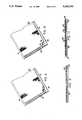
- FIG. 1is a perspective view of a cutting machine capable of being used to automatically cut a pattern piece in a web of cutting cloth material embodying the invention.
- FIG. 2is a vertical sectional partially fragmentary view showing a cutting knife in engagement with the cutting cloth web being advanced by the apparatus of FIG. 1.
- FIG. 3is a side elevational partially fragmentary sectional view showing the cutting knife in engagement with the cutting cloth web supported below it.
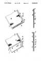
- FIG. 4is a perspective view of the cutting cloth web showing the base layer and the fabric sheet between which is interposed an adhesive layer.
- FIG. 5is a vertical sectional view through the web of FIG. 4.
- FIG. 6is a perspective view of a second embodiment of the cutting cloth web in which the fabric sheet material is held onto the base layer through the intermediary of a multiplicity of hooks.
- FIG. 7is a vertical sectional view through the web of FIG. 6.
- FIG. 8is a perspective view of the third alternative embodiment of the cutting cloth web wherein the base layer has a multiplicity of pointed projections.
- FIG. 9is a vertical sectional view through the web of FIG. 8.
- FIG. 10is a perspective view of a fourth alternative embodiment of the cutting cloth web wherein the base layer provides an elevated support surface for penetration by a reciprocating knife.
- FIG. 11is a vertical sectional view through the web of FIG. 10.
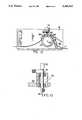
- FIG. 12is an alternative embodiment of the cutting apparatus shown in FIGS. 1-3 wherein the cutting cloth web is advanced by frictional engagement.
- FIG. 13shows the cutting element of FIG. 3 including a means for aiding in cutting of the fabric material.
- a sign machine 12is illustrated for handling and working on an associated cutting cloth web 11 of laminated construction, a layer of which includes a sheet of fabric material into which a closed shape is cut.
- the web 11is moved longitudinally of itself through the machine in the illustrated X-coordinate direction by material advancing means 2 across a work surface defined either by a platen or by the illustrated roller 20.
- a tool head 16is supported and driven by appropriate motor means (not shown) in the illustrated Y-coordinate direction on ways 13 extending transversely relative to the web 11.
- the machine 12is connected to a controller 7 herein illustrated as a separate unit, comprised of a central unit 17 having a microprocessor and appropriate memory means for storing and executing commands input to it by a key interface 25 and a monitor 26 connected to the central unit 17 for displaying a desired graphic shape onto the screen and allowing the user to see the projected shape prior to its being cut into the fabric sheet by the machine 12.
- the controller 7is connected to the machine 12 by an appropriate bus allowing it to drive the machine so as to cause coordinated movement of the web 11 relative to the tool head thereby cutting a closed shape 18 in it.
- the machine 12may be one, such as disclosed in U.S. Pat. No. 4,467,525 entitled AUTOMATED SIGN GENERATOR, issued to Logan et al. on Aug. 28, 1984, which patent being commonly assigned with the assignee of the present invention and discloses an apparatus wherein the controller, the user keyboard interface, the cutter, and the related web feeding mechanism are all integrally combined in a single unit.
- the advancing means 2includes two sprockets 14,14 (one shown) rotatably driven by appropriate drive means about a common axis of rotation 65 in response to commands issued by the controller 7.
- the sprockets 14,14are spaced apart from one another by approximately the width of the web 11, and in the one embodiment of the invention each has a series of circumferential teeth or pins 15,15 projecting radially outwardly from the axis 65.
- the pins 15,15are adapted to be received within a series of openings 5,5 extending along either side margin of the web to affect its positive movement through the machine 12.
- the openings 5,5may be ordered in a particular manner, such as disclosed in U.S. Pat. No. 4,708,919, entitled CODED WEB AND ASSOCIATED WEB HANDLING AND WORKING MACHINE issued to Kenneth Wood on Nov. 24, 1987.
- the pins 15,15being appropriately spaced from one another are received within respective ones of the series of openings 5,5 extending along either side of the web in order to effect positive driving movement of it through the machine 12.
- an associated arcuate clamp 31is provided and is connected to the machine 12 by a pivotal support arm 30 biassed toward the involved sprocket by a spring 32 drawing the clamp against the web as it is pulled through the machine.
- the web 11is readily removable from the machine, yet is held in registry with it during the cutting operation.
- the tool head 16is shown and includes a tool holder 43 and an associated tool 46 rotatable relative to the head about an axis 41 oriented substantially vertically when the tool is in the working position above the web as illustrated in FIG. 1.
- the tool head 16is pivotally mounted on the ways 13 such that the tool holder 43 is cantilevered outwardly therefrom on an arm 44 allowing the holder and its associated tool herein shown as a blade 46 to be normally urged downwards toward the web by gravity or by additional means acting to increase the downward pressing force of the blade.
- This meansmay include a variable positionable counterweight 26 mounted to the tool head 16 so as to vary the amount of downward pressure applied to the web 19 or alternatively may include a mechanical device having a variable tensioning spring mechanism for applying discrete amounts of downward force to the web through the tool holder.
- the pressure of the knife 46 on the web 11 during cuttingis controllable by such means as the counterweight 26 so that the depth of penetration of the blade can be adjusted and held at a substantially constant value.
- the depth of penetrationas explained in more detail hereinafter is such that during the cutting process the web 11 is cut through less than the full extend of its thickness.
- the tool holder 43may be caused to rotate about the axis 41 in two modes of operation.
- the first mode of operationis one such that the tip of the blade 46 is slightly offset from the axis 41 such that it swivels in response to the combined movements of the web and the tool head so as to drag the tip along a desired line of cut.
- the rotation of the tool holder 43 about the axis 41is effected by a drive belt 42 rotatably coupling the tool holder to a theta motor (not shown) angularly driving the blade 46 in response to commands issued by the controller 7.
- FIGS. 4 through 9show in further detail the construction of the web 11 of FIG. 1 made in accordance with this invention.
- the web 11is comprised of a base layer or carrier sheet 30 and a superimposed layer or sheet of fabric material 32.
- the fabric layerhas an outwardly exposed surface 38 and an inwardly directed surface 40 facing the base layer 30.
- the base layer 30has an undersurface 42 which coacts with the support roller 20 and has an oppositely facing inner surface 45 facing the fabric material sheet 32.
- a holding meansmaintaining registry of the fabric material sheet 32 with that of the underlying base or carrier sheet 30.
- this meansis comprised of a low tack pressure sensitive adhesive layer 36 releasably bonding the fabric material sheet 32 and the base layer 30 to one another.
- the adhesive layer 36may remain adhered to the base layer, such as in the case where the cut pieces are to be sewn onto another material sheet, or the adhesive may be pulled off with the involved cut fabric piece for application onto a substrate surface.
- the base layer 30may include a release surface 46 disposed on its inner surface 45 such that the adhesive layer 36 adheres more strongly to the fabric material than to the base layer 30 when the cut closed shape is separated from the length of fabric material which remains bonded to the base layer.
- the material comprising the adhesive layer 36may take many forms including being a soluble adhesive capable of being subsequently dissolved from the fabric material by application of a suitable solvent.
- the base layer 30may be formed from paper without the release surface 46 on it and the adhesive layer 36 may be a water soluble adhesive which bonds the fabric sheet 32 to the base layer 30 in its dry state but allows separation of the fabric to occur when, for example, the web is placed into a water bath after a cutting operation thereby dissolving the adhesive and separating the cut shape from the remaining fabric web length.
- the adhesive layer 36is a permanently tacky pressure sensitive adhesive having a rubber or acrylic base requiring the cut fabric shape to be weed from the unwanted fabric which remains adhered to the base layer.
- the material constituting each of the base and fabric layersis selected such that when the cut fabric shape is weed, the adhesive remains adhered to the base layer rather than to the fabric which has been cut.
- the width of the fabric sheetis somewhat less than that of the base layer 30, thus exposing the openings 5,5 along each marginal edge.
- the base layer 30is thus made from a relatively substantial piece of paper usually 80 to 100 pound weight with sufficient thickness on the order of about 8 to 10 mils to adequately resist cutting through during the cutting operation by the tool 46.
- the base layercould be formed from a less heavy or thick material having a hardness sufficient to resist cutting by the knife 46, an example of which is polycarbonate in thin sheet form.
- the holding means 34is comprised of a multiplicity of small hook-like projections 50,50 extending outwardly from the base layer 30 and towards the fabric material sheet 32.
- the fabric material used in this embodimenthas a texture sufficient to present a mat of woven fabric which has sufficient interstitial spacing between threads allowing the projecting hook elements to be trapped therein.
- the hook elements 50,50are best described as the hook parts of a VELCRO fastener which allow the fabric material 32 to be secured against movement relative to the base layer 30 yet readily allow the shape cut in the fabric sheet 32 to be separated by pulling from the base layer 30 after cutting.
- the base layer 30may be formed from a molded plastic sheet with the hooks 50,50 integrally formed therewith and having sufficient flexibility where necessary to be fed through the machine 12 along the curved path defined by the roller 20.
- the base layer 30 in a third alternative embodiment of the inventionincludes a multiplicity of projections disposed on its upper surface which grip the undersurface 40 of the fabric material 32 to hold it in registry with the base layer which supports it.
- the projections 52,52may be conical or pyramidal in shape and may be integrally formed with the base layer, such as by a plastic molding technique. They may further have a height, for example of only about one sixteenth inch or so, permitting sufficient gripping between the fabric crossings of a given cloth, for example muslin, without harming the individual fabric threads.
- the projections 52,52are arranged in rows spaced about one-sixteenth to one-eighth inch from each other and spaced about the same distance from each other in rows so as to provide about 120 equidistantly spaced projections per square inch.
- a fourth embodiment of the web 11is shown wherein the fabric material sheet 32 is supported above the base layer 30 by a multiplicity of flexible support elements 55,55 extending upwards from the base layer to provide a penetrable surface allowing for reciprocated cutting of the fabric by a blade 46'.
- Each of the elements 55,55has a head which is sizably greater in diameter than its stem portion connecting the associated head in spatial relationship to the base layer a distance equal to equally, for example about one-quarter inch.
- the spacing Dis important in this embodiment in that it allows the lower tip of the reciprocating blade 46' with each stroke to penetrate below the undersurface 40 of the fabric sheet, but not into the supporting base layer.
- the undersurface 40 of the fabric material sheetis provided with a layer of pressure sensitive adhesive which releasably holds it on the heads of the support elements 55,55.
- the support elements 55,55are preferably formed from plastic and are thus capable of being deflected out of the travel path of the blade 46'.
- FIG. 12it should be seen that the composite cutting cloth webs of FIGS. 6 through 11 are shown with marginal edge portions M,M extending along each lateral side thereof for engagement by appropriate drive means.
- the margins M,M in this embodimentdo not include the openings 5,5, but rather are adapted for advancement through the machine 12 shown in FIG. 12.
- This machineis generally identical to that shown in FIGS. 1-3, except that rather than using the pin sprockets 14,14 at each end of the roller 12, the web is supported along its entire width on the roller 20 and is frictionally driven by it along each of the margins M,M.
- clamp members 60,60are provided to maintain driving registry between roller and the base layer 30 along the margins M,M.
- margins M,Mmay alternatively include the openings 5,5 and used with the advancement system shown in FIG. 2.
- the cutting implement 46may be aided in its cutting of the fabric sheet 32 by a means 70.
- the means 70may take the form of an ultrasonic wave generator which produces a standing wave on the blade.
- the means 70may take the form of a heating element which heats the knife blade tip to further aid in its cutting.
- clamps 60,60 and 31,31are illustrated as arcuately shaped members, it is nevertheless possible to form these clamps as straight pieces coacting with a correspondingly flat support surface upon which the web is supported during cutting.
- the cutting implement 46rather than being a fixed blade may alternatively be a circular type blade which rotates with the movement of the fabric material through the machine, or may be separately rotatably driven by its own drive motor, which blade type being especially effective in use with the webs shown in FIGS. 6-11 wherein the base layer upper surface is not smooth.
Landscapes
- Life Sciences & Earth Sciences (AREA)
- Forests & Forestry (AREA)
- Engineering & Computer Science (AREA)
- Mechanical Engineering (AREA)
- Treatment Of Fiber Materials (AREA)
- Manufacturing Of Multi-Layer Textile Fabrics (AREA)
Abstract
Description
Claims (27)
Priority Applications (4)
| Application Number | Priority Date | Filing Date | Title |
|---|---|---|---|
| US07/694,792US5304410A (en) | 1991-05-02 | 1991-05-02 | Cutting cloth web having mounted backing material and related method |
| EP19920303876EP0515049B1 (en) | 1991-05-02 | 1992-04-29 | Cutting cloth web having mounted backing material and related method |
| DE69214011TDE69214011T2 (en) | 1991-05-02 | 1992-04-29 | Fabric to be cut, provided with a backing material, and related process |
| JP11373392AJPH0814072B2 (en) | 1991-05-02 | 1992-05-06 | Fabric web for cutting mold pieces |
Applications Claiming Priority (1)
| Application Number | Priority Date | Filing Date | Title |
|---|---|---|---|
| US07/694,792US5304410A (en) | 1991-05-02 | 1991-05-02 | Cutting cloth web having mounted backing material and related method |
Publications (1)
| Publication Number | Publication Date |
|---|---|
| US5304410Atrue US5304410A (en) | 1994-04-19 |
Family
ID=24790303
Family Applications (1)
| Application Number | Title | Priority Date | Filing Date |
|---|---|---|---|
| US07/694,792Expired - Fee RelatedUS5304410A (en) | 1991-05-02 | 1991-05-02 | Cutting cloth web having mounted backing material and related method |
Country Status (4)
| Country | Link |
|---|---|
| US (1) | US5304410A (en) |
| EP (1) | EP0515049B1 (en) |
| JP (1) | JPH0814072B2 (en) |
| DE (1) | DE69214011T2 (en) |
Cited By (15)
| Publication number | Priority date | Publication date | Assignee | Title |
|---|---|---|---|---|
| US5447589A (en)* | 1993-04-30 | 1995-09-05 | Rockwell International Corporation | Method for cutting fabrics, especially composite fabrics |
| US5822828A (en)* | 1996-09-13 | 1998-10-20 | Interface, Inc. | Fastener for layered floor coverings and method of fastening layers |
| USD453179S1 (en) | 2000-07-27 | 2002-01-29 | Iimak | Printer cassette |
| US20020029672A1 (en)* | 1997-03-28 | 2002-03-14 | Raney Charles C. | Web or sheet-fed apparatus having high-speed mechanism for simultaneous X, Y and theta registration |
| USD458295S1 (en) | 2000-07-27 | 2002-06-04 | Iimak | Printer cassette |
| US6526704B1 (en) | 1998-07-29 | 2003-03-04 | Interface, Inc. | Padded raised flooring panels and coverings |
| US6666122B2 (en) | 1997-03-28 | 2003-12-23 | Preco Industries, Inc. | Web or sheet-fed apparatus having high-speed mechanism for simultaneous X, Y and θ registration and method |
| USD527761S1 (en) | 2005-02-17 | 2006-09-05 | International Imaging Materials, Inc. | Printer cassette |
| US20080213529A1 (en)* | 2002-08-15 | 2008-09-04 | Interface, Inc. | System and Method for Floor Covering Installation |
| US20090094919A1 (en)* | 2000-09-19 | 2009-04-16 | Scott Graham A H | System and Method for Floor Covering Installation |
| US20110073573A1 (en)* | 2009-09-25 | 2011-03-31 | Stahl Brett A | Method and system for generating graphic elements |
| US8468772B2 (en) | 2003-08-11 | 2013-06-25 | Interface, Inc. | Carpet tiles and carpet tile installations |
| CN104358100A (en)* | 2014-10-28 | 2015-02-18 | 苏州巨康缝制机器人有限公司 | Cloth cutting knife set mechanism |
| US9691240B2 (en) | 2015-01-22 | 2017-06-27 | Interface, Inc. | Floor covering system with sensors |
| US9988760B2 (en) | 2011-05-04 | 2018-06-05 | Tandus Centiva Inc. | Modular carpet systems |
Families Citing this family (4)
| Publication number | Priority date | Publication date | Assignee | Title |
|---|---|---|---|---|
| JPH08132387A (en)* | 1994-11-04 | 1996-05-28 | Max Co Ltd | Cutting plotter |
| FR2759620B1 (en)* | 1997-02-20 | 1999-05-07 | Tecnimodern Automation Sa | DEVICE FOR PRECISE CUTTING THIN SHEET MATERIAL |
| DE102006034287B3 (en)* | 2006-07-21 | 2008-02-28 | Kraussmaffei Technologies Gmbh | Device for introducing weakening cuts into a film or skin |
| NL2010736C2 (en)* | 2013-05-01 | 2014-11-04 | Paul Norbert Manig | COMBINATION OF A JOB OF BUILDING MATERIAL AND A DEVICE FOR CUTTING A FRESH OIL. |
Citations (14)
| Publication number | Priority date | Publication date | Assignee | Title |
|---|---|---|---|---|
| US1926918A (en)* | 1933-03-03 | 1933-09-12 | Roy W Sexton | Ornamental fabric and method of production |
| GB454452A (en)* | 1935-05-02 | 1936-10-01 | James Kenyon & Son Ltd | Improvements in machine cloths or printers blankets |
| US2410884A (en)* | 1943-01-26 | 1946-11-12 | Utility Fabrics Company Inc | Composite fabric |
| US3574667A (en)* | 1968-01-05 | 1971-04-13 | Johnson & Johnson | Thermoplastic adhesive sheet |
| US3730825A (en)* | 1962-06-21 | 1973-05-01 | B Nakane | Decorative sheet material having plural adhesive layers |
| US4188445A (en)* | 1977-12-12 | 1980-02-12 | Chromatex, Inc. | Laminated fabric of polypropylene |
| US4448808A (en)* | 1982-04-15 | 1984-05-15 | Gerber Garment Technology, Inc. | Method for preparing pattern piece |
| US4467525A (en)* | 1982-07-26 | 1984-08-28 | Gerber Scientific Products, Inc. | Automated sign generator |
| US4685363A (en)* | 1985-05-22 | 1987-08-11 | Gerber Scientific, Inc. | Apparatus and method for supporting and working on sheet material |
| US4732069A (en)* | 1987-05-08 | 1988-03-22 | Gerber Scientific Products, Inc. | Knife and knife holder assembly |
| JPS63243368A (en)* | 1987-03-30 | 1988-10-11 | ダイニック株式会社 | Cutting system of cloth for making design for three-dimensional confirmation of clothing design three-dimensional |
| US4895747A (en)* | 1988-07-22 | 1990-01-23 | Minnesota Mining And Manufacturing Company | Pressure sensitive adhesive label |
| US4946320A (en)* | 1988-05-27 | 1990-08-07 | Vandermey Dean T | Routing procedure |
| US5026584A (en)* | 1987-05-29 | 1991-06-25 | Gerber Scientific Products, Inc. | Sign making web with dry adhesive layer |
Family Cites Families (3)
| Publication number | Priority date | Publication date | Assignee | Title |
|---|---|---|---|---|
| US4133235A (en)* | 1977-04-22 | 1979-01-09 | Gerber Garment Technology, Inc. | Closed loop apparatus for cutting sheet material |
| US5024020A (en)* | 1983-04-11 | 1991-06-18 | Sitton Gary L | Super setter plastic fishing hook |
| US4646911A (en)* | 1985-09-05 | 1987-03-03 | Gerber Garment Technology, Inc. | Conveyorized vacuum table for feeding sheet material |
- 1991
- 1991-05-02USUS07/694,792patent/US5304410A/ennot_activeExpired - Fee Related
- 1992
- 1992-04-29EPEP19920303876patent/EP0515049B1/ennot_activeExpired - Lifetime
- 1992-04-29DEDE69214011Tpatent/DE69214011T2/ennot_activeExpired - Fee Related
- 1992-05-06JPJP11373392Apatent/JPH0814072B2/ennot_activeExpired - Fee Related
Patent Citations (14)
| Publication number | Priority date | Publication date | Assignee | Title |
|---|---|---|---|---|
| US1926918A (en)* | 1933-03-03 | 1933-09-12 | Roy W Sexton | Ornamental fabric and method of production |
| GB454452A (en)* | 1935-05-02 | 1936-10-01 | James Kenyon & Son Ltd | Improvements in machine cloths or printers blankets |
| US2410884A (en)* | 1943-01-26 | 1946-11-12 | Utility Fabrics Company Inc | Composite fabric |
| US3730825A (en)* | 1962-06-21 | 1973-05-01 | B Nakane | Decorative sheet material having plural adhesive layers |
| US3574667A (en)* | 1968-01-05 | 1971-04-13 | Johnson & Johnson | Thermoplastic adhesive sheet |
| US4188445A (en)* | 1977-12-12 | 1980-02-12 | Chromatex, Inc. | Laminated fabric of polypropylene |
| US4448808A (en)* | 1982-04-15 | 1984-05-15 | Gerber Garment Technology, Inc. | Method for preparing pattern piece |
| US4467525A (en)* | 1982-07-26 | 1984-08-28 | Gerber Scientific Products, Inc. | Automated sign generator |
| US4685363A (en)* | 1985-05-22 | 1987-08-11 | Gerber Scientific, Inc. | Apparatus and method for supporting and working on sheet material |
| JPS63243368A (en)* | 1987-03-30 | 1988-10-11 | ダイニック株式会社 | Cutting system of cloth for making design for three-dimensional confirmation of clothing design three-dimensional |
| US4732069A (en)* | 1987-05-08 | 1988-03-22 | Gerber Scientific Products, Inc. | Knife and knife holder assembly |
| US5026584A (en)* | 1987-05-29 | 1991-06-25 | Gerber Scientific Products, Inc. | Sign making web with dry adhesive layer |
| US4946320A (en)* | 1988-05-27 | 1990-08-07 | Vandermey Dean T | Routing procedure |
| US4895747A (en)* | 1988-07-22 | 1990-01-23 | Minnesota Mining And Manufacturing Company | Pressure sensitive adhesive label |
Cited By (27)
| Publication number | Priority date | Publication date | Assignee | Title |
|---|---|---|---|---|
| US5447589A (en)* | 1993-04-30 | 1995-09-05 | Rockwell International Corporation | Method for cutting fabrics, especially composite fabrics |
| US5822828A (en)* | 1996-09-13 | 1998-10-20 | Interface, Inc. | Fastener for layered floor coverings and method of fastening layers |
| US5958540A (en)* | 1996-09-13 | 1999-09-28 | Interface, Inc. | Fastener for layered floor coverings and method of fastening layers |
| US20020029672A1 (en)* | 1997-03-28 | 2002-03-14 | Raney Charles C. | Web or sheet-fed apparatus having high-speed mechanism for simultaneous X, Y and theta registration |
| US6666122B2 (en) | 1997-03-28 | 2003-12-23 | Preco Industries, Inc. | Web or sheet-fed apparatus having high-speed mechanism for simultaneous X, Y and θ registration and method |
| US6871571B2 (en) | 1997-03-28 | 2005-03-29 | Preco Industries, Inc. | Web or sheet-fed apparatus having high-speed mechanism for simultaneous X,Y and theta registration |
| US6526704B1 (en) | 1998-07-29 | 2003-03-04 | Interface, Inc. | Padded raised flooring panels and coverings |
| USD453179S1 (en) | 2000-07-27 | 2002-01-29 | Iimak | Printer cassette |
| USD458295S1 (en) | 2000-07-27 | 2002-06-04 | Iimak | Printer cassette |
| US8381473B2 (en) | 2000-09-19 | 2013-02-26 | Interface, Inc. | System and method for floor covering installation |
| US20090094919A1 (en)* | 2000-09-19 | 2009-04-16 | Scott Graham A H | System and Method for Floor Covering Installation |
| US9402496B2 (en) | 2000-09-19 | 2016-08-02 | Interface, Inc. | System for modular tile installation |
| US8434282B2 (en) | 2000-09-19 | 2013-05-07 | Interface, Inc. | System for carpet tile installation |
| US8468771B2 (en) | 2002-08-15 | 2013-06-25 | Interface, Inc. | System and method for floor covering installation |
| US20100024329A1 (en)* | 2002-08-15 | 2010-02-04 | Interface, Inc. | System and Method for Floor Covering Installation |
| US20100176189A1 (en)* | 2002-08-15 | 2010-07-15 | Interface, Inc. | System and method for floor covering installation |
| US7757457B2 (en) | 2002-08-15 | 2010-07-20 | Interface, Inc. | System and method for floor covering installation |
| US8220221B2 (en) | 2002-08-15 | 2012-07-17 | Interface, Inc. | System and method for floor covering installation |
| US9085902B2 (en) | 2002-08-15 | 2015-07-21 | Interface, Inc. | Methods for installing modular tiles on a flooring surface |
| US20080213529A1 (en)* | 2002-08-15 | 2008-09-04 | Interface, Inc. | System and Method for Floor Covering Installation |
| US8468772B2 (en) | 2003-08-11 | 2013-06-25 | Interface, Inc. | Carpet tiles and carpet tile installations |
| USD527761S1 (en) | 2005-02-17 | 2006-09-05 | International Imaging Materials, Inc. | Printer cassette |
| US8299387B2 (en)* | 2009-09-25 | 2012-10-30 | Stahls' Inc. | Method and system for generating graphic elements |
| US20110073573A1 (en)* | 2009-09-25 | 2011-03-31 | Stahl Brett A | Method and system for generating graphic elements |
| US9988760B2 (en) | 2011-05-04 | 2018-06-05 | Tandus Centiva Inc. | Modular carpet systems |
| CN104358100A (en)* | 2014-10-28 | 2015-02-18 | 苏州巨康缝制机器人有限公司 | Cloth cutting knife set mechanism |
| US9691240B2 (en) | 2015-01-22 | 2017-06-27 | Interface, Inc. | Floor covering system with sensors |
Also Published As
| Publication number | Publication date |
|---|---|
| DE69214011T2 (en) | 1997-04-10 |
| EP0515049B1 (en) | 1996-09-25 |
| JPH0814072B2 (en) | 1996-02-14 |
| DE69214011D1 (en) | 1996-10-31 |
| JPH05132854A (en) | 1993-05-28 |
| EP0515049A1 (en) | 1992-11-25 |
Similar Documents
| Publication | Publication Date | Title |
|---|---|---|
| US5304410A (en) | Cutting cloth web having mounted backing material and related method | |
| US4512839A (en) | Multi-color sign making method and layup | |
| US5825652A (en) | Sample garment making system | |
| JP2634395B2 (en) | Automatic pattern piece cutting device and cutting method | |
| JPH065115Y2 (en) | Pattern piece making device | |
| JPH07276B2 (en) | Automatic weed device and method | |
| JPS62224598A (en) | Method and device for cutting off small piece from sheet material having irregular shape and size | |
| JPS59176022A (en) | Automatic tape lay-up method and device | |
| US5216969A (en) | Automated carpet binding apparatus | |
| JP2756327B2 (en) | Apparatus for manufacturing sections cut from material webs, such as sections for clothing | |
| JPH09510900A (en) | Blind stitch device and method for manufacturing synthetic material | |
| JPS59501783A (en) | Fabric handling equipment and methods | |
| JP3502204B2 (en) | Paper binding method and document production device | |
| JPH10513394A (en) | Locker / Patch mounting device | |
| GB2095217A (en) | Spreading aligning and smoothing fabric prior to cutting | |
| US20090266852A1 (en) | Pin Moor | |
| JPS60234689A (en) | Method and apparatus for surging work piece in sewing machine | |
| US4619211A (en) | Apparatus for producing shirring | |
| CN213866763U (en) | Auxiliary device for sewing machine | |
| WO2003024676A1 (en) | Embroidery surface treating device | |
| US6401616B1 (en) | Method and material for making a coating blanket for use in printing presses | |
| JP2005111596A (en) | Device for stacking object to be cut | |
| JP3012147U (en) | Strip work book | |
| CA2034646A1 (en) | Carpet patterning machine and method | |
| JP2001121482A (en) | Method and device for cutting sheet material |
Legal Events
| Date | Code | Title | Description |
|---|---|---|---|
| AS | Assignment | Owner name:GERBER SCIENTIFIC PRODUCTS, INC. A CORP. OF CON Free format text:ASSIGNMENT OF ASSIGNORS INTEREST.;ASSIGNOR:WEBSTER, RONALD B.;REEL/FRAME:005730/0802 Effective date:19910520 | |
| FPAY | Fee payment | Year of fee payment:4 | |
| FPAY | Fee payment | Year of fee payment:8 | |
| AS | Assignment | Owner name:ABLECO FINANCE LLC, AS COLLATERAL AGENT, NEW YORK Free format text:ASSIGNMENT FOR SECURITY;ASSIGNORS:GERBER SCIENTIFIC, INC.;GERBER SCIENTIFIC INTERNATIONAL, INC. (AS SUCCESSOR IN INTEREST TO GERBER TECHNOLOGY, INC.;GERBER SCIENTIFIC PRODUCTS, INC., A CONNECTICUT CORPORATION;AND OTHERS;REEL/FRAME:014344/0767 Effective date:20030509 | |
| AS | Assignment | Owner name:FLEET CAPITAL CORPORATION, AS AGENT, CONNECTICUT Free format text:SECURITY AGREEMENT;ASSIGNORS:GERBER SCIENTIFIC, INC.;GERBER SCIENTIFIC INTERNATIONAL, INC.;GERBER COBURN OPTICAL, INC.;AND OTHERS;REEL/FRAME:014624/0770 Effective date:20030509 | |
| REMI | Maintenance fee reminder mailed | ||
| AS | Assignment | Owner name:CITIZENS BANK OF MASSACHUSETTS, MASSACHUSETTS Free format text:INTELLECTUAL PROPERTY SECURITY AGREEMENT;ASSIGNOR:GERBER SCIENTIFIC, INC.;REEL/FRAME:017097/0668 Effective date:20051031 | |
| LAPS | Lapse for failure to pay maintenance fees | ||
| STCH | Information on status: patent discontinuation | Free format text:PATENT EXPIRED DUE TO NONPAYMENT OF MAINTENANCE FEES UNDER 37 CFR 1.362 | |
| FP | Lapsed due to failure to pay maintenance fee | Effective date:20060419 | |
| AS | Assignment | Owner name:GERBER SCIENTIFIC INC., CONNECTICUT Free format text:TERMINATION AND RELEASE OF SECURITY INTEREST IN INTELLECTUAL PROPERTY;ASSIGNOR:RBS CITIZENS, N.A. A NATIONAL BANKING ASSOCIATION AND SUCCESSOR TO CITIZENS BANK OF MASSACHUSETTS, A MASSACHUSETTS BANK;REEL/FRAME:026795/0056 Effective date:20110822 Owner name:GERBER SCIENTIFIC INTERNATIONAL INC., CONNECTICUT Free format text:TERMINATION AND RELEASE OF SECURITY INTEREST IN INTELLECTUAL PROPERTY;ASSIGNOR:RBS CITIZENS, N.A. A NATIONAL BANKING ASSOCIATION AND SUCCESSOR TO CITIZENS BANK OF MASSACHUSETTS, A MASSACHUSETTS BANK;REEL/FRAME:026795/0056 Effective date:20110822 | |
| AS | Assignment | Owner name:GERBER SCIENTIFIC, INC., CONNECTICUT Free format text:RELEASE OF ASSIGNMENT OF SECURITY - PATENTS;ASSIGNOR:ABLECO FINANCE LLC;REEL/FRAME:026962/0037 Effective date:20110922 Owner name:GERBER SCIENTIFIC INTERNATIONAL INC., CONNECTICUT Free format text:RELEASE OF ASSIGNMENT OF SECURITY - PATENTS;ASSIGNOR:ABLECO FINANCE LLC;REEL/FRAME:026962/0037 Effective date:20110922 Owner name:GERBER COBURN OPTICAL, INC., CONNECTICUT Free format text:RELEASE OF ASSIGNMENT OF SECURITY - PATENTS;ASSIGNOR:ABLECO FINANCE LLC;REEL/FRAME:026962/0037 Effective date:20110922 |