US5304272A - Method for manufacture of process printed surface covering - Google Patents
Method for manufacture of process printed surface coveringDownload PDFInfo
- Publication number
- US5304272A US5304272AUS07/743,548US74354891AUS5304272AUS 5304272 AUS5304272 AUS 5304272AUS 74354891 AUS74354891 AUS 74354891AUS 5304272 AUS5304272 AUS 5304272A
- Authority
- US
- United States
- Prior art keywords
- web
- printed
- design
- color
- printing
- Prior art date
- Legal status (The legal status is an assumption and is not a legal conclusion. Google has not performed a legal analysis and makes no representation as to the accuracy of the status listed.)
- Expired - Fee Related
Links
- 238000000034methodMethods0.000titleclaimsabstractdescription59
- 238000004519manufacturing processMethods0.000titleclaimsdescription12
- 125000000391vinyl groupChemical group[H]C([*])=C([H])[H]0.000claimsabstractdescription69
- 229920002554vinyl polymerPolymers0.000claimsabstractdescription69
- 238000007639printingMethods0.000claimsabstractdescription47
- 239000002131composite materialSubstances0.000claimsabstractdescription43
- 229920000642polymerPolymers0.000claimsabstract12
- 238000004049embossingMethods0.000claimsdescription29
- 238000010030laminatingMethods0.000claimsdescription28
- 239000003086colorantSubstances0.000claimsdescription24
- 239000004033plasticSubstances0.000claimsdescription18
- 229920003023plasticPolymers0.000claimsdescription18
- 239000000463materialSubstances0.000claimsdescription15
- 238000005520cutting processMethods0.000claimsdescription10
- 238000007646gravure printingMethods0.000claimsdescription3
- 230000000007visual effectEffects0.000claimsdescription2
- 229920005787opaque polymerPolymers0.000claims4
- 239000010410layerSubstances0.000description45
- 239000000976inkSubstances0.000description23
- 229920006266Vinyl filmPolymers0.000description7
- 230000001681protective effectEffects0.000description7
- XLYOFNOQVPJJNP-UHFFFAOYSA-NwaterSubstancesOXLYOFNOQVPJJNP-UHFFFAOYSA-N0.000description6
- 238000000137annealingMethods0.000description5
- 239000012943hotmeltSubstances0.000description5
- 239000000203mixtureSubstances0.000description5
- 239000002985plastic filmSubstances0.000description4
- 238000010586diagramMethods0.000description3
- 238000003475laminationMethods0.000description3
- 229920006255plastic filmPolymers0.000description3
- 239000007921spraySubstances0.000description3
- NIXOWILDQLNWCW-UHFFFAOYSA-Nacrylic acid groupChemical groupC(C=C)(=O)ONIXOWILDQLNWCW-UHFFFAOYSA-N0.000description2
- 238000010923batch productionMethods0.000description2
- 238000003490calenderingMethods0.000description2
- 238000010924continuous productionMethods0.000description2
- 229920001971elastomerPolymers0.000description2
- 238000010438heat treatmentMethods0.000description2
- 239000004615ingredientSubstances0.000description2
- 229920000728polyesterPolymers0.000description2
- 230000002441reversible effectEffects0.000description2
- 239000005060rubberSubstances0.000description2
- 229920002725thermoplastic elastomerPolymers0.000description2
- QTBSBXVTEAMEQO-UHFFFAOYSA-MAcetateChemical compoundCC([O-])=OQTBSBXVTEAMEQO-UHFFFAOYSA-M0.000description1
- RYGMFSIKBFXOCR-UHFFFAOYSA-NCopperChemical compound[Cu]RYGMFSIKBFXOCR-UHFFFAOYSA-N0.000description1
- JOYRKODLDBILNP-UHFFFAOYSA-NEthyl urethaneChemical compoundCCOC(N)=OJOYRKODLDBILNP-UHFFFAOYSA-N0.000description1
- 235000019738LimestoneNutrition0.000description1
- 229910000831SteelInorganic materials0.000description1
- GWEVSGVZZGPLCZ-UHFFFAOYSA-NTitan oxideChemical compoundO=[Ti]=OGWEVSGVZZGPLCZ-UHFFFAOYSA-N0.000description1
- BZHJMEDXRYGGRV-UHFFFAOYSA-NVinyl chlorideChemical compoundClC=CBZHJMEDXRYGGRV-UHFFFAOYSA-N0.000description1
- 239000010425asbestosSubstances0.000description1
- 238000004061bleachingMethods0.000description1
- 239000007844bleaching agentSubstances0.000description1
- 239000001913celluloseSubstances0.000description1
- 229920002678cellulosePolymers0.000description1
- 238000000576coating methodMethods0.000description1
- 239000000470constituentSubstances0.000description1
- 238000001816coolingMethods0.000description1
- 229920001577copolymerPolymers0.000description1
- 239000010949copperSubstances0.000description1
- 229910052802copperInorganic materials0.000description1
- 238000001125extrusionMethods0.000description1
- 239000000835fiberSubstances0.000description1
- 239000011152fibreglassSubstances0.000description1
- 239000011521glassSubstances0.000description1
- 238000007654immersionMethods0.000description1
- 239000012784inorganic fiberSubstances0.000description1
- 238000007644letterpress printingMethods0.000description1
- -1limestoneChemical compound0.000description1
- 239000006028limestoneSubstances0.000description1
- 239000012764mineral fillerSubstances0.000description1
- 238000002156mixingMethods0.000description1
- 238000012986modificationMethods0.000description1
- 230000004048modificationEffects0.000description1
- 238000010422paintingMethods0.000description1
- 239000004814polyurethaneSubstances0.000description1
- 239000000843powderSubstances0.000description1
- 230000000135prohibitive effectEffects0.000description1
- 230000033458reproductionEffects0.000description1
- 239000011369resultant mixtureSubstances0.000description1
- 229910052895riebeckiteInorganic materials0.000description1
- 229920006395saturated elastomerPolymers0.000description1
- 238000007650screen-printingMethods0.000description1
- 238000000926separation methodMethods0.000description1
- 229920002379silicone rubberPolymers0.000description1
- 239000007787solidSubstances0.000description1
- 239000010959steelSubstances0.000description1
- 239000000758substrateSubstances0.000description1
- 239000002344surface layerSubstances0.000description1
- OGIDPMRJRNCKJF-UHFFFAOYSA-Ntitanium oxideInorganic materials[Ti]=OOGIDPMRJRNCKJF-UHFFFAOYSA-N0.000description1
- 230000032258transportEffects0.000description1
- 239000002699waste materialSubstances0.000description1
- 230000037303wrinklesEffects0.000description1
Images


Classifications
- B—PERFORMING OPERATIONS; TRANSPORTING
- B32—LAYERED PRODUCTS
- B32B—LAYERED PRODUCTS, i.e. PRODUCTS BUILT-UP OF STRATA OF FLAT OR NON-FLAT, e.g. CELLULAR OR HONEYCOMB, FORM
- B32B27/00—Layered products comprising a layer of synthetic resin
- B32B27/06—Layered products comprising a layer of synthetic resin as the main or only constituent of a layer, which is next to another layer of the same or of a different material
- B32B27/08—Layered products comprising a layer of synthetic resin as the main or only constituent of a layer, which is next to another layer of the same or of a different material of synthetic resin
- B—PERFORMING OPERATIONS; TRANSPORTING
- B32—LAYERED PRODUCTS
- B32B—LAYERED PRODUCTS, i.e. PRODUCTS BUILT-UP OF STRATA OF FLAT OR NON-FLAT, e.g. CELLULAR OR HONEYCOMB, FORM
- B32B27/00—Layered products comprising a layer of synthetic resin
- B32B27/30—Layered products comprising a layer of synthetic resin comprising vinyl (co)polymers; comprising acrylic (co)polymers
- B—PERFORMING OPERATIONS; TRANSPORTING
- B41—PRINTING; LINING MACHINES; TYPEWRITERS; STAMPS
- B41F—PRINTING MACHINES OR PRESSES
- B41F19/00—Apparatus or machines for carrying out printing operations combined with other operations
- B41F19/02—Apparatus or machines for carrying out printing operations combined with other operations with embossing
- B—PERFORMING OPERATIONS; TRANSPORTING
- B32—LAYERED PRODUCTS
- B32B—LAYERED PRODUCTS, i.e. PRODUCTS BUILT-UP OF STRATA OF FLAT OR NON-FLAT, e.g. CELLULAR OR HONEYCOMB, FORM
- B32B2262/00—Composition or structural features of fibres which form a fibrous or filamentary layer or are present as additives
- B32B2262/06—Vegetal fibres
- B32B2262/062—Cellulose fibres, e.g. cotton
- B—PERFORMING OPERATIONS; TRANSPORTING
- B32—LAYERED PRODUCTS
- B32B—LAYERED PRODUCTS, i.e. PRODUCTS BUILT-UP OF STRATA OF FLAT OR NON-FLAT, e.g. CELLULAR OR HONEYCOMB, FORM
- B32B2262/00—Composition or structural features of fibres which form a fibrous or filamentary layer or are present as additives
- B32B2262/10—Inorganic fibres
- B32B2262/101—Glass fibres
- B—PERFORMING OPERATIONS; TRANSPORTING
- B32—LAYERED PRODUCTS
- B32B—LAYERED PRODUCTS, i.e. PRODUCTS BUILT-UP OF STRATA OF FLAT OR NON-FLAT, e.g. CELLULAR OR HONEYCOMB, FORM
- B32B2305/00—Condition, form or state of the layers or laminate
- B32B2305/08—Reinforcements
- B—PERFORMING OPERATIONS; TRANSPORTING
- B32—LAYERED PRODUCTS
- B32B—LAYERED PRODUCTS, i.e. PRODUCTS BUILT-UP OF STRATA OF FLAT OR NON-FLAT, e.g. CELLULAR OR HONEYCOMB, FORM
- B32B2307/00—Properties of the layers or laminate
- B32B2307/50—Properties of the layers or laminate having particular mechanical properties
- B32B2307/554—Wear resistance
- B—PERFORMING OPERATIONS; TRANSPORTING
- B32—LAYERED PRODUCTS
- B32B—LAYERED PRODUCTS, i.e. PRODUCTS BUILT-UP OF STRATA OF FLAT OR NON-FLAT, e.g. CELLULAR OR HONEYCOMB, FORM
- B32B2307/00—Properties of the layers or laminate
- B32B2307/70—Other properties
- B32B2307/75—Printability
- B—PERFORMING OPERATIONS; TRANSPORTING
- B32—LAYERED PRODUCTS
- B32B—LAYERED PRODUCTS, i.e. PRODUCTS BUILT-UP OF STRATA OF FLAT OR NON-FLAT, e.g. CELLULAR OR HONEYCOMB, FORM
- B32B2471/00—Floor coverings
- Y—GENERAL TAGGING OF NEW TECHNOLOGICAL DEVELOPMENTS; GENERAL TAGGING OF CROSS-SECTIONAL TECHNOLOGIES SPANNING OVER SEVERAL SECTIONS OF THE IPC; TECHNICAL SUBJECTS COVERED BY FORMER USPC CROSS-REFERENCE ART COLLECTIONS [XRACs] AND DIGESTS
- Y10—TECHNICAL SUBJECTS COVERED BY FORMER USPC
- Y10T—TECHNICAL SUBJECTS COVERED BY FORMER US CLASSIFICATION
- Y10T156/00—Adhesive bonding and miscellaneous chemical manufacture
- Y10T156/10—Methods of surface bonding and/or assembly therefor
- Y10T156/1002—Methods of surface bonding and/or assembly therefor with permanent bending or reshaping or surface deformation of self sustaining lamina
- Y10T156/1007—Running or continuous length work
- Y10T156/1023—Surface deformation only [e.g., embossing]
Definitions
- This inventionrelates to a printed and embossed material, suitable for use as a floor covering and a method and apparatus for making it in a continuous process. More particularly, it concerns a multilayered material combining a base layer, a preprinted vinyl layer and a wear resistant layer, which is embossed in register with the print.
- Reverse printed laminateshave been made by laminating separate sheets of calendared base material and a preprinted plastic film.
- the printed designshave been limited to random prints because of the difficulty of maintaining the desired dimensions in the preprinted plastic film in the laminate and in some cases in the base material.
- the plastic filmtends to stretch when it is being printed and subsequently dried. Since it is necessary to apply tension to the printed film during lamination in order to eliminate trapped air and wrinkles, the printed design can also be distorted during lamination.
- tilescan be formed in batch processes with designs that are in register to the cut tile by laminating preprinted plastic sheets having silk screen designs to sheets of a suitable base material. The tiles can then be hand clicked from the sheets.
- the high cost of such a batch processmakes in-register printed tile quite expensive and limits its acceptance.
- embossing stepcan be another cause of distortion, some processes are limited to embossing of a plastic surface layer that is integral with a nonplastic stable substrate such as asbestos or asphalt-saturated felt.
- the distorations which occur during printing and laminatingare minimized by printing the design on a stable base, preferably release paper, and then transferring the printed design to a hot plastic web made continuously by an extruder.
- This hot plastic webis made from a mixture of vinyl chloride or vinyl acetate copolymer, mineral filler such as limestone, and small quantities of other ingredients. Additionally, scrap material from previously formed floor tiles is ground and added to the mixture to conserve materials, reduce waste and lower costs. The resultant mixture is typically bleached with titanium oxide to lighten the color.
- a stress relieved protective wear coatis laminated to the printed web.
- the laminated webis then embossed with an engraving roll which is aligned to the laminated web by means of registration marks formed as part of the printing on the web. Additionally, these marks align a cutting means with the web so that individual tiles can be cut automatically in register with the printed and embossed pattern.
- a carrier beltsupports the hot plastic web during the printing stage, the laminating stage and the embossing stage to avoid distortion thereof.
- the method described aboveis commercially successful, it produces tiles having somewhat subdued colors because the background portion of the tile is made from a hot plastic web formed partially from scrap tiles of varying colors.
- the background coloris not white even after bleaching, and this background color can distort and dull the color of the printing on the tiles.
- tiles manufactured to have the same colorcan be inconsistent with one another if they are printed on webs of varying colors. This inconsistency results in tile in which the colors are not completely reproducible.
- a preferred embodiment of the improved processgenerally includes the following steps.
- a continuous hot plastic webis adhered to a carrier belt to reduce distortion in the web during processing as well as to maintain a constant positioning of the web.
- a preprinted white vinyl layeris laminated on the plastic web.
- a white vinylis chosen to provide a consistent and bright background as well as a smooth surface for printing.
- This vinylis at least partially opaque in that when it is laminated onto the plastic web, the background color of the web does not distort the color of the printed tile. For the purposes of simplicity, this level of opaqueness will hereinafter be referred to as "opaque”.
- a transparent wear coatis laminated onto the printed white vinyl layer to complete the composite tile material, and this composite tile material is embossed using a conventional engraved roll having raised sections which are images of the printed design. The composite material is then cut into individual tiles.
- the white vinyl layeris printed utilizing a process printing method.
- Process printingprovides a printed design having sharp, vivid colors, and can be accomplished by separating a design to be printed into a series of homogeneous color images of that design. Each of these color images is printed separately on the white vinyl layer in an overlapping manner to produce a visual effect of all of the intermediate shades of the design.
- Process printingis based on the Young-Helmholtz theory of three-color vision. According to this theory, any color can be produced by a mixture of the primary colors: blue, red and green. However, in process printing, inks are chosen so that they absorb one of the primary colors while reflecting the other two. Thus, the subtractive primary colors are utilized: magenta, yellow and cyan. Magenta absorbs green and reflects blue and red; yellow absorbs blue and reflects red and green; and cyan absorbs red and reflects green and blue. From combinations of these colors, all intermediate shades of color can be produced in process printing except black. Black is provided as a fourth printing color and is often used for shadowing in process printing.
- a color image of each of the three subtractive primary colors and blackare printed separately on the white vinyl layer to form the printed design.
- Separate engraving rollsare used to print each of the four color images onto the vinyl in a predetermined overlapping arrangement so as to produce all of the intermediate shades of the design.
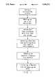
- FIG. 1is a block diagram illustrating the major steps followed in the practice of our invention
- FIG. 2is a schematic diagram of a preferred embodiment of the overall system apparatus used in the practice of our invention.
- FIG. 3is a schematic diagram of a preferred embodiment of the white vinyl printing apparatus used in the practice of our invention.
- FIG. 4is a cross-section of a base web used in the practice of our invention.
- FIG. 5is a cross-section of a base web after a printed white vinyl layer has been laminated over the base web in accordance with our invention
- FIG. 6is a cross-section of the base web and printed white vinyl layer after a transparent wear coat has been laminated over the printed white vinyl layer;
- FIG. 7is a view of an embossing roll used in the practice of our invention.
- FIG. 8is a cross-section of the base web, printed white vinyl layer and wear coat after it has been embossed in register with the print by the embossing roll of FIG. 7;
- FIG. 9is a plan view of a tile which has been embossed in register with the print using the embossing roll of FIG. 7.
- FIGS. 1 and 2illustrate a preferred method and apparatus for practicing our invention to make a vinyl tile on which a layer of printed white vinyl and a protective wear coat has been laminated onto a base web, and has been embossed in register with the print. Substantial portions of this method and apparatus are similar to those described in the '686, '074 and '959 patents and U.S. Pat. application Ser. No. 07/428,262.
- the method of making a floor tile of the inventioncomprises the following steps: forming a continuous web of vinyl, adhering this web to a carrier belt, laminating a preprinted opaque white vinyl layer onto the web, laminating a protective wear coat over the printed white vinyl layer to form a composite, embossing the composite in register with the print, and tile cutting in register with the print.
- the compositeis embossed in register with the print while maintaining proper tension in the web as it is fed into the embossing roll.
- the embossed laminateis partially annealed before cutting; and further annealed after cutting.
- Infrared heatingis used to maintain appropriate temperatures in the web, white vinyl layer and the wear coat for adhering the web to the carrier belt, laminating the opaque white vinyl layer and the protective wear coat, and pre-annealing the composite. This heating can also be accomplished by standard hot air heaters. Final annealing of the composite is accomplished in a hot air oven.
- composition of the individual layerswill be apparent to those skilled in the art from the teaching of the '686 patent; the specific temperatures for performing many of the various steps of the process will be apparent from the teaching of the '959 patent.
- FIG. 2Specific apparatus for performing the steps of FIG. 1 is illustrated in FIG. 2.
- a continuous hot melt base webis prepared by blending its constituents comprising raw ingredients and scrap from already formed tiles in blenders 20 and supplying the mix to a continuous mixer 22.
- a hot meltis continuously supplied from mixer 22 to a calendar 30 comprising a pair of rolls 32, 34 which produce a continuous hot melt base web 10.
- a doctor knife(not shown) may be used to separate base web 10 from the calendar rolls.
- FIG. 4A cross-section of a portion of base web 10 as it leaves the calendar rolls is depicted in FIG. 4. The thickness of this cross-section typically ranges from approximately 0.75 to 3.0 mm. In apparatus where a single 12-inch square tile is manufactured at a time, this cross-section is approximately 35 cm in width. Of course, other dimensions may be used in the practice of the invention.
- hot plastic web 10flows continuously onto a moving carrier belt 40 which is made of a material such that the web will adhere to the belt when the web is hot, but can be easily removed when the web is cool.
- the belt 40is made from a woven fiberglass impregnated with a silicone elastomer.
- Carrier belt 40moves base web 10 through the adhering, laminating and embossing stages, supporting the web during these processing steps.
- the beltis driven by a drive roll 46 which is driven by a conventional line shaft 48.
- a guidance system 42is utilized to guide and align the web by performing continuous adjustment on the carrier belt.
- a loop speed sensor 44positioned near calendar 30, is used to maintain the carrier belt at a constant speed as the hot melt web leaves calendar rolls 32, 34.
- a first infrared heater 50heats web 10 directly and a second infrared heater 52 heats carrier belt 40 which, in turn, heats web 10.
- the web 10enters an adhering station 60 where it is fed along belt 40 through a second calendar formed by adhering rolls 66, 67 which apply approximately 50-150 pounds per linear inch (pli) of pressure to web 10 and belt 40 as they pass therethrough. As a result, web 10 is pressed and adhered to carrier belt 40.
- the carrier beltis constructed so that the web will adhere thereto when heated, but can be easily removed when cooled. Also, we have found it useful to cool adhering roll 66 to prevent the roll from sticking to web 10.
- Adhering the web to the carrier belteliminates the problem of back-calendaring which can occur if the adhering is performed during the laminating stages.
- Back-calendaringis generally encountered where heavy gauges are passed through a set of rollers.
- By adhering the web to the carrier belt prior to laminatinglateral and transverse distortions of the web are eliminated. As a result, production line throughput is greatly increased and product quality is improved.
- the webenters a laminating station 180 that laminates a layer of preprinted opaque white vinyl 182 to web 10.
- the white vinyl layercan have any kind of design printed thereon (the printing process will be described below).
- the designis preferably one that permits tiles to be cut with the design centered in the tile so that it is in register with the edges of the tile.
- Laminating station 180comprises laminating rolls 186, 188, a supply roll 184, and guides 183, 185.
- the preprinted white vinylhas good dimensional stability to prevent stretching or other forms of distortion and is fed from supply roll 184, through guides 183, 185 and through laminating rolls 186, 188.
- an edge guidance system(not shown) is used.
- conventional splicing equipment(not shown) is used to splice individual rolls of preprinted white vinyl to form one continuous roll at supply roll 184.
- This equipmentcomprises an unwind roll stand, a splice table and a compensator that allows time to splice the printed design in register.
- the layer of white vinylis laminated by first passing it through guide 183 which aligns the preprinted vinyl with the plastic web.
- guide 183is a Fife edge guide.
- Vinyl layer 182, web 10 and carrier belt 40next pass through the nip formed by laminating rolls 186, 188.
- Infrared heater 72is positioned directly above the vinyl layer and heats the vinyl layer to 160° C., a temperature suitable for laminating the vinyl layer to the web.
- a cross-section of the composite depicting base web 10 and white vinyl layer 182is shown in FIG. 5. The thickness of the white vinyl layer is approximately 0.04 to 0.13 Mm compared to the 0.75 to 3.0 mm thickness of base web 10.
- Laminating station 80where a protective wear coat comprising a web 82 of transparent vinyl film is laminated to the printed side of white vinyl layer 182.
- Laminating station 80comprises a heated rotating drum 83, a high intensity infrared heater 93, a web guide 89, a supply roll 86, and rollers 87, 88, 91 and 92.
- the stationpreferably includes conventional splicing equipment (not shown) including an unwind roll stand, a hot splicer and a compensating device which allows time to splice the film onto supply roll 86.
- Drum 83is driven by line shaft 48 which is coupled to the drum by means of a speed control 85 such as a Specon (Reg. T.M.) speed control manufactured by Fairchild Hiller. As described in the '074 and '959 patents, the speed control 85 regulates the speed of the drum relative to that of the embossing roll and backup roll.
- a speed control 85such as a Specon (Reg. T.M.) speed control manufactured by Fairchild Hiller.
- the speed control 85regulates the speed of the drum relative to that of the embossing roll and backup roll.
- Supply roll 86provides a continuous web 82 of preformed vinyl film used as a protective wear coat.
- the vinyl filmis from 0.075 to 0.5 mm in thickness.
- Web 82passes through web guide 89 which moves web 82 in a transverse direction so that web 82 is in register with the printed web.
- web guide 89is a Fife edge guide.
- Web 82, printed white vinyl layer 182, web 10 and carrier belt 40pass through the nip formed by rotating drum 83 and roller 91, and web 82 is pressed and laminated by drum 83 atop of the printed white vinyl layer. These layers adhere to carrier belt 40 and strip away from rotating drum 83 at roller 92.
- Carrier belt 40transports the web to infrared heater 93 which heats the protective vinyl film and, therefore, the composite web.
- the temperature of web 82is raised by an infrared heater 93 so that the vinyl film is stress relieved and forms a composite 16 in which the printed white vinyl layer 182 is located between the web and wear coat 82, as depicted in FIG. 6.
- embossing station 110This station comprises an embossing roll 112, a rubber backup roll 113, and means for transverse and longitudinal positioning of the laminated web.
- embossing roll 112is an engraved or etched steel or copper roll having areas 122 that are raised above other areas 123 on the roll. Typically the difference in height between areas 122 and 123 averages about 0.15 to 0.35 mm.
- areas 122constitute an image of the design that is printed onto the composite web. Both the embossing roll and the backup roll are water cooled to prevent sticking.
- the positioning means mentioned aboveincludes two electric eyes 115, 116, a speed control means 117 and a positioning roll 118.
- Backup roll 113is driven directly by line shaft 48 so that its surface speed is the same as that of drive roll 46.
- Embossing roll 112is also driven by line shaft 48 but its speed is controlled by speed control means 117.
- the electric eyessense registration marks which are printed on the web along with the printed design.
- Electric eye 115controls positioning roll 118 which guides composite 16 in the transverse direction so that the embossing roll areas 122 are in register with the images on the composite web.
- Electric eye 116is connected to speed control 117 and controls the phase of the embossing roll so that embossing roll areas 122 are in register in the longitudinal direction with the printed pattern on the composite web.
- Specific apparatus for producing transverse and longitudinal registration with the embossing rollinclude a Fife photoelectric line control and a Bobst Champlain registron control, respectively. Numerous other devices will be apparent to
- embossing roll 112is cooled directly by a water spray 119, and this spray also cools the upper surface of composite 16.
- Water spray 119cools and sets composite 16 so that stretching of composite 16 by rolls 112 and 113 is minimized. Also, applying water to roll 112 reduces the likelihood that composite 16 will adhere to roll 112.
- Composite 16 and belt 40pass through the nip defined by embossing roll 112 and backup roll 113, and raised areas 122 of the embossing roll form corresponding depressions in the composite.
- a cross section of an embossed composite 18 as formed by this stepis shown in FIG. 8 and a plan view in FIG. 9.
- embossed composite web 18After passing through the nip formed by rolls 112 and 113, embossed composite web 18 is cooled to a temperature sufficient to allow the composite web 18 to be stripped from carrier belt 40.
- this cooling operationis accomplished by immersing composite 18 and belt 40 in a water bath 125. After immersion, excess water is removed from the web by a high velocity air knife 124 and the composite web is stripped from carrier belt 40.
- the carrier belt 40reverses direction and continues along a circular path to a position just prior to the heaters 50, 52 where it picks up the hot melt web again.
- the composite webmoves onto a conveyor belt 130 which carries it through a pre-annealing station 132 which partially removes the strains imparted by laminating and embossing. After pre-annealing, the web is again cooled. It then enters a tile cutting station 140 where it is aligned and cut into tiles in register with the pattern printed on the web.
- Tile cutting station 140comprises a tile cutter 142, electric eyes 144, 145, and equipment responsive to signals from the electric eyes for aligning the web in the transverse and longitudinal directions.
- the tilesare cut so that they are slightly oversize. They are then annealed in an annealing oven 150 to shrink them to their proper size. Finally they are cooled to ambient temperature and packaged for shipment. Scrap from the tile cutting operation is fed to a granulator 160 and returned to blenders 20 to be ground up to a powder suitable for use as a portion of the continuous base web.
- FIG. 3depicts a preferred process printing apparatus, generally designated 200, for printing a design on an opaque white vinyl web 210.
- a feed roll 212supplies a continuous web of a rigid opaque white vinyl (typically a low plastic vinyl) to the apparatus.
- the vinylis selected to have a rigidity which provides a suitable dimensional stability to allow for a low tolerance registration process for the purposes of printing thereon.
- the vinylis chosen so that the background of the printed matter is always opaque and white, thus the colors printed atop this layer remain true and reproducible. Further, the vinyl provides a smooth surface suitable for printing.
- the rigid white vinyl web 210is process printed as follows: the web is fed through a front guide 214 to maintain proper tension and alignment in the web, and is then fed through a series of four engraving rolls 216, 218, 220, 222. These engraving rolls are each supplied with a different color ink. The ink is supplied to the engraving rolls by ink baths 224, 226, 228, 230, and excess ink is removed from each roll by doctor blades 232, 234, 236, 238.
- the ink supply apparatusis well known in the art.
- the rollscan each comprise one continuous pattern, or, alternatively, a plurality of different patterns spaced apart either circumferentially or axially on the engraving roll.
- These patternscan be utilized as in conventional process printing to print on the white vinyl layer all manner of designs from the simplest such as random patterns or solid colors to the most complicated such as full color reproductions of photographs, paintings, or computer-generated art work.
- the four inksare the three subtractive primary colors: yellow, magenta (blue and red), and cyan (blue and green), as well as black.
- the design to be printedis separated into four homogenous color images corresponding to the four ink colors of the engraving rolls, and each roll is engraved with a color image pattern of one of the ink colors. This process is generally called color separation and is well known in the art.
- Each of the four color imagesis printed from its engraving roll onto the white vinyl in an overlapping manner so that when viewed together, the individual color images combine visually to produce a desired color design on the white vinyl.
- the white vinyl web 210can be printed with yellow ink by engraving roll 216; next, the web having yellow ink printed thereon can be printed with an overlapping layer of magenta ink by engraving roll 218; similarly, the web having overlapping layers of yellow ink and magenta ink printed thereon can be printed with individual overlapping layers of cyan ink and black ink by engraving rolls 220 and 222, respectively.
- each coloris applied separately to create the desired design on the web.
- Rubber support rolls 240in cooperation with the engraving rolls apply 10-60 pli of pressure to the composite web so as to make a clean print.
- the printed white vinyl web 182is fed through a rear guide 242 which is used in cooperation with front guide 214 to maintain a proper web tension, and is then wound around take-up roll 244. This roll is transferred to feed roll 184 (FIG. 2) by means of splicing (described above).
- these engraving rollsperform gravure printing wherein small depressions formed on the engraving rolls receive the specific color ink used on that roll.
- the excess inki.e. the ink which is not contained in the depressions
- the ink in the depressionsform small "dots" on the surface to be printed as that surface contacts the engraving roll in the apparatus described above.
- Intermediate tonesare produced when one of the engraving rolls prints a series of distinct dots, called halftones, of one of the subtractive primary colors and at least one other of the engraving rolls prints overlapping halftones of a different subtractive primary color adjacent to the first set of halftones. From these distinct points of color, the human eye will see a continuous color corresponding to a shade somewhere between the subtractive primary colors printed on the white vinyl.
- intermediate toneshalftones of varying areas are printed on the white vinyl, thus exposing either less or more white to create deeper or more muted shades, respectively. Further, varying intermediate tones are produced by varying the design area covered by one of the subtractive primary colors with respect to another. The area of the halftone printed on the vinyl is dictated by the depth of the depression of the engraving roll. Thus by varying the colors and areas of the halftones, all intermediate colors can be produced by this process printing method.
- a low tolerance registration procedureis critical.
- the registrationis such to maintain a +0.13 Mm printing tolerance.
- the registration procedureis accomplished by first printing registration indicia onto the white vinyl layer 182 as the design is being printed onto the vinyl layer; then, digitally controlling the position of the vinyl in both transverse and longitudinal directions by utilizing the printed registration indicia as a reference means to ensure proper placement of the individual color images on the vinyl.
- the registration apparatussenses the registration indicia, and aligns itself thereto by utilizing the digital means described above.
- these registration indiciacan be used for registration procedures in tile-forming operations other than printing, such as the above-described operations of embossing and cutting.
- the continuous webcan be utilized to form sheet vinyl surface coverings as well as individually cut tiles.
- the white vinyl layercan be replaced by any film which is compatible with the base web, e.g., opaque white polyester, acrylic, urethane, acetate or thermoplastic elastomers (TPE's).
- TPE'sthermoplastic elastomers
- the white vinyl layer or equivalentscan be reinforced with either organic fibers such as cellulose, or inorganic fibers such as glass, polyester or acrylic.
- the vinyl layer or equivalentscan have another uniform background color which is not white. In this case, the printing inks are varied to accommodate this background color so that all the colors of the design can be printed onto the tile.
- the process printingcan be performed by a variety of printing methods in addition to gravure printing. Letterpress printing, lithographic printing and even screen printing are all acceptable methods of process printing.
- the transparent wear coat laminated atop the white vinylis not always required, and can be eliminated or replaced with wear-resistant coatings such as poly-urethane.
Landscapes
- Laminated Bodies (AREA)
- Shaping Of Tube Ends By Bending Or Straightening (AREA)
Abstract
Description
Claims (9)
Priority Applications (4)
| Application Number | Priority Date | Filing Date | Title |
|---|---|---|---|
| US07/743,548US5304272A (en) | 1991-08-12 | 1991-08-12 | Method for manufacture of process printed surface covering |
| AU24492/92AAU2449292A (en) | 1991-08-12 | 1992-08-12 | Process printed surface covering and method for its manufacture |
| CA002115455ACA2115455C (en) | 1991-08-12 | 1992-08-12 | Process printed surface covering and method for its manufacture |
| PCT/US1992/006785WO1993003917A1 (en) | 1991-08-12 | 1992-08-12 | Process printed surface covering and method for its manufacture |
Applications Claiming Priority (1)
| Application Number | Priority Date | Filing Date | Title |
|---|---|---|---|
| US07/743,548US5304272A (en) | 1991-08-12 | 1991-08-12 | Method for manufacture of process printed surface covering |
Publications (1)
| Publication Number | Publication Date |
|---|---|
| US5304272Atrue US5304272A (en) | 1994-04-19 |
Family
ID=24989212
Family Applications (1)
| Application Number | Title | Priority Date | Filing Date |
|---|---|---|---|
| US07/743,548Expired - Fee RelatedUS5304272A (en) | 1991-08-12 | 1991-08-12 | Method for manufacture of process printed surface covering |
Country Status (4)
| Country | Link |
|---|---|
| US (1) | US5304272A (en) |
| AU (1) | AU2449292A (en) |
| CA (1) | CA2115455C (en) |
| WO (1) | WO1993003917A1 (en) |
Cited By (50)
| Publication number | Priority date | Publication date | Assignee | Title |
|---|---|---|---|---|
| US5405675A (en)* | 1992-12-10 | 1995-04-11 | Minnesota Mining And Manufacturing Company | Embossed multilayer film |
| US5509989A (en)* | 1993-08-19 | 1996-04-23 | Taubl; Clayton | Method for producing decorative laminate finishes |
| WO1997018949A1 (en)* | 1995-11-21 | 1997-05-29 | The Amtico Company Limited | Floor coverings |
| US5766389A (en)* | 1995-12-29 | 1998-06-16 | Kimberly-Clark Worldwide, Inc. | Disposable absorbent article having a registered graphic and process for making |
| US5818719A (en)* | 1995-12-29 | 1998-10-06 | Kimberly-Clark, Worldwide, Inc. | Apparatus for controlling the registration of two continuously moving layers of material |
| US5863632A (en)* | 1995-01-13 | 1999-01-26 | Bisker; Darcy | Decorative photographic tile and method using same |
| US5914170A (en)* | 1994-05-21 | 1999-06-22 | Pik Partner In Kunsttstoff | Process and means for producing a support part and a support part produced with it |
| US5930139A (en)* | 1996-11-13 | 1999-07-27 | Kimberly-Clark Worldwide, Inc. | Process and apparatus for registration control of material printed at machine product length |
| US5932039A (en)* | 1997-10-14 | 1999-08-03 | Kimberly-Clark Wordwide, Inc. | Process and apparatus for registering a continuously moving, treatable layer with another |
| US5964970A (en)* | 1997-10-14 | 1999-10-12 | Kimberly-Clark Worldwide, Inc. | Registration process and apparatus for continuously moving elasticized layers having multiple components |
| US6033502A (en)* | 1996-11-13 | 2000-03-07 | Kimberly-Clark Worldwide, Inc. | Process and apparatus for registering continuously moving stretchable layers |
| US6092002A (en)* | 1996-11-13 | 2000-07-18 | Kimberly-Clark Worldwide, Inc. | Variable tension process and apparatus for continuously moving layers |
| WO2001047718A1 (en)* | 1999-12-23 | 2001-07-05 | Perstorp Flooring Ab | A process for achieving decor on a surface element |
| US6303068B1 (en) | 1999-09-24 | 2001-10-16 | Milliken & Company | Process of making a cleated floor mat |
| US6319349B1 (en)* | 1999-08-02 | 2001-11-20 | Pao-Chin Lin | Plastic tiles and process for preparing the same |
| US6413618B1 (en) | 1999-05-11 | 2002-07-02 | Congoleum Corporation | Laminated glass floor tile and flooring made therefrom and method for making same |
| US6420015B1 (en) | 2000-09-27 | 2002-07-16 | Milliken & Company | Cushioned rubber floor mat and process |
| US20030093964A1 (en)* | 2001-10-16 | 2003-05-22 | Bushey Richard D. | Floor grid system |
| US6589631B1 (en) | 2000-10-04 | 2003-07-08 | Milliken & Company | Flashless rubber floor mat and method |
| US20030167717A1 (en)* | 1999-12-13 | 2003-09-11 | Faus Group, Inc. | Embossed-in-registration flooring system |
| US20030178124A1 (en)* | 1999-05-13 | 2003-09-25 | 3M Innovative Properties Company | Adhesive-backed articles |
| US20030203165A1 (en)* | 2002-04-30 | 2003-10-30 | Nobles Joy Sharon | Computer generated decorative graphic article for application to a surface |
| US20030205013A1 (en)* | 2002-05-03 | 2003-11-06 | Faus Group, Inc. | Flooring system having complementary sub-panels |
| US6652686B1 (en) | 1999-02-08 | 2003-11-25 | Kimberly-Clark Worldwide, Inc. | Processes and apparatus for making disposable absorbent articles |
| US20030234069A1 (en)* | 2000-01-21 | 2003-12-25 | Coenen Joseph Daniel | Processes and apparatus for making disposable absorbent articles |
| US20040009320A1 (en)* | 2002-05-03 | 2004-01-15 | Garcia Eugenio Cruz | Flooring system having complementary sub-panels |
| US20040009329A1 (en)* | 2002-07-11 | 2004-01-15 | Whitaker Jessie G. | Non-skid floor mat design |
| US6802164B1 (en)* | 2001-11-01 | 2004-10-12 | Ardex, L.P. | Floor with embedded image and associated method |
| US20040200165A1 (en)* | 2002-05-03 | 2004-10-14 | Faus Group, Inc | Flooring system having sub-panels |
| US20050079330A1 (en)* | 2000-12-27 | 2005-04-14 | Tanel Michael L. | Display mat with high-definition graphics |
| US20050079323A1 (en)* | 2001-01-26 | 2005-04-14 | Miller Robert J. | Textured laminate flooring |
| US20050106358A1 (en)* | 2000-08-18 | 2005-05-19 | Eshbach John R.Jr. | Three-dimensional laminate |
| US20050109445A1 (en)* | 2003-11-25 | 2005-05-26 | Pergo (Europe) Ab | Process for achieving a surface structure on a decorative laminate |
| US20050147800A1 (en)* | 2003-03-21 | 2005-07-07 | Hunter Douglas Inc. | Pearlescent honeycomb material and method for fabricating same |
| US20050210808A1 (en)* | 2004-03-23 | 2005-09-29 | Building Materials Investment Corporation | Building membrane |
| US20060005498A1 (en)* | 2004-07-07 | 2006-01-12 | Vincente Sabater | Flooring system having sub-panels with complementary edge patterns |
| US7045193B2 (en) | 2000-12-27 | 2006-05-16 | Michael L. Tanel | Display mat with high-definition graphics |
| US20060191222A1 (en)* | 2005-02-28 | 2006-08-31 | Vincente Sabater | Flooring system having large floor pattern |
| US20060194015A1 (en)* | 2004-11-05 | 2006-08-31 | Vincente Sabater | Flooring system with slant pattern |
| US20070175137A1 (en)* | 2005-12-29 | 2007-08-02 | Tru Woods Limited. | Floor plank |
| US20090260756A1 (en)* | 2008-04-18 | 2009-10-22 | Alf Martin Book | Method And Apparatus For Applying Heat Activated Transfer Adhesives |
| US20090301649A1 (en)* | 2005-10-20 | 2009-12-10 | Man Roland Druckmaschinen Ag | Manufacturing method for packaging and advertising means |
| US20100068385A1 (en)* | 2008-09-16 | 2010-03-18 | Fernback Katharine C | Sheet goods having a large repeat length and tile with numerous patterns |
| US7836649B2 (en) | 2002-05-03 | 2010-11-23 | Faus Group, Inc. | Flooring system having microbevels |
| US8201377B2 (en) | 2004-11-05 | 2012-06-19 | Faus Group, Inc. | Flooring system having multiple alignment points |
| US8875460B2 (en) | 1999-11-05 | 2014-11-04 | Faus Group, Inc. | Direct laminated floor |
| US20170274702A1 (en)* | 2013-07-19 | 2017-09-28 | Maax Bath Inc. | Decorative panel having a digitally printed pattern |
| US20190217524A1 (en)* | 2018-01-15 | 2019-07-18 | Ting Yi LIOU | Plastic flooring having registration system |
| WO2023191697A1 (en)* | 2022-03-31 | 2023-10-05 | Välinge Innovation AB | A method to produce a laminated substrate and such a laminated substrate |
| US12232664B2 (en) | 2021-03-30 | 2025-02-25 | American Bath Group, Llc | Shower assembly with integrated water collection and dispersion |
Families Citing this family (2)
| Publication number | Priority date | Publication date | Assignee | Title |
|---|---|---|---|---|
| DK0960024T4 (en)* | 1997-12-11 | 2006-09-25 | Teich Ag | Process for producing partially embossed lid elements for containers and device for carrying out the method |
| DE102014101554A1 (en)* | 2013-10-16 | 2015-04-16 | Olbrich Gmbh | Method and device for producing a register-embossed, in particular laminated, composite material |
Citations (11)
| Publication number | Priority date | Publication date | Assignee | Title |
|---|---|---|---|---|
| US3465384A (en)* | 1967-02-08 | 1969-09-09 | American Biltrite Rubber Co | Apparatus for registration of plastic web |
| US4225374A (en)* | 1978-04-20 | 1980-09-30 | Armstrong Cork Company | Decorative flooring |
| US4305768A (en)* | 1978-04-10 | 1981-12-15 | John F. Lontz Associates, Inc. | Laminating process for producing high fidelity color prints |
| US4312686A (en)* | 1980-02-11 | 1982-01-26 | American Biltrite Inc. | Printed and embossed floor covering and method and apparatus for its manufacture |
| US4483732A (en)* | 1983-08-04 | 1984-11-20 | Congoleum Corporation | Process for preparing high reflectivity decorative surface coverings |
| US4552606A (en)* | 1983-03-07 | 1985-11-12 | Armstrong World Industries, Inc. | Flotation method for orienting chips in the manufacture of surface covering |
| US4612074A (en)* | 1983-08-24 | 1986-09-16 | American Biltrite Inc. | Method for manufacturing a printed and embossed floor covering |
| US4678528A (en)* | 1985-03-05 | 1987-07-07 | American Biltrite, Inc. | Method and apparatus for making a printed and embossed floor covering using a cast wear layer |
| US4773959A (en)* | 1983-08-24 | 1988-09-27 | American Biltrite, Inc. | Apparatus for the manufacture of printed and embossed floor covering |
| US4804429A (en)* | 1987-12-11 | 1989-02-14 | Armstrong World Industries, Inc. | Method of forming a floor tile on a drum |
| US4844849A (en)* | 1985-02-21 | 1989-07-04 | Congoleum Corporation | Method of making embossed decorative sheets |
- 1991
- 1991-08-12USUS07/743,548patent/US5304272A/ennot_activeExpired - Fee Related
- 1992
- 1992-08-12AUAU24492/92Apatent/AU2449292A/ennot_activeAbandoned
- 1992-08-12WOPCT/US1992/006785patent/WO1993003917A1/enactiveApplication Filing
- 1992-08-12CACA002115455Apatent/CA2115455C/ennot_activeExpired - Fee Related
Patent Citations (11)
| Publication number | Priority date | Publication date | Assignee | Title |
|---|---|---|---|---|
| US3465384A (en)* | 1967-02-08 | 1969-09-09 | American Biltrite Rubber Co | Apparatus for registration of plastic web |
| US4305768A (en)* | 1978-04-10 | 1981-12-15 | John F. Lontz Associates, Inc. | Laminating process for producing high fidelity color prints |
| US4225374A (en)* | 1978-04-20 | 1980-09-30 | Armstrong Cork Company | Decorative flooring |
| US4312686A (en)* | 1980-02-11 | 1982-01-26 | American Biltrite Inc. | Printed and embossed floor covering and method and apparatus for its manufacture |
| US4552606A (en)* | 1983-03-07 | 1985-11-12 | Armstrong World Industries, Inc. | Flotation method for orienting chips in the manufacture of surface covering |
| US4483732A (en)* | 1983-08-04 | 1984-11-20 | Congoleum Corporation | Process for preparing high reflectivity decorative surface coverings |
| US4612074A (en)* | 1983-08-24 | 1986-09-16 | American Biltrite Inc. | Method for manufacturing a printed and embossed floor covering |
| US4773959A (en)* | 1983-08-24 | 1988-09-27 | American Biltrite, Inc. | Apparatus for the manufacture of printed and embossed floor covering |
| US4844849A (en)* | 1985-02-21 | 1989-07-04 | Congoleum Corporation | Method of making embossed decorative sheets |
| US4678528A (en)* | 1985-03-05 | 1987-07-07 | American Biltrite, Inc. | Method and apparatus for making a printed and embossed floor covering using a cast wear layer |
| US4804429A (en)* | 1987-12-11 | 1989-02-14 | Armstrong World Industries, Inc. | Method of forming a floor tile on a drum |
Cited By (94)
| Publication number | Priority date | Publication date | Assignee | Title |
|---|---|---|---|---|
| US5405675A (en)* | 1992-12-10 | 1995-04-11 | Minnesota Mining And Manufacturing Company | Embossed multilayer film |
| US5509989A (en)* | 1993-08-19 | 1996-04-23 | Taubl; Clayton | Method for producing decorative laminate finishes |
| US5914170A (en)* | 1994-05-21 | 1999-06-22 | Pik Partner In Kunsttstoff | Process and means for producing a support part and a support part produced with it |
| US5863632A (en)* | 1995-01-13 | 1999-01-26 | Bisker; Darcy | Decorative photographic tile and method using same |
| US6007892A (en)* | 1995-11-21 | 1999-12-28 | The Amtico Company Limited | Floor coverings |
| WO1997018949A1 (en)* | 1995-11-21 | 1997-05-29 | The Amtico Company Limited | Floor coverings |
| US6589379B1 (en) | 1995-11-21 | 2003-07-08 | Ivor C. Harwood | Floor coverings |
| US6103044A (en)* | 1995-11-21 | 2000-08-15 | The Amtico Company Limited | Floor coverings |
| US5766389A (en)* | 1995-12-29 | 1998-06-16 | Kimberly-Clark Worldwide, Inc. | Disposable absorbent article having a registered graphic and process for making |
| US5818719A (en)* | 1995-12-29 | 1998-10-06 | Kimberly-Clark, Worldwide, Inc. | Apparatus for controlling the registration of two continuously moving layers of material |
| US5980087A (en)* | 1995-12-29 | 1999-11-09 | Kimberly-Clark Worldwide, Inc. | Apparatus for controlling the registration of two continuously moving layers of material and an article made thereby |
| US5930139A (en)* | 1996-11-13 | 1999-07-27 | Kimberly-Clark Worldwide, Inc. | Process and apparatus for registration control of material printed at machine product length |
| US6092002A (en)* | 1996-11-13 | 2000-07-18 | Kimberly-Clark Worldwide, Inc. | Variable tension process and apparatus for continuously moving layers |
| US6245168B1 (en) | 1996-11-13 | 2001-06-12 | Kimberly-Clark Worldwide, Inc. | Process and apparatus for registering continuously moving stretchable layers |
| US6033502A (en)* | 1996-11-13 | 2000-03-07 | Kimberly-Clark Worldwide, Inc. | Process and apparatus for registering continuously moving stretchable layers |
| US5964970A (en)* | 1997-10-14 | 1999-10-12 | Kimberly-Clark Worldwide, Inc. | Registration process and apparatus for continuously moving elasticized layers having multiple components |
| US5932039A (en)* | 1997-10-14 | 1999-08-03 | Kimberly-Clark Wordwide, Inc. | Process and apparatus for registering a continuously moving, treatable layer with another |
| US6652686B1 (en) | 1999-02-08 | 2003-11-25 | Kimberly-Clark Worldwide, Inc. | Processes and apparatus for making disposable absorbent articles |
| US6413618B1 (en) | 1999-05-11 | 2002-07-02 | Congoleum Corporation | Laminated glass floor tile and flooring made therefrom and method for making same |
| US20080105356A1 (en)* | 1999-05-13 | 2008-05-08 | 3M Innovative Properties Company | Adhesive-backed articles |
| US20060188704A1 (en)* | 1999-05-13 | 2006-08-24 | 3M Innovative Properties Company | Adhesive-backed articles |
| US20030178124A1 (en)* | 1999-05-13 | 2003-09-25 | 3M Innovative Properties Company | Adhesive-backed articles |
| US9085121B2 (en) | 1999-05-13 | 2015-07-21 | 3M Innovative Properties Company | Adhesive-backed articles |
| US6319349B1 (en)* | 1999-08-02 | 2001-11-20 | Pao-Chin Lin | Plastic tiles and process for preparing the same |
| WO2001021875A3 (en)* | 1999-09-24 | 2001-10-18 | Milliken & Co | Cleat-forming conveyor belt for the manufacture of anti-creep floor mats |
| US6787215B1 (en) | 1999-09-24 | 2004-09-07 | Milliken & Company | Cleat-forming woven fabric article for the manufacture of anti-creep floor mats |
| US6709728B2 (en) | 1999-09-24 | 2004-03-23 | Milliken & Company | Cleated anti-creep floor mats |
| US6520763B1 (en) | 1999-09-24 | 2003-02-18 | Milliken & Company | Apparatus for forming cleated floor mat |
| US6303068B1 (en) | 1999-09-24 | 2001-10-16 | Milliken & Company | Process of making a cleated floor mat |
| US8875460B2 (en) | 1999-11-05 | 2014-11-04 | Faus Group, Inc. | Direct laminated floor |
| US20030167717A1 (en)* | 1999-12-13 | 2003-09-11 | Faus Group, Inc. | Embossed-in-registration flooring system |
| US8209928B2 (en) | 1999-12-13 | 2012-07-03 | Faus Group | Embossed-in-registration flooring system |
| US8944543B2 (en) | 1999-12-23 | 2015-02-03 | Pergo (Europe) Ab | Process for the manufacturing of surface elements |
| WO2001047717A1 (en)* | 1999-12-23 | 2001-07-05 | Perstorp Flooring Ab | A process for achieving decor on surface elements |
| WO2001047718A1 (en)* | 1999-12-23 | 2001-07-05 | Perstorp Flooring Ab | A process for achieving decor on a surface element |
| US20030207083A1 (en)* | 1999-12-23 | 2003-11-06 | Krister Hansson | Process for the manufacturing of surface elements |
| US9656476B2 (en) | 1999-12-23 | 2017-05-23 | Pergo (Europe) Ab | Process for the manufacturing of surface elements |
| US9636923B2 (en) | 1999-12-23 | 2017-05-02 | Pergo (Europe) Ab | Process for the manufacturing of surface elements |
| US9409412B2 (en) | 1999-12-23 | 2016-08-09 | Pergo (Europe) Ab | Process for the manufacturing of surface elements |
| US6565919B1 (en) | 1999-12-23 | 2003-05-20 | Pergo (Europe) Ab | Process for the manufacturing of surface elements |
| WO2001048333A1 (en)* | 1999-12-23 | 2001-07-05 | Perstorp Flooring Ab | A process for the manufacturing of surface elements |
| US9636922B2 (en) | 1999-12-23 | 2017-05-02 | Pergo (Europe) Ab | Process for the manufacturing of surface elements |
| US8950138B2 (en) | 1999-12-23 | 2015-02-10 | Pergo (Europe) Ab | Process for the manufacturing of surface elements |
| US9321299B2 (en) | 1999-12-23 | 2016-04-26 | Pergo (Europe) Ab | Process for the manufacturing of surface elements |
| US10464339B2 (en) | 1999-12-23 | 2019-11-05 | Pergo (Europe) Ab | Process for the manufacturing of surface elements |
| US6986820B2 (en) | 2000-01-21 | 2006-01-17 | Kimberly-Clark Worldwide, Inc. | Processes and apparatus for making disposable absorbent articles |
| US20030234069A1 (en)* | 2000-01-21 | 2003-12-25 | Coenen Joseph Daniel | Processes and apparatus for making disposable absorbent articles |
| US20050106358A1 (en)* | 2000-08-18 | 2005-05-19 | Eshbach John R.Jr. | Three-dimensional laminate |
| US6420015B1 (en) | 2000-09-27 | 2002-07-16 | Milliken & Company | Cushioned rubber floor mat and process |
| US6589631B1 (en) | 2000-10-04 | 2003-07-08 | Milliken & Company | Flashless rubber floor mat and method |
| US20050079330A1 (en)* | 2000-12-27 | 2005-04-14 | Tanel Michael L. | Display mat with high-definition graphics |
| US7045193B2 (en) | 2000-12-27 | 2006-05-16 | Michael L. Tanel | Display mat with high-definition graphics |
| US20050079323A1 (en)* | 2001-01-26 | 2005-04-14 | Miller Robert J. | Textured laminate flooring |
| US7243469B2 (en) | 2001-01-26 | 2007-07-17 | Columbia Insurance Company | Textured laminate flooring |
| US20030093964A1 (en)* | 2001-10-16 | 2003-05-22 | Bushey Richard D. | Floor grid system |
| US6802164B1 (en)* | 2001-11-01 | 2004-10-12 | Ardex, L.P. | Floor with embedded image and associated method |
| US20030203165A1 (en)* | 2002-04-30 | 2003-10-30 | Nobles Joy Sharon | Computer generated decorative graphic article for application to a surface |
| US8112958B2 (en) | 2002-05-03 | 2012-02-14 | Faus Group | Flooring system having complementary sub-panels |
| US20110203207A1 (en)* | 2002-05-03 | 2011-08-25 | Eugenio Cruz Garcia | Flooring system having complementary sub-panels |
| US20030205013A1 (en)* | 2002-05-03 | 2003-11-06 | Faus Group, Inc. | Flooring system having complementary sub-panels |
| US20040009320A1 (en)* | 2002-05-03 | 2004-01-15 | Garcia Eugenio Cruz | Flooring system having complementary sub-panels |
| US8448400B2 (en) | 2002-05-03 | 2013-05-28 | Faus Group | Flooring system having complementary sub-panels |
| US7836648B2 (en) | 2002-05-03 | 2010-11-23 | Faus Group | Flooring system having complementary sub-panels |
| US7836649B2 (en) | 2002-05-03 | 2010-11-23 | Faus Group, Inc. | Flooring system having microbevels |
| US20110094179A1 (en)* | 2002-05-03 | 2011-04-28 | Faus Group | Flooring system having microbevels |
| US20040200165A1 (en)* | 2002-05-03 | 2004-10-14 | Faus Group, Inc | Flooring system having sub-panels |
| US8181407B2 (en) | 2002-05-03 | 2012-05-22 | Faus Group | Flooring system having sub-panels |
| US8099919B2 (en) | 2002-05-03 | 2012-01-24 | Faus Group | Flooring system having microbevels |
| US6933036B2 (en) | 2002-07-11 | 2005-08-23 | Textron Inc. | Non-skid floor mat design |
| US20040009329A1 (en)* | 2002-07-11 | 2004-01-15 | Whitaker Jessie G. | Non-skid floor mat design |
| US20050147800A1 (en)* | 2003-03-21 | 2005-07-07 | Hunter Douglas Inc. | Pearlescent honeycomb material and method for fabricating same |
| US20050109445A1 (en)* | 2003-11-25 | 2005-05-26 | Pergo (Europe) Ab | Process for achieving a surface structure on a decorative laminate |
| US9446568B2 (en)* | 2004-03-23 | 2016-09-20 | Building Materials Investment Corporation | Building membrane |
| US20050210808A1 (en)* | 2004-03-23 | 2005-09-29 | Building Materials Investment Corporation | Building membrane |
| US20060005498A1 (en)* | 2004-07-07 | 2006-01-12 | Vincente Sabater | Flooring system having sub-panels with complementary edge patterns |
| US20060194015A1 (en)* | 2004-11-05 | 2006-08-31 | Vincente Sabater | Flooring system with slant pattern |
| US8201377B2 (en) | 2004-11-05 | 2012-06-19 | Faus Group, Inc. | Flooring system having multiple alignment points |
| US20060191222A1 (en)* | 2005-02-28 | 2006-08-31 | Vincente Sabater | Flooring system having large floor pattern |
| US20090301649A1 (en)* | 2005-10-20 | 2009-12-10 | Man Roland Druckmaschinen Ag | Manufacturing method for packaging and advertising means |
| US20070175137A1 (en)* | 2005-12-29 | 2007-08-02 | Tru Woods Limited. | Floor plank |
| US7322159B2 (en)* | 2005-12-29 | 2008-01-29 | Tru Woods Limited | Floor plank |
| US7934531B2 (en)* | 2008-04-18 | 2011-05-03 | Brady Worldwide, Inc. | Method and apparatus for applying heat activated transfer adhesives |
| US20090260756A1 (en)* | 2008-04-18 | 2009-10-22 | Alf Martin Book | Method And Apparatus For Applying Heat Activated Transfer Adhesives |
| CN102216085A (en)* | 2008-09-16 | 2011-10-12 | 阿姆斯特郎世界工业公司 | Sheets with long repeat lengths and bricks in a variety of patterns |
| US9062464B2 (en) | 2008-09-16 | 2015-06-23 | Awi Licensing Company | Sheet goods having a large repeat length and tile with numerous patterns |
| US20100068385A1 (en)* | 2008-09-16 | 2010-03-18 | Fernback Katharine C | Sheet goods having a large repeat length and tile with numerous patterns |
| US8496779B2 (en)* | 2008-09-16 | 2013-07-30 | Armstrong World Industries, Inc. | Sheet goods having a large repeat length and tile with numerous patterns |
| US20170274702A1 (en)* | 2013-07-19 | 2017-09-28 | Maax Bath Inc. | Decorative panel having a digitally printed pattern |
| US10933686B2 (en)* | 2013-07-19 | 2021-03-02 | Maax Bath Inc. | Decorative panel having a digitally printed pattern |
| US20190217524A1 (en)* | 2018-01-15 | 2019-07-18 | Ting Yi LIOU | Plastic flooring having registration system |
| US10695971B2 (en)* | 2018-01-15 | 2020-06-30 | Ting Yi LIOU | Plastic flooring having registration system |
| US12232664B2 (en) | 2021-03-30 | 2025-02-25 | American Bath Group, Llc | Shower assembly with integrated water collection and dispersion |
| WO2023191697A1 (en)* | 2022-03-31 | 2023-10-05 | Välinge Innovation AB | A method to produce a laminated substrate and such a laminated substrate |
| US20230311471A1 (en)* | 2022-03-31 | 2023-10-05 | Välinge Innovation AB | Method to produce a laminated substrate and such a laminated substrate |
Also Published As
| Publication number | Publication date |
|---|---|
| WO1993003917A1 (en) | 1993-03-04 |
| CA2115455A1 (en) | 1993-03-04 |
| AU2449292A (en) | 1993-03-16 |
| CA2115455C (en) | 1999-05-25 |
Similar Documents
| Publication | Publication Date | Title |
|---|---|---|
| US5304272A (en) | Method for manufacture of process printed surface covering | |
| CA2071922C (en) | Method and apparatus for the manufacture of printed and embossed floor covering | |
| US4612074A (en) | Method for manufacturing a printed and embossed floor covering | |
| US4312686A (en) | Printed and embossed floor covering and method and apparatus for its manufacture | |
| US4773959A (en) | Apparatus for the manufacture of printed and embossed floor covering | |
| US4678528A (en) | Method and apparatus for making a printed and embossed floor covering using a cast wear layer | |
| CA1229543A (en) | Printed and embossed floor covering and method and apparatus for its manufacture | |
| CA1123565A (en) | Decorative flooring | |
| US6249297B1 (en) | Process for continuously printing a plastic film, device for carrying out the process and printed plastic film obtained by the process | |
| JPH0839669A (en) | Pattern tuning embossing register adjustment method | |
| EP1711569A1 (en) | Method of producing colored graphic marking films | |
| JPS6257509B2 (en) | ||
| US20010033918A1 (en) | Methods for making decorative overlays, foils and decorative moldings | |
| US20120313288A1 (en) | Method and apparatus for manufacturing a film with markings | |
| JP2010155051A (en) | Colored design transferring apparatus for fastener and colored design transferring apparatus for strip-shaped object | |
| CA1153293A (en) | Printed and embossed floor covering and method for its manufacture | |
| JP2002515616A (en) | Lenticular lens printing process | |
| CN107415455A (en) | A kind of printing machine | |
| EP0825038B1 (en) | Method of manufacturing a multicoloured synthetic resin product with the appearance and texture of lace | |
| KR200274118Y1 (en) | Appartus for pring 2-color foil to cloth | |
| CN214395997U (en) | Digital high-pressure printing all-in-one machine | |
| KR20020076915A (en) | A process of producing a 3d stereo flash bright color plastic sheet | |
| EP0852542B1 (en) | Improved transparent measuring device and method of making | |
| JPH0725134B2 (en) | Embossing method | |
| SE435356B (en) | PROCEDURE FOR MANUFACTURING A PREPARATION AND RELIEF-MASTERED PLASTIC MATERIAL |
Legal Events
| Date | Code | Title | Description |
|---|---|---|---|
| AS | Assignment | Owner name:AMERICAN BILTRITE, INC., NEW JERSEY Free format text:ASSIGNMENT OF ASSIGNORS INTEREST.;ASSIGNORS:ROHRBACKER, PETER J.;DICKSON, MARTIN J.;REEL/FRAME:005812/0222 Effective date:19910808 | |
| AS | Assignment | Owner name:CONGOLEUM CORPORATION, NEW JERSEY Free format text:ASSIGNMENT OF ASSIGNORS INTEREST.;ASSIGNOR:RESILIENT HOLDINGS INCORPORATED;REEL/FRAME:006485/0358 Effective date:19930311 Owner name:CONGOLEUM HOLDINGS INCORPORATED, NEW YORK Free format text:ASSIGNMENT OF ASSIGNORS INTEREST.;ASSIGNOR:AMERICAN BILTRITE INC.;REEL/FRAME:006485/0342 Effective date:19930311 Owner name:RESILIENT HOLDINGS INCORPORATED, NEW YORK Free format text:ASSIGNMENT OF ASSIGNORS INTEREST.;ASSIGNOR:CONGOLEUM HOLDINGS INCORPORATED;REEL/FRAME:006485/0350 Effective date:19930311 | |
| AS | Assignment | Owner name:CIT GROUP/ BUSINESS CREDIT, INC., THE, NEW YORK Free format text:SECURITY INTEREST;ASSIGNOR:CONGOLEUM CORPORATION;REEL/FRAME:006531/0364 Effective date:19930311 | |
| AS | Assignment | Owner name:CONGOLEUM CORPORATION, NEW JERSEY Free format text:ASSIGNMENT OF ASSIGNORS INTEREST;ASSIGNOR:AMERICAN BILTRITE, INC.;REEL/FRAME:007061/0004 Effective date:19940629 | |
| AS | Assignment | Owner name:CONGOLEUM CORPORATION, NEW JERSEY Free format text:TERMINATION OF SECURITY AGREEMENT;ASSIGNOR:CIT GROUP/BUSINESS CREDIT, INC., THE, AS AGENT;REEL/FRAME:007205/0471 Effective date:19941026 | |
| FPAY | Fee payment | Year of fee payment:4 | |
| LAPS | Lapse for failure to pay maintenance fees | ||
| STCH | Information on status: patent discontinuation | Free format text:PATENT EXPIRED DUE TO NONPAYMENT OF MAINTENANCE FEES UNDER 37 CFR 1.362 | |
| FP | Lapsed due to failure to pay maintenance fee | Effective date:20020419 |