US5304218A - Cardiac lead implanting arrangement and method - Google Patents
Cardiac lead implanting arrangement and methodDownload PDFInfo
- Publication number
- US5304218A US5304218AUS07/892,177US89217792AUS5304218AUS 5304218 AUS5304218 AUS 5304218AUS 89217792 AUS89217792 AUS 89217792AUS 5304218 AUS5304218 AUS 5304218A
- Authority
- US
- United States
- Prior art keywords
- guide wire
- lead
- electrode
- predetermined path
- implanted
- Prior art date
- Legal status (The legal status is an assumption and is not a legal conclusion. Google has not performed a legal analysis and makes no representation as to the accuracy of the status listed.)
- Expired - Fee Related
Links
- 238000000034methodMethods0.000titleclaimsabstractdescription17
- 230000000747cardiac effectEffects0.000titledescription3
- 238000002513implantationMethods0.000claimsabstractdescription62
- 238000001990intravenous administrationMethods0.000claimsabstractdescription17
- 239000000463materialSubstances0.000claimsabstractdescription17
- 210000003462veinAnatomy0.000claimsdescription32
- 210000003748coronary sinusAnatomy0.000claimsdescription31
- 210000005245right atriumAnatomy0.000claimsdescription18
- 210000002620vena cava superiorAnatomy0.000claimsdescription11
- 210000005241right ventricleAnatomy0.000description12
- 230000000694effectsEffects0.000description9
- 230000001746atrial effectEffects0.000description6
- 210000002837heart atriumAnatomy0.000description6
- 210000005246left atriumAnatomy0.000description5
- 210000005240left ventricleAnatomy0.000description5
- 206010003658Atrial FibrillationDiseases0.000description2
- 210000001367arteryAnatomy0.000description2
- 210000005242cardiac chamberAnatomy0.000description2
- 238000012986modificationMethods0.000description2
- 230000004048modificationEffects0.000description2
- 230000002861ventricularEffects0.000description2
- 102100026827Protein associated with UVRAG as autophagy enhancerHuman genes0.000description1
- 101710102978Protein associated with UVRAG as autophagy enhancerProteins0.000description1
- 230000003187abdominal effectEffects0.000description1
- 210000003484anatomyAnatomy0.000description1
- 238000005452bendingMethods0.000description1
- 239000012141concentrateSubstances0.000description1
- 239000004020conductorSubstances0.000description1
- 230000006378damageEffects0.000description1
- 239000007943implantSubstances0.000description1
- 238000009413insulationMethods0.000description1
- 238000007920subcutaneous administrationMethods0.000description1
- 230000000451tissue damageEffects0.000description1
- 231100000827tissue damageToxicity0.000description1
- 230000002792vascularEffects0.000description1
Images


Classifications
- A—HUMAN NECESSITIES
- A61—MEDICAL OR VETERINARY SCIENCE; HYGIENE
- A61N—ELECTROTHERAPY; MAGNETOTHERAPY; RADIATION THERAPY; ULTRASOUND THERAPY
- A61N1/00—Electrotherapy; Circuits therefor
- A61N1/02—Details
- A61N1/04—Electrodes
- A61N1/05—Electrodes for implantation or insertion into the body, e.g. heart electrode
- A61N1/056—Transvascular endocardial electrode systems
Definitions
- the present inventionrelates to an arrangement to facilitate the implantation of an electrode at an implantation site within the human body.
- the present inventionis more particularly directed to such an arrangement for implanting an electrode of a cardiac lead within a coronary vein of the human heart.
- the practice of implanting cardiac pacemakers or defibrillators in the body of a human patientgenerally includes the implantation of one or more electrodes in, on, or near the heart. Such electrodes are used to either sense heart activity or deliver pacing or cardioverting electrical energy to the heart. Often, an electrode may be utilized for both functions.
- Pacemakers and defibrillatorsgenerally include electrical components including sense amplifiers, a pulse generator, and a battery which are housed within a sealed enclosure.
- the enclosuresare generally implanted in a subcutaneous pocket usually located in the subclavicular region in adults or in the abdominal region in children.
- the pacemakers or defibrillatorsare generally coupled to the heart through one or more leads which include the aforementioned electrodes.
- the leadsinclude a proximal end having a connector which connects to a terminal of the pacer or defibrillator enclosure and a distal end which carries the electrode. Some leads may include more than one electrode.
- the body of a leadis generally composed of conductive wires surrounded by insulation. The conductive wires couple the lead connector to the lead electrode or electrodes.
- An endocardial leadis a lead which is implanted within a chamber of the heart so that the distal electrode of the lead can be fixed to the inner wall of a heart chamber.
- a transvenous approachis utilized wherein the lead is inserted into and passed through the subclavian, jugular, or cephalic vein and into the appropriate heart chamber.
- An intravenous leadis a lead which is implanted within a coronary vein such as the great vein.
- intravenous leadis particularly useful in an implantable atrial defibrillator application.
- the distal end of the intravenous lead there disclosedis passed through the superior vena cava, the right atrium, the valve of the coronary sinus, the coronary sinus, and into a coronary vein communicating with the coronary sinus, such as the great vein.
- the intravenous leadincludes a distal or tip electrode which, when residing in the aforementioned coronary vein, such as the great vein, is closely adjacent the left ventricle of the heart for sensing ventricular activity of the heart.
- the leadfurther includes an elongated proximal electrode which is spaced from the distal or tip electrode so that when the tip electrode is within the coronary vein, the proximal electrode resides in the coronary sinus above the left ventricle and closely adjacent the left atrium of the heart.
- the proximal electrodeis utilized for both sensing atrial activity of the heart and delivering cardioverting electrical energy to the atria between the coronary sinus and another electrode within the right atrium which is carried by either the same aforementioned intravenous lead or by another lead.
- the arrangement there disclosedincludes a guide wire which is fed along a desired path through an artery or vein and a carriage arranged to releasably receive the distal end of a lead or catheter and to be pushed along the guide wire for guiding the lead along the guide wire.
- the carriageWhen the lead or catheter reaches the desired position, the carriage must be removed from the lead or catheter and then retracted along the guide wire by the pulling of another wire attached to the carriage or by the retraction of the guide wire. Such retraction of the carriage presents the possibility of damage to an artery or vein by the carriage.
- the present inventiontherefore provides an improved arrangement to facilitate the implantation of an electrode of an endocardial or intravenous lead at an implantation site within the body of a human.
- the arrangementincludes guide wire means formed of flexible material and arranged to be fed along a predetermined path within the body wherein the predetermined path includes the implantation site.
- the arrangementfurther includes lead means formed of flexible material and including a proximal end, a distal end, and the electrode to be implanted.
- the lead meansfurther includes follower means integrally formed in the lead means for slidingly engaging the guide wire means.
- the follower meansis engaged with the guide wire means to permit the lead means to be guided along the predetermined path until the electrode to be implanted resides at the implantation site whereupon, the guide wire means is retracted along the predetermined path to cause the electrode to be implanted to remain at the implantation site.
- the present inventionfurther provides a method of implanting an electrode at an implantation site within the body of a human.
- the methodincludes the steps of providing a guide wire formed of flexible material, feeding the guide wire along a predetermined path within the body wherein the predetermined path includes the implantation site, and providing lead means formed of flexible material and including a proximal end, a distal end, the electrode to be implanted, and a follower integrally formed in the lead means for slidingly engaging the guide wire.
- the methodfurther includes the steps of engaging the follower means with the guide wire and sliding the lead means on the guide wire along the predetermined path until the electrode reaches the implantation site, and thereafter, sliding the guide wire from engagement with the follower means and retracting the guide wire from the body along the predetermined path.
- the present inventionmore particularly provides a method of implanting an electrode at an implantation site within a coronary vein communicating with the coronary sinus in the body of a human.
- the methodincludes the steps of providing a guide wire formed of flexible material, feeding the guide wire along a predetermined path within the body wherein the predetermined path includes the superior vena cava, the right atrium, the valve of coronary sinus, the coronary sinus, and the coronary vein communicating with the coronary sinus, and providing lead means formed of flexible material and including a proximal end, a distal end, the electrode to be implanted, and a follower integrally formed in the lead means for slidingly engaging the guide wire.
- the methodfurther includes the steps of engaging the follower means with the guide wire and sliding the lead means on the guide wire along the predetermined path until the electrode reaches the implantation site and thereafter, sliding the guide wire from engagement with the follower means and retracting the guide wire from the body along the predetermined path.
- FIG. 1is a side plan view of an arrangement to facilitate the implantation of an electrode of an endocardial or intravenous lead at an implantation site within the human heart including a guide wire and a lead having an integrally formed follower slidingly engaged with the guide wire in accordance with the present invention;
- FIG. 2is a side view similar to FIG. 1, with the guide wire removed, and illustrating the follower in cross-section;
- FIG. 3is a side view similar to FIG. 1 illustrating the follower in cross-section and slidingly engaged with the guide wire;
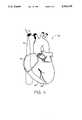
- FIG. 4is a prospective view of the human heart illustrating a guide wire which has been fed along a predetermined path into the right ventricle of the heart in implementing a first embodiment of the present invention
- FIG. 5is a prospective view of the human heart illustrating a lead being guided along the guide wire by an integrally formed follower in accordance with the first embodiment of the present invention
- FIG. 6is a prospective view of the human heart illustrating the lead at its final position with a distal electrode at an implantation site within the right ventricle of the heart and a proximal electrode at an implantation site within the right atrium of the heart in accordance with the first embodiment of the present invention
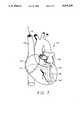
- FIG. 7is a prospective view of the human heart illustrating a guide wire which has been fed along a predetermined path into a coronary vein, such as the great vein, communicating with the coronary sinus of the heart to implement a second embodiment of the present invention
- FIG. 8is a prospective view of the human heart illustrating an intravenous lead being guided along the guide wire by an integrally formed follower in accordance with the second embodiment of the present invention.
- FIG. 9is a prospective view of the human heart illustrating the intravenous lead at its final position with a distal electrode at an implantation site within the great vein and a proximal electrode at an implantation site within the coronary sinus of the heart.
- FIG. 1it illustrates an arrangement 10 embodying the present invention to facilitate the implantation of an electrode of an endocardial or intravenous lead at an implantation site within or near the heart of the human body.
- the arrangement 10generally includes a guide wire 12 and a lead means 14.
- the lead means 14includes a proximal end 16, a distal end 18, and the electrode 20 to be implanted.
- the electrode 20is formed of conductive material so that, when implanted, the electrode 20 may be utilized for sensing heart activity or delivering electrical energy to the heart.
- the lead means 14further includes an outer insulative sleeve 22 and a Plurality of conductive wires 24 for connecting electrode 20 and other electrodes which Might be carried by lead 14 to a connector (not shown) disposed at the proximal end 16 of the lead 14.
- the electrode 20is disposed at the distal end 18 of the lead 14.
- the electrode 20, and hence the lead 14,includes an integrally formed follower 26 which includes an elongated channel 28.
- the elongated channel 28is substantially circular in cross-section and has an inner transverse dimension which is slightly greater in dimension than the outer transverse dimension of the guide wire 12.
- the follower 26is arranged for slidingly engaging the guide wire 12.
- the guide wire 12is preferably formed of flexible material so that, as will be seen hereinafter, it may be fed along a predetermined path within the body, which predetermined path includes the implantation site for the electrode 20.
- the follower 26is engaged with the guide wire 12 to permit the lead 14 to be guided along the predetermined path on the guide wire until the electrode 20 reaches the implantation site for the electrode.
- the guide wire 12may be retracted along the predetermined path causing the electrode 20 to remain and be implanted at the implantation site for electrode 20.
- FIGS. 4 through 6illustrate the manner in which the arrangement 10 may be utilized to advantage when the lead 14 is utilized as an endocardial lead and the electrode 20 is to be implanted within a chamber of the heart.
- the electrode 20is to be implanted within the right ventricle of the heart.
- FIG. 4it illustrates a human heart 30 in perspective view.
- the portions of the heart 30 of particular interest with respect to this first embodimentare the superior vena cava 32, the right atrium 34, and the right ventricle 36.
- the guide wire 12has been fed along a predetermined path including the superior vena cava 32, the right atrium 34, and the right ventricle 36.
- the guide wire 12has been fed along this predetermined path until the distal end 38 of guide wire 12 reaches the apex of the right ventricle 36 whereat the electrode 20 is to be implanted.
- FIG. 5it illustrates the lead 14 at an intermediate position as it is guided along the guide wire 12 by the follower integrally formed within the electrode 20.
- the follower 26(FIGS. 1 through 3) has been slidingly engaged on the guide wire 12 so that as the lead 14 is inserted into the heart 30, the lead 14 is guided along the predetermined path on the guide wire 12 through the superior vena cava 32 and into the right atrium 34.
- the lead 14carries another or proximal electrode 40.
- the proximal electrode 40is elongated and, as will be seen in FIG. 6, the proximal electrode 40 is spaced from the distal electrode 20 so that, when the electrode 20 resides at the apex of the right ventricle 36, the proximal electrode 40 will reside within the right atrium 34 of the heart 30.
- the lead 14has been guided along the guide wire 12 so that electrode 20 has reached the distal end 38 of the guide wire 12 and thus resides at its implantation site within the right ventricle 36 at the apex of the right ventricle 36. Also, the proximal electrode 40 resides at its implantation site within the right atrium 34 of the heart 30.
- the guide wire 20may now be retracted from the elongated channel of the integrally formed follower 26 and removed from the heart 30 along the predetermined path of the right ventricle 36, the right atrium 34, and the superior vena cava 32.
- the lead 14may find particular application with an implantable atrial defibrillator.
- the electrode 20is utilized for sensing heart activity within the right ventricle 36 of the heart 30 and the proximal electrode 40 may be utilized for sensing heart activity within the right atrium 34 of the heart 30 and as one of a pair of electrodes for delivering cardioverting electrical energy to the atria of the heart 30.
- FIGS. 7 through 9illustrate the manner in which the arrangement 10 of the present invention may be utilized to advantage when the lead 14 is to be utilized as an intravenous lead and the electrode 20 (herein referred to as electrode 20a in this second embodiment) is to be implanted within a coronary vein such as the great vein of the heart.
- a coronary veinsuch as the great vein of the heart.
- FIG. 7it again illustrates, in perspective view, the heart 30.
- the portions of the heart illustrated in FIG. 7 which are of particular interest in accordance with this second embodimentare the superior vena cava 32, the right atrium 34, the valve of coronary sinus 42, the coronary sinus 44, the great vein 46, the left atrium 48, and the left ventricle 50, of the heart 30.
- FIG. 7illustrates the manner in which the arrangement 10 of the present invention may be utilized to advantage when the lead 14 is to be utilized as an intravenous lead and the electrode 20 (herein referred to as electrode 20a in this second embodiment) is to be implanted within a
- the guide wire 12has been fed along a predetermined path within the heart including the superior vena cava 32, the right atrium 34, the valve of coronary sinus 42, the coronary sinus 44, and the great vein 46.
- the guide wire 12has been so fed along the aforementioned predetermined path so that the distal end 38 of the guide wire 12 is well within the great vein 46.
- FIG. 8it illustrates the lead 14 at an intermediate stage as it is being fed into the heart and guided along the aforementioned predetermined path on the guide wire 12.
- the integrally formed followerhas been slidingly engaged with the guide wire 12 so that the lead 14 may be guided along the predetermined path on the guide wire 12.
- the lead 14includes another or proximal electrode 40a.
- the electrode 40ais elongated in configuration and spaced from the distal electrode 20a such that when the distal electrode 20a reaches the distal end 38 of guide wire 12, well within the great vein 46, the proximal electrode 40a will reside in the coronary sinus 44 of the heart 30.
- the intermediate stage of the feeding of lead 14 along guide wire 12is such that the distal electrode 20a has just passed through the valve of coronary sinus 42 and has entered the coronary sinus 44.
- the lead 14has been guided along the guide wire 12 so that the distal electrode 20a has reached the distal end 38 of the guide wire 12.
- the distal electrode 20aresides at its implantation site well within the coronary sinus 46 and the proximal electrode 40a resides at its implantation site within the coronary sinus 44.
- the lead 14has been fed along the predetermined path including the superior vena cava 32, the right atrium 34, the valve of coronary sinus 42, the coronary sinus 44, and into the great vein 46.
- the guide wire 12may be retracted from the integrally formed follower and removed from the heart 30 in a reverse direction along the aforementioned predetermined path. This will cause the distal electrode 20a to remain at its implantation site within the great vein 46 and the proximal electrode 40a to remain at its implantation site within the coronary sinus 44. Because the coronary sinus 44 is closely adjacent to the left atrium 48 of the heart 30 and because the great vein 46 closely adjacent the left ventricle 50 of the heart 30, the lead 14 illustrated in FIG. 9 may be utilized to particular advantage with an implantable atrial defibrillator.
- the distal electrode 20a within the great vein 46may be utilized for sensing heart activity of the left ventricle 50 of the heart 30 and the proximal electrode 40a may be utilized for sensing heart activity of the left atrium 48 and as the second electrode of a pair of electrodes for delivering cardioverting electrical energy to the atria 34 and 48 of the heart 30.
- the proximal electrode 40 of FIG. 6 and the proximal electrode 40a of FIG. 9may be utilized for delivering cardioverting electrical energy to the atria 34 and 48 of the heart.
- the cardioverting electrical energyis delivered between the right atrium 34 and the coronary sinus 44 closely adjacent the left atrium 48.
- This delivery pathconcentrates the cardioverting electrical energy to the atria 34 and 48 of the heart.
- the proximal electrode 40 of FIG. 6 and the proximal electrode 40a of FIG. 9may also be utilized for sensing atrial activity of the heart to enable the determination as to whether atrial fibrillation is present within the heart.
- the arrangement disclosed herein in accordance with the present invention to facilitate the implantation of an electrode of an endocardial or intravenous lead at an implantation site within the heart of a humanexhibits a number of distinct advantages over the prior art.
- the followerwhich slidingly engages the guide wire 12 to permit the guiding of the lead along the predetermined path defined by the path of the guide wire, is integrally formed with the lead, the arrangement of the present invention requires fewer manipulations by the physician during implantation and thus minimizes added complexity to the already complex procedure of implanting such leads and electrodes.
- the integrally formed followerdoes not require a separate carriage for guiding the lead along the guide wire.
- the integrally formed followerdoes not require the bending of the lead to permit retraction of the guide wire. Since the guide wire is simply slidingly engaged within the elongated channel of the integrally formed follower, it need only be pulled in a reverse direction along the predetermined path for retraction. Still further, such ready retraction of the guide wire permits the electrodes to be in their final implantation positions when the guide wire is retracted thus negating the need to further position the electrodes after retraction of the guide wire. Lastly, since the follower may be integrally formed within the distal electrode, the follower itself serves a secondary function by being an integral part of the distal electrode for either sensing heart activity or delivering electrical energy to the heart.
Landscapes
- Health & Medical Sciences (AREA)
- Heart & Thoracic Surgery (AREA)
- Vascular Medicine (AREA)
- Cardiology (AREA)
- Engineering & Computer Science (AREA)
- Biomedical Technology (AREA)
- Nuclear Medicine, Radiotherapy & Molecular Imaging (AREA)
- Radiology & Medical Imaging (AREA)
- Life Sciences & Earth Sciences (AREA)
- Animal Behavior & Ethology (AREA)
- General Health & Medical Sciences (AREA)
- Public Health (AREA)
- Veterinary Medicine (AREA)
- Electrotherapy Devices (AREA)
Abstract
Description
The present invention relates to an arrangement to facilitate the implantation of an electrode at an implantation site within the human body. The present invention is more particularly directed to such an arrangement for implanting an electrode of a cardiac lead within a coronary vein of the human heart.
The practice of implanting cardiac pacemakers or defibrillators in the body of a human patient generally includes the implantation of one or more electrodes in, on, or near the heart. Such electrodes are used to either sense heart activity or deliver pacing or cardioverting electrical energy to the heart. Often, an electrode may be utilized for both functions.
Pacemakers and defibrillators generally include electrical components including sense amplifiers, a pulse generator, and a battery which are housed within a sealed enclosure. The enclosures are generally implanted in a subcutaneous pocket usually located in the subclavicular region in adults or in the abdominal region in children.
The pacemakers or defibrillators are generally coupled to the heart through one or more leads which include the aforementioned electrodes. The leads include a proximal end having a connector which connects to a terminal of the pacer or defibrillator enclosure and a distal end which carries the electrode. Some leads may include more than one electrode. The body of a lead is generally composed of conductive wires surrounded by insulation. The conductive wires couple the lead connector to the lead electrode or electrodes.
An endocardial lead is a lead which is implanted within a chamber of the heart so that the distal electrode of the lead can be fixed to the inner wall of a heart chamber. In implanting such a lead, a transvenous approach is utilized wherein the lead is inserted into and passed through the subclavian, jugular, or cephalic vein and into the appropriate heart chamber. An intravenous lead is a lead which is implanted within a coronary vein such as the great vein. As disclosed in copending application Ser. No. 07/856,514, filed on Mar. 24, 1992, in the names of John M. Adams, Clifton A. Alferness, and Paul E. Kreyenhagen, and entitled IMPROVED ATRIAL DEFIBRILLATOR, LEAD SYSTEMS, AND METHOD, which application is assigned to the assignee of the present invention and incorporated herein by reference, such an intravenous lead is particularly useful in an implantable atrial defibrillator application. The distal end of the intravenous lead there disclosed is passed through the superior vena cava, the right atrium, the valve of the coronary sinus, the coronary sinus, and into a coronary vein communicating with the coronary sinus, such as the great vein. The intravenous lead includes a distal or tip electrode which, when residing in the aforementioned coronary vein, such as the great vein, is closely adjacent the left ventricle of the heart for sensing ventricular activity of the heart. The lead further includes an elongated proximal electrode which is spaced from the distal or tip electrode so that when the tip electrode is within the coronary vein, the proximal electrode resides in the coronary sinus above the left ventricle and closely adjacent the left atrium of the heart. The proximal electrode is utilized for both sensing atrial activity of the heart and delivering cardioverting electrical energy to the atria between the coronary sinus and another electrode within the right atrium which is carried by either the same aforementioned intravenous lead or by another lead.
Experience has shown that it is often difficult to feed an endocardial or intravenous lead along a desired predetermined path to implant the electrode or electrodes at a desired implantation site either in a chamber of the heart or in a desired vein near the heart. This is especially true for intravenous leads due to anomalies in vascular anatomy and the number of veins which may communicate with the desired feed path.
One arrangement in attempting to solve this problem is described in Osypka, U.S. Pat. No. 5,003,990. The arrangement there disclosed includes a guide wire which is fed along a desired path through an artery or vein and a carriage arranged to releasably receive the distal end of a lead or catheter and to be pushed along the guide wire for guiding the lead along the guide wire. When the lead or catheter reaches the desired position, the carriage must be removed from the lead or catheter and then retracted along the guide wire by the pulling of another wire attached to the carriage or by the retraction of the guide wire. Such retraction of the carriage presents the possibility of damage to an artery or vein by the carriage. In addition, releasing the carriage from the guide wire requires the lead or catheter to be bent in the area of the carriage presenting further possibilities of tissue damage during such carriage removal. Still further, once the lead or catheter is free of the carriage, its distal end will not be at its desired final implantation position. Still further, use of the carriage during both implantation of the lead or catheter and retraction of the carriage requires numerous manipulations by the physician which only adds further complexity to an already complex procedure.
The present invention therefore provides an improved arrangement to facilitate the implantation of an electrode of an endocardial or intravenous lead at an implantation site within the body of a human. The arrangement includes guide wire means formed of flexible material and arranged to be fed along a predetermined path within the body wherein the predetermined path includes the implantation site. The arrangement further includes lead means formed of flexible material and including a proximal end, a distal end, and the electrode to be implanted. The lead means further includes follower means integrally formed in the lead means for slidingly engaging the guide wire means. As a result, after the guide wire means is fed to extend along the predetermined path, the follower means is engaged with the guide wire means to permit the lead means to be guided along the predetermined path until the electrode to be implanted resides at the implantation site whereupon, the guide wire means is retracted along the predetermined path to cause the electrode to be implanted to remain at the implantation site.
The present invention further provides a method of implanting an electrode at an implantation site within the body of a human. The method includes the steps of providing a guide wire formed of flexible material, feeding the guide wire along a predetermined path within the body wherein the predetermined path includes the implantation site, and providing lead means formed of flexible material and including a proximal end, a distal end, the electrode to be implanted, and a follower integrally formed in the lead means for slidingly engaging the guide wire. The method further includes the steps of engaging the follower means with the guide wire and sliding the lead means on the guide wire along the predetermined path until the electrode reaches the implantation site, and thereafter, sliding the guide wire from engagement with the follower means and retracting the guide wire from the body along the predetermined path.
The present invention more particularly provides a method of implanting an electrode at an implantation site within a coronary vein communicating with the coronary sinus in the body of a human. The method includes the steps of providing a guide wire formed of flexible material, feeding the guide wire along a predetermined path within the body wherein the predetermined path includes the superior vena cava, the right atrium, the valve of coronary sinus, the coronary sinus, and the coronary vein communicating with the coronary sinus, and providing lead means formed of flexible material and including a proximal end, a distal end, the electrode to be implanted, and a follower integrally formed in the lead means for slidingly engaging the guide wire. The method further includes the steps of engaging the follower means with the guide wire and sliding the lead means on the guide wire along the predetermined path until the electrode reaches the implantation site and thereafter, sliding the guide wire from engagement with the follower means and retracting the guide wire from the body along the predetermined path.
The features of the present invention which are believed to be novel are set forth with particularity in the appended claims. The invention, together with further objects and advantages thereof, may best be understood by making reference to the following description taken in conjunction with the accompanying drawings, in the several figures of which like reference numerals identify identical elements, and wherein:
FIG. 1 is a side plan view of an arrangement to facilitate the implantation of an electrode of an endocardial or intravenous lead at an implantation site within the human heart including a guide wire and a lead having an integrally formed follower slidingly engaged with the guide wire in accordance with the present invention;
FIG. 2 is a side view similar to FIG. 1, with the guide wire removed, and illustrating the follower in cross-section;
FIG. 3 is a side view similar to FIG. 1 illustrating the follower in cross-section and slidingly engaged with the guide wire;
FIG. 4 is a prospective view of the human heart illustrating a guide wire which has been fed along a predetermined path into the right ventricle of the heart in implementing a first embodiment of the present invention;
FIG. 5 is a prospective view of the human heart illustrating a lead being guided along the guide wire by an integrally formed follower in accordance with the first embodiment of the present invention;
FIG. 6 is a prospective view of the human heart illustrating the lead at its final position with a distal electrode at an implantation site within the right ventricle of the heart and a proximal electrode at an implantation site within the right atrium of the heart in accordance with the first embodiment of the present invention;
FIG. 7 is a prospective view of the human heart illustrating a guide wire which has been fed along a predetermined path into a coronary vein, such as the great vein, communicating with the coronary sinus of the heart to implement a second embodiment of the present invention;
FIG. 8 is a prospective view of the human heart illustrating an intravenous lead being guided along the guide wire by an integrally formed follower in accordance with the second embodiment of the present invention; and
FIG. 9 is a prospective view of the human heart illustrating the intravenous lead at its final position with a distal electrode at an implantation site within the great vein and a proximal electrode at an implantation site within the coronary sinus of the heart.
Referring now to FIG. 1, it illustrates anarrangement 10 embodying the present invention to facilitate the implantation of an electrode of an endocardial or intravenous lead at an implantation site within or near the heart of the human body. Thearrangement 10 generally includes aguide wire 12 and a lead means 14. The lead means 14 includes aproximal end 16, adistal end 18, and theelectrode 20 to be implanted. Theelectrode 20 is formed of conductive material so that, when implanted, theelectrode 20 may be utilized for sensing heart activity or delivering electrical energy to the heart.
In a manner well known in the art, the lead means 14 further includes an outerinsulative sleeve 22 and a Plurality ofconductive wires 24 for connectingelectrode 20 and other electrodes which Might be carried bylead 14 to a connector (not shown) disposed at theproximal end 16 of thelead 14.
As may best be seen in FIG. 2, theelectrode 20 is disposed at thedistal end 18 of thelead 14. Theelectrode 20, and hence thelead 14, includes an integrally formedfollower 26 which includes anelongated channel 28. Theelongated channel 28 is substantially circular in cross-section and has an inner transverse dimension which is slightly greater in dimension than the outer transverse dimension of theguide wire 12. As a result, and as can best be seen in FIG. 3, because theelongated channel 28 has an inner transverse dimension slightly greater in dimension than the outer transverse dimension of theguide wire 12, thefollower 26 is arranged for slidingly engaging theguide wire 12.
Theguide wire 12 is preferably formed of flexible material so that, as will be seen hereinafter, it may be fed along a predetermined path within the body, which predetermined path includes the implantation site for theelectrode 20. As will further be seen hereinafter, after theguide wire 12 is fed to extend along the predetermined path, thefollower 26 is engaged with theguide wire 12 to permit thelead 14 to be guided along the predetermined path on the guide wire until theelectrode 20 reaches the implantation site for the electrode. When theelectrode 20 reaches the implantation site, theguide wire 12 may be retracted along the predetermined path causing theelectrode 20 to remain and be implanted at the implantation site forelectrode 20.
FIGS. 4 through 6 illustrate the manner in which thearrangement 10 may be utilized to advantage when thelead 14 is utilized as an endocardial lead and theelectrode 20 is to be implanted within a chamber of the heart. In accordance with this first embodiment, theelectrode 20 is to be implanted within the right ventricle of the heart.
Referring to FIG. 4, it illustrates ahuman heart 30 in perspective view. The portions of theheart 30 of particular interest with respect to this first embodiment are thesuperior vena cava 32, theright atrium 34, and theright ventricle 36. Theguide wire 12 has been fed along a predetermined path including thesuperior vena cava 32, theright atrium 34, and theright ventricle 36. Theguide wire 12 has been fed along this predetermined path until thedistal end 38 ofguide wire 12 reaches the apex of theright ventricle 36 whereat theelectrode 20 is to be implanted.
Referring now to FIG. 5, it illustrates thelead 14 at an intermediate position as it is guided along theguide wire 12 by the follower integrally formed within theelectrode 20. To that end, the follower 26 (FIGS. 1 through 3) has been slidingly engaged on theguide wire 12 so that as thelead 14 is inserted into theheart 30, thelead 14 is guided along the predetermined path on theguide wire 12 through thesuperior vena cava 32 and into theright atrium 34.
As will also be noted in FIG. 5, the lead 14 carries another orproximal electrode 40. Theproximal electrode 40 is elongated and, as will be seen in FIG. 6, theproximal electrode 40 is spaced from thedistal electrode 20 so that, when theelectrode 20 resides at the apex of theright ventricle 36, theproximal electrode 40 will reside within theright atrium 34 of theheart 30.
Referring now to FIG. 6, it can be seen that thelead 14 has been guided along theguide wire 12 so thatelectrode 20 has reached thedistal end 38 of theguide wire 12 and thus resides at its implantation site within theright ventricle 36 at the apex of theright ventricle 36. Also, theproximal electrode 40 resides at its implantation site within theright atrium 34 of theheart 30. Withelectrode 20 residing at its implantation site within theright ventricle 36 and with theproximal electrode 40 residing at its implantation site within theright atrium 34, theguide wire 20 may now be retracted from the elongated channel of the integrally formedfollower 26 and removed from theheart 30 along the predetermined path of theright ventricle 36, theright atrium 34, and thesuperior vena cava 32.
Thelead 14 may find particular application with an implantable atrial defibrillator. In such an application, theelectrode 20 is utilized for sensing heart activity within theright ventricle 36 of theheart 30 and theproximal electrode 40 may be utilized for sensing heart activity within theright atrium 34 of theheart 30 and as one of a pair of electrodes for delivering cardioverting electrical energy to the atria of theheart 30.
FIGS. 7 through 9 illustrate the manner in which thearrangement 10 of the present invention may be utilized to advantage when thelead 14 is to be utilized as an intravenous lead and the electrode 20 (herein referred to aselectrode 20a in this second embodiment) is to be implanted within a coronary vein such as the great vein of the heart. Referring more particularly to FIG. 7, it again illustrates, in perspective view, theheart 30. The portions of the heart illustrated in FIG. 7 which are of particular interest in accordance with this second embodiment are thesuperior vena cava 32, theright atrium 34, the valve ofcoronary sinus 42, thecoronary sinus 44, thegreat vein 46, theleft atrium 48, and theleft ventricle 50, of theheart 30. As will be noted in FIG. 7, theguide wire 12 has been fed along a predetermined path within the heart including thesuperior vena cava 32, theright atrium 34, the valve ofcoronary sinus 42, thecoronary sinus 44, and thegreat vein 46. Theguide wire 12 has been so fed along the aforementioned predetermined path so that thedistal end 38 of theguide wire 12 is well within thegreat vein 46.
Referring now to FIG. 8, it illustrates thelead 14 at an intermediate stage as it is being fed into the heart and guided along the aforementioned predetermined path on theguide wire 12. To that end, the integrally formed follower has been slidingly engaged with theguide wire 12 so that thelead 14 may be guided along the predetermined path on theguide wire 12. As will also be noted in FIG. 8, thelead 14 includes another or proximal electrode 40a. The electrode 40a is elongated in configuration and spaced from thedistal electrode 20a such that when thedistal electrode 20a reaches thedistal end 38 ofguide wire 12, well within thegreat vein 46, the proximal electrode 40a will reside in thecoronary sinus 44 of theheart 30. As illustrated in FIG. 8, the intermediate stage of the feeding oflead 14 alongguide wire 12 is such that thedistal electrode 20a has just passed through the valve ofcoronary sinus 42 and has entered thecoronary sinus 44.
Referring now to FIG. 9, it may be seen that thelead 14 has been guided along theguide wire 12 so that thedistal electrode 20a has reached thedistal end 38 of theguide wire 12. As a result, thedistal electrode 20a resides at its implantation site well within thecoronary sinus 46 and the proximal electrode 40a resides at its implantation site within thecoronary sinus 44. As a result, thelead 14 has been fed along the predetermined path including thesuperior vena cava 32, theright atrium 34, the valve ofcoronary sinus 42, thecoronary sinus 44, and into thegreat vein 46.
With thedistal electrode 20a residing at its implantation site within thegreat vein 46 and with the proximal electrode 40a residing at its implantation site within thecoronary sinus 44, theguide wire 12 may be retracted from the integrally formed follower and removed from theheart 30 in a reverse direction along the aforementioned predetermined path. This will cause thedistal electrode 20a to remain at its implantation site within thegreat vein 46 and the proximal electrode 40a to remain at its implantation site within thecoronary sinus 44. Because thecoronary sinus 44 is closely adjacent to theleft atrium 48 of theheart 30 and because thegreat vein 46 closely adjacent theleft ventricle 50 of theheart 30, thelead 14 illustrated in FIG. 9 may be utilized to particular advantage with an implantable atrial defibrillator. In such an application, thedistal electrode 20a within thegreat vein 46 may be utilized for sensing heart activity of theleft ventricle 50 of theheart 30 and the proximal electrode 40a may be utilized for sensing heart activity of theleft atrium 48 and as the second electrode of a pair of electrodes for delivering cardioverting electrical energy to theatria heart 30. More specifically, and as disclosed in the aforementioned copending application Ser. No. 07/856,514, theproximal electrode 40 of FIG. 6 and the proximal electrode 40a of FIG. 9 may be utilized for delivering cardioverting electrical energy to theatria right atrium 34 and thecoronary sinus 44 closely adjacent theleft atrium 48. This delivery path concentrates the cardioverting electrical energy to theatria proximal electrode 40 of FIG. 6 and the proximal electrode 40a of FIG. 9 may also be utilized for sensing atrial activity of the heart to enable the determination as to whether atrial fibrillation is present within the heart. Thedistal electrode 20 of FIG. 6 and thedistal electrode 20a of FIG. 9 may be utilized for sensing ventricular activity of the heart to enable a determination as to whether atrial fibrillation may be occurring and to enable the cardioverting electrical energy to be applied to theatria ventricles distal electrode 20 of FIG. 6 and thedistal electrode 20a of FIG. 9.
The arrangement disclosed herein in accordance with the present invention to facilitate the implantation of an electrode of an endocardial or intravenous lead at an implantation site within the heart of a human exhibits a number of distinct advantages over the prior art. For example, since the follower, which slidingly engages theguide wire 12 to permit the guiding of the lead along the predetermined path defined by the path of the guide wire, is integrally formed with the lead, the arrangement of the present invention requires fewer manipulations by the physician during implantation and thus minimizes added complexity to the already complex procedure of implanting such leads and electrodes. In addition, the integrally formed follower does not require a separate carriage for guiding the lead along the guide wire. As a result, there is no need for retracting such a carriage from the heart once the lead and electrode or electrodes are implanted. In addition, the integrally formed follower does not require the bending of the lead to permit retraction of the guide wire. Since the guide wire is simply slidingly engaged within the elongated channel of the integrally formed follower, it need only be pulled in a reverse direction along the predetermined path for retraction. Still further, such ready retraction of the guide wire permits the electrodes to be in their final implantation positions when the guide wire is retracted thus negating the need to further position the electrodes after retraction of the guide wire. Lastly, since the follower may be integrally formed within the distal electrode, the follower itself serves a secondary function by being an integral part of the distal electrode for either sensing heart activity or delivering electrical energy to the heart.
While particular embodiments of the present invention have been shown and described, modifications may be made, and it is therefore intended to cover in the appended claims, all such changes and modifications which fall within the true spirit and scope of the invention.
Claims (12)
1. An arrangement to facilitate the implantation of an electrode of an endocardial or intravenous lead at an implantation site within a human body, said arrangement comprising:
a guide wire formed of flexible material and arranged to be fed along a predetermined path within the body, said predetermined path including said implantation site; and
a lead formed of flexible material, said lead including a proximal end, a distal end, and an electrode to be implanted, said electrode to be implanted including follower means for slidingly engaging said guide wire whereby,
after said guide wire is fed to extend along said predetermined path, said follower means is engaged with said guide wire to permit said lead to be guided along said predetermined path until said electrode to be implanted resides at said implantation site whereupon, said guide wire is retracted from said follower means and along said predetermined path to cause said electrode to be implanted to remain at said implantation site.
2. An arrangement as defined in claim 1 wherein said guide wire has an outer transverse dimension and wherein said follower means includes an elongated channel having an inner transverse dimension slightly greater in dimension than said outer transverse dimension of said guide wire.
3. An arrangement as defined in claim 1 wherein said electrode to be implanted is at said distal end of said lead.
4. An arrangement as defined in claim 3 wherein said guide wire has an outer transverse dimension and wherein said follower means includes an elongated channel having an inner transverse dimension slightly greater in dimension than said outer transverse dimension of said guide wire.
5. A method of implanting an electrode at an implantation site within a human body, said method comprising the steps of:
providing a guide wire formed of flexible material;
feeding said guide wire along a predetermined path within the body, said predetermined path including said implantation site;
providing a lead formed of flexible material and including a proximal end, a distal end, an electrode to be implanted, and a follower integrally formed in said lead, said follower for slidingly engaging said guide wire;
engaging said follower with said guide wire and sliding said lead on said guide wire along said predetermined path until said electrode to be implanted reaches said implantation site; and thereafter
sliding said guide wire from engagement with said follower and retracting said guide wire from the body along said predetermined path.
6. A method as defined in claim 5 wherein said electrode to be implanted is at the distal end of said lead.
7. A method of implanting an electrode at an implantation site within a coronary vein of a human body having a coronary sinus communicating with the coronary vein, a superior vena cava, a right atrium, and a valve of coronary sinus, said method comprising the steps of:
providing a guide wire formed of flexible material;
feeding said guide wire along a predetermined path within the body, said predetermined path including the superior vena cava, the right atrium, the valve of coronary sinus, the coronary sinus, and said coronary vein communicating with the coronary sinus;
providing a lead formed of flexible material and including a proximal end, a distal end, an electrode to be implanted, and a follower integrally formed in said lead, said follower for slidingly engaging said guide wire;
engaging said follower with said guide wire and sliding said lead on said guide wire along said predetermined path until said electrode to be implanted reaches said implantation site; and thereafter
sliding said guide wire from engagement with said follower and retracting said guide wire from the body along said predetermined path.
8. A method as defined in claim 7 wherein said electrode to be implanted is at the distal end of said lead.
9. An arrangement to facilitate the implantation of an electrode at an endocardial or intravenous lead at an implantation site within a human body, said arrangement comprising:
a guide wire formed of flexible material and arranged to be fed along a predetermined path within the body, said predetermined path including said implantation site; and
a lead formed of flexible material, said lead including a proximal end, a distal end, and an electrode to be implanted, said lead further including follower means formed on said lead so as to be non-removable from said lead, said follower means for slidingly engaging said guide wire whereby,
after said guide wire is fed to extend along said predetermined path, said follower means is engaged with said guide wire to permit said lead to be guided along said predetermined path until said electrode to be implanted resides at said implantation site whereupon, said guide wire is retracted from said follower means and along said predetermined path to cause said electrode to be implanted to remain at said implantation site.
10. An arrangement as defined in claim 9 wherein said lead includes said electrode to be implanted at said distal end of said lead.
11. An arrangement as defined in claim 10 wherein said electrode to be implanted includes said follower means.
12. An arrangement as defined in claim 11 wherein said guide wire has an outer transverse dimension and wherein said follower means includes an elongated channel having an inner transverse dimension slightly greater in dimension than said outer transverse dimension of said guide wire.
Priority Applications (1)
| Application Number | Priority Date | Filing Date | Title |
|---|---|---|---|
| US07/892,177US5304218A (en) | 1992-06-02 | 1992-06-02 | Cardiac lead implanting arrangement and method |
Applications Claiming Priority (1)
| Application Number | Priority Date | Filing Date | Title |
|---|---|---|---|
| US07/892,177US5304218A (en) | 1992-06-02 | 1992-06-02 | Cardiac lead implanting arrangement and method |
Publications (1)
| Publication Number | Publication Date |
|---|---|
| US5304218Atrue US5304218A (en) | 1994-04-19 |
Family
ID=25399501
Family Applications (1)
| Application Number | Title | Priority Date | Filing Date |
|---|---|---|---|
| US07/892,177Expired - Fee RelatedUS5304218A (en) | 1992-06-02 | 1992-06-02 | Cardiac lead implanting arrangement and method |
Country Status (1)
| Country | Link |
|---|---|
| US (1) | US5304218A (en) |
Cited By (45)
| Publication number | Priority date | Publication date | Assignee | Title |
|---|---|---|---|---|
| US5755765A (en)* | 1997-01-24 | 1998-05-26 | Cardiac Pacemakers, Inc. | Pacing lead having detachable positioning member |
| WO1998032486A1 (en) | 1997-01-24 | 1998-07-30 | Cardiac Pacemakers, Inc. | Cardiac lead arrangement |
| WO1998032375A1 (en) | 1997-01-24 | 1998-07-30 | Cardiac Pacemakers, Inc. | Side access 'over the wire' pacing lead |
| US5800497A (en)* | 1997-07-17 | 1998-09-01 | Medtronic, Inc. | Medical electrical lead with temporarily stiff portion |
| US5902331A (en)* | 1998-03-10 | 1999-05-11 | Medtronic, Inc. | Arrangement for implanting an endocardial cardiac lead |
| US5987354A (en)* | 1996-08-13 | 1999-11-16 | Uab Research Foundation | Dual shock atrial defibrillation apparatus |
| US6006131A (en)* | 1996-08-13 | 1999-12-21 | Uab Research Foundation | Dual current pathway atrial defibrillation apparatus |
| WO2000010639A1 (en)* | 1998-08-25 | 2000-03-02 | Cardiac Pacemakers, Inc. | Monorail left ventricular access lead |
| EP1013304A2 (en) | 1998-12-18 | 2000-06-28 | Pacesetter AB | A device for guiding and positioning leads |
| US6094596A (en)* | 1998-06-19 | 2000-07-25 | Angeron Corporation | Transvenous defibrillation lead system for use in middle cardiac vein |
| US6132456A (en)* | 1998-03-10 | 2000-10-17 | Medtronic, Inc. | Arrangement for implanting an endocardial cardiac lead |
| WO2000072911A1 (en) | 1999-06-02 | 2000-12-07 | Medtronic, Inc. | Guidewire placed implantable lead with tip seal |
| US6484057B2 (en) | 2000-12-21 | 2002-11-19 | Uab Research Foundation | Pacing methods and devices for treating cardiac arrhythmias and fibrillation |
| US6493591B1 (en)* | 2000-07-19 | 2002-12-10 | Medtronic, Inc. | Implantable active fixation lead with guidewire tip |
| US6574512B1 (en) | 2000-08-28 | 2003-06-03 | Cardiac Pacemakers, Inc. | Lead system with main lead and transverse lead |
| US20030105506A1 (en)* | 2001-12-04 | 2003-06-05 | Cardiac Pacemakers, Inc. | Apparatus and method for stabilizing an implantable lead |
| US6671560B2 (en) | 1998-06-12 | 2003-12-30 | Cardiac Pacemakers, Inc. | Modified guidewire for left ventricular access lead |
| US20040024421A1 (en)* | 2002-07-31 | 2004-02-05 | Ideker Raymond E. | Pacing methods and devices using feedback controlled timing |
| US20040049232A1 (en)* | 2002-09-10 | 2004-03-11 | Ideker Raymond E. | Post-defibrillation pacing methods and devices |
| US20040049117A1 (en)* | 2002-09-10 | 2004-03-11 | Ideker Raymond E. | Devices for detecting the presence of cardiac activity following administration of defibrillation therapy |
| US20040049118A1 (en)* | 2002-09-10 | 2004-03-11 | Ideker Raymond E. | Methods, systems and computer program products for treating fibrillation in a patient based on the presence of fibrillation following administration of defibrillation therapy |
| US20040172116A1 (en)* | 2003-01-31 | 2004-09-02 | Medtronic, Inc. | Arrangement for implanting a miniaturized cardiac lead having a fixation helix |
| US20040199211A1 (en)* | 1997-04-04 | 2004-10-07 | Cardiac Pacemakers, Inc. | Methods and systems for promoting ventricular pacing |
| US6817364B2 (en) | 2000-07-24 | 2004-11-16 | Stereotaxis, Inc. | Magnetically navigated pacing leads, and methods for delivering medical devices |
| US20050085885A1 (en)* | 1998-08-12 | 2005-04-21 | Cardiac Pacemakers, Inc. | Expandable seal for use with medical device and system |
| US6934589B2 (en) | 2000-12-29 | 2005-08-23 | Medtronic, Inc. | System and method for placing endocardial leads |
| EP1428546A3 (en)* | 2002-12-11 | 2005-10-19 | Cryocor, Inc. | Guidance system for a cryocatheter |
| US20060036307A1 (en)* | 2004-08-16 | 2006-02-16 | Cardiac Pacemakers, Inc. | Lead assembly and methods including a push tube |
| US20060079949A1 (en)* | 2004-10-12 | 2006-04-13 | Medtronic, Inc. | Lead stabilizer and extension wire |
| US20060155334A1 (en)* | 2003-03-13 | 2006-07-13 | Ideker Raymond E | Methods and systems for reducing discomfort from cardiac defibrillation shocks |
| US20060247751A1 (en)* | 2005-04-28 | 2006-11-02 | Seifert Kevin R | Guide catheters for accessing cardiac sites |
| US20070123965A1 (en)* | 2003-01-29 | 2007-05-31 | Cardiac Pacemakers, Inc. | Medical electrical lead employing load bearing sleeve |
| US20080243195A1 (en)* | 2007-03-30 | 2008-10-02 | Sommer John L | Mapping guidelet |
| US20080243215A1 (en)* | 2007-03-30 | 2008-10-02 | Sommer John L | Controller for a medical lead delivery device |
| US20090076521A1 (en)* | 2007-09-18 | 2009-03-19 | Morten Hansen | Apparatus and method for inserting implants into the body |
| WO2009073754A2 (en) | 2007-12-03 | 2009-06-11 | Innerpulse | Implantation methods, systems and tools for intravascular implantable devices |
| US20090182403A1 (en)* | 2008-01-10 | 2009-07-16 | Arkady Glukhovsky | Methods and apparatus for implanting electronic implants within the body |
| US7657324B2 (en) | 1998-08-12 | 2010-02-02 | Cardiac Pacemakers, Inc. | Seal for use with cardiac lead |
| US20100036465A1 (en)* | 2008-08-07 | 2010-02-11 | Arkady Glukhovsky | Insertion tools and methods for an electrical stimulation implant |
| US7734344B2 (en) | 2003-12-02 | 2010-06-08 | Uab Research Foundation | Methods, systems and computer program products to inhibit ventricular fibrillation during cardiopulmonary resuscitation |
| US7881806B2 (en) | 2006-10-31 | 2011-02-01 | Medtronic, Inc. | Medical lead delivery device |
| US20110077725A1 (en)* | 2009-09-30 | 2011-03-31 | Medtronic, Inc. | Medical electrical lead |
| US8103358B2 (en) | 2003-04-04 | 2012-01-24 | Medtronic, Inc. | Mapping guidelet |
| US8509916B2 (en) | 2002-12-16 | 2013-08-13 | Medtronic, Inc. | Bilumen guide catheters for accessing cardiac sites |
| US8532733B2 (en) | 2006-10-31 | 2013-09-10 | Medtronic, Inc. | Mapping guidelet |
Citations (3)
| Publication number | Priority date | Publication date | Assignee | Title |
|---|---|---|---|---|
| US4972847A (en)* | 1989-11-02 | 1990-11-27 | Dutcher Robert G | Pacing lead and introducer therefor |
| US5003990A (en)* | 1988-07-28 | 1991-04-02 | Peter Osypka | Apparatus for implanting electrodes and the like in animal bodies |
| US5139033A (en)* | 1991-03-04 | 1992-08-18 | Cardiac Pacemakers, Inc. | Sutureless myocardial lead implantation device |
- 1992
- 1992-06-02USUS07/892,177patent/US5304218A/ennot_activeExpired - Fee Related
Patent Citations (3)
| Publication number | Priority date | Publication date | Assignee | Title |
|---|---|---|---|---|
| US5003990A (en)* | 1988-07-28 | 1991-04-02 | Peter Osypka | Apparatus for implanting electrodes and the like in animal bodies |
| US4972847A (en)* | 1989-11-02 | 1990-11-27 | Dutcher Robert G | Pacing lead and introducer therefor |
| US5139033A (en)* | 1991-03-04 | 1992-08-18 | Cardiac Pacemakers, Inc. | Sutureless myocardial lead implantation device |
Cited By (85)
| Publication number | Priority date | Publication date | Assignee | Title |
|---|---|---|---|---|
| US6327500B1 (en) | 1996-08-13 | 2001-12-04 | Uab Research Foundation | Dual shock atrial defibrillation apparatus |
| US5987354A (en)* | 1996-08-13 | 1999-11-16 | Uab Research Foundation | Dual shock atrial defibrillation apparatus |
| US6006131A (en)* | 1996-08-13 | 1999-12-21 | Uab Research Foundation | Dual current pathway atrial defibrillation apparatus |
| US5755765A (en)* | 1997-01-24 | 1998-05-26 | Cardiac Pacemakers, Inc. | Pacing lead having detachable positioning member |
| WO1998032485A1 (en)* | 1997-01-24 | 1998-07-30 | Cardiac Pacemakers, Inc. | Pacing lead having detachable positioning member |
| WO1998032486A1 (en) | 1997-01-24 | 1998-07-30 | Cardiac Pacemakers, Inc. | Cardiac lead arrangement |
| WO1998032375A1 (en) | 1997-01-24 | 1998-07-30 | Cardiac Pacemakers, Inc. | Side access 'over the wire' pacing lead |
| US5803928A (en)* | 1997-01-24 | 1998-09-08 | Cardiac Pacemakers, Inc. | Side access "over the wire" pacing lead |
| EP1902748A1 (en) | 1997-01-24 | 2008-03-26 | Cardiac Pacemakers, Inc. | Cardiac lead arrangement |
| US20070118179A1 (en)* | 1997-04-04 | 2007-05-24 | Cardiac Pacemakers, Inc. | Device and method for ventricular tracking and pacing |
| US7463925B2 (en) | 1997-04-04 | 2008-12-09 | Cardiac Pacemakers, Inc. | Methods and systems for promoting ventricular pacing |
| US8214034B2 (en) | 1997-04-04 | 2012-07-03 | Cardiac Pacemakers, Inc. | Device and method for ventricular tracking and pacing |
| US20040210266A1 (en)* | 1997-04-04 | 2004-10-21 | Cardiac Pacemakers, Inc. | Methods and systems for promoting ventricular pacing |
| US7483739B2 (en) | 1997-04-04 | 2009-01-27 | Cardiac Pacemakers, Inc. | Methods and systems for promoting ventricular pacing |
| US20040199211A1 (en)* | 1997-04-04 | 2004-10-07 | Cardiac Pacemakers, Inc. | Methods and systems for promoting ventricular pacing |
| US7471981B2 (en) | 1997-04-04 | 2008-12-30 | Cardiac Pacemakers, Inc. | Methods and systems for promoting ventricular pacing |
| US20040210265A1 (en)* | 1997-04-04 | 2004-10-21 | Cardiac Pacemakers, Inc., | Methods and systems for promoting ventricular pacing |
| US5800497A (en)* | 1997-07-17 | 1998-09-01 | Medtronic, Inc. | Medical electrical lead with temporarily stiff portion |
| US5902331A (en)* | 1998-03-10 | 1999-05-11 | Medtronic, Inc. | Arrangement for implanting an endocardial cardiac lead |
| US6868291B1 (en) | 1998-03-10 | 2005-03-15 | Medtronic, Inc. | Arrangement for implanting an endocardial cardiac lead |
| US6132456A (en)* | 1998-03-10 | 2000-10-17 | Medtronic, Inc. | Arrangement for implanting an endocardial cardiac lead |
| US6671560B2 (en) | 1998-06-12 | 2003-12-30 | Cardiac Pacemakers, Inc. | Modified guidewire for left ventricular access lead |
| US6094596A (en)* | 1998-06-19 | 2000-07-25 | Angeron Corporation | Transvenous defibrillation lead system for use in middle cardiac vein |
| US20050085885A1 (en)* | 1998-08-12 | 2005-04-21 | Cardiac Pacemakers, Inc. | Expandable seal for use with medical device and system |
| US7412290B2 (en) | 1998-08-12 | 2008-08-12 | Cardiac Pacemakers, Inc. | Seal for use with medical device and system |
| US6901288B2 (en) | 1998-08-12 | 2005-05-31 | Cardiac Pacemakers, Inc. | Sealing assembly for intravenous lead |
| US7657324B2 (en) | 1998-08-12 | 2010-02-02 | Cardiac Pacemakers, Inc. | Seal for use with cardiac lead |
| WO2000010639A1 (en)* | 1998-08-25 | 2000-03-02 | Cardiac Pacemakers, Inc. | Monorail left ventricular access lead |
| US6129749A (en)* | 1998-08-25 | 2000-10-10 | Cardiac Pacemakers, Inc. | Monorail left ventricular access lead |
| EP1013304A2 (en) | 1998-12-18 | 2000-06-28 | Pacesetter AB | A device for guiding and positioning leads |
| US6192280B1 (en) | 1999-06-02 | 2001-02-20 | Medtronic, Inc. | Guidewire placed implantable lead with tip seal |
| WO2000072911A1 (en) | 1999-06-02 | 2000-12-07 | Medtronic, Inc. | Guidewire placed implantable lead with tip seal |
| US6493591B1 (en)* | 2000-07-19 | 2002-12-10 | Medtronic, Inc. | Implantable active fixation lead with guidewire tip |
| US6817364B2 (en) | 2000-07-24 | 2004-11-16 | Stereotaxis, Inc. | Magnetically navigated pacing leads, and methods for delivering medical devices |
| US6574512B1 (en) | 2000-08-28 | 2003-06-03 | Cardiac Pacemakers, Inc. | Lead system with main lead and transverse lead |
| US6871101B2 (en) | 2000-08-28 | 2005-03-22 | Cardiac Pacemakers, Inc. | Lead system with sleeve for passing a lead |
| US6484057B2 (en) | 2000-12-21 | 2002-11-19 | Uab Research Foundation | Pacing methods and devices for treating cardiac arrhythmias and fibrillation |
| US6934589B2 (en) | 2000-12-29 | 2005-08-23 | Medtronic, Inc. | System and method for placing endocardial leads |
| US6961621B2 (en)* | 2001-12-04 | 2005-11-01 | Cardiac Pacemakers, Inc. | Apparatus and method for stabilizing an implantable lead |
| US20030105506A1 (en)* | 2001-12-04 | 2003-06-05 | Cardiac Pacemakers, Inc. | Apparatus and method for stabilizing an implantable lead |
| US7139608B2 (en) | 2002-07-31 | 2006-11-21 | Uab Research Foundation | Pacing methods and devices using feedback controlled timing |
| US20040024421A1 (en)* | 2002-07-31 | 2004-02-05 | Ideker Raymond E. | Pacing methods and devices using feedback controlled timing |
| US8560063B2 (en) | 2002-09-10 | 2013-10-15 | Uab Research Foundation | Post-defibrillation pacing methods and devices |
| US7162298B2 (en) | 2002-09-10 | 2007-01-09 | Uab Research Foundation | Devices for detecting the presence of cardiac activity following administration of defibrillation therapy |
| US20040049118A1 (en)* | 2002-09-10 | 2004-03-11 | Ideker Raymond E. | Methods, systems and computer program products for treating fibrillation in a patient based on the presence of fibrillation following administration of defibrillation therapy |
| US20040049117A1 (en)* | 2002-09-10 | 2004-03-11 | Ideker Raymond E. | Devices for detecting the presence of cardiac activity following administration of defibrillation therapy |
| US20040049232A1 (en)* | 2002-09-10 | 2004-03-11 | Ideker Raymond E. | Post-defibrillation pacing methods and devices |
| EP1428546A3 (en)* | 2002-12-11 | 2005-10-19 | Cryocor, Inc. | Guidance system for a cryocatheter |
| US8509916B2 (en) | 2002-12-16 | 2013-08-13 | Medtronic, Inc. | Bilumen guide catheters for accessing cardiac sites |
| US7738970B2 (en) | 2003-01-29 | 2010-06-15 | Cardiac Pacemakers, Inc. | Medical electrical lead employing load bearing sleeve |
| US20070123965A1 (en)* | 2003-01-29 | 2007-05-31 | Cardiac Pacemakers, Inc. | Medical electrical lead employing load bearing sleeve |
| US7158838B2 (en) | 2003-01-31 | 2007-01-02 | Medtronic, Inc. | Arrangement for implanting a miniaturized cardiac lead having a fixation helix |
| US20040172116A1 (en)* | 2003-01-31 | 2004-09-02 | Medtronic, Inc. | Arrangement for implanting a miniaturized cardiac lead having a fixation helix |
| US20060155334A1 (en)* | 2003-03-13 | 2006-07-13 | Ideker Raymond E | Methods and systems for reducing discomfort from cardiac defibrillation shocks |
| US7522958B2 (en) | 2003-03-13 | 2009-04-21 | Uab Research Foundation | Methods and systems for reducing discomfort from cardiac defibrillation shocks |
| US8103358B2 (en) | 2003-04-04 | 2012-01-24 | Medtronic, Inc. | Mapping guidelet |
| US20100204623A1 (en)* | 2003-12-02 | 2010-08-12 | Ideker Raymond E | Methods, Systems and Computer Program Products to Inhibit Ventricular Fibrillation During Cardiopulmonary Resuscitation |
| US7734344B2 (en) | 2003-12-02 | 2010-06-08 | Uab Research Foundation | Methods, systems and computer program products to inhibit ventricular fibrillation during cardiopulmonary resuscitation |
| US8843195B2 (en) | 2003-12-02 | 2014-09-23 | Uab Research Foundation | Methods, systems and computer program products to inhibit ventricular fibrillation during cardiopulmonary resuscitation |
| US20100228263A1 (en)* | 2004-08-16 | 2010-09-09 | Zarembo Paul E | Lead assembly and methods including a push tube |
| US8396569B2 (en) | 2004-08-16 | 2013-03-12 | Cardiac Pacemakers, Inc. | Lead assembly and methods including a push tube |
| US20060036307A1 (en)* | 2004-08-16 | 2006-02-16 | Cardiac Pacemakers, Inc. | Lead assembly and methods including a push tube |
| US7747333B2 (en)* | 2004-08-16 | 2010-06-29 | Cardiac Pacemakers, Inc. | Lead assembly and methods including a push tube |
| US20060079949A1 (en)* | 2004-10-12 | 2006-04-13 | Medtronic, Inc. | Lead stabilizer and extension wire |
| US7283878B2 (en) | 2004-10-12 | 2007-10-16 | Medtronic, Inc. | Lead stabilizer and extension wire |
| US20060247751A1 (en)* | 2005-04-28 | 2006-11-02 | Seifert Kevin R | Guide catheters for accessing cardiac sites |
| US7974710B2 (en) | 2005-04-28 | 2011-07-05 | Medtronic, Inc. | Guide catheters for accessing cardiac sites |
| US8532733B2 (en) | 2006-10-31 | 2013-09-10 | Medtronic, Inc. | Mapping guidelet |
| US7881806B2 (en) | 2006-10-31 | 2011-02-01 | Medtronic, Inc. | Medical lead delivery device |
| US20080243215A1 (en)* | 2007-03-30 | 2008-10-02 | Sommer John L | Controller for a medical lead delivery device |
| US8644955B2 (en) | 2007-03-30 | 2014-02-04 | Medtronic, Inc. | Controller for a medical lead delivery device |
| US20080243195A1 (en)* | 2007-03-30 | 2008-10-02 | Sommer John L | Mapping guidelet |
| US20090076521A1 (en)* | 2007-09-18 | 2009-03-19 | Morten Hansen | Apparatus and method for inserting implants into the body |
| US8057486B2 (en) | 2007-09-18 | 2011-11-15 | Bioness Inc. | Apparatus and method for inserting implants into the body |
| WO2009073754A2 (en) | 2007-12-03 | 2009-06-11 | Innerpulse | Implantation methods, systems and tools for intravascular implantable devices |
| US20090182402A1 (en)* | 2008-01-10 | 2009-07-16 | Arkady Glukhovsky | Methods and apparatus for implanting electronic implants within the body |
| US8364277B2 (en) | 2008-01-10 | 2013-01-29 | Bioness Inc. | Methods and apparatus for implanting electronic implants within the body |
| US8082035B2 (en) | 2008-01-10 | 2011-12-20 | Bioness Inc. | Methods and apparatus for implanting electronic implants within the body |
| US7962206B2 (en) | 2008-01-10 | 2011-06-14 | Arkady Glukhovsky | Methods for implanting electronic implants within the body |
| US20090182401A1 (en)* | 2008-01-10 | 2009-07-16 | Arkady Glukhovsky | Methods and apparatus for implanting electronic implants within the body |
| US20090182403A1 (en)* | 2008-01-10 | 2009-07-16 | Arkady Glukhovsky | Methods and apparatus for implanting electronic implants within the body |
| US8494650B2 (en) | 2008-08-07 | 2013-07-23 | Bioness, Inc. | Insertion tools and methods for an electrical stimulation implant |
| US20100036465A1 (en)* | 2008-08-07 | 2010-02-11 | Arkady Glukhovsky | Insertion tools and methods for an electrical stimulation implant |
| US20110077725A1 (en)* | 2009-09-30 | 2011-03-31 | Medtronic, Inc. | Medical electrical lead |
| US9333341B2 (en) | 2009-09-30 | 2016-05-10 | Medtronic, Inc. | Medical electrical lead |
Similar Documents
| Publication | Publication Date | Title |
|---|---|---|
| US5304218A (en) | Cardiac lead implanting arrangement and method | |
| US5803928A (en) | Side access "over the wire" pacing lead | |
| US5824030A (en) | Lead with inter-electrode spacing adjustment | |
| EP2092955B1 (en) | Leads for pacing and/or sensing the heart from within the coronary veins | |
| US5269319A (en) | Unitary intravascular defibrillating catheter with bipolar sensing | |
| EP0606688B1 (en) | Intravenous cardiac lead with improved fixation | |
| US5531766A (en) | Implantable cardioverter defibrillator pulse generator kite-tail electrode system | |
| EP0954352B1 (en) | Cardiac lead arrangement | |
| US5383922A (en) | RF lead fixation and implantable lead | |
| US6094596A (en) | Transvenous defibrillation lead system for use in middle cardiac vein | |
| US5144960A (en) | Transvenous defibrillation lead and method of use | |
| US4499907A (en) | Energy limiting cardioversion lead | |
| US5755765A (en) | Pacing lead having detachable positioning member | |
| US5423865A (en) | Electrode system for a defibrillator | |
| US6772015B2 (en) | Bifurcated lead system for a cardiac vein | |
| US5235978A (en) | Implantable arrangement for the defibrillation or cardioversion of a heart | |
| US6551269B2 (en) | Introducer catheter lead delivery device with collapsible stylet lumen | |
| US6085119A (en) | Single pass endocardial lead for multi-site atrial pacing | |
| US5709644A (en) | Implantable suture sleeve modified to reduce tissue ingrowth | |
| US20080046060A1 (en) | Cardiac pacing/sensing lead providing far-field signal rejection | |
| EP1226842A2 (en) | Implantable cardiac coronary sinus lead having a defibrillation electrode of split configuration and method of manufacture | |
| US6647291B1 (en) | Method and apparatus for cardiac defibrillation | |
| US20230062838A1 (en) | Systems and methods for implanting a medical device using an active guidewire | |
| US5964793A (en) | Lead introducer with defibrillation electrode and method of atrial defibrillation | |
| US5366494A (en) | Method and apparatus for implantation of defibrillation electrodes system |
Legal Events
| Date | Code | Title | Description |
|---|---|---|---|
| AS | Assignment | Owner name:INCONTROL, INC., A CORPORATION OF DELAWARE, WASHIN Free format text:ASSIGNMENT OF ASSIGNORS INTEREST.;ASSIGNOR:ALFERNESS, CLIFTON A.;REEL/FRAME:006153/0939 Effective date:19920526 | |
| FPAY | Fee payment | Year of fee payment:4 | |
| AS | Assignment | Owner name:CARDIAC PACEMAKERS, INC., MINNESOTA Free format text:ASSIGNMENT OF ASSIGNORS INTEREST;ASSIGNOR:INCONTROL, INC.;REEL/FRAME:009781/0901 Effective date:19990202 | |
| FEPP | Fee payment procedure | Free format text:PAT HLDR NO LONGER CLAIMS SMALL ENT STAT AS SMALL BUSINESS (ORIGINAL EVENT CODE: LSM2); ENTITY STATUS OF PATENT OWNER: LARGE ENTITY | |
| FPAY | Fee payment | Year of fee payment:8 | |
| REMI | Maintenance fee reminder mailed | ||
| LAPS | Lapse for failure to pay maintenance fees | ||
| STCH | Information on status: patent discontinuation | Free format text:PATENT EXPIRED DUE TO NONPAYMENT OF MAINTENANCE FEES UNDER 37 CFR 1.362 | |
| FP | Lapsed due to failure to pay maintenance fee | Effective date:20060419 |