US5303526A - Resilient portable floor system - Google Patents
Resilient portable floor systemDownload PDFInfo
- Publication number
- US5303526A US5303526AUS08/008,721US872193AUS5303526AUS 5303526 AUS5303526 AUS 5303526AUS 872193 AUS872193 AUS 872193AUS 5303526 AUS5303526 AUS 5303526A
- Authority
- US
- United States
- Prior art keywords
- floor
- sections
- portable
- floor system
- base
- Prior art date
- Legal status (The legal status is an assumption and is not a legal conclusion. Google has not performed a legal analysis and makes no representation as to the accuracy of the status listed.)
- Expired - Lifetime
Links
- 239000011121hardwoodSubstances0.000claimsabstractdescription28
- 239000000758substrateSubstances0.000claimsabstractdescription6
- 239000000463materialSubstances0.000description13
- 229920001971elastomerPolymers0.000description12
- 230000006835compressionEffects0.000description7
- 238000007906compressionMethods0.000description7
- 239000004677NylonSubstances0.000description6
- 229920001778nylonPolymers0.000description6
- 239000002023woodSubstances0.000description6
- 230000007246mechanismEffects0.000description5
- 238000010276constructionMethods0.000description3
- 230000007423decreaseEffects0.000description3
- 238000009434installationMethods0.000description3
- 238000000034methodMethods0.000description3
- 239000004033plasticSubstances0.000description3
- 238000003860storageMethods0.000description3
- 241000208140AcerSpecies0.000description2
- 230000015556catabolic processEffects0.000description2
- 238000006731degradation reactionMethods0.000description2
- 238000000465mouldingMethods0.000description2
- 239000011120plywoodSubstances0.000description2
- 239000007787solidSubstances0.000description2
- 210000002105tongueAnatomy0.000description2
- XLYOFNOQVPJJNP-UHFFFAOYSA-NwaterSubstancesOXLYOFNOQVPJJNP-UHFFFAOYSA-N0.000description2
- 244000205124Acer nigrumSpecies0.000description1
- 235000010328Acer nigrumNutrition0.000description1
- 235000010157Acer saccharum subsp saccharumNutrition0.000description1
- 229920000181Ethylene propylene rubberPolymers0.000description1
- 239000000853adhesiveSubstances0.000description1
- 230000001070adhesive effectEffects0.000description1
- 230000000386athletic effectEffects0.000description1
- 239000002131composite materialSubstances0.000description1
- 230000006866deteriorationEffects0.000description1
- 210000005069earsAnatomy0.000description1
- 230000000694effectsEffects0.000description1
- 239000013536elastomeric materialSubstances0.000description1
- HQQADJVZYDDRJT-UHFFFAOYSA-Nethene;prop-1-eneChemical groupC=C.CC=CHQQADJVZYDDRJT-UHFFFAOYSA-N0.000description1
- 239000003292glueSubstances0.000description1
- 238000011065in-situ storageMethods0.000description1
- 238000002844meltingMethods0.000description1
- 230000008018meltingEffects0.000description1
- 239000000203mixtureSubstances0.000description1
- 238000004513sizingMethods0.000description1
- 239000011800void materialSubstances0.000description1
Images


Classifications
- E—FIXED CONSTRUCTIONS
- E04—BUILDING
- E04F—FINISHING WORK ON BUILDINGS, e.g. STAIRS, FLOORS
- E04F15/00—Flooring
- E04F15/22—Resiliently-mounted floors, e.g. sprung floors
- E04F15/225—Shock absorber members therefor
- E—FIXED CONSTRUCTIONS
- E04—BUILDING
- E04F—FINISHING WORK ON BUILDINGS, e.g. STAIRS, FLOORS
- E04F15/00—Flooring
- E04F15/02—Flooring or floor layers composed of a number of similar elements
- E04F15/04—Flooring or floor layers composed of a number of similar elements only of wood or with a top layer of wood, e.g. with wooden or metal connecting members
- E—FIXED CONSTRUCTIONS
- E04—BUILDING
- E04F—FINISHING WORK ON BUILDINGS, e.g. STAIRS, FLOORS
- E04F15/00—Flooring
- E04F15/18—Separately-laid insulating layers; Other additional insulating measures; Floating floors
- E—FIXED CONSTRUCTIONS
- E04—BUILDING
- E04F—FINISHING WORK ON BUILDINGS, e.g. STAIRS, FLOORS
- E04F2201/00—Joining sheets or plates or panels
- E04F2201/01—Joining sheets, plates or panels with edges in abutting relationship
- E—FIXED CONSTRUCTIONS
- E04—BUILDING
- E04F—FINISHING WORK ON BUILDINGS, e.g. STAIRS, FLOORS
- E04F2201/00—Joining sheets or plates or panels
- E04F2201/01—Joining sheets, plates or panels with edges in abutting relationship
- E04F2201/0107—Joining sheets, plates or panels with edges in abutting relationship by moving the sheets, plates or panels substantially in their own plane, perpendicular to the abutting edges
- E—FIXED CONSTRUCTIONS
- E04—BUILDING
- E04F—FINISHING WORK ON BUILDINGS, e.g. STAIRS, FLOORS
- E04F2201/00—Joining sheets or plates or panels
- E04F2201/02—Non-undercut connections, e.g. tongue and groove connections
- E04F2201/023—Non-undercut connections, e.g. tongue and groove connections with a continuous tongue or groove
- E—FIXED CONSTRUCTIONS
- E04—BUILDING
- E04F—FINISHING WORK ON BUILDINGS, e.g. STAIRS, FLOORS
- E04F2201/00—Joining sheets or plates or panels
- E04F2201/05—Separate connectors or inserts, e.g. pegs, pins, keys or strips
Definitions
- This inventionrelates to hardwood floor systems and more particularly, to a portable hardwood floor system commonly used in multi-purpose facilities.
- a portable hardwood floormust be placed on top of the base floor, which may be concrete, plywood, a synthetic surface or even ice.
- Most portable hardwood floorscomprise a plurality of interconnected 4' ⁇ 4' or 4' ⁇ 8' rectangularly shaped sections.
- each sectionincludes an upper wear surface of elongated, hardwood maple floorboards or a plurality of maple parquet elements arranged in a rectangular configuration.
- One or more subfloor layersmay be used to support the wear surface, with the one or more layers being elongated sleepers which may be either narrow or relatively broad.
- One or more subfloor layers of panelsmay be used to simulate one of the desired qualities of a permanent hardwood floor system, i.e., dimensional stability. In either case, the lowermost subfloor layer is supported directly on the base.
- the direct contact of a bottommost subfloor layer with the basemay cause damage to the base, particularly if the base is wood or synthetic. At the very least, a base of this type must be covered for protection. If the base is ice, direct contact therewith causes some melting and water transfer to the floor sections, thereby making them heavier and accelerating deterioration.
- Koller U.S. Pat. No. 4,860,516discloses a portable floor system which includes compressible pads located between upper and lower spaced subfloor layers.
- the spaced subfloor layersprotect the pads and prevent them from being rubbed off the bottoms of the sections during lateral movement on the base floor.
- this particular floorhas a relatively high vertical dimension, which represents a safety hazard around the edge unless an inclined perimeter is mounted thereto. Such a perimeter represents an added cost in material, labor and storage.
- a portable floor systemcomprising a plurality of interconnectable sections, each of the floor sections supported by a plurality of mounts which include non-compressible, low friction glide members in direct contact with the base.
- the non-compressible, low friction glide membersenable the floor sections to be relatively easy to maneuver and slide into alignment for interconnection.
- this inventionreduces friction between the floor sections and the base, it represents an improvement over portable floors which include a subfloor in direct contact with the base.
- the mountsare also substantially less likely to be knocked off the bottom of the sections during lateral movement, compared to unprotected rubber pads. Moreover, the reduced friction reduces the need to hit the sides of the floor sections with a rubber mallet to move them into proper position.
- the mountsare vertically compressible, and the compressibility of the mounts provides resiliency for the interconnected sections of the portable floor system, regardless of whether the base is concrete, wood, synthetic or even ice.
- the use of a plurality of mounts to support the floor sections above the basefurther reduces friction by reducing the surface area of contact with the base. Additionally, if the base is ice, the mounts eliminate water transfer to the floor sections.
- each portable floor sectionhas a wear surface of floorboards, at least one subfloor layer and a plurality of mounts which comprise compressible and deflectable pads secured to the lower surface of the bottommost subfloor.
- the padshave a truncated conical shape, with a base portion of the conical shape secured to the lower surface of the bottommost subfloor layer and an apex portion extending downwardly therefrom. There is no vertically continuous line of material between the base portion and the apex portion. Also, under no load conditions, the surface area of contact of the base portion with the subfloor is removed laterally from the surface area of contact of the apex portion with the concrete.
- a nylon glide member or tipis embedded in the apex portion of each of the pads.
- the glide memberis slidable with respect to the concrete base which is typically used in multi-purpose arenas.
- the glide memberreduces the co-efficient of friction of the portable floor section with respect to the base.
- each of the interconnected sections of a portable floor systemis supported by a plurality of compressible mounts which comprise a compressible and deflectable pad encased within an opposed pair of vertically aligned and interconnected cups.
- Each pair of cupsforms a encasement which encases a respective pad.
- the upper cupsare attached to the lower surface of the bottommost subfloor layer and open downwardly.
- the lower cupsopen upwardly and receivably interlock with the upper cups, with a pad held therein.
- the padhas a truncated conical shape.
- the cupsmay move toward each other along the axis of connection, upon impact to floorboards above.
- the amount of movementis determined by the compressible and deflectable characteristics of the pad.
- the sizing of the cupsprovides an automatic stop mechanism for limiting vertical deflectability to a predetermined distance, which is preferably about 5/16".
- the padsUpon impact to the floorboards thereabove, the pads compress vertically to allow relative vertical movement between the interconnected cups, thereby providing resiliency for the portable floor system. Because of the vertical dimension of the pad with respect to the inside of the cups, deflection is high at impact, but deflection is confined to a relatively small surface area of the floorboards. Perhaps most importantly, the low friction composition of the cups, which are preferably nylon, allows the floor sections to slide relatively easily over the concrete base to facilitate maneuvering and alignment during interconnecting of a plurality of portable floor sections.
- the upper cupsmay be partially embedded or countersunk within the lowermost subfloor layer. This reduces the overall height of the floor sections, thereby reducing the volume of space required for storing and reducing safety concerns and/or the cost of an inclined perimeter, both of which are associated with high profile floors.
- the rigid, low friction glide membersreduce the co-efficient of friction between the floor sections with respect to the base. If the glide members are nylon, the floor sections maintain their slidability, due to the somewhat self-lubricating nature of nylon.
- spacing blocksmay be secured between the sleepers, in perpendicular orientation thereto, to assist stacking of sections in a manner which does not apply any compressive load to the mounts.
- kerfsmay be provided in one or more of the subfloor surfaces and/or the bottom surface of the floorboards.
- FIG. 1is a plan view of a portion of a portable floor system of interconnected, rectangularly shaped floor sections.
- FIG. 2is a fragmentary perspective view of one rectangular floor section of a portable floor system, the floor section equipped with a plurality of resilient mounts formed according to a first preferred embodiment of the invention.
- FIG. 3is a cross-sectional view taken along lines 3--3 of FIG. 2.
- FIG. 4is a bottom view of a mount of the type shown in FIG. 3.
- FIG. 5is a cross-sectional view taken along lines 5--5 of FIG. 4.
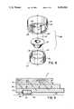
- FIG. 6is a cross-sectional view, similar to FIG. 3, showing a section of a portable floor system supported by a mount constructed in accordance with a second preferred embodiment of the invention.
- FIG. 7is a cross-sectional view of the mount depicted in FIG. 6.
- FIG. 8is a disassembled perspective of the resilient mount shown in FIGS. 6 and 7.
- FIG. 9is a cross sectional view, similar to FIG. 6, showing a variation of the second preferred embodiment of the invention.
- FIG. 10is a bottom view of a floor section equipped with bottom mounted spacing blocks in accordance with another aspect of the invention.
- FIG. 11is a cross sectional view through a plurality of floor sections of the type depicted in FIG. 10, with the sections stacked on a cart.
- FIG. 1is a plan view showing a portable hardwood floor system 10 comprising a plurality of rectangularly shaped connectable sections or modules 11.
- the floor sections 11are either 4' ⁇ 8' or 4' ⁇ 4', with the 4' ⁇ 4' sections located at the ends of the rows of floor sections 11 to provide a staggered arrangement.
- the portable hardwood floor systemmust cover a surface area which is about 112' ⁇ 60'.
- the sections 11 of the portable hardwood floor system 10are stored when not in use. When in use, the sections 11 are interconnected on top of a smooth base floor or substrate, which may be concrete, wood, synthetic or even ice.
- a smooth base floor or substratewhich may be concrete, wood, synthetic or even ice.
- Applicant's U.S. Pat. No. 3,967,428discloses structural details for interconnecting a plurality of portable floor sections 11 and is expressly incorporated by reference herein, in its entirety. Alternately, the floor sections may be interconnected in a manner identical to a current method used to interconnect a portable floor system sold by the assignee of this application under the trademark Cincinnati All-Star Portable.
- the present inventionrelates to a portable floor system 10 equipped with a plurality of resilient mounts secured to a bottom surface of the floor sections 11 for supporting the portable floor 10 in spaced relation above the base.
- the present inventiondoes not relate particularly to the interconnection of the perimeter edges of the floor sections 11.
- FIG. 2shows a portion of a single rectangularly shaped floor section 11.
- the floor section 11includes a wear surface 15 of hard maple floorboards laid end to end, with adjacent rows staggered.
- the floorboards 15 of adjacent rowsare interfitted via a tongue and grove connection.
- the wear surface 15may comprise a plurality of smaller parquet elements arranged in a configuration designed to occupy the same total surface area as the floorboards.
- FIGS. 2 and 3show an upper subfloor 16 of wooden panels residing beneath the wear surface 15, and a lower subfloor 17 of narrow, spaced sleepers residing beneath the upper subfloor 16.
- the upper subfloor 16comprises a single sheet of plywood with a thickness of 1/2" to 3/4".
- the upper subfloor 16 and the lower subfloor 17may be secured together, either by adhesive or mechanical fasteners, such as staples, nails, etc.
- the floorboards 15are secured to the upper subfloor 16 and the lower subfloor 17 by nails driven downwardly at an angle, with the nails driven into the floorboards 15 at the tongues.
- both subfloors 16 and 17are made of panels, to interconnect the floor sections 11 some edge portions of subfloor 16 and/or subfloor 17 may be cut away to accommodate the connecting mechanisms. If either subfloor 16 or 17 is made of narrow, spaced sleepers, the connecting mechanisms may be mounted to the sides of the sleepers, or in between the sleepers.
- one or more of: i) the bottom surface of the wear layer 15; ii) the top and bottom surfaces of the upper subfloor 16, and iii) the top and bottom surfaces of the lower subfloor 17may be kerfed to attenuate the total surface area of deflection upon impact of a load to the floorboards 15. If the floorboards 15 are kerfed, the kerfs should be oriented transverse to the direction of elongation. If both the upper subfloor 16 and the lower subfloor 17 are kerfed, it is preferable that the kerfs of the subfloors 16 and 17 intersect each other.
- a plurality of mountssupport the floor section 11 in spaced relation above the base 19, as shown most clearly in FIG. 3.
- the mounts 18are spaced about one every square foot, and they are secured to a lower surface of the bottommost subfloor 17. This provides uniformity in support and/or resiliency.
- Each mount 18includes, at its bottom, a glide member, designated generally by reference numeral 20, which is substantially noncompressible under normal floor loading conditions.
- the glide members 20also have a relatively low coefficient of friction with respect to the concrete base 19. This enhances maneuverability in positioning and aligning the floor sections 11, thereby facilitating interconnection when forming the composite portable floor system 10.
- a floor section 11 equipped with the glide members 20requires less than half as much force to move laterally. More specifically, on a wood surface, a floor section with no glide member required about 78-80 pounds of horizontally directed force to begin moving, while a floor section 11 equipped with a glide member 20 required only about 38 pounds of force.
- the slidable guide members 20are rigid enough to protect the rubber material of a pad 24 during interconnection and disconnection of the floor sections 11.
- the resilient mounts 18ainclude the compressible and deflectable rubber pad 24 which has a truncated conical shape.
- the pad 24has a flat apex portion 27 spaced from a flat base portion 29.
- the flat base portion 29also includes an opposing pair of ear 28 which facilitate attachment of the pad 24 to the lower surface of the bottommost subfloor layer 17.
- the pad 24is made of ethylene propylene rubber with a hardness ranging from about 45 to 80 durometer on the Shore A scale. Although any other elastomeric or compressible, moldable material would also be sufficient, ethylene propylene is preferred because it is not susceptible to excessive degradation over a period of time.
- each of the pads 24has an internal hollow volume 31 located at base portion 29.
- the hollow volume 31has a cross-sectional area that decreases from base portion 29 to apex portion 27.
- the cross-sectional area of the hollow volume 31is greatest at base portion 29 and decreases in the direction of apex portion 27.
- Volume 31occupies less space than the remainder of the pad 24.
- the pad 24 shown in FIG. 5occupies about 0.645 cubic inches, while volume 31 occupies about 0.043 cubic inches, or about 6.7% of the pad 24 volume. While it is preferable that this volume ratio be about 5% to 15%, it may extend up to 30% or higher, depending on the hardness of the material used to form the pad 24.
- the hollow volume 31is preferably conical in shape, with a downwardly directed apex 33 located at the intersection of interior sidewalls 32.
- the sidewalls 32define an angle 34 which is preferably about 110°. It is noted that there is no coextensive surface contact area between apex portion 27 and base portion 29. That is, no point of surface contact of base portion 29 with subfloor 17 is vertically aligned with any point of surface contact of apex portion 27 with glide member 20a. Moreover, there exists no solid or uninterrupted vertical line of rubber material extending from apex portion 27 to base portion 29 when the pad 24 is in an unloaded condition.
- the pad 24Due to the combination of deflection an compression, and in addition, the elastomeric material used, the pad 24 provides not only a high degree of reflection and resiliency for the floor system 10, but the pads 24 also provide a high degree of vibration dampening that cannot be achieved with any other so called "high deflection" hardwood floors.
- each of the mounts 18ais rendered slidable with respect to the base 19 by a glide member 20a located below apex portion 27.
- the glide member 20ais preferably made by molding, and is of a rigid material such as plastic or nylon, or any other durable material with a similarly low coefficient of friction with respect to concrete substrate 19.
- FIG. 5shows that glide member 20a embedded within pad 24. This may be accomplished by forming the pad 24 by molding with the glide member 20a located in situ in the mold. Alternatively, the glide member 20a may be adhered to apex portion 27 with glue.
- each of the floor sections 11has a high degree of resiliency and uniformity of resiliency.
- the bottom mounted mounts 18afacilitate interconnection and disconnection of the floor sections 11 in a manner which does not inhibit resiliency and in a manner which is not susceptible to degradation as a result of frequent handling by installers.
- the mounts 18awill not be easily knocked off, and the floor sections 11 will not require excessive blows with a rubber mallet to move them into proper position.
- FIGS. 6, 7 and 8show a second preferred embodiment of the invention, wherein the floor sections 11 are supported in spaced relation above the concrete base 19 by mounts 18b which comprise a pair of releasably engagable cups 35 and 36.
- the cups 35 and 36form an encasement of variable vertical dimension for housing and protecting a resilient pad 44 therein.
- the first cups 35are attached to the lower surface of the bottommost subfloor 17 in downwardly opening orientation.
- the second cups 36connect to the first cups 35 in upwardly opening orientation along an axis 45 of connection for the encasement.
- the bottom surface of cup 36serves as the glide surface 20b.
- the cups 35 and 36interconnect via a pair of opposed catches 48 and 49 formed in the first cup 35 which are received in a pair of corresponding, opposed channels 52 and 53, respectively, in the second cup 36.
- a second, smaller pair of opposed channels 56 and 57 in the second cups 36receive elongated guides 58 and 59, respectively, formed on the inside surface of the first cups 35.
- the latches 48 and 49 and the channels 52 and 53define a maximum clearance dimension inside the encasement when there is no compression applied to the cups 35 and 36.
- the vertical dimension of the pad 44is less than this maximum clearance dimension, so that it is not compressed by the interconnected cups 35 and 36 when no compressive force is applied to the cup 35 and 36.
- the vertical dimension of the connected 35 and 36 cupsis reduced upon impact to the floorboards 15 thereabove. The amount of vertical movement depends upon the force applied to the floorboards 15, the compressible and deflectable characteristics of the pad 44 encased therein and the stop mechanism of the cups 35 and 36.
- the vertical dimension between the catches 48 and 49 and an inside top surface 35a of the first cup 35dictates a distance of maximum vertical deflection. Stated another way, the top surface 35, the catches 48 and 49 and a top surface 36a of the second cup 36 act as a stop mechanism to limit vertical deflection.
- the pad 44is preferably similar in shape to pad 24, i.e. a truncated cone, but pad 44 has no ears.
- the cups 35 and 36are preferably molded of nylon or plastic, or another relatively rigid material with a somewhat self-lubricating capability and a low coefficient of friction with respect to base 19 of concrete, wood, synthetic or ice.
- the cups 35 and 36should have some resiliency to allow interconnection without requiring any tools, but sufficient rigidity to require a tool such as a screwdriver to separate the cups 35 and 36.
- the first cups 35preferably have a center hole 60 to allow mechanical connection to the bottom of subfloor 17, as by a staple or other suitable mechanical fastener.
- Side holes 61 and 62may also be used to anchor, though they are actually necessary here to mold the upper cup 35. If desired, any of the holes 60, 61 or 62 may be tapered to limit protrusion of the mechanical fastener into the encasement.
- a void 70 in the top of pad 44is aligned with hole 60, so that if a nail or screw is driven or threaded through hole 60 to secure the first cup 35 to the lower subfloor 17, and the nail or screw does not remain flush with the top surface 35a of first cup 35, protrusion of the nail or screw into the encasement will not impair compressibility or deflectability of the pad 44.
- the mounts 18b formed according to this construction of the inventionprovide resiliency for the portable floor system 10 upon impact to the floorboards 15, uniformity in resiliency, the durability necessitated by frequent interconnection and disconnection, and enhanced maneuverability for aligning the floor sections 11, thereby to facilitate interconnection.
- the second embodimentuses two interconnected cups which encase pad 44 in a cylindrically shaped encasement
- other alternative encasement shapes or configurationswould also be suitable, so long as the resilient pads 44 are carried by the lower surface of the bottommost subfloor 17 and the bottoms of the pads 44 ar protected by glide members 20b which have a low coefficient of friction with respect to the concrete base 19.
- Another advantage of the second embodimentrelates to the open volume between the encasing cups 35 and 36.
- This open volumemay be occupied by a pad 44, as shown in the Figures, for most of the surface area covered by the floor system 10.
- the open volume between the cups 35 and 36may be occupied by a more rigid material such as wood, hardened plastic, etc. Because each of the sections of a portable floor system 10 is always located in the same position of the overall floor system 10 and is always interconnected to the same adjacent sections 11, the encasing cups 35 and 36 can permanently contain these different materials.
- the pad 44 encased between the cups 35 and 36may be changed to suit the activity for which the floor system will be used. For instance, a pad with lower compressible and/or deflectable characteristics may be used for volleyball, compared to basketball, and a pad with higher compression and/or deflection may be used for aerobics.
- FIG. 9shows a mount 20 with a first cup 35 partially countersunk, or partially embedded into subfloor layer 17. Partial embedding protects the mounts 20 because a reduced amount of surface area is exposed. Also, when not in use, the overall height of the stacked sections 11 is less, so that less storage space is required.
- each of the floor sections 11 of the interconnected floor system 10is always located in the same position.
- the separate sections 11are disconnected, loaded onto a cart in a stack, transported to a storage location, and then unloaded, or kept in a stack on the cart. If unloaded, an extra, time-consuming labor step is required.
- the mountswill be subject to vertical compression, an undesirable result because of potential for damage to the mounts, particularly if the mounts include compressible and/or deflectable pads. In the latter case, the pads will prematurely lose their springiness.
- the present inventionsolves this problem by providing spacing blocks 75 secured to the bottom of an upper subfloor 16, between parallel rows of narrow, spaced sleepers which form the lower subfloor 17, as shown in FIG. 10.
- the spacing blocks 75are located away from the mounts 20, and they are arranged perpendicular to the sleepers of the subfloor 17.
- the spacing blocks 75 of adjacently situated floor sections 11are staggered.
- the floor sections 11When stacked on a cart 76, as shown in FIG. 11, the floor sections 11 are always arranged such that top surfaces contact top surfaces and bottom surfaces contact bottom surfaces.
- the sleepers of each of the sections 11a and 11bwill be vertically supported by the spacing blocks 75 of the other one of the sections, 11a or 11b.
- the mounts 20are not subject to vertical compression forces from the weight of the rest of the stack of sections 11. As a result, the pads 24 or 44 are not held in compression.
- This aspect of the inventionworks particularly well if the mounts 10 are partially countersunk within a subfloor 17 of narrow, spaced apart sleepers and the vertical dimensions of the spacing blocks 75 are greater than the vertical protrusion of the mounts 20 from the bottom surface of the subfloor 17. However, this is not absolutely necessary.
- the spacing blocks 75could be slightly thicker than the sleepers and still not interfere with downward deflectability when the floor system is in use.
Landscapes
- Engineering & Computer Science (AREA)
- Architecture (AREA)
- Civil Engineering (AREA)
- Structural Engineering (AREA)
- Life Sciences & Earth Sciences (AREA)
- Wood Science & Technology (AREA)
- Floor Finish (AREA)
Abstract
Description
Claims (17)
Priority Applications (2)
| Application Number | Priority Date | Filing Date | Title |
|---|---|---|---|
| US08/008,721US5303526A (en) | 1989-02-08 | 1993-01-21 | Resilient portable floor system |
| CA002114497ACA2114497C (en) | 1989-02-08 | 1994-01-28 | Resilient portable floor system |
Applications Claiming Priority (6)
| Application Number | Priority Date | Filing Date | Title |
|---|---|---|---|
| US07/308,243US4890434A (en) | 1989-02-08 | 1989-02-08 | Hardwood floor system |
| US45919889A | 1989-12-29 | 1989-12-29 | |
| US76915791A | 1991-09-27 | 1991-09-27 | |
| US07/844,466US5433052A (en) | 1989-02-08 | 1992-03-02 | Kerfed hardwood floor system |
| US08/008,721US5303526A (en) | 1989-02-08 | 1993-01-21 | Resilient portable floor system |
| CA002114497ACA2114497C (en) | 1989-02-08 | 1994-01-28 | Resilient portable floor system |
Related Parent Applications (1)
| Application Number | Title | Priority Date | Filing Date |
|---|---|---|---|
| US07/844,466Continuation-In-PartUS5433052A (en) | 1989-02-08 | 1992-03-02 | Kerfed hardwood floor system |
Related Child Applications (4)
| Application Number | Title | Priority Date | Filing Date |
|---|---|---|---|
| US29023086Division | 1994-05-18 | ||
| US29023085Division | 1994-05-18 | ||
| US29023193Division | 1994-05-18 | ||
| US29023087Division | 1994-05-18 |
Publications (1)
| Publication Number | Publication Date |
|---|---|
| US5303526Atrue US5303526A (en) | 1994-04-19 |
Family
ID=27169693
Family Applications (1)
| Application Number | Title | Priority Date | Filing Date |
|---|---|---|---|
| US08/008,721Expired - LifetimeUS5303526A (en) | 1989-02-08 | 1993-01-21 | Resilient portable floor system |
Country Status (2)
| Country | Link |
|---|---|
| US (1) | US5303526A (en) |
| CA (1) | CA2114497C (en) |
Cited By (33)
| Publication number | Priority date | Publication date | Assignee | Title |
|---|---|---|---|---|
| US5412917A (en)* | 1993-10-14 | 1995-05-09 | Shelton; Floyd | Fixed resilient sleeper athletic flooring system |
| US5465548A (en)* | 1994-03-16 | 1995-11-14 | Robbins, Inc. | Prefabricated sleeper for anchored and resilient hardwood floor system |
| US5465546A (en)* | 1994-05-04 | 1995-11-14 | Buse; Dale C. | Portable dance floor |
| US5682724A (en)* | 1995-09-21 | 1997-11-04 | Connor/Aga Sports Flooring Corporation | Resilient subfloor pad and flooring system employing such a pad |
| WO1998039535A1 (en)* | 1997-03-05 | 1998-09-11 | Connor/Aga Sports Flooring Corporation | Subflooring assembly for athletic playing surface and method of forming the same |
| WO1999006645A1 (en)* | 1997-07-31 | 1999-02-11 | Wheatley Charles E | Outdoor deck material |
| US5899038A (en)* | 1997-04-22 | 1999-05-04 | Mondo S.P.A. | Laminated flooring, for example for sports facilities, a support formation and anchoring systems therefor |
| US6032427A (en)* | 1996-12-13 | 2000-03-07 | Connor Sports Flooring Corporation | Portable panel sports floor system |
| US6044606A (en)* | 1997-08-15 | 2000-04-04 | Horner Flooring, Inc. | Floor system |
| US6199335B1 (en)* | 1998-09-08 | 2001-03-13 | Spaceage Synthetics, Inc. | Floor structure for use on ice and the method of using the same |
| US20030233800A1 (en)* | 1999-08-31 | 2003-12-25 | Monier, Inc. | Elevated batten system |
| US20040140628A1 (en)* | 2003-01-21 | 2004-07-22 | Haymond Bradley J. | Bumper device |
| WO2005033436A1 (en)* | 2003-10-03 | 2005-04-14 | Junckers Industrier A/S | A springing device |
| US6918215B2 (en)* | 2000-08-09 | 2005-07-19 | Longlac Wood Industries Inc. | Free floating sub-floor panel |
| US20050278934A1 (en)* | 2004-03-19 | 2005-12-22 | Brian Orchard | Device and method for fastening structural members |
| US20060185287A1 (en)* | 2005-02-24 | 2006-08-24 | Glazer Kenneth B | Portable floor and method of manufacture and installation |
| EP1790795A1 (en)* | 2005-11-28 | 2007-05-30 | Cuncator AB | Floor System |
| US20070193145A1 (en)* | 2005-12-27 | 2007-08-23 | Wheatley Charles E | Outdoor decking material |
| US20080060305A1 (en)* | 2003-11-20 | 2008-03-13 | Robbins, Inc. | Interlocking Floor |
| US20090126307A1 (en)* | 2007-11-15 | 2009-05-21 | Martin Grohman | Planking system and method |
| US20090235607A1 (en)* | 2008-03-21 | 2009-09-24 | Chen Zhaohong | Deformation-resistant wood flooring |
| WO2011042768A1 (en)* | 2009-10-08 | 2011-04-14 | Petter Brown | Acoustic panel |
| WO2013010581A1 (en) | 2011-07-19 | 2013-01-24 | Tarkett Gdl | Base unit and flooring system. |
| US8464486B1 (en)* | 2009-09-12 | 2013-06-18 | Paul W. Elliott | Contoured floor pads and method |
| US20150075092A1 (en)* | 2013-09-19 | 2015-03-19 | Snapsports Company | Multi-stage shock absorbing modular floor tile apparatus |
| US10011998B1 (en)* | 2017-07-06 | 2018-07-03 | Hugh A. Dantzer | Modular patio assembly |
| US10450760B2 (en) | 2006-01-12 | 2019-10-22 | Valinge Innovation Ab | Floorboards comprising a decorative edge part in a resilient surface layer |
| US10486399B2 (en) | 1999-12-14 | 2019-11-26 | Valinge Innovation Ab | Thermoplastic planks and methods for making the same |
| US10738481B2 (en) | 2009-06-12 | 2020-08-11 | I4F Licensing Nv | Floor panel and floor covering consisting of a plurality of such floor panels |
| US10947741B2 (en) | 2017-04-26 | 2021-03-16 | I4F Licensing Nv | Panel and covering |
| US10975580B2 (en) | 2001-07-27 | 2021-04-13 | Valinge Innovation Ab | Floor panel with sealing means |
| US20210355691A1 (en)* | 2020-03-09 | 2021-11-18 | Spencer Gavin Hering | Modular Sprung Floor |
| US20230096329A1 (en)* | 2020-10-26 | 2023-03-30 | Magic Shields Inc. | Impact absorbing flooring |
Citations (32)
| Publication number | Priority date | Publication date | Assignee | Title |
|---|---|---|---|---|
| IT427830A (en)* | ||||
| US1477331A (en)* | 1920-02-26 | 1923-12-11 | Corona Typewriter Co Inc | Cushioning device |
| US2088238A (en)* | 1935-06-12 | 1937-07-27 | Harris Mfg Company | Wood flooring |
| US2477071A (en)* | 1944-04-15 | 1949-07-26 | Matti Kurt Gunter | Parquet floor |
| US2569709A (en)* | 1946-10-16 | 1951-10-02 | Elmendorf Armin | Method of making a flexible wood floor covering |
| CA485372A (en)* | 1952-08-05 | Kahr Gustaf | Composite floors | |
| US2634464A (en)* | 1948-07-23 | 1953-04-14 | Storm Flooring Co Inc | Flooring element |
| CA565012A (en)* | 1958-10-21 | United-Carr Fastener Corporation | Support | |
| US2893665A (en)* | 1953-04-25 | 1959-07-07 | Luxembourg Brev Participations | Resilient suspension devices |
| US2919476A (en)* | 1955-08-06 | 1960-01-05 | Fritz Bernhard | Spring floors |
| GB835758A (en)* | 1955-08-06 | 1960-05-25 | Bernhard Fritz | Improvements in or relating to spring floors |
| CH353158A (en)* | 1955-08-06 | 1961-03-31 | Bernhard Prof Dr Ing Fritz | Floor |
| US3107377A (en)* | 1959-09-18 | 1963-10-22 | Hamilton Kent Mfg Company | Bridge pad and its use |
| DE1157367B (en)* | 1960-03-03 | 1963-11-14 | Bembe Parkett Fabrik Jucker & | Swing bars for swing floors as well as swing floors with such swing bars |
| CA675982A (en)* | 1963-12-17 | Fritz Bernhard | Spring floors | |
| AT240020B (en)* | 1962-11-22 | 1965-05-10 | Semperit Ag | Stable flooring made of elastic material |
| US3273296A (en)* | 1963-06-17 | 1966-09-20 | Glenn E Soulon | Detachable baseboard and flooring trim assembly |
| US3279138A (en)* | 1965-07-02 | 1966-10-18 | Cromar Company | Surface finishing panel |
| US3288405A (en)* | 1964-10-08 | 1966-11-29 | Kenneth W Johnson | Vibration isolator |
| US3337167A (en)* | 1966-07-11 | 1967-08-22 | Kenneth W Johnson | Vibration isolator |
| DE1255900B (en)* | 1959-03-10 | 1967-12-07 | Ind F P Hamberger G M B H | Resilient floor, especially for gyms |
| US3368806A (en)* | 1965-02-19 | 1968-02-13 | Cellasto Inc | Graduated pressure spring element made of elastomer material |
| US3417950A (en)* | 1966-07-11 | 1968-12-24 | Kenneth W. Johnson | Vibration isolator |
| US3579410A (en)* | 1967-09-06 | 1971-05-18 | American Novawood Corp | Parquet flooring block and method of making same |
| US3579941A (en)* | 1968-11-19 | 1971-05-25 | Howard C Tibbals | Wood parquet block flooring unit |
| DE2053588A1 (en)* | 1970-10-31 | 1972-05-04 | Dynamit Nobel Ag, 5210 Troisdorf | Composite flooring element and method of laying it |
| DE2221761A1 (en)* | 1972-05-04 | 1973-11-15 | Lieselotte Hofmann | FLOOR |
| US3908053A (en)* | 1972-05-18 | 1975-09-23 | Karl Hettich | Finished parquet element |
| DE2609792A1 (en)* | 1976-03-10 | 1977-09-15 | Richard Reuther | Resilient floating gymnasium floor - has interlocking cover panels with light elastic layer between unbendable brittle layers |
| US4682459A (en)* | 1986-04-15 | 1987-07-28 | Stephenson Debra A | Flooring system |
| US4879857A (en)* | 1985-06-13 | 1989-11-14 | Sport Floor Design, Inc. | Resilient leveler and shock absorber for sport floor |
| US4890434A (en)* | 1989-02-08 | 1990-01-02 | Robbins, Inc. | Hardwood floor system |
- 1993
- 1993-01-21USUS08/008,721patent/US5303526A/ennot_activeExpired - Lifetime
- 1994
- 1994-01-28CACA002114497Apatent/CA2114497C/ennot_activeExpired - Lifetime
Patent Citations (32)
| Publication number | Priority date | Publication date | Assignee | Title |
|---|---|---|---|---|
| CA675982A (en)* | 1963-12-17 | Fritz Bernhard | Spring floors | |
| CA485372A (en)* | 1952-08-05 | Kahr Gustaf | Composite floors | |
| CA565012A (en)* | 1958-10-21 | United-Carr Fastener Corporation | Support | |
| IT427830A (en)* | ||||
| US1477331A (en)* | 1920-02-26 | 1923-12-11 | Corona Typewriter Co Inc | Cushioning device |
| US2088238A (en)* | 1935-06-12 | 1937-07-27 | Harris Mfg Company | Wood flooring |
| US2477071A (en)* | 1944-04-15 | 1949-07-26 | Matti Kurt Gunter | Parquet floor |
| US2569709A (en)* | 1946-10-16 | 1951-10-02 | Elmendorf Armin | Method of making a flexible wood floor covering |
| US2634464A (en)* | 1948-07-23 | 1953-04-14 | Storm Flooring Co Inc | Flooring element |
| US2893665A (en)* | 1953-04-25 | 1959-07-07 | Luxembourg Brev Participations | Resilient suspension devices |
| GB835758A (en)* | 1955-08-06 | 1960-05-25 | Bernhard Fritz | Improvements in or relating to spring floors |
| CH353158A (en)* | 1955-08-06 | 1961-03-31 | Bernhard Prof Dr Ing Fritz | Floor |
| US2919476A (en)* | 1955-08-06 | 1960-01-05 | Fritz Bernhard | Spring floors |
| DE1255900B (en)* | 1959-03-10 | 1967-12-07 | Ind F P Hamberger G M B H | Resilient floor, especially for gyms |
| US3107377A (en)* | 1959-09-18 | 1963-10-22 | Hamilton Kent Mfg Company | Bridge pad and its use |
| DE1157367B (en)* | 1960-03-03 | 1963-11-14 | Bembe Parkett Fabrik Jucker & | Swing bars for swing floors as well as swing floors with such swing bars |
| AT240020B (en)* | 1962-11-22 | 1965-05-10 | Semperit Ag | Stable flooring made of elastic material |
| US3273296A (en)* | 1963-06-17 | 1966-09-20 | Glenn E Soulon | Detachable baseboard and flooring trim assembly |
| US3288405A (en)* | 1964-10-08 | 1966-11-29 | Kenneth W Johnson | Vibration isolator |
| US3368806A (en)* | 1965-02-19 | 1968-02-13 | Cellasto Inc | Graduated pressure spring element made of elastomer material |
| US3279138A (en)* | 1965-07-02 | 1966-10-18 | Cromar Company | Surface finishing panel |
| US3337167A (en)* | 1966-07-11 | 1967-08-22 | Kenneth W Johnson | Vibration isolator |
| US3417950A (en)* | 1966-07-11 | 1968-12-24 | Kenneth W. Johnson | Vibration isolator |
| US3579410A (en)* | 1967-09-06 | 1971-05-18 | American Novawood Corp | Parquet flooring block and method of making same |
| US3579941A (en)* | 1968-11-19 | 1971-05-25 | Howard C Tibbals | Wood parquet block flooring unit |
| DE2053588A1 (en)* | 1970-10-31 | 1972-05-04 | Dynamit Nobel Ag, 5210 Troisdorf | Composite flooring element and method of laying it |
| DE2221761A1 (en)* | 1972-05-04 | 1973-11-15 | Lieselotte Hofmann | FLOOR |
| US3908053A (en)* | 1972-05-18 | 1975-09-23 | Karl Hettich | Finished parquet element |
| DE2609792A1 (en)* | 1976-03-10 | 1977-09-15 | Richard Reuther | Resilient floating gymnasium floor - has interlocking cover panels with light elastic layer between unbendable brittle layers |
| US4879857A (en)* | 1985-06-13 | 1989-11-14 | Sport Floor Design, Inc. | Resilient leveler and shock absorber for sport floor |
| US4682459A (en)* | 1986-04-15 | 1987-07-28 | Stephenson Debra A | Flooring system |
| US4890434A (en)* | 1989-02-08 | 1990-01-02 | Robbins, Inc. | Hardwood floor system |
Cited By (54)
| Publication number | Priority date | Publication date | Assignee | Title |
|---|---|---|---|---|
| US5412917A (en)* | 1993-10-14 | 1995-05-09 | Shelton; Floyd | Fixed resilient sleeper athletic flooring system |
| US5465548A (en)* | 1994-03-16 | 1995-11-14 | Robbins, Inc. | Prefabricated sleeper for anchored and resilient hardwood floor system |
| US5465546A (en)* | 1994-05-04 | 1995-11-14 | Buse; Dale C. | Portable dance floor |
| US5682724A (en)* | 1995-09-21 | 1997-11-04 | Connor/Aga Sports Flooring Corporation | Resilient subfloor pad and flooring system employing such a pad |
| US6397543B1 (en) | 1996-08-15 | 2002-06-04 | Douglas J Hamar | Floor system |
| US6931808B2 (en)* | 1996-08-15 | 2005-08-23 | Douglas J Hamar | Floor system |
| US6032427A (en)* | 1996-12-13 | 2000-03-07 | Connor Sports Flooring Corporation | Portable panel sports floor system |
| WO1998039535A1 (en)* | 1997-03-05 | 1998-09-11 | Connor/Aga Sports Flooring Corporation | Subflooring assembly for athletic playing surface and method of forming the same |
| US5899038A (en)* | 1997-04-22 | 1999-05-04 | Mondo S.P.A. | Laminated flooring, for example for sports facilities, a support formation and anchoring systems therefor |
| US6418690B1 (en) | 1997-07-31 | 2002-07-16 | Chalres E. Wheatley | Outdoor deck material |
| WO1999006645A1 (en)* | 1997-07-31 | 1999-02-11 | Wheatley Charles E | Outdoor deck material |
| US6044606A (en)* | 1997-08-15 | 2000-04-04 | Horner Flooring, Inc. | Floor system |
| US6199335B1 (en)* | 1998-09-08 | 2001-03-13 | Spaceage Synthetics, Inc. | Floor structure for use on ice and the method of using the same |
| US20030233800A1 (en)* | 1999-08-31 | 2003-12-25 | Monier, Inc. | Elevated batten system |
| US10486399B2 (en) | 1999-12-14 | 2019-11-26 | Valinge Innovation Ab | Thermoplastic planks and methods for making the same |
| US6918215B2 (en)* | 2000-08-09 | 2005-07-19 | Longlac Wood Industries Inc. | Free floating sub-floor panel |
| US10975580B2 (en) | 2001-07-27 | 2021-04-13 | Valinge Innovation Ab | Floor panel with sealing means |
| US7243395B2 (en)* | 2003-01-21 | 2007-07-17 | Illinois Tool Works Inc | Bumper device |
| US20040140628A1 (en)* | 2003-01-21 | 2004-07-22 | Haymond Bradley J. | Bumper device |
| CN100404771C (en)* | 2003-10-03 | 2008-07-23 | 容克斯工业公司 | A springing device |
| WO2005033436A1 (en)* | 2003-10-03 | 2005-04-14 | Junckers Industrier A/S | A springing device |
| US20080060305A1 (en)* | 2003-11-20 | 2008-03-13 | Robbins, Inc. | Interlocking Floor |
| US8291661B2 (en)* | 2003-11-20 | 2012-10-23 | Robbins, Inc. | Interlocking floor |
| US20050278934A1 (en)* | 2004-03-19 | 2005-12-22 | Brian Orchard | Device and method for fastening structural members |
| US20060185287A1 (en)* | 2005-02-24 | 2006-08-24 | Glazer Kenneth B | Portable floor and method of manufacture and installation |
| EP1790795A1 (en)* | 2005-11-28 | 2007-05-30 | Cuncator AB | Floor System |
| US20070193145A1 (en)* | 2005-12-27 | 2007-08-23 | Wheatley Charles E | Outdoor decking material |
| US10450760B2 (en) | 2006-01-12 | 2019-10-22 | Valinge Innovation Ab | Floorboards comprising a decorative edge part in a resilient surface layer |
| US11702847B2 (en) | 2006-01-12 | 2023-07-18 | Valinge Innovation Ab | Floorboards comprising a decorative edge part in a resilient surface layer |
| US11066836B2 (en) | 2006-01-12 | 2021-07-20 | Valinge Innovation Ab | Floorboards comprising a decorative edge part in a resilient surface layer |
| US7644556B2 (en)* | 2007-11-15 | 2010-01-12 | Correct Building Products, L.L.C. | Planking system and method |
| US20090126307A1 (en)* | 2007-11-15 | 2009-05-21 | Martin Grohman | Planking system and method |
| US20090235607A1 (en)* | 2008-03-21 | 2009-09-24 | Chen Zhaohong | Deformation-resistant wood flooring |
| US11668100B2 (en) | 2009-06-12 | 2023-06-06 | I4F Licensing Nv | Floor panel and floor covering consisting of a plurality of such floor panels |
| US10738480B2 (en) | 2009-06-12 | 2020-08-11 | I4F Licensing Nv | Floor panel and floor covering consisting of a plurality of such floor panels |
| US10738482B2 (en) | 2009-06-12 | 2020-08-11 | I4F Licensing Nv | Floor panel and floor covering consisting of a plurality of such floor panels |
| US10738481B2 (en) | 2009-06-12 | 2020-08-11 | I4F Licensing Nv | Floor panel and floor covering consisting of a plurality of such floor panels |
| US8464486B1 (en)* | 2009-09-12 | 2013-06-18 | Paul W. Elliott | Contoured floor pads and method |
| WO2011042768A1 (en)* | 2009-10-08 | 2011-04-14 | Petter Brown | Acoustic panel |
| WO2013010581A1 (en) | 2011-07-19 | 2013-01-24 | Tarkett Gdl | Base unit and flooring system. |
| US10214922B2 (en)* | 2013-09-19 | 2019-02-26 | Snapsports Company | Multi-stage shock absorbing modular floor tile apparatus |
| US9790691B2 (en) | 2013-09-19 | 2017-10-17 | Snapsports Company | Multi-stage shock absorbing modular floor tile apparatus |
| US20160010343A1 (en)* | 2013-09-19 | 2016-01-14 | Snapsports Company | Multi-stage shock absorbing modular floor tile apparatus |
| US20150075092A1 (en)* | 2013-09-19 | 2015-03-19 | Snapsports Company | Multi-stage shock absorbing modular floor tile apparatus |
| US9909323B2 (en)* | 2013-09-19 | 2018-03-06 | Snapsports Company | Multi-stage shock absorbing modular floor tile apparatus |
| US9133628B2 (en)* | 2013-09-19 | 2015-09-15 | Snapsports Company | Multi-stage shock absorbing modular floor tile apparatus |
| US9458636B2 (en)* | 2013-09-19 | 2016-10-04 | Snapsports Company | Multi-stage shock absorbing modular floor tile apparatus |
| US10947741B2 (en) | 2017-04-26 | 2021-03-16 | I4F Licensing Nv | Panel and covering |
| US11441319B2 (en) | 2017-04-26 | 2022-09-13 | I4F Licensing Nv | Panel and covering |
| US10011998B1 (en)* | 2017-07-06 | 2018-07-03 | Hugh A. Dantzer | Modular patio assembly |
| US20210355691A1 (en)* | 2020-03-09 | 2021-11-18 | Spencer Gavin Hering | Modular Sprung Floor |
| US11655639B2 (en)* | 2020-03-09 | 2023-05-23 | Spencer Gavin Hering | Modular sprung floor |
| US20230096329A1 (en)* | 2020-10-26 | 2023-03-30 | Magic Shields Inc. | Impact absorbing flooring |
| US12366075B2 (en)* | 2020-10-26 | 2025-07-22 | Magic Shields Inc. | Impact absorbing flooring |
Also Published As
| Publication number | Publication date |
|---|---|
| CA2114497A1 (en) | 1995-07-29 |
| CA2114497C (en) | 2004-03-30 |
Similar Documents
| Publication | Publication Date | Title |
|---|---|---|
| US5303526A (en) | Resilient portable floor system | |
| US6931808B2 (en) | Floor system | |
| US5682724A (en) | Resilient subfloor pad and flooring system employing such a pad | |
| US8505256B2 (en) | Synthetic floor tile having partially-compliant support structure | |
| US5761867A (en) | Tile support insert | |
| US5566930A (en) | Kerfed hardwood floor system | |
| US7127857B2 (en) | Subfloor assembly for athletic playing surface having improved deflection characteristics | |
| US5992106A (en) | Hexagon tile with equilateral reinforcement | |
| US4890434A (en) | Hardwood floor system | |
| US4860516A (en) | Portable cushioned floor system | |
| JP2863647B2 (en) | Elastic exercise floor | |
| US5365710A (en) | Resilient subfloor pad | |
| US20140237916A1 (en) | Modular floor tile with resilient support members | |
| WO2000008273A9 (en) | Hexagon tile with equilateral reinforcement | |
| CN106661892B (en) | Vibration damping floor system | |
| CA2799109C (en) | Base flooring and flooring system | |
| KR20060136292A (en) | Assembling flooring member | |
| EP2331771B1 (en) | Sub-floor assemblies for sports flooring systems | |
| US4913433A (en) | Protective lining for bowling alley | |
| US20210396025A1 (en) | Modular flooring system and subfloor assembly | |
| KR200408056Y1 (en) | Prefab parquet flooring | |
| HK1232576A1 (en) | Vibration dampening floor system | |
| JP2002310461A (en) | Pedestal for installation of instrument |
Legal Events
| Date | Code | Title | Description |
|---|---|---|---|
| AS | Assignment | Owner name:ROBBINS, INC., OHIO Free format text:ASSIGNMENT OF ASSIGNORS INTEREST.;ASSIGNOR:NIESE, MICHAEL W.;REEL/FRAME:006432/0753 Effective date:19930119 | |
| STCF | Information on status: patent grant | Free format text:PATENTED CASE | |
| FPAY | Fee payment | Year of fee payment:4 | |
| FEPP | Fee payment procedure | Free format text:PAT HOLDER CLAIMS SMALL ENTITY STATUS, ENTITY STATUS SET TO SMALL (ORIGINAL EVENT CODE: LTOS); ENTITY STATUS OF PATENT OWNER: SMALL ENTITY | |
| REFU | Refund | Free format text:REFUND - PAYMENT OF MAINTENANCE FEE, 8TH YEAR, LARGE ENTITY (ORIGINAL EVENT CODE: R184); ENTITY STATUS OF PATENT OWNER: SMALL ENTITY | |
| FPAY | Fee payment | Year of fee payment:8 | |
| FPAY | Fee payment | Year of fee payment:12 | |
| AS | Assignment | Owner name:KEYBANK NATIONAL ASSOCIATION, OHIO Free format text:SECURITY AGREEMENT;ASSIGNOR:ROBBINS, INC.;REEL/FRAME:018039/0291 Effective date:20060726 | |
| AS | Assignment | Owner name:ROBBINS, INC., OHIO Free format text:RELEASE BY SECURED PARTY;ASSIGNOR:KEYBANK NATIONAL ASSOCIATION;REEL/FRAME:037231/0585 Effective date:20140821 | |
| AS | Assignment | Owner name:CAPITAL BUSINESS CREDIT LLC, NORTH CAROLINA Free format text:SECURITY INTEREST;ASSIGNOR:ROBBINS, INC.;REEL/FRAME:037332/0948 Effective date:20151214 | |
| AS | Assignment | Owner name:ROBBINS, INC., OHIO Free format text:RELEASE BY SECURED PARTY;ASSIGNOR:WHITE OAK COMMERCIAL FINANCE, LLC;REEL/FRAME:047882/0870 Effective date:20181210 |