US5303171A - System suspend on lid close and system resume on lid open - Google Patents
System suspend on lid close and system resume on lid openDownload PDFInfo
- Publication number
- US5303171A US5303171AUS07/865,048US86504892AUS5303171AUS 5303171 AUS5303171 AUS 5303171AUS 86504892 AUS86504892 AUS 86504892AUS 5303171 AUS5303171 AUS 5303171A
- Authority
- US
- United States
- Prior art keywords
- processor
- lid
- operational mode
- main processor
- movement
- Prior art date
- Legal status (The legal status is an assumption and is not a legal conclusion. Google has not performed a legal analysis and makes no representation as to the accuracy of the status listed.)
- Expired - Lifetime
Links
Images


Classifications
- G—PHYSICS
- G06—COMPUTING OR CALCULATING; COUNTING
- G06F—ELECTRIC DIGITAL DATA PROCESSING
- G06F1/00—Details not covered by groups G06F3/00 - G06F13/00 and G06F21/00
- G06F1/26—Power supply means, e.g. regulation thereof
- G06F1/32—Means for saving power
- G06F1/3203—Power management, i.e. event-based initiation of a power-saving mode
- G06F1/3234—Power saving characterised by the action undertaken
- G06F1/324—Power saving characterised by the action undertaken by lowering clock frequency
- G—PHYSICS
- G06—COMPUTING OR CALCULATING; COUNTING
- G06F—ELECTRIC DIGITAL DATA PROCESSING
- G06F1/00—Details not covered by groups G06F3/00 - G06F13/00 and G06F21/00
- G06F1/24—Resetting means
- G—PHYSICS
- G06—COMPUTING OR CALCULATING; COUNTING
- G06F—ELECTRIC DIGITAL DATA PROCESSING
- G06F1/00—Details not covered by groups G06F3/00 - G06F13/00 and G06F21/00
- G06F1/26—Power supply means, e.g. regulation thereof
- G06F1/32—Means for saving power
- G06F1/3203—Power management, i.e. event-based initiation of a power-saving mode
- Y—GENERAL TAGGING OF NEW TECHNOLOGICAL DEVELOPMENTS; GENERAL TAGGING OF CROSS-SECTIONAL TECHNOLOGIES SPANNING OVER SEVERAL SECTIONS OF THE IPC; TECHNICAL SUBJECTS COVERED BY FORMER USPC CROSS-REFERENCE ART COLLECTIONS [XRACs] AND DIGESTS
- Y02—TECHNOLOGIES OR APPLICATIONS FOR MITIGATION OR ADAPTATION AGAINST CLIMATE CHANGE
- Y02D—CLIMATE CHANGE MITIGATION TECHNOLOGIES IN INFORMATION AND COMMUNICATION TECHNOLOGIES [ICT], I.E. INFORMATION AND COMMUNICATION TECHNOLOGIES AIMING AT THE REDUCTION OF THEIR OWN ENERGY USE
- Y02D10/00—Energy efficient computing, e.g. low power processors, power management or thermal management
Definitions
- This inventionrelates to a portable computer having a lid movable between open and closed position and, more particularly, relates to the action taken when the lid is moved from the open position to the closed position while the computer system is operating.
- Portable computers of the type commonly referred to as “laptop” computers and “notebook” computersare becoming very popular They typically include a housing with a lid which is movable between open and closed positions, a display which is mounted on the lid, and a keyboard which is mounted on the housing beneath the lid, the keyboard and display being exposed when the lid is in the open position and being hidden and protected when the lid is in the closed position
- These systemsalso include a battery which serves as a source of power. If a user inadvertently closes the lid without remembering to turn off the power, the system can continue to operate and will run down the battery.
- An alternative known approachis to respond to the close of the lid by producing an audible beep rather than shutting off power to the system. This permits the user to reopen the lid and continue operation without any loss of data or program information. Nevertheless, if the user does not hear the beep or forgets to open the lid following the beep, the battery may run down and cause the contents of the semiconductor memory to be lost.
- a recently-developed microprocessorhas the capability to save the status of an operating computer system, then shut off power to almost all of the system, and then enter a low power suspend state, and has the capability to exit the suspend state at a subsequent time, restore power to the system, restore the saved state of the system, and then resume operation from the point at which the system was interrupted.
- systems using this microprocessorhave effected entry to and exit from the suspend mode based on a manually operable push-button switch or on other internal criteria such as expiration of a timer.
- closing of the lid during system operationresults only in generation of an audible beep, with the same disadvantages mentioned above.
- An object of the inventionis therefore to provide an arrangement for causing a system to enter and subsequently exit suspend mode in response to closing and subsequent opening of a lid.
- a computer systemwhich includes a housing, a lid supported on the housing for movement between open and closed positions, a processor provided in the housing and having a first operational mode in which the processor executes instructions and a second operational mode in which the processor is halted in a reduced power state from which the processor can automatically exit in response to a predetermined condition.
- the systemincludes an arrangement responsive to movement of the lid to its closed position when the processor is in its first operational mode for switching the processor to its second operational mode.
- a computer systemincludes a housing, a lid supported on the housing for movement between open and closed positions, a processor having a first operational mode in which the processor executes instructions and a second operational mode in which the processor is halted in a reduced power state from which the processor can automatically exit in response to a predetermined condition.
- This systemincludes an arrangement for permitting an operator to select one of first and second events to occur when the lid is moved to its closed position, the first event being switching of the processor from the first operational mode to the second operational mode.
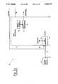
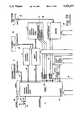
- FIGS. 1a, 1b, 1c and 1dwhich are collectively referred to herein as FIG. 1, show a block diagram of a computer system embodying the present invention
- FIGS. 2 and 3are flowcharts of selected program segments executed by an auxiliary processor of the system of FIG. 1;
- FIGS. 4-8are flowcharts of selected program segments executed by a main processor of the system of FIG. 1.
- FIGS. 1a, 1b, 1c and 1dwhich are collectively referred to herein as FIG. 1, show is a block diagram of a "notebook" type laptop computer system 10 which embodies features of the present invention.
- the computer system 10includes a main processor 11, a power control circuit 12, a signal processing circuit 13, a manually operable power control switch 16, a system control processor (SCP) 17, an internal keyboard 18, a video controller 19, a monochrome liquid crystal display (LCD) 21, a modem 22, a hard disk drive 23, a main memory 24 implemented with dynamic random access memory (DRAM) chips, a floppy disk drive 26, a read only memory (ROM) 27, and a flash RAM 28.
- DRAMdynamic random access memory
- the main processor 11is implemented with an Intel 386SL, which is a conventional component commercially available from Intel Corporation of Santa Clara, Calif.
- Intel 386SLis a conventional component commercially available from Intel Corporation of Santa Clara, Calif.
- This microprocessorhas certain special features which are described in U.S. Ser. No. 07/752 342 filed Aug. 30, 1991, which is a continuation-in-part of U.S. Ser. No. 07/705 039 filed May 17, 1991.
- the disclosures of each of these prior applicationsare hereby incorporated herein by reference.
- Detailed information regarding the Intel 386SLis also available directly from Intel, and the entire internal architecture thereof is therefore not shown and described in detail here. Those features of the processor which are pertinent to the present invention are briefly described here.
- the main processor 11includes a clock generator 31 which generates respective clocks for various components of the system, including the processor 11 itself, and which is controlled by a speed control register 32.
- the processor 11 and some other system componentsare of a type which use more power when running at a higher clock speed than when running at a lower clock speed. Therefore, clocks can be set to a higher speed when rapid processing is required despite the fact that a larger amount of power is drawn from the system battery during a given time period, whereas when processing speed is not critical a lower clock speed can be used in order to reduce the amount of power being drawn from the battery.
- a refresh control circuit 33controls the rate at which the data stored in the main memory 24 is refreshed. The slower the refresh rate, the lower the power consumption by the main memory 24.
- the refresh ratecan be set to a very low rate in which the memory 24 uses minimal power, but at this low rate it is not possible to read or write data to or from the memory 24.
- the processor 11also includes a power management interrupt (PMI) generator 36, which generates a special PMI interrupt in response to several conditions, three of which are shown in FIG. 1. The first is the occurrence of a signal on a line 37 in response to manual actuation of the manual switch 16, the second is a signal EXT PMI on a line 38 from an external source, and the third is an interrupt which is internally generated by software running in the processor 11 and which is indicated diagrammatically at 39.
- PMIpower management interrupt
- the hardware in the processor 11automatically saves the current internal state of the processor 11 in a special portion 40 of the memory 24. Then, the processor automatically begins execution of a special interrupt routine, which is described later. Upon completion of the interrupt routine, a restore instruction automatically restores the state of the processor 11 from the portion 40 of the memory 24, and causes the processor 11 to resume operation from the point at which it was interrupted.
- the processor 11has several conventional modes of operation, one of which is an "unprotected” mode in which the program running in the processor 11 has access to all operational capabilities of the processor 11, whereas the other modes are “protected” modes in which the program running in the processor 11 has different degrees of accessibility to the operational capabilities.
- the occurrence of a PMI interruptautomatically forces the processor into the unprotected mode of operation, while the restore instruction will restore the processor to the mode of operation which it was in at the time the PMI interrupt occurred.
- an application program which is running in one of the protected modescan be interrupted, the processor can carry out various functions in the unprotected mode without any of the limitations which would be present in one of the protected modes, and then the application program can be resumed from the point at which it was interrupted with its own protected mode back in effect.
- the processor 11When an application program has been interrupted, the processor 11 has the capability to enter a suspend or rest mode, in which it causes the power control circuit 12 to shut off power to most other components in the system, and then turns off its own clock in order to enter a very low power mode.
- the systemcan be in the suspend mode for a very short period of time, or for several weeks (if the batteries are fully charged when suspend is entered).
- the processorturns its clock back on, causes the power control circuit 12 to restore power to other components, and then returns to the interrupted application program.
- a resume control circuit 41is responsible for causing the processor 11 to resume from the suspend mode.
- the resume control circuit 41is responsive to several conditions, two of which are shown in FIG. 1.
- the firstis an output signal on line 42 from the signal processing circuit 13, which is described in more detail later.
- the otheris a modem ring indicator signal MDMRI on a line 43 from the modem 22.
- the resume control circuit 41produces a resume reset which internally resets the main processor 11 and which also sets a resume flag 44.
- the resume flag 44remains set in order to provide an indication to the software that the reset was the result of a resume event and not a standard system reset of the type which occurs when power is first applied to the system.
- the resetcauses the processor to begin executing a special software routine in the flash RAM 28, as described in more detail later.
- the processer 11also includes a bus control circuit 46 to control a bus 47, which includes address, control and data lines, and which couples the processor 11 to other major system components.
- the power control circuit 12includes batteries 51, and has a connector 52 to which can be attached an AC to DC converter 53.
- the power control circuit 12has a power output PMVCC on which it supplies power to the processor 11, main memory 24 and signal processing circuit 13, and has a power output SYSVCC on which it supplies power to other system components.
- the power control circuit 12is controlled at 54 by the main processor 11.
- the SCP in the preferred embodimentis based on an Intel 87C51GB microprocessor, but it will be recognized that there are other commercially available microprocessors which could also be used for the SCP.
- the SCPcan generate a speaker control signal on a line 56 which is connected to a speaker 57, which can cause the speaker 57 to produce an audible beep.
- the speaker 57can respond in a similar manner to a signal produced by the main processor 11 on a line 58.
- the SCPreceives from the main processor 11 a signal CPUSUREQ, which the main processor actuates just before it sends a command to the SCP.
- the SCP 17includes a RAM 79 in which the SCP can store and retrieve information during system operation.
- the SCPalso includes several input/output (I/O) registers 81, which are used to pass data between the main processor 11 and the SCP 17.
- I/Oinput/output
- the SCP 17is coupled to an external connector 61, to which can optionally be coupled a conventional mouse or external keyboard 62.
- the SCPis also coupled at 63 to the internal keyboard 18, and is coupled at 64 to the video controller 19.
- the video controller 19is coupled to a connector 65, to which can optionally be coupled a conventional external CRT display 66.
- the video controller 19is also coupled to the LCD 21.
- the SCPsends to the LCD 21 a signal LCDPWR, which turns on and off the power to the liquid crystal display in the unit 321.
- the displayincludes a backlight 67 which illuminates the liquid crystal display.
- the display unitis provided on a lid of the laptop computer which, in a conventional manner, can be moved between positions covering and exposing the keys of the internal keyboard 18, the liquid crystal display 21 being visible and hidden when the lid is respectively in the open and closed positions.
- the SCP 17generates a signal BLON which turns on and off the backlight 67.
- a lid switch 68is provided to indicate whether the lid is open or closed, and sends an appropriate signal on a line LIDSW to the SCP 17.
- the SCP 17also generates a signal MDMEN which causes the power control section of the modem 22 to selectively provide power to the modem or to shut off power to the modem (or at least place the modem in a low power consumption state).
- the SCP 17receives from the modem 322 the previously-mentioned modem ring indicator signal MDMRI, which is actuated when an incoming telephone call reaches the modem through a telephone jack 69 to which the modem is coupled, the jack 69 being adapted to be optionally coupled to a standard telephone line 71.
- the hard disk drive 23produces an output signal LED which is used in a conventional manner to control a conventional and not-illustrated light emitting diode in order to provide the computer user with a visual indication of the activity of the hard disk drive.
- This LED signalis connected to the SCP and to one input of a two-input AND gate 72, the hard disk not busy output HDNB of which is connected to one input of a two-input OR gate 73 and indicates that the hard disk is not busy.
- the other input of the AND gate 72is connected to an ENABLE output signal of the SCP 17, and thus the SCP can selectively enable and disable the gate 72.
- the SCPalso produces an output signal at 74 which is connected to a second input of the OR gate 73, the output of the OR gate 73 being the previously-mentioned EXT PMI signal to the main processor 11.
- a register 77is coupled to the bus 47 and produces an output on a line 78 which is coupled to an input of the signal processing circuit 13 and which is discussed in more detail later.
- the flash RAM 28is a conventional semiconductor device which can be electrically modified, but is not volatile and will retain the information stored in it when power to it is turned off.
- the flash RAMcontains the basic input/output system (BIOS) program.
- the ROM 27contains a program which is normally not used, but which can be used to control the system while the flash RAM 28 is reloaded in the event an unusual circumstance causes the contents of the flash RAM to be lost.
- the floppy disk drive 26is conventional in all respects, and not described in detail.
- the signal processing circuit 13includes an R/C divider 86 tied to the LIDSW output from the lid switch 68, and an inverter 87 which has an input connected to the signal LIDSW.
- the output 88 of the inverteris connected to one input of a two-input exclusive-OR gate 89, and through a resistor 90 to an input of a further inverter 91.
- the output of inverter 91is coupled through a resistor 92 to the other input of the gate 89, which is coupled to ground by a capacitor 93.
- the output of the gate 89is connected to the trigger input of a monostable multivibrator or "one-shot" 96, the time period of which is controlled by an R/C network 97.
- the lid switch 68When the lid switch 68 closes or opens, the change in the state of its output signal LIDSW is applied through inverter 87 on line 88 to one input of the gate 89, causing the output of gate 89 to change, and a short period of time later is applied through resistor 90, inverter 91 and resistor 92 to the other input of the gate 89, causing the output of the gate 89 to return to its original state.
- the exclusive OR gate 89will produce a pulse equal in length to the propogation delay through the circuit branch containing resistor 90, inverter 91, resistor 92 and capacitor 93.
- This pulsewill trigger the one-shot 96, so that it produces an output which is applied to one input of an OR gate 98, the other input of which is coupled to the output 37 from the manual switch 16.
- the output of the OR gate 98is the line 42, which is connected to the resume control portion 41 of the main processor 11.
- the signal processing circuit 13also includes a D-type flip-flop 101 having a clock input to which is coupled the line 78 from the register 77.
- the inverted output of the flip-flopis connected to the D input, so that the flip-flop changes state or "toggles" each time the signal on line 78 changes from a logic low to a logic high.
- the output of the flip-flop 101is connected to a reset input of the one-shot 96. Consequently, by appropriately controlling the register 77, the main processor 11 can set or reset the flip-flop 101, so that it enables or disables the one-shot 96 and thus permits or prevents the one-shot 96 from producing an output in response to a pulse from the gate 89.
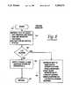
- FIG. 2is a flowchart of a portion of a main loop from the operational program executed by the SCP 17. Only the portion of the loop which is pertinent to an understanding of the present invention is shown and described in detail. In particular, this portion begins at block 111, where the SCP checks the LIDSW signal (FIG. 1) in order to determine the state of the lid switch 68 and thus whether the lid is open. If the lid is open, then at block 112 the SCP checks an internal flag to determine whether the backlight is presently supposed to be on, and if so then the SCP turns on the backlight at block 113 and then continues with the main loop. On the other hand, if it is determined at block 112 that the backlight is not supposed to be on, then block 113 is skipped and the main loop continues.
- the SCPchecks the LIDSW signal (FIG. 1) in order to determine the state of the lid switch 68 and thus whether the lid is open. If the lid is open, then at block 112 the SCP checks an internal flag to determine whether the backlight is
- controlproceeds to block 121, where a check is made to determine what is to happen when the lid is closed.
- the useris allowed to configure the system set-up information to specify that a lid close is to (1) place the system in the suspend mode, (2) turn off the backlight without stopping the system from operating, or (3) produce an audible beep and turn off the backlight without stopping system operation.
- the controlproceeds to block 122, where the SCP sets a suspend request bit in a PMI byte.
- the PMI byteis a byte (8 bits) which is sent on request to the main processor in order to inform the main processor of the reason why the SCP generated a PMI interrupt. Then, also in block 122, the SCP produces a signal on output line 74 (FIG. 1) in order to produce an external PMI to the main processor, which is handled in a manner described later.
- the SCPcould set a flag in block 122 which causes an entirely different portion of the SCP program to actually generate the PMI interrupt upon noting that the flag has been set.
- controlproceeds to block 123, where a check is made to see if an audible beep is to be produced when the lid is closed. If so, then the beep is produced at block 124. In either case, control proceeds to block 125, where the SCP turns off the backlight and clear the backlight flag. From blocks 122 and 125, execution of the main loop continues.
- An event which can interrupt the SCP from the main routine shown in FIG. 2occurs when the main processor sends a command to the SCP.
- the loading of this command into an SCP interface register 81 by the main processorautomatically generates an interrupt to the SCP.
- the interrupt routine which handles the commandsis shown in the flowchart of FIG. 3.
- the command handler of FIG. 3is capable of handling a number of commands, only two of which are pertinent to the present invention and are depicted in FIG. 3.
- executionbegins at block 131, and at 132 the SCP examines the command from the main processor. The SCP then attempts to identify the particular command so that it can be handled.
- controlcan eventually proceed to block 133, where the SCP checks to see if the command is instructing it to identify why the SCP generated an external PMI interrupt to the main processor. If this is the command sent by the main processor, then control proceeds to block 134, where the SCP checks to see whether its ENABLE output is active and the LED signal from the hard drive 23 is simultaneous inactive, and if so proceeds to block 136, where it sets a bit in the PMI byte to identify this condition and then deactuates its ENABLE output. Then, or if it was determined at block 134 that the signals do not have the specified states, control proceeds to block 137, where the SCP passes the PMI byte to the main processor 11 through the registers 81. Control then proceeds to block 138, where the SCP exits the interrupt handler of FIG. 3 and returns to the point in its main program at which it was interrupted.
- FIG. 4is a flowchart of pertinent portions of the special interrupt handling routine executed by the main processor 11 when a PMI interrupt occurs.
- a PMI from any sourcecauses the hardware of the processor 311 to automatically save its state in the portion 40 of the main memory 24, as shown at 146 in FIG. 4.
- the processorautomatically begins execution of the PMI handler routine (which is located at a predetermined point in the portion 40 of the memory 24).
- the first thing the PMI handler doesis to check the resume flag 44 (FIG. 1) in the processor 11 in order to see whether the processor 11 is in the process of resuming from a suspend state. If a resume is in progress, then at block 148 control is transferred to a resume handler, which will be discussed later.
- controlproceeds to block 149, where the processor sets up a special stack for use by the PMI handler, and unlocks configuration registers so that they can be altered, such as the control register 32 which can be used to change the speed of the clock. Then, the processor changes the register 32 in order to force the CPU to run at its fastest clock speed, so that the PMI routine will execute as fast as possible.
- the processorthen proceeds to deal with various possible sources of the PMI, one of which is of interest and is shown at blocks 151 and 152.
- block 151checks to see if the PMI was generated as a result of a signal on the line 38 from the SCP, and if so proceeds to block 152, where an external PMI handler routine is shown in FIG. 5 and is called. The external PMI handler routine will be described later.
- FIG. 5is a flowchart of the external PMI handler routine called by block 152 in FIG. 4.
- executionbegins at block 156, and at block 157 the main processor sends a command to the SCP asking it to identify the reason for the external PMI interrupt.
- the SCPreturns the PMI byte (see blocks 133-134 and 136-137 in FIG. 3).
- the main processorchecks the PMI byte to see if the SCP has initiated a request for suspend mode in response to closing of the lid. If so, then at block 159 the main processor checks to see if the hard disk drive is busy. If it is not, then at block 160 the main processor calls the suspend handler routine, which is described later.
- the main processorproceeds from block 159 to block 161, where it sends a command to the SCP which instructs the SCP to actuate its ENABLE output (see blocks 139-140 in FIG. 3). From blocks 160 and 161, execution proceeds to block 162. Execution can also proceed directly to block 162 from block 158 if it is determined at block 158 that the external PMI interrupt was not caused by closing of the lid.
- the main processorchecks the PMI byte from the SCP to see if the LED signal from the hard disk drive 23 produced the PMI interrupt through the gates 72 and 73. If so, then at block 163 the main processor checks to see whether it has been waiting for the hard disk drive to finish an operation so that it can enter suspend mode or so that it can enter another mode which is called standby and which is not pertinent to the subject matter of the present invention. If the system is to enter standby mode, then at block 164 the processor turns off the hard disk drive motor, and enters the standby mode. Otherwise, at block 166, the processor calls the suspend handler in order to enter the suspend mode. In either case, when the standby or suspend mode is eventually terminated, control proceeds to block 167, where a return is made to the routine of FIG. 4.
- FIG. 6is a flowchart of the suspend handler routine. Execution begins at block 168, and at block 169 the main processor saves the states of various peripherals such as the hard disk drive 23 and video controller 19. The main processor also turns off power to certain peripherals. Then, the main processor sends a command to the SCP which instructs it to send its state to the main processor, and the main processor accepts and stores the contents of the RAM 79 and all registers of the SCP. Then, the main processor sets the refresh control circuit 33 to carry out a refresh of the main memory 24 at a very slow rate, and instructs the power control circuit 12 to turn off SYSVCC power, which is the power for most system components.
- SYSVCC powerwhich is the power for most system components.
- the main processoruses register 77 to toggle the flip-flop 101, which in turn enables the one-shot 96 so that a signal from lid switch 68 due to opening or closing of the lid will initiate a resume.
- the main processorthen executes a special instruction which stops its own clock and which places it in the suspend mode, where power consumption is very low.
- the main processor 11exits the suspend mode when the resume control circuit 41 receives a signal on line 42 or 43 and produces a resume reset, the resume reset setting the resume flag 44.
- Any system resetincluding the resume reset, causes the main processor 11 to execute a special reset handler routine which is stored at a predetermined location in the flash RAM 28 and which is shown in FIG. 7. Execution of this routine begins at block 171, and at block 172 the main processor uses the register 77 to toggle the flip flop 101 and thus disable the one-shot 96 so that, if the lid is opened or closed during normal operation, a further reset does not occur.
- the main processorthen causes the power control circuit 12 to turn on SYSVCC power, and then configures itself and the SCP for normal operation based on set-up data specified by the user in a conventional manner. Then, at block 173, the processor checks the resume flag 44 in order to see whether it is set. If it is not set, then the reset was a regular reset rather than a resume reset, and at block 174 the processor starts the resident operating system. On the other hand, if the resume flag 44 is set to indicate that a resume reset occurred, then at block 176 the processor uses software to produce a PMI interrupt in order to force entry to the PMI handler routine of FIG. 4. In FIG. 4, the resume flag is again checked at 147 and will be found to be set, so that control proceeds to block 148 where a branch is made to the resume handler routine.
- the resume handler routineis shown in FIG. 8. Execution of the resume handler routine begins at block 181, and at block 182 the main processor sends a command to the SCP indicating that the state of the SCP is to be restored, and then sends to the SCP the contents of the SCP RAM and registers which were previously stored at block 169 of FIG. 6. Then, the main processor instructs the SCP to check the state of the lid switch 68 and advise the main processor 11 of the state of the switch. Based on the information from the SCP, the main processor determines at block 183 whether the lid is closed. If it is found that the lid is closed, then the system is to be returned to suspend mode, and so at block 184 the system carries out steps similar to those shown at block 169 in FIG. 6 in order to return the system to suspend mode.
- the main processor 11proceeds from block 183 to block 186 and continues with the process of resuming from suspend mode, in particular by supplying power to and restoring the state of the various peripheral devices of the system. Then, at block 187, the processor executes a return, which effectively returns control to the point at which the suspend handler was called when the system was originally suspended, for example one of the blocks 160 or 166 in FIG. 5. Control then proceeds from that point, and will ultimately return to blocks 153 and 154 of FIG. 4, where the state of the processor will be restored so that the interrupted application program resumes operation from the point at which it was interrupted and as if it had not been interrupted.
- the hard disk drive 23When the hard disk drive 23 finishes what it is doing, it deactuates its LED output, which causes the AND gate 72 to produce an output signal indicating that the hard drive is not busy (HDNB), which passes through the OR gate 73 and causes the PMI generator 36 to generate a further PMI interrupt, which causes another entry to the routine of FIG. 4 and a call at block 152 to the routine of FIG. 5.
- HDNBhard drive is not busy
- the main processorwill recognize from the PMI byte that the SCP generated the PMI because the hard disk drive is no longer busy, and thus the suspend mode (which was not entered at blocks 159-160) can now be entered. Therefore, the main processor will proceed through block 163 to block 166, where the suspend handler of FIG. 6 is called.
- the suspend handler of FIG. 6has already been described, and concludes by placing the main processor 11 in a low power mode in which its clock is turned off and program execution is halted.
- the processorremains in this mode until an event occurs which is intended to cause it to resume operation.
- the lid switch 68will, through the signal processing circuit 13, cause the resume control circuit 41 to produce a resume reset, which in turn causes the processor 11 to begin executing the reset handler routine of FIG. 7.
- the processorwill proceed through blocks 172 and 173 to block 176, where it generates a software PMI to effect reentry to the PMI handler routine of FIG. 4. It will be determined at block 147 that the resume flag 44 (FIG.
- the systemexited suspend mode in response to a resume reset produced by opening the lid.
- Events other than opening the lidcan also produce a resume reset.
- the modem ring indicator signal MDMRI on line 43will cause the resume control circuit 41 to produce a resume reset.
- This resume resetwill be handled in precisely the same manner as described in the foregoing example, except that when block 183 in FIG. 8 is reached, the system will find that the lid is still closed. Therefore, control will proceed to block 184, where the main processor 11 will return to the suspend mode in order to wait for another resume reset caused by subsequent opening of the lid.
Landscapes
- Engineering & Computer Science (AREA)
- Theoretical Computer Science (AREA)
- Physics & Mathematics (AREA)
- General Engineering & Computer Science (AREA)
- General Physics & Mathematics (AREA)
- Power Sources (AREA)
Abstract
Description
Claims (15)
Priority Applications (11)
| Application Number | Priority Date | Filing Date | Title |
|---|---|---|---|
| US07/865,048US5303171A (en) | 1992-04-03 | 1992-04-03 | System suspend on lid close and system resume on lid open |
| JP50025493AJP3701965B2 (en) | 1991-05-17 | 1992-05-15 | Protection mode Microprocessor and hard disk suspend / resume function and idle mode implementation |
| CA002514793ACA2514793C (en) | 1991-05-17 | 1992-05-15 | Computer system suspend on lid close and system resume on lid open |
| EP92912984AEP0584257B1 (en) | 1991-05-17 | 1992-05-15 | Power management capability for a microprocessor having backward compatibility |
| PCT/US1992/004169WO1992021081A1 (en) | 1991-05-17 | 1992-05-15 | Suspend/resume capability for a protected mode microprocessor and hard disk, and idle mode implementation |
| DE69233393TDE69233393T2 (en) | 1991-05-17 | 1992-05-15 | PERFORMANCE MANAGEMENT FUNCTION FOR A BACKWARD COMPATIBLE MICROPROCESSOR |
| EP03019100AEP1413946A3 (en) | 1991-05-17 | 1992-05-15 | Computer system having a reduced power control circuit |
| CA002102421ACA2102421C (en) | 1991-05-17 | 1992-05-15 | Suspend/resume capability for a protected mode microprocessor and hard disk, and idle mode implementation |
| JP2003064174AJP2004005466A (en) | 1991-05-17 | 2003-02-03 | Device and method for attaining interruption, resuming function and idle mode for protective mode microprocessor and hard disk |
| JP2005151313AJP3855172B2 (en) | 1991-05-17 | 2005-05-24 | Method of operating a system including a processor, storage device and peripheral device |
| JP2005296733AJP3904026B2 (en) | 1991-05-17 | 2005-10-11 | Protection mode Microprocessor and hard disk suspend / resume function and idle mode implementation |
Applications Claiming Priority (1)
| Application Number | Priority Date | Filing Date | Title |
|---|---|---|---|
| US07/865,048US5303171A (en) | 1992-04-03 | 1992-04-03 | System suspend on lid close and system resume on lid open |
Publications (1)
| Publication Number | Publication Date |
|---|---|
| US5303171Atrue US5303171A (en) | 1994-04-12 |
Family
ID=25344604
Family Applications (1)
| Application Number | Title | Priority Date | Filing Date |
|---|---|---|---|
| US07/865,048Expired - LifetimeUS5303171A (en) | 1991-05-17 | 1992-04-03 | System suspend on lid close and system resume on lid open |
Country Status (1)
| Country | Link |
|---|---|
| US (1) | US5303171A (en) |
Cited By (50)
| Publication number | Priority date | Publication date | Assignee | Title |
|---|---|---|---|---|
| US5634137A (en)* | 1995-01-17 | 1997-05-27 | International Business Machines Corporation | Method and apparatus for updating system configuration based on open/closed state of computer housing cover |
| US5692197A (en)* | 1995-03-31 | 1997-11-25 | Sun Microsystems, Inc. | Method and apparatus for reducing power consumption in a computer network without sacrificing performance |
| US5721930A (en)* | 1991-07-16 | 1998-02-24 | Canon Kabushiki Kaisha | Electronic apparatus with component operating state control |
| US5768605A (en)* | 1994-03-16 | 1998-06-16 | Itel Corporation | Method and apparatus for power management of a PCMCIA card |
| US5845134A (en)* | 1992-10-29 | 1998-12-01 | Kabushiki Kaisha Toshiba | Suspend/resume control method and system |
| US5926404A (en)* | 1995-05-23 | 1999-07-20 | Dell Usa, L.P. | Computer system with unattended operation power-saving suspend mode |
| US6044473A (en)* | 1997-03-25 | 2000-03-28 | Samsung Electronics Co., Ltd. | Portable computer having a switch for changing a power-controlling mode |
| US6065121A (en)* | 1998-03-31 | 2000-05-16 | Compaq Computer Corporation | Control of computer system wake/sleep transitions |
| US6182187B1 (en)* | 1993-04-07 | 2001-01-30 | Compaq Computer Corporation | System ROM including a flash EPROM and a ROM for storing primary boot code replacing a block flash EPROM |
| US6243819B1 (en) | 1997-04-15 | 2001-06-05 | Samsung Electronics Co., Ltd. | Lid switch in portable computers and the power management system using the same |
| US6282666B1 (en)* | 1999-02-26 | 2001-08-28 | Agere Systems Guardian Corp. | Computer peripheral device having the capability to wake up from a cold state with information stored before cold powerdown |
| US6470358B1 (en)* | 1999-01-22 | 2002-10-22 | Siemens Information And Communication Networks, Inc. | Remote synchronization with intelligent power management |
| EP1229510A3 (en)* | 1999-12-27 | 2002-11-20 | Matsushita Electric Industrial Co., Ltd. | Liquid crystal display apparatus and method for driving the same by performing a transition from an initial state to a display state |
| US6578099B1 (en) | 2000-01-04 | 2003-06-10 | Dell Usa, L.P. | Method and computer system for safely hot-plugging adapter cards |
| US20040061997A1 (en)* | 2002-09-30 | 2004-04-01 | Skinner David N. | Light-emitting lock device control element and electronic device including the same |
| US6757838B1 (en) | 2000-10-13 | 2004-06-29 | Hewlett-Packard Development Company, L.P. | Hardware independent implementation of computer system BIOS recovery |
| US6766461B1 (en)* | 1999-11-30 | 2004-07-20 | Kabushiki Kaisha Toshiba | Status switching method of an information apparatus to ensure an operating status when the apparatus is liable to receive vibration or shock |
| US20040250144A1 (en)* | 2003-06-07 | 2004-12-09 | Samsung Electronics Co., Ltd. | Portable computer power control apparatus and method |
| US20050057450A1 (en)* | 2003-09-02 | 2005-03-17 | Jeong Jae-Seok | Method for controlling address power on plasma display panel and apparatus thereof |
| US20050068311A1 (en)* | 2003-09-30 | 2005-03-31 | Fletcher Terry M. | Switching display update properties upon detecting a power management event |
| US20050114641A1 (en)* | 2003-11-21 | 2005-05-26 | Dell Products L.P. | Information handling system including standby/wakeup feature dependent on sensed conditions |
| US20050156922A1 (en)* | 2004-01-17 | 2005-07-21 | Samsung Electronics Co., Ltd. | Portable computer and controlling method thereof |
| US20050170893A1 (en)* | 2002-07-03 | 2005-08-04 | Muir Robert L. | Gaming machine power fail enhancement |
| US20050278557A1 (en)* | 2004-06-11 | 2005-12-15 | Lenovo (Singapore) Pte. Ltd. | Portable electronic apparatus having an openable lid, program product and method of controlling portable electronic apparatus |
| US20060230294A1 (en)* | 2005-04-08 | 2006-10-12 | Dell Products L.P. | Method and system for determining if an information handling system is operating within a carrying case |
| US20070085822A1 (en)* | 2005-10-13 | 2007-04-19 | Isaac Lagnado | Wireless transmitter enabling/disabling system |
| US20070103135A1 (en)* | 2005-11-07 | 2007-05-10 | Nec Electronics Corporation | Power supply apparatus with discharging switching element operated by one-shot pulse signal |
| US20070130378A1 (en)* | 2005-10-27 | 2007-06-07 | Lin Richard S | Computer protection system and method |
| US20070180282A1 (en)* | 2006-02-02 | 2007-08-02 | Lg Electronics Inc. | Power-saving control apparatus and method for a portable computer |
| US20080005594A1 (en)* | 2006-06-30 | 2008-01-03 | Lenovo (Singapore) Pte. Ltd. | Halt state for protection of hard disk drives in a mobile computing environment |
| US20080313480A1 (en)* | 2007-03-26 | 2008-12-18 | Stmicroelectronics Pvt. Ltd. | Architecture incorporating configurable controller for reducing on chip power leakage |
| US20090023471A1 (en)* | 2007-07-18 | 2009-01-22 | Marcel Manzardo | Method and apparatus for always-on voice client service on mobile computing devices |
| US20090222832A1 (en)* | 2008-02-29 | 2009-09-03 | Dell Products, Lp | System and method of enabling resources within an information handling system |
| US20100033629A1 (en)* | 2008-08-08 | 2010-02-11 | Dell Products, Lp | System, module and method of enabling a video interface within a limited resource enabled information handling system |
| US20100036983A1 (en)* | 2008-08-08 | 2010-02-11 | Dell Products, Lp | Processing module, interface, and information handling system |
| US20100033433A1 (en)* | 2008-08-08 | 2010-02-11 | Dell Products, Lp | Display system and method within a reduced resource information handling system |
| US20100036980A1 (en)* | 2008-08-08 | 2010-02-11 | Dell Products, Lp | Multi-mode processing module and method of use |
| US20100107238A1 (en)* | 2008-10-29 | 2010-04-29 | Dell Products, Lp | Security module and method within an information handling system |
| US20100115050A1 (en)* | 2008-10-30 | 2010-05-06 | Dell Products, Lp | System and method of polling with an information handling system |
| US20100115303A1 (en)* | 2008-10-30 | 2010-05-06 | Dell Products, Lp | System and method of utilizing resources within an information handling system |
| US20100115314A1 (en)* | 2008-10-31 | 2010-05-06 | Dell Products, Lp | Power control for information handling system having shared resources |
| US20100115313A1 (en)* | 2008-10-31 | 2010-05-06 | Dell Products, Lp | Information handling system with integrated low-power processing resources |
| US20100211950A1 (en)* | 2009-02-19 | 2010-08-19 | International Business Machines Corporation | Automated Termination of Selected Software Applications in Response to System Events |
| US20110185209A1 (en)* | 2010-01-23 | 2011-07-28 | Lenovo (Singapore) Pte. Ltd. | Computer that reduces power consumption while maintaining a specific function |
| US20110292540A1 (en)* | 2010-05-28 | 2011-12-01 | Nicholson John W | Systems and Methods for Protecting Hard Disk Drives |
| US8245062B1 (en)* | 2011-05-26 | 2012-08-14 | Google Inc. | Postponing suspend |
| US20130054855A1 (en)* | 2011-08-25 | 2013-02-28 | Renesas Electronics Corporation | Semiconductor integrated circuit apparatus |
| US20150039132A1 (en)* | 2013-08-01 | 2015-02-05 | Hong Fu Jin Precision Industry (Wuhan) Co., Ltd. | Cover control method and portable computer using same |
| US20160338210A1 (en)* | 2015-05-12 | 2016-11-17 | Hong Fu Jin Precision Industry (Shenzhen) Co., Ltd. | Server |
| US20240288917A1 (en)* | 2023-02-27 | 2024-08-29 | Dell Products L.P. | Disregarding spurious power-on and power-off triggers |
Citations (40)
| Publication number | Priority date | Publication date | Assignee | Title |
|---|---|---|---|---|
| JPS5322345A (en)* | 1976-08-13 | 1978-03-01 | Citizen Watch Co Ltd | Control unit of computer |
| US4294496A (en)* | 1979-08-03 | 1981-10-13 | Gm Research | Portable computer enclosure |
| US4317180A (en)* | 1979-12-26 | 1982-02-23 | Texas Instruments Incorporated | Clocked logic low power standby mode |
| US4381552A (en)* | 1978-12-08 | 1983-04-26 | Motorola Inc. | Stanby mode controller utilizing microprocessor |
| US4458307A (en)* | 1977-09-22 | 1984-07-03 | Burroughs Corporation | Data processor system including data-save controller for protection against loss of volatile memory information during power failure |
| US4461003A (en)* | 1980-06-04 | 1984-07-17 | Nippondenso Co., Ltd. | Circuit arrangement for preventing a microcomputer from malfunctioning |
| US4506323A (en)* | 1982-03-03 | 1985-03-19 | Sperry Corporation | Cache/disk file status indicator with data protection feature |
| US4523295A (en)* | 1982-09-07 | 1985-06-11 | Zenith Electronics Corporation | Power loss compensation for programmable memory control system |
| US4564751A (en)* | 1985-03-26 | 1986-01-14 | The Legacy Group Research And Development Limited Partnership | Wrap-around auxiliary keyboard |
| US4626986A (en)* | 1980-12-29 | 1986-12-02 | Fujitsu Limited | Processor having plural initial loading programs for loading different operating systems |
| US4646307A (en)* | 1983-06-22 | 1987-02-24 | Sharp Kabushiki Kaisha | Memory contents confirmation |
| US4658352A (en)* | 1983-06-02 | 1987-04-14 | Pioneer Electronic Corporation | Computer system with a back-up power supply |
| US4674089A (en)* | 1985-04-16 | 1987-06-16 | Intel Corporation | In-circuit emulator |
| US4689761A (en)* | 1984-08-14 | 1987-08-25 | Metaphor Computer Systems | Multiple independent input peripherals |
| US4694393A (en)* | 1983-06-14 | 1987-09-15 | Sharp Kabushiki Kaisha | Peripheral unit for a microprocessor system |
| US4698748A (en)* | 1983-10-07 | 1987-10-06 | Essex Group, Inc. | Power-conserving control system for turning-off the power and the clocking for data transactions upon certain system inactivity |
| US4757505A (en)* | 1986-04-30 | 1988-07-12 | Elgar Electronics Corp. | Computer power system |
| US4763333A (en)* | 1986-08-08 | 1988-08-09 | Universal Vectors Corporation | Work-saving system for preventing loss in a computer due to power interruption |
| US4782468A (en)* | 1986-08-05 | 1988-11-01 | Bally Manufacturing Corporation | Line power failure scheme for a gaming device |
| US4823292A (en)* | 1986-08-18 | 1989-04-18 | U.S. Philips Corporation | Data processing apparatus with energy saving clocking device |
| US4839837A (en)* | 1986-06-04 | 1989-06-13 | Chang Bo E | Three layered laptop computer |
| US4868832A (en)* | 1986-04-30 | 1989-09-19 | Marrington S Paul | Computer power system |
| US4870570A (en)* | 1983-01-24 | 1989-09-26 | Sharp Kabushiki Kaisha | Control system for multi-processor |
| US4907150A (en)* | 1986-01-17 | 1990-03-06 | International Business Machines Corporation | Apparatus and method for suspending and resuming software applications on a computer |
| US4933785A (en)* | 1988-03-01 | 1990-06-12 | Prairietek Corporation | Disk drive apparatus using dynamic loading/unloading |
| US4945335A (en)* | 1988-10-06 | 1990-07-31 | Pioneer Electronic Corporation | Electronic unit operable in conjunction with body unit |
| US4980836A (en)* | 1988-10-14 | 1990-12-25 | Compaq Computer Corporation | Apparatus for reducing computer system power consumption |
| US4991129A (en)* | 1989-07-25 | 1991-02-05 | Areal Technology, Inc. | Dual mode actuator for disk drive useful with a portable computer |
| US5021983A (en)* | 1989-11-13 | 1991-06-04 | Chips And Technologies, Inc. | Suspend/resume apparatus and method for reducing power consumption in battery powered computers |
| US5027294A (en)* | 1989-01-27 | 1991-06-25 | Zenith Data Systems Corporation | Method and apparatus for battery-power management using load-compensation monitoring of battery discharge |
| US5027273A (en)* | 1985-04-10 | 1991-06-25 | Microsoft Corporation | Method and operating system for executing programs in a multi-mode microprocessor |
| US5068652A (en)* | 1989-06-23 | 1991-11-26 | Kabushiki Kaisha Toshiba | Personal computer having condition indicator |
| US5077551A (en)* | 1988-11-30 | 1991-12-31 | Kabushiki Kaisha Toshiba | Display panel open/closed detection mechanism, and portable electronic apparatus using the same |
| US5129091A (en)* | 1988-05-06 | 1992-07-07 | Toppan Printing Co., Ltd. | Integrated-circuit card with active mode and low power mode |
| US5142684A (en)* | 1989-06-23 | 1992-08-25 | Hand Held Products, Inc. | Power conservation in microprocessor controlled devices |
| US5155840A (en)* | 1990-03-16 | 1992-10-13 | Nec Corporation | Single-chip mircocomputer with clock-signal switching function which can disable a high-speed oscillator to reduce power consumption |
| US5163153A (en)* | 1989-06-12 | 1992-11-10 | Grid Systems Corporation | Low-power, standby mode computer |
| US5167024A (en)* | 1989-09-08 | 1992-11-24 | Apple Computer, Inc. | Power management for a laptop computer with slow and sleep modes |
| US5175845A (en)* | 1988-12-09 | 1992-12-29 | Dallas Semiconductor Corp. | Integrated circuit with watchdog timer and sleep control logic which places IC and watchdog timer into sleep mode |
| US5175853A (en)* | 1990-10-09 | 1992-12-29 | Intel Corporation | Transparent system interrupt |
- 1992
- 1992-04-03USUS07/865,048patent/US5303171A/ennot_activeExpired - Lifetime
Patent Citations (42)
| Publication number | Priority date | Publication date | Assignee | Title |
|---|---|---|---|---|
| JPS5322345A (en)* | 1976-08-13 | 1978-03-01 | Citizen Watch Co Ltd | Control unit of computer |
| US4458307A (en)* | 1977-09-22 | 1984-07-03 | Burroughs Corporation | Data processor system including data-save controller for protection against loss of volatile memory information during power failure |
| US4381552A (en)* | 1978-12-08 | 1983-04-26 | Motorola Inc. | Stanby mode controller utilizing microprocessor |
| US4294496A (en)* | 1979-08-03 | 1981-10-13 | Gm Research | Portable computer enclosure |
| US4317180A (en)* | 1979-12-26 | 1982-02-23 | Texas Instruments Incorporated | Clocked logic low power standby mode |
| US4461003A (en)* | 1980-06-04 | 1984-07-17 | Nippondenso Co., Ltd. | Circuit arrangement for preventing a microcomputer from malfunctioning |
| US4626986A (en)* | 1980-12-29 | 1986-12-02 | Fujitsu Limited | Processor having plural initial loading programs for loading different operating systems |
| US4506323A (en)* | 1982-03-03 | 1985-03-19 | Sperry Corporation | Cache/disk file status indicator with data protection feature |
| US4523295A (en)* | 1982-09-07 | 1985-06-11 | Zenith Electronics Corporation | Power loss compensation for programmable memory control system |
| US4870570A (en)* | 1983-01-24 | 1989-09-26 | Sharp Kabushiki Kaisha | Control system for multi-processor |
| US4658352A (en)* | 1983-06-02 | 1987-04-14 | Pioneer Electronic Corporation | Computer system with a back-up power supply |
| US4694393A (en)* | 1983-06-14 | 1987-09-15 | Sharp Kabushiki Kaisha | Peripheral unit for a microprocessor system |
| US4646307A (en)* | 1983-06-22 | 1987-02-24 | Sharp Kabushiki Kaisha | Memory contents confirmation |
| US4698748A (en)* | 1983-10-07 | 1987-10-06 | Essex Group, Inc. | Power-conserving control system for turning-off the power and the clocking for data transactions upon certain system inactivity |
| US4689761A (en)* | 1984-08-14 | 1987-08-25 | Metaphor Computer Systems | Multiple independent input peripherals |
| US4564751A (en)* | 1985-03-26 | 1986-01-14 | The Legacy Group Research And Development Limited Partnership | Wrap-around auxiliary keyboard |
| US5027273A (en)* | 1985-04-10 | 1991-06-25 | Microsoft Corporation | Method and operating system for executing programs in a multi-mode microprocessor |
| US4674089A (en)* | 1985-04-16 | 1987-06-16 | Intel Corporation | In-circuit emulator |
| US4907150A (en)* | 1986-01-17 | 1990-03-06 | International Business Machines Corporation | Apparatus and method for suspending and resuming software applications on a computer |
| US4757505A (en)* | 1986-04-30 | 1988-07-12 | Elgar Electronics Corp. | Computer power system |
| US4868832A (en)* | 1986-04-30 | 1989-09-19 | Marrington S Paul | Computer power system |
| US4839837A (en)* | 1986-06-04 | 1989-06-13 | Chang Bo E | Three layered laptop computer |
| US4782468A (en)* | 1986-08-05 | 1988-11-01 | Bally Manufacturing Corporation | Line power failure scheme for a gaming device |
| US4763333B1 (en)* | 1986-08-08 | 1990-09-04 | Univ Vectors Corp | |
| US4763333A (en)* | 1986-08-08 | 1988-08-09 | Universal Vectors Corporation | Work-saving system for preventing loss in a computer due to power interruption |
| US4823292A (en)* | 1986-08-18 | 1989-04-18 | U.S. Philips Corporation | Data processing apparatus with energy saving clocking device |
| US4933785A (en)* | 1988-03-01 | 1990-06-12 | Prairietek Corporation | Disk drive apparatus using dynamic loading/unloading |
| US5129091A (en)* | 1988-05-06 | 1992-07-07 | Toppan Printing Co., Ltd. | Integrated-circuit card with active mode and low power mode |
| US4945335A (en)* | 1988-10-06 | 1990-07-31 | Pioneer Electronic Corporation | Electronic unit operable in conjunction with body unit |
| US4980836A (en)* | 1988-10-14 | 1990-12-25 | Compaq Computer Corporation | Apparatus for reducing computer system power consumption |
| US5077551A (en)* | 1988-11-30 | 1991-12-31 | Kabushiki Kaisha Toshiba | Display panel open/closed detection mechanism, and portable electronic apparatus using the same |
| US5175845A (en)* | 1988-12-09 | 1992-12-29 | Dallas Semiconductor Corp. | Integrated circuit with watchdog timer and sleep control logic which places IC and watchdog timer into sleep mode |
| US5027294A (en)* | 1989-01-27 | 1991-06-25 | Zenith Data Systems Corporation | Method and apparatus for battery-power management using load-compensation monitoring of battery discharge |
| US5163153A (en)* | 1989-06-12 | 1992-11-10 | Grid Systems Corporation | Low-power, standby mode computer |
| US5068652A (en)* | 1989-06-23 | 1991-11-26 | Kabushiki Kaisha Toshiba | Personal computer having condition indicator |
| US5142684A (en)* | 1989-06-23 | 1992-08-25 | Hand Held Products, Inc. | Power conservation in microprocessor controlled devices |
| US4991129A (en)* | 1989-07-25 | 1991-02-05 | Areal Technology, Inc. | Dual mode actuator for disk drive useful with a portable computer |
| US5167024A (en)* | 1989-09-08 | 1992-11-24 | Apple Computer, Inc. | Power management for a laptop computer with slow and sleep modes |
| US5021983A (en)* | 1989-11-13 | 1991-06-04 | Chips And Technologies, Inc. | Suspend/resume apparatus and method for reducing power consumption in battery powered computers |
| US5021983B1 (en)* | 1989-11-13 | 1996-05-28 | Chips & Technologies Inc | Suspend/resume apparatus and method for reducing power consumption in battery powered computers |
| US5155840A (en)* | 1990-03-16 | 1992-10-13 | Nec Corporation | Single-chip mircocomputer with clock-signal switching function which can disable a high-speed oscillator to reduce power consumption |
| US5175853A (en)* | 1990-10-09 | 1992-12-29 | Intel Corporation | Transparent system interrupt |
Non-Patent Citations (8)
| Title |
|---|
| Clements, Alan; "Microprocessor Systems Design", 1987, Title pages and pp. 117, 246, 247, 353, 354, PWS-Kent Publishing Company, Boston. |
| Clements, Alan; Microprocessor Systems Design , 1987, Title pages and pp. 117, 246, 247, 353, 354, PWS Kent Publishing Company, Boston.* |
| IBM System/360 Principles of Operation, Eighth Edition (Sep., 1968) Title Pages and pp. 68 83.* |
| IBM System/360 Principles of Operation, Eighth Edition (Sep., 1968) Title Pages and pp. 68-83. |
| Microsoft, MS DOS, User s Guide, 1986, Title Pages and p. 245.* |
| Microsoft, MS-DOS, User's Guide, 1986, Title Pages and p. 245. |
| Toshiba T1600 Portable Personal Computer User s Manual, 2nd edition Apr. 1987, pp. 2 1 to 2 3 and 2 8 to 2 11.* |
| Toshiba T1600 Portable Personal Computer User's Manual, 2nd edition Apr. 1987, pp. 2-1 to 2-3 and 2-8 to 2-11. |
Cited By (95)
| Publication number | Priority date | Publication date | Assignee | Title |
|---|---|---|---|---|
| US5721930A (en)* | 1991-07-16 | 1998-02-24 | Canon Kabushiki Kaisha | Electronic apparatus with component operating state control |
| US5845134A (en)* | 1992-10-29 | 1998-12-01 | Kabushiki Kaisha Toshiba | Suspend/resume control method and system |
| US6182187B1 (en)* | 1993-04-07 | 2001-01-30 | Compaq Computer Corporation | System ROM including a flash EPROM and a ROM for storing primary boot code replacing a block flash EPROM |
| US5768605A (en)* | 1994-03-16 | 1998-06-16 | Itel Corporation | Method and apparatus for power management of a PCMCIA card |
| US5634137A (en)* | 1995-01-17 | 1997-05-27 | International Business Machines Corporation | Method and apparatus for updating system configuration based on open/closed state of computer housing cover |
| US5692197A (en)* | 1995-03-31 | 1997-11-25 | Sun Microsystems, Inc. | Method and apparatus for reducing power consumption in a computer network without sacrificing performance |
| US5926404A (en)* | 1995-05-23 | 1999-07-20 | Dell Usa, L.P. | Computer system with unattended operation power-saving suspend mode |
| US6044473A (en)* | 1997-03-25 | 2000-03-28 | Samsung Electronics Co., Ltd. | Portable computer having a switch for changing a power-controlling mode |
| US6243819B1 (en) | 1997-04-15 | 2001-06-05 | Samsung Electronics Co., Ltd. | Lid switch in portable computers and the power management system using the same |
| US6065121A (en)* | 1998-03-31 | 2000-05-16 | Compaq Computer Corporation | Control of computer system wake/sleep transitions |
| US6470358B1 (en)* | 1999-01-22 | 2002-10-22 | Siemens Information And Communication Networks, Inc. | Remote synchronization with intelligent power management |
| US6282666B1 (en)* | 1999-02-26 | 2001-08-28 | Agere Systems Guardian Corp. | Computer peripheral device having the capability to wake up from a cold state with information stored before cold powerdown |
| US6766461B1 (en)* | 1999-11-30 | 2004-07-20 | Kabushiki Kaisha Toshiba | Status switching method of an information apparatus to ensure an operating status when the apparatus is liable to receive vibration or shock |
| EP1229510A3 (en)* | 1999-12-27 | 2002-11-20 | Matsushita Electric Industrial Co., Ltd. | Liquid crystal display apparatus and method for driving the same by performing a transition from an initial state to a display state |
| US6578099B1 (en) | 2000-01-04 | 2003-06-10 | Dell Usa, L.P. | Method and computer system for safely hot-plugging adapter cards |
| US6757838B1 (en) | 2000-10-13 | 2004-06-29 | Hewlett-Packard Development Company, L.P. | Hardware independent implementation of computer system BIOS recovery |
| US20100093427A1 (en)* | 2002-07-03 | 2010-04-15 | Aristocrat Technologies Australia Pty Limited | Gaming machine power fail enhancement |
| US8657669B2 (en) | 2002-07-03 | 2014-02-25 | Aristocrat Technologies Australia Pty Limited | Gaming machine power fail enhancement |
| US9147311B2 (en) | 2002-07-03 | 2015-09-29 | Aristocrat Technologies Australia Pty Limited | Gaming machine power fail enhancement |
| US20050170893A1 (en)* | 2002-07-03 | 2005-08-04 | Muir Robert L. | Gaming machine power fail enhancement |
| US8241109B2 (en)* | 2002-07-03 | 2012-08-14 | Aristocrat Technologies Australia Pty Limited | Gaming machine power fail enhancement |
| US20040061997A1 (en)* | 2002-09-30 | 2004-04-01 | Skinner David N. | Light-emitting lock device control element and electronic device including the same |
| US6717804B1 (en)* | 2002-09-30 | 2004-04-06 | Hewlett-Packard Development Company, L.P. | Light-emitting lock device control element and electronic device including the same |
| US7370218B2 (en) | 2003-06-07 | 2008-05-06 | Samsung Electronics Co., Ltd. | Portable computer power control apparatus and method |
| US20040250144A1 (en)* | 2003-06-07 | 2004-12-09 | Samsung Electronics Co., Ltd. | Portable computer power control apparatus and method |
| US20050057450A1 (en)* | 2003-09-02 | 2005-03-17 | Jeong Jae-Seok | Method for controlling address power on plasma display panel and apparatus thereof |
| US20050068311A1 (en)* | 2003-09-30 | 2005-03-31 | Fletcher Terry M. | Switching display update properties upon detecting a power management event |
| US8363044B2 (en) | 2003-09-30 | 2013-01-29 | Intel Corporation | Switching display update properties upon detecting a power management event |
| US8860707B2 (en) | 2003-09-30 | 2014-10-14 | Intel Corporation | Switching display update properties upon detecting a power management event |
| US20090160841A1 (en)* | 2003-09-30 | 2009-06-25 | Fletcher Terry M | Switching display update properties upon detecting a power management event |
| US7538762B2 (en)* | 2003-09-30 | 2009-05-26 | Intel Corporation | Switching display update properties upon detecting a power management event |
| US7406612B2 (en)* | 2003-11-21 | 2008-07-29 | Dell Products, L.P. | Information handling system including standby/wakeup feature dependent on sensed conditions |
| US20050114641A1 (en)* | 2003-11-21 | 2005-05-26 | Dell Products L.P. | Information handling system including standby/wakeup feature dependent on sensed conditions |
| US7719528B2 (en)* | 2004-01-17 | 2010-05-18 | Samsung Electronics Co., Ltd. | Portable computer and controlling method thereof |
| US20050156922A1 (en)* | 2004-01-17 | 2005-07-21 | Samsung Electronics Co., Ltd. | Portable computer and controlling method thereof |
| US7480813B2 (en)* | 2004-06-11 | 2009-01-20 | Lenovo (Singapore) Pte., Ltd. | Portable electronic apparatus having a transfer mode for stopping an operating state of a device |
| US20050278557A1 (en)* | 2004-06-11 | 2005-12-15 | Lenovo (Singapore) Pte. Ltd. | Portable electronic apparatus having an openable lid, program product and method of controlling portable electronic apparatus |
| US7366923B2 (en)* | 2005-04-08 | 2008-04-29 | Dell Products L.P. | Method and system for determining if an information handling system is operating within a carrying case |
| US20060230294A1 (en)* | 2005-04-08 | 2006-10-12 | Dell Products L.P. | Method and system for determining if an information handling system is operating within a carrying case |
| US20070085822A1 (en)* | 2005-10-13 | 2007-04-19 | Isaac Lagnado | Wireless transmitter enabling/disabling system |
| US20070130378A1 (en)* | 2005-10-27 | 2007-06-07 | Lin Richard S | Computer protection system and method |
| US8959255B2 (en) | 2005-10-27 | 2015-02-17 | Hewlett-Packard Development Company, L.P. | Computer protection system and method |
| US20070103135A1 (en)* | 2005-11-07 | 2007-05-10 | Nec Electronics Corporation | Power supply apparatus with discharging switching element operated by one-shot pulse signal |
| US20070180282A1 (en)* | 2006-02-02 | 2007-08-02 | Lg Electronics Inc. | Power-saving control apparatus and method for a portable computer |
| US7620830B2 (en)* | 2006-06-30 | 2009-11-17 | Lenovo Singapore Pte. Ltd. | Halt state for protection of hard disk drives in a mobile computing environment |
| US20080005594A1 (en)* | 2006-06-30 | 2008-01-03 | Lenovo (Singapore) Pte. Ltd. | Halt state for protection of hard disk drives in a mobile computing environment |
| US8286012B2 (en) | 2007-03-26 | 2012-10-09 | Stmicroelectronics Pvt. Ltd. | Architecture incorporating configurable controller for reducing on chip power leakage |
| US20080313480A1 (en)* | 2007-03-26 | 2008-12-18 | Stmicroelectronics Pvt. Ltd. | Architecture incorporating configurable controller for reducing on chip power leakage |
| US7953994B2 (en)* | 2007-03-26 | 2011-05-31 | Stmicroelectronics Pvt. Ltd. | Architecture incorporating configurable controller for reducing on chip power leakage |
| US8275411B2 (en) | 2007-07-18 | 2012-09-25 | Siemens Enterprise Communications, Inc. | Method and apparatus for always-on voice client service on mobile computing devices |
| US20090023471A1 (en)* | 2007-07-18 | 2009-01-22 | Marcel Manzardo | Method and apparatus for always-on voice client service on mobile computing devices |
| US20090222832A1 (en)* | 2008-02-29 | 2009-09-03 | Dell Products, Lp | System and method of enabling resources within an information handling system |
| US7921239B2 (en) | 2008-08-08 | 2011-04-05 | Dell Products, Lp | Multi-mode processing module and method of use |
| US20100036980A1 (en)* | 2008-08-08 | 2010-02-11 | Dell Products, Lp | Multi-mode processing module and method of use |
| US20100036983A1 (en)* | 2008-08-08 | 2010-02-11 | Dell Products, Lp | Processing module, interface, and information handling system |
| US20100033433A1 (en)* | 2008-08-08 | 2010-02-11 | Dell Products, Lp | Display system and method within a reduced resource information handling system |
| US20110225326A1 (en)* | 2008-08-08 | 2011-09-15 | Dell Products, Lp | Multi-Mode Processing Module and Method of Use |
| US8520014B2 (en) | 2008-08-08 | 2013-08-27 | Dell Products, Lp | System, module, and method of enabling a video interface within a limited resource enabled information handling system |
| US20100033629A1 (en)* | 2008-08-08 | 2010-02-11 | Dell Products, Lp | System, module and method of enabling a video interface within a limited resource enabled information handling system |
| US8463957B2 (en) | 2008-08-08 | 2013-06-11 | Dell Products, Lp | Enabling access to peripheral resources at a processor |
| US8131904B2 (en)* | 2008-08-08 | 2012-03-06 | Dell Products, Lp | Processing module, interface, and information handling system |
| US8134565B2 (en) | 2008-08-08 | 2012-03-13 | Dell Products, Lp | System, module and method of enabling a video interface within a limited resource enabled information handling system |
| US8255595B2 (en) | 2008-08-08 | 2012-08-28 | Dell Products, Lp | Enabling access to peripheral resources at a processor |
| US8863268B2 (en) | 2008-10-29 | 2014-10-14 | Dell Products, Lp | Security module and method within an information handling system |
| US10516668B2 (en) | 2008-10-29 | 2019-12-24 | Dell Products, Lp | Security module and method within an information handling system |
| US20100107238A1 (en)* | 2008-10-29 | 2010-04-29 | Dell Products, Lp | Security module and method within an information handling system |
| US20100115050A1 (en)* | 2008-10-30 | 2010-05-06 | Dell Products, Lp | System and method of polling with an information handling system |
| US9407694B2 (en) | 2008-10-30 | 2016-08-02 | Dell Products, Lp | System and method of polling with an information handling system |
| US20100115303A1 (en)* | 2008-10-30 | 2010-05-06 | Dell Products, Lp | System and method of utilizing resources within an information handling system |
| US8769328B2 (en) | 2008-10-30 | 2014-07-01 | Dell Products, Lp | System and method of utilizing resources within an information handling system |
| US8370673B2 (en) | 2008-10-30 | 2013-02-05 | Dell Products, Lp | System and method of utilizing resources within an information handling system |
| US10148787B2 (en) | 2008-10-30 | 2018-12-04 | Dell Products, Lp | System and method of polling with an information handling system |
| US8583953B2 (en) | 2008-10-31 | 2013-11-12 | Dell Products, Lp | Power control for information handling system having shared resources |
| US8271817B2 (en) | 2008-10-31 | 2012-09-18 | Dell Products, Lp | Information handling system with processing system, low-power processing system and shared resources |
| US8065540B2 (en) | 2008-10-31 | 2011-11-22 | Dell Products, Lp | Power control for information handling system having shared resources |
| US8037333B2 (en) | 2008-10-31 | 2011-10-11 | Dell Products, Lp | Information handling system with processing system, low-power processing system and shared resources |
| US8799695B2 (en) | 2008-10-31 | 2014-08-05 | Dell Products, Lp | Information handling system with processing system, low-power processing system and shared resources |
| US20100115313A1 (en)* | 2008-10-31 | 2010-05-06 | Dell Products, Lp | Information handling system with integrated low-power processing resources |
| US20100115314A1 (en)* | 2008-10-31 | 2010-05-06 | Dell Products, Lp | Power control for information handling system having shared resources |
| US8255928B2 (en) | 2009-02-19 | 2012-08-28 | International Business Machines Corporation | Automated termination of selected software applications in response system events |
| US20100211950A1 (en)* | 2009-02-19 | 2010-08-19 | International Business Machines Corporation | Automated Termination of Selected Software Applications in Response to System Events |
| US20110185209A1 (en)* | 2010-01-23 | 2011-07-28 | Lenovo (Singapore) Pte. Ltd. | Computer that reduces power consumption while maintaining a specific function |
| US8856572B2 (en)* | 2010-01-23 | 2014-10-07 | Lenovo (Singapore) Pte. Ltd. | Computer that reduces power consumption while maintaining a specific function |
| US20110292540A1 (en)* | 2010-05-28 | 2011-12-01 | Nicholson John W | Systems and Methods for Protecting Hard Disk Drives |
| US10741209B2 (en)* | 2010-05-28 | 2020-08-11 | Lenovo (Singapore) Pte. Ltd. | Systems and methods for protecting hard disk drives |
| US9116704B1 (en) | 2011-05-26 | 2015-08-25 | Google Inc. | Delaying the initiation of transitioning to a lower power mode by placing a computer system into an intermediate power mode between a normal power mode and the lower power mode |
| US8671299B2 (en) | 2011-05-26 | 2014-03-11 | Google Inc. | Delaying the initiation of transitioning to a lower power mode by placing a computer system into an intermediate power mode between a normal power mode and the lower power mode |
| US8245062B1 (en)* | 2011-05-26 | 2012-08-14 | Google Inc. | Postponing suspend |
| US9003217B2 (en)* | 2011-08-25 | 2015-04-07 | Renesas Electronics Corporation | Semiconductor integrated circuit apparatus |
| US20130054855A1 (en)* | 2011-08-25 | 2013-02-28 | Renesas Electronics Corporation | Semiconductor integrated circuit apparatus |
| US20150039132A1 (en)* | 2013-08-01 | 2015-02-05 | Hong Fu Jin Precision Industry (Wuhan) Co., Ltd. | Cover control method and portable computer using same |
| US20160338210A1 (en)* | 2015-05-12 | 2016-11-17 | Hong Fu Jin Precision Industry (Shenzhen) Co., Ltd. | Server |
| US9686881B2 (en)* | 2015-05-12 | 2017-06-20 | Hong Fu Jin Precision Industry (Shenzhen) Co., Ltd. | Server |
| US20240288917A1 (en)* | 2023-02-27 | 2024-08-29 | Dell Products L.P. | Disregarding spurious power-on and power-off triggers |
| US12265434B2 (en)* | 2023-02-27 | 2025-04-01 | Dell Products L.P. | Disregarding spurious power-on and power-off triggers |
Similar Documents
| Publication | Publication Date | Title |
|---|---|---|
| US5303171A (en) | System suspend on lid close and system resume on lid open | |
| US5652890A (en) | Interrupt for a protected mode microprocessor which facilitates transparent entry to and exit from suspend mode | |
| JP3701965B2 (en) | Protection mode Microprocessor and hard disk suspend / resume function and idle mode implementation | |
| US5369771A (en) | Computer with transparent power-saving manipulation of CPU clock | |
| EP0501655B1 (en) | Reducing power consumption in a digital processor | |
| US5446904A (en) | Suspend/resume capability for a protected mode microprocessor | |
| EP0426410B1 (en) | Real-time power conservation for portable computers | |
| US5903765A (en) | Power management system for a computer | |
| US5560024A (en) | Computer power management system | |
| US4851987A (en) | System for reducing processor power consumption by stopping processor clock supply if a desired event does not occur | |
| US5446906A (en) | Method and apparatus for suspending and resuming a keyboard controller | |
| US6193422B1 (en) | Implementation of idle mode in a suspend/resume microprocessor system | |
| JP3213208B2 (en) | Information processing apparatus and control method thereof | |
| US20020095609A1 (en) | Multiprocessor apparatus | |
| JPH04333119A (en) | information processing equipment | |
| JPH07101386B2 (en) | Battery operated computer and its initial setting method | |
| US20100250972A1 (en) | Reversible power transitions in a computing device | |
| US7111182B2 (en) | Thread scheduling mechanisms for processor resource power management | |
| US5771390A (en) | System and method for cascading from a power managed suspend state to a suspend-to-disk state in a computer system | |
| JPH11102238A (en) | Computer system and suspend control method in the system | |
| CA2514793C (en) | Computer system suspend on lid close and system resume on lid open | |
| JPH10149232A (en) | System processing request system for power-off time | |
| JPH0651880A (en) | Information processing equipment |
Legal Events
| Date | Code | Title | Description |
|---|---|---|---|
| AS | Assignment | Owner name:ZENITH DATA SYSTEMS CORPORATION A CORP. OF DELAWA Free format text:ASSIGNMENT OF ASSIGNORS INTEREST.;ASSIGNORS:BELT, STEVEN L.;GRABON, ROBERT J.;PANDYA, CHANDRAKANT H.;AND OTHERS;REEL/FRAME:006141/0198 Effective date:19920518 | |
| STCF | Information on status: patent grant | Free format text:PATENTED CASE | |
| CC | Certificate of correction | ||
| AS | Assignment | Owner name:VANTUS TECHNOLOGIES, INC., ILLINOIS Free format text:ASSIGNMENT OF ASSIGNORS INTEREST;ASSIGNOR:ZENITH DATA SYSTEMS CORPORATIO;REEL/FRAME:007453/0477 Effective date:19950424 | |
| AS | Assignment | Owner name:SUMITOMO BANK OF NEW YORK TRUST COMPANY, NEW YORK Free format text:ASSIGNMENT OF ASSIGNORS INTEREST;ASSIGNOR:VANTUS TECHNOLOGIES, INC.;REEL/FRAME:008442/0095 Effective date:19970325 | |
| FPAY | Fee payment | Year of fee payment:4 | |
| SULP | Surcharge for late payment | ||
| FEPP | Fee payment procedure | Free format text:PAYOR NUMBER ASSIGNED (ORIGINAL EVENT CODE: ASPN); ENTITY STATUS OF PATENT OWNER: LARGE ENTITY | |
| AS | Assignment | Owner name:SUMITOMO BANK, LIMITED, NEW YORK BRANCH, THE, AS C Free format text:TRANSFER OF SECURITY INTEREST;ASSIGNOR:SUMITOMO BANK OF NEW YORK TRUST COMPANY;REEL/FRAME:009756/0202 Effective date:19990108 | |
| AS | Assignment | Owner name:VANTUS TECHNOLOGIES, INC., ILLINOIS Free format text:TERMINATION OF SECURITY INTEREST;ASSIGNOR:SUMITOMO BANK LIMITED, THE;REEL/FRAME:010263/0070 Effective date:19990301 | |
| AS | Assignment | Owner name:NEC CORPORATION, JAPAN Free format text:ASSIGNMENT OF ASSIGNORS INTEREST;ASSIGNOR:VANTUS TECHNOLOGIES, INC.;REEL/FRAME:011007/0792 Effective date:20000223 | |
| FPAY | Fee payment | Year of fee payment:8 | |
| FPAY | Fee payment | Year of fee payment:12 | |
| AS | Assignment | Owner name:VANTUS TECHNOLOGIES, INC., ILLINOIS Free format text:ASSIGNMENT OF ASSIGNORS INTEREST;ASSIGNOR:ZENITH DATA SYSTEMS CORPORATION;REEL/FRAME:027691/0083 Effective date:19950424 |