US5302935A - Renewable gas sensor, renewable gas sensor base and method for renewing a gas sensor - Google Patents
Renewable gas sensor, renewable gas sensor base and method for renewing a gas sensorDownload PDFInfo
- Publication number
- US5302935A US5302935AUS07/987,931US98793192AUS5302935AUS 5302935 AUS5302935 AUS 5302935AUS 98793192 AUS98793192 AUS 98793192AUS 5302935 AUS5302935 AUS 5302935A
- Authority
- US
- United States
- Prior art keywords
- gas sensor
- separator
- electrode array
- heater
- renewable
- Prior art date
- Legal status (The legal status is an assumption and is not a legal conclusion. Google has not performed a legal analysis and makes no representation as to the accuracy of the status listed.)
- Expired - Lifetime
Links
Images

Classifications
- G—PHYSICS
- G01—MEASURING; TESTING
- G01N—INVESTIGATING OR ANALYSING MATERIALS BY DETERMINING THEIR CHEMICAL OR PHYSICAL PROPERTIES
- G01N27/00—Investigating or analysing materials by the use of electric, electrochemical, or magnetic means
- G01N27/02—Investigating or analysing materials by the use of electric, electrochemical, or magnetic means by investigating impedance
- G01N27/04—Investigating or analysing materials by the use of electric, electrochemical, or magnetic means by investigating impedance by investigating resistance
- G01N27/12—Investigating or analysing materials by the use of electric, electrochemical, or magnetic means by investigating impedance by investigating resistance of a solid body in dependence upon absorption of a fluid; of a solid body in dependence upon reaction with a fluid, for detecting components in the fluid
Definitions
- This inventionrelates to gas sensing and particularly relates to a renewable gas sensor, a gas sensor base and a method for renewing a gas sensor.
- a chemiresistor sensing devicegenerally contemplates the use of a power supply transmitting current through a sensor which contains a semiconductor material, such as a metal oxide.
- the semiconductor materialbehaves as a chemiresistor.
- a chemical influencecan be caused by an ambient gas interacting with the semiconductor material and can be monitored by a change in the resistance or conductance of the material by the use of electrodes which transmit the change in conductance to a monitor or detector, such as a voltmeter or ohmmeter.
- a typical chemiresistor sensorhas a resistor layer, such as a heater resistor, an electrical connection to the heater, a support layer, such as an alumina substrate, a conductor layer (often composed of interdigitated electrodes) and a deposited chemical sensing layer, for example tungsten oxide is used in U.S. Pat. No. 4,822,465 to detect sulfide.
- the thickness and manner in which the metal oxide semiconductor material is applied to the sensor electrodesare of importance to the functioning of the sensor, because the depth and microstructure of the metal oxide layer can affect both the selectivity and sensitivity of the tungsten oxide layer to sensed gas.
- the term "sensed gas"is used herein to designate one or more gases which will cause a change in resistivity of a chemiresistor gas sensor.
- Thin film chemiresistor gas sensorshave good response times, but are relatively expensive to produce and are subject to relatively rapid failure when used in an aggressive environment in which the sensor material itself is subject to degradation.
- Chemiresistor sensorshave a further shortcoming that many sensor materials are subject to saturation with sensed gas. Partial saturation may permit continued, but possibly degraded, use; however, irreversible saturation of the sensor material necessitates replacement of the entire gas sensor.
- chemiresistor sensorwhich can use a thin film, is relatively rugged and can be renewed without replacement of the entire gas sensor and a sensor base and a method for renewing a gas sensor.
- a renewable gas sensorwhich has a substantially planar heater.
- a substantially planar separatoris superimposed on the heater.
- the separatoris electrically insulating and thermally conducting.
- An electrode arrayis superimposed on the separator.
- the electrode array and the separatordefine a plurality of juxtaposed sensing sites disposed in electrically conductive relation to the electrode array and in thermally conductive relation to the separator.
- a chemical sensing filmis superimposed on the separator and said electrode array in one of the sensing sites.
- a renewable gas sensor basecomprising a substantially planar heater, a substantially planar separator superimposed on the heater, and an electrode array superimpose on the separator.
- the separatoris electrically insulating and thermally conducting.
- the electrode array and separatordefine a plurality of juxtaposed sensing sites disposed in electrically conductive relation to the electrode array and in thermally conductive relation to the separator. At least one sensing site is capable of receiving a chemical sensing film in superimposition on the separator and the electrode array.
- a method for renewing a gas sensor having an expended chemical sensing film and an unoccupied sensing sitecomprising depositing by a physical film deposition technique an unexpended chemical sensing film in the unoccupied sensing site.
- FIG. 1is a schematic diagram which shows an embodiment of the renewable sensor of the invention incorporated in an electrical circuit.
- FIG. 2is a surface view of the renewable sensor of FIG. 1. Dashed lines indicate the positions of hidden structures.
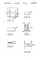
- FIG. 3is a top plan view of the substrate and heater electrodes of the renewable sensor of FIG. 1.
- FIG. 4is a top plan view of the heater of the renewable sensor of FIG. 1.
- FIG. 5is a top plan view of the separator of the renewable sensor of FIG. 1.
- FIG. 6is a top plan view of the electrode array of the renewable sensor of FIG. 1.
- FIG. 7is a top plan view of an expended sensing film and a juxtaposed unexpended sensing film of the renewable sensor of FIG. 1.
- FIG. 8is a top plan view of the conductor array of an alternative embodiment of the renewable sensor of the invention.
- the renewable gas sensor 10 of the inventionis an essentially planar, multilayer structure having a sensor base 12 and one or more chemical sensing films 14 overlaying sensor base 12.
- Sensor base 12has five components 16,18,20,22,24, with a substrate 16 lowermost.
- Sensor elements 14,16,18,20,22,24,are depicted using hidden lines in FIG. 2 and separately in FIGS. 3-7.
- Components 18,20,22,24,are essentially planar layers overlaying substrate 16. It is desirable that each of components 18,20,22,24, of sensor base 12 have a thickness of greater than about 10 microns, since thicker layers resist erosion and other degradation during use in aggressive environments.
- Components 16,18,20,22,24could, however, be thinner if desired. For example, components 16,18,20,22,24, could each have a thickness of about 1 micron.
- Substrate 16provides primary physical support and must consist of material which is capable of withstanding the environment conditions of preparation and use of renewable sensor 10, including renewal and reuse, without unacceptable degradation. Suitable materials for substrate 16 are well known to those skilled in the art, for example, aluminum oxide. A composite of different layers of material can be used if the uppermost layer of substrate 16 is electrically insulating. Other devices can be incorporated upon substrate 16 if those devices do not interfere with the preparation and use of sensor 10. Specific dimensions for substrate 16 are a matter of intended use and the limitations of manufacturing equipment. A convenient shape is that of a relatively thin wafer or plate.
- Heater conductors 18are deposited on substrate 16 and serve as an electrical path from an external heater electrical source 26.
- a suitable material for heater conductors 18is an elemental metal or metal alloy, which is inert under the conditions encountered in preparation and use of sensor.
- suitable materials for heater conductors 18 in an embodiment of renewable gas sensor 10 for detecting H 2 S and SO 2are Au, Pt, Pt-Au, Cu, and Ni.
- Agcan be used as an electrode material.
- the larger two dimensions of heater conductors 18are determined by the requirements of a particular use. In the embodiment shown in the Figures, heater conductors 18 have the shape of a pair of spaced apart pads which extend to the edge 28 of substrate 16.
- Heater 20is partially overlies and extends between heater conductors 18. Heater 20 is a resistor and acts to maintain renewable gas sensor 10 at a suitable operating temperature.
- Heater 20is a resistor and acts to maintain renewable gas sensor 10 at a suitable operating temperature.
- a wide variety of materialscould be used for heater 20, however, it is generally desirable to provide very accurate temperature control and many resistor materials would require use of an undesirably cumbersome external thermocouple.
- Preferred materials for heater 20, which do not require the use of a thermocouplehave positive or negative temperature coefficients of resistivity (PTCR and NTCR) and provide a substantially linear change in resistance with temperature.
- PTCR materialssuch as barium titanate(BaTiO 3 )
- NTCR materialssuch as manganese doped nickel oxide
- the advantage of using a PTCR or NTCR materialis that the temperature of heater 20 can be controlled very precisely, using a feed-back circuit where any deviations of the resistance values of heater 20 can be compensated through input power.
- Example of such materials suitable for use in renewable gas sensor 10are transition metal spinels, such as NiO and mixtures of such materials as BaTiO.sub. 3, SrTiO 3 , and PbTiO 3 .
- Resistance of heater 20can be varied to meet particular needs by using different materials or by changing the geometry of heater 20.
- separator 22is electrically insulating and thermally conducting. In the embodiment of the invention shown in the Figures, the two larger dimensions of separator 22 extend beyond heater 20 on all sides.
- Suitable materials for separatorare materials having a dielectric constant above 4, including alumina (Al 2 O 3 ) filled with glass, aluminosilicate, borosilicate, and soda-lime glasses
- Electrode array 24overlays separator 22 and extends outward to edge 28 of substrate 16. Electrode array 24 defines a series of juxtaposed sensing sites 30, which each extend on the surface of separator 22 from one end 32 of electrode array 24 to the other end 34. Heater 20 underlies and extends beyond each sensing site 30 so as to provide uniform heating to all sensing sites 30.
- Electrode array 24can consist of a single pair of spaced linear electrodes (not shown), or preferably, a pair of interdigitated electrodes 36 (shown in FIG. 8). It is more preferable, however, that a four probe array 24 be used as shown in FIGS. 1, 2, and 6.
- the four probe array 24 shown in the Figureshas a pair of opposed outer or constant current electrodes 38, to the outside, and a pair of opposed inner or measuring electrodes 40, to the inside.
- the four probe electrodes 38,40have the shape of parallel, spaced-apart strips with slightly enlarged pads at edge 28 of substrate 16.
- sensing sites 30extend transverse to electrodes of sensing array 24, where sensing sites 30 overlap electrodes.
- the renewable sensor 10 of the inventionhas an unexpended chemical sensing film 42 disposed in one of the sensing sites 30 and may have one or more expended chemical sensing films 44 disposed in other sensing sites 30.
- the terms "expended” and “unexpended”are used herein in reference to chemical changes which occur in the material of the chemical sensing films 14 during use. These chemical changes, over time, destroy the utility of chemical sensing film 14 in sensor 10. These changes are irreversible without destruction or serious degradation of sensor 10.
- that chemical sensing film 14is referred to herein as being “expended”. Up until that time the chemical sensing film 14 is "unexpended”.
- Unexpended chemical sensing film 42is a layer of semiconducting metal oxide suitable for detection of a particular gas.
- the use of particular metal oxides for particular gasesis well known to those skilled in the art.
- Some suitable metal oxidesare: WO 3-x , SnO 2-x , KNb 3 O 8-x and ZnO 1-x , where x is from 0 to 0.5.
- the semiconducting metal oxidecan include a small percentage of a dopant. Examples of suitable dopants for H2S are silver, indium, gold and aluminum in amounts of 10 parts per million to 1 percent.
- Unexpended chemical sensing film 42is a substantially uniform and continuous layer having a thickness of less than 1 micron.
- Expended chemical sensing film 44differs from unexpended chemical sensing film 42 chemically and may differ physically as well. Expended chemical sensing film 44 may be eroded or otherwise degraded so as to no longer be a substantially uniform and continuous layer. Expended chemical sensing film 44 also has a very high resistivity in comparison to unexpended chemical sensing film 42. Specific chemical differences will depend upon materials. For example, an unexpended chemical sensing film 42 of WO 3 used for the detection of H 2 S will over time change to WO 2-x , where x is from 0 to 0.5. This chemical change will also be accompanied by a change in color, from yellow to black.
- Expended and unexpended chemical sensing film 42 on an individual sensor 10can also differ, not just in chemical changes due to use, but also due to different starting materials.
- a sensor 10could have an unexpended chemical sensing film 42 of SnO 2-x and an expended film of WO 2-x .
- the renewable gas sensor 10 of the inventionincludes or is incorporated in an electrical circuit capable of exhibiting a measurable response to the change in resistivity of unexpended chemical sensing film 42, such as a standard operational amplifier circuit, in which a increase or decrease in resistance would cause a decrease or increase in voltage in direct proportion to the concentration of the particular gas.
- the resistance of unexpended chemical sensing film 42changes when a sensed gas is ambient. It is believed this change in resistance is a result of an exchange mechanism between ions of the gas and the metal oxide, particularly the oxygen of the metal oxide.
- the very high resistance of any expended chemical sensing film 44 on sensor 10does not change in the presence of the sensed gas.
- the expended chemical sensing film 44is electrically in parallel with the much lower resistance of unexpended chemical sensing film 42 and has a negligible effect on sensor operation.
- constant current electrodes 38are joined to a constant current supply 46 and measuring electrodes 40 are joined to a current responsive circuit element 48, such as a galvanometer.
- Circuit conductors 50provide required electrical connections.
- a constant currentis passed through unexpended chemical sensing film 42 and changes in resistance (conductance) are reflected as changes in current detected by detection element 48.
- Circuit element 48can include recording means and the like in the same manner as well known sensor circuits.
- the advantage of four-probe embodiment of sensor 10is that chemical and physical changes in the conductors and changes in resistances due to interaction with corrosive gases will not be reflected in the values of conductivity changes due to gas adsorption on the unexpended chemical sensing layer 42.
- electrodes 36In an alternative embodiment of the invention having interdigitated electrodes 36, an average reading between "digits" is provided, which is highly precise. In this embodiment of the invention, it is desirable that electrodes 36 be made from material with low resistivity such as Au, Pd, Cu, or Ni.
- Sensor base 12is conveniently prepared by use of chemical deposition processes, well known to those skilled in the art.
- substrate base 12was produced by screen printing layers over substrate 16 using 200 to 325 mesh screens with standard 1.0 mil. stainless steel wire attached to the frame at a 45 degree angle.
- the emulsions on the screenswere 10-25 microns thick.
- a 30 durometer squeegeewas used.
- the snap off distancewas 40 mils.
- the pressurewas set at one turn on the micrometer and the squeegee speed was about 2 inches/second.
- Printswere allowed to level for about 5 minutes, dried at 120° C. for 15 minutes, and finally air fired at peak temperature of 800° to 850° C. for 10 minutes.
- Other thick film techniquessuch as doctor blading and tape casting could also be used. Thin film techniques could be used for the preparation of substrate base 12, but would not be preferred.
- Unexpended chemical sensing film 42can be applied by a variety of physical film deposition techniques such as rf-sputtering, chemical vapor deposition and electron-beam evaporation.
- the various physical film techniquesare widely known and, for example, are taught by Rointan F. Bunshah, Deposition Technologies for Films and Coatings; Park Ridge, N.J., 1982. Curing methods are necessary with some techniques, but are unnecessary with reactive sputtering.
- Dopantscan be applied in conventional physical vapor deposition techniques. Dopants are mixed with the target material before the deposition process.
- the renewable gas sensor 10 of the inventionis renewed, in the method of renewing a gas sensor of the invention, by depositing a new unexpended chemical sensing film 42 in an unoccupied sensing site 30 on a sensor 10 having one or more expended chemical sensing films 44. This process can be repeated until all sensing sites 30 have been used.
- a variety of physical vapor deposition techniquescan be used, but sputtering, reactive sputtering, and evaporation techniques are preferred.
- the expended chemical sensing films 44are not removed, but is instead retained in juxtaposition to the new, unexpended chemical sensing film 42 on sensor base 12. Since the thin expended chemical sensing film 44 on the used gas sensor 10 is not reused degradation or partial erosion of the expended chemical sensing film 44 is immaterial. Components of sensor 10 base 12 can themselves degrade and erode, however, components are utilized as thick films to minimize these effects.
Landscapes
- Chemical & Material Sciences (AREA)
- Chemical Kinetics & Catalysis (AREA)
- Electrochemistry (AREA)
- Physics & Mathematics (AREA)
- Health & Medical Sciences (AREA)
- Life Sciences & Earth Sciences (AREA)
- Analytical Chemistry (AREA)
- Biochemistry (AREA)
- General Health & Medical Sciences (AREA)
- General Physics & Mathematics (AREA)
- Immunology (AREA)
- Pathology (AREA)
- Investigating Or Analyzing Materials By The Use Of Fluid Adsorption Or Reactions (AREA)
Abstract
Description
Claims (20)
Priority Applications (1)
| Application Number | Priority Date | Filing Date | Title |
|---|---|---|---|
| US07/987,931US5302935A (en) | 1992-12-08 | 1992-12-08 | Renewable gas sensor, renewable gas sensor base and method for renewing a gas sensor |
Applications Claiming Priority (1)
| Application Number | Priority Date | Filing Date | Title |
|---|---|---|---|
| US07/987,931US5302935A (en) | 1992-12-08 | 1992-12-08 | Renewable gas sensor, renewable gas sensor base and method for renewing a gas sensor |
Publications (1)
| Publication Number | Publication Date |
|---|---|
| US5302935Atrue US5302935A (en) | 1994-04-12 |
Family
ID=25533704
Family Applications (1)
| Application Number | Title | Priority Date | Filing Date |
|---|---|---|---|
| US07/987,931Expired - LifetimeUS5302935A (en) | 1992-12-08 | 1992-12-08 | Renewable gas sensor, renewable gas sensor base and method for renewing a gas sensor |
Country Status (1)
| Country | Link |
|---|---|
| US (1) | US5302935A (en) |
Cited By (17)
| Publication number | Priority date | Publication date | Assignee | Title |
|---|---|---|---|---|
| US5605612A (en)* | 1993-11-11 | 1997-02-25 | Goldstar Electron Co., Ltd. | Gas sensor and manufacturing method of the same |
| US5844122A (en)* | 1995-06-26 | 1998-12-01 | Ngk Insulators, Ltd. | Sensor with output correcting function |
| US5900274A (en)* | 1998-05-01 | 1999-05-04 | Eastman Kodak Company | Controlled composition and crystallographic changes in forming functionally gradient piezoelectric transducers |
| US6013311A (en)* | 1998-06-08 | 2000-01-11 | Eastman Kodak Company | Using morphological changes to make piezoelectric transducers |
| US20050057514A1 (en)* | 2003-09-16 | 2005-03-17 | Microsoft Corporation | Quantitatively force-sensing computer keyboard |
| US20080265870A1 (en)* | 2007-04-27 | 2008-10-30 | Nair Balakrishnan G | Particulate Matter Sensor |
| US20090056416A1 (en)* | 2007-08-30 | 2009-03-05 | Nair Balakrishnan G | Ceramic Particulate Matter Sensor With Low Electrical Leakage |
| GB2455642A (en)* | 2007-12-20 | 2009-06-24 | Gen Electric | Gas sensor |
| US7650780B2 (en) | 2002-07-19 | 2010-01-26 | Board Of Regents, The University Of Texas System | Time-resolved exhaust emissions sensor |
| US20100044246A1 (en)* | 2008-08-22 | 2010-02-25 | Matthew Hall | Particulate matter sensor with a heater |
| US20100126248A1 (en)* | 2008-11-21 | 2010-05-27 | Matthew Hall | Rigid particulate matter sensor |
| US20100264025A1 (en)* | 2009-04-16 | 2010-10-21 | Nair Balakrishnan G | Particulate matter sensor with an insulating air gap |
| US20140161153A1 (en)* | 2010-06-23 | 2014-06-12 | Honeywell International Inc. | Sensor temperature sensing device |
| US9562430B1 (en) | 2015-10-05 | 2017-02-07 | Baker Hughes Incorporated | Chemiresistive sensors for downhole tools |
| CN111031823A (en)* | 2017-09-08 | 2020-04-17 | 菲利普莫里斯生产公司 | Consumables Identification |
| US11331019B2 (en) | 2017-08-07 | 2022-05-17 | The Research Foundation For The State University Of New York | Nanoparticle sensor having a nanofibrous membrane scaffold |
| US11543378B2 (en)* | 2016-12-01 | 2023-01-03 | Stmicroelectronics Pte Ltd | Gas sensors |
Citations (7)
| Publication number | Priority date | Publication date | Assignee | Title |
|---|---|---|---|---|
| US4197089A (en)* | 1975-12-22 | 1980-04-08 | Ambac Industries, Incorporated | Reducing gas sensor |
| US4423407A (en)* | 1981-02-27 | 1983-12-27 | Dart Industries Inc. | Apparatus and method for measuring the concentration of gases |
| US4772375A (en)* | 1986-09-25 | 1988-09-20 | James R. Dartez | Antifouling electrochemical gas sensor |
| US4822456A (en)* | 1987-06-05 | 1989-04-18 | Bryan Avron I | Ion measuring apparatus and monitoring system |
| US4950378A (en)* | 1987-07-17 | 1990-08-21 | Daikin Industries, Ltd. | Biosensor |
| US5057436A (en)* | 1989-10-02 | 1991-10-15 | Agmaster, Inc. | Method and apparatus for detecting toxic gases |
| US5162077A (en)* | 1990-12-10 | 1992-11-10 | Bryan Avron I | Device for in situ cleaning a fouled sensor membrane of deposits |
- 1992
- 1992-12-08USUS07/987,931patent/US5302935A/ennot_activeExpired - Lifetime
Patent Citations (7)
| Publication number | Priority date | Publication date | Assignee | Title |
|---|---|---|---|---|
| US4197089A (en)* | 1975-12-22 | 1980-04-08 | Ambac Industries, Incorporated | Reducing gas sensor |
| US4423407A (en)* | 1981-02-27 | 1983-12-27 | Dart Industries Inc. | Apparatus and method for measuring the concentration of gases |
| US4772375A (en)* | 1986-09-25 | 1988-09-20 | James R. Dartez | Antifouling electrochemical gas sensor |
| US4822456A (en)* | 1987-06-05 | 1989-04-18 | Bryan Avron I | Ion measuring apparatus and monitoring system |
| US4950378A (en)* | 1987-07-17 | 1990-08-21 | Daikin Industries, Ltd. | Biosensor |
| US5057436A (en)* | 1989-10-02 | 1991-10-15 | Agmaster, Inc. | Method and apparatus for detecting toxic gases |
| US5162077A (en)* | 1990-12-10 | 1992-11-10 | Bryan Avron I | Device for in situ cleaning a fouled sensor membrane of deposits |
Cited By (29)
| Publication number | Priority date | Publication date | Assignee | Title |
|---|---|---|---|---|
| US5605612A (en)* | 1993-11-11 | 1997-02-25 | Goldstar Electron Co., Ltd. | Gas sensor and manufacturing method of the same |
| US5844122A (en)* | 1995-06-26 | 1998-12-01 | Ngk Insulators, Ltd. | Sensor with output correcting function |
| US5900274A (en)* | 1998-05-01 | 1999-05-04 | Eastman Kodak Company | Controlled composition and crystallographic changes in forming functionally gradient piezoelectric transducers |
| US6013311A (en)* | 1998-06-08 | 2000-01-11 | Eastman Kodak Company | Using morphological changes to make piezoelectric transducers |
| US7650780B2 (en) | 2002-07-19 | 2010-01-26 | Board Of Regents, The University Of Texas System | Time-resolved exhaust emissions sensor |
| US20050057514A1 (en)* | 2003-09-16 | 2005-03-17 | Microsoft Corporation | Quantitatively force-sensing computer keyboard |
| US20080265870A1 (en)* | 2007-04-27 | 2008-10-30 | Nair Balakrishnan G | Particulate Matter Sensor |
| WO2008134060A1 (en)* | 2007-04-27 | 2008-11-06 | Ceramatec, Inc. | Particulate matter sensor |
| US20090056416A1 (en)* | 2007-08-30 | 2009-03-05 | Nair Balakrishnan G | Ceramic Particulate Matter Sensor With Low Electrical Leakage |
| US7827852B2 (en) | 2007-12-20 | 2010-11-09 | General Electric Company | Gas sensor and method of making |
| GB2455642B (en)* | 2007-12-20 | 2011-11-02 | Gen Electric | Gas sensor and method of making |
| US20090159446A1 (en)* | 2007-12-20 | 2009-06-25 | General Electric Company | Gas sensor and method of making |
| GB2455642A (en)* | 2007-12-20 | 2009-06-24 | Gen Electric | Gas sensor |
| US20100044246A1 (en)* | 2008-08-22 | 2010-02-25 | Matthew Hall | Particulate matter sensor with a heater |
| US7998417B2 (en) | 2008-08-22 | 2011-08-16 | Board Of Regents, University Of Texas System | Particulate matter sensor with a heater |
| US20100126248A1 (en)* | 2008-11-21 | 2010-05-27 | Matthew Hall | Rigid particulate matter sensor |
| US7891232B2 (en) | 2008-11-21 | 2011-02-22 | Board Of Regents, The University Of Texas System | Rigid particulate matter sensor |
| US8161796B2 (en) | 2009-04-16 | 2012-04-24 | Emisense Technologies Llc | Particulate matter sensor with an insulating air gap |
| US20100264025A1 (en)* | 2009-04-16 | 2010-10-21 | Nair Balakrishnan G | Particulate matter sensor with an insulating air gap |
| US20140161153A1 (en)* | 2010-06-23 | 2014-06-12 | Honeywell International Inc. | Sensor temperature sensing device |
| US9574947B2 (en)* | 2010-06-23 | 2017-02-21 | Honeywell International Inc. | Sensor temperature sensing device |
| US9562430B1 (en) | 2015-10-05 | 2017-02-07 | Baker Hughes Incorporated | Chemiresistive sensors for downhole tools |
| US9874548B2 (en) | 2015-10-05 | 2018-01-23 | Baker Hughes Incorporated | Chemiresistive sensors, downhole tools including such sensors, and related methods |
| US11543378B2 (en)* | 2016-12-01 | 2023-01-03 | Stmicroelectronics Pte Ltd | Gas sensors |
| US11331019B2 (en) | 2017-08-07 | 2022-05-17 | The Research Foundation For The State University Of New York | Nanoparticle sensor having a nanofibrous membrane scaffold |
| CN111031823A (en)* | 2017-09-08 | 2020-04-17 | 菲利普莫里斯生产公司 | Consumables Identification |
| US11185112B2 (en)* | 2017-09-08 | 2021-11-30 | Altria Client Services Llc | Consumable identification |
| CN111031823B (en)* | 2017-09-08 | 2024-03-19 | 菲利普莫里斯生产公司 | Consumable identification |
| US12193518B2 (en) | 2017-09-08 | 2025-01-14 | Altria Client Services Llc | Method of configuring aerosol-generating device to receive and identify consumable |
Similar Documents
| Publication | Publication Date | Title |
|---|---|---|
| US5302935A (en) | Renewable gas sensor, renewable gas sensor base and method for renewing a gas sensor | |
| US6463789B2 (en) | Gas sensor | |
| EP0468429B1 (en) | SiC thin-film thermistor and method of producing it. | |
| US4902138A (en) | Measuring component concentration in a gas blend | |
| EP0252627B1 (en) | Hydrogen sulphide sensor | |
| US4307373A (en) | Solid state sensor element | |
| US3781749A (en) | Resistance thermometer element | |
| US4674320A (en) | Chemoresistive gas sensor | |
| US3943557A (en) | Semiconductor package with integral hermeticity detector | |
| KR910006223B1 (en) | Gas sensor and method for production thereof | |
| US5001453A (en) | Humidity sensor | |
| EP0444753B1 (en) | Method of determining gaseous hydrocarbons using gas sensors formed of thin tin oxide films | |
| US5975758A (en) | Method and sensor for detecting thermal history | |
| US20040056754A1 (en) | Carbon monoxide detector | |
| US6306351B1 (en) | Nitrogen oxides detection method, and sensor element for detection of nitrogen oxides | |
| GB2142147A (en) | Gas sensor | |
| EP0078058B1 (en) | Dew sensor | |
| RU2114422C1 (en) | Semiconductor gas sensor | |
| WO2000074082A1 (en) | Resistive hydrogen sensing element | |
| US3890703A (en) | Method of making humidity sensor | |
| Cranny et al. | A comparison of thick-and thin-film gas-sensitive organic semiconductor compounds | |
| EP0650047A1 (en) | Detection of reactive gases | |
| JPH04127048A (en) | Compound type gas detector | |
| JPH07113776A (en) | Contact combustion gas sensor | |
| JPH01199124A (en) | Fuel level detection device |
Legal Events
| Date | Code | Title | Description |
|---|---|---|---|
| AS | Assignment | Owner name:EASTMAN KODAK COMPANY, NEW YORK Free format text:ASSIGNMENT OF ASSIGNORS INTEREST.;ASSIGNOR:CHATTERJEE, DILIP K.;REEL/FRAME:006350/0631 Effective date:19921208 | |
| FEPP | Fee payment procedure | Free format text:PAYOR NUMBER ASSIGNED (ORIGINAL EVENT CODE: ASPN); ENTITY STATUS OF PATENT OWNER: LARGE ENTITY | |
| STCF | Information on status: patent grant | Free format text:PATENTED CASE | |
| FEPP | Fee payment procedure | Free format text:PAYER NUMBER DE-ASSIGNED (ORIGINAL EVENT CODE: RMPN); ENTITY STATUS OF PATENT OWNER: LARGE ENTITY Free format text:PAYOR NUMBER ASSIGNED (ORIGINAL EVENT CODE: ASPN); ENTITY STATUS OF PATENT OWNER: LARGE ENTITY | |
| FPAY | Fee payment | Year of fee payment:4 | |
| FPAY | Fee payment | Year of fee payment:8 | |
| FPAY | Fee payment | Year of fee payment:12 | |
| AS | Assignment | Owner name:CITICORP NORTH AMERICA, INC., AS AGENT, NEW YORK Free format text:SECURITY INTEREST;ASSIGNORS:EASTMAN KODAK COMPANY;PAKON, INC.;REEL/FRAME:028201/0420 Effective date:20120215 |