US5302858A - Method and apparatus for providing battery charging in a backup power system - Google Patents
Method and apparatus for providing battery charging in a backup power systemDownload PDFInfo
- Publication number
- US5302858A US5302858AUS07/805,496US80549691AUS5302858AUS 5302858 AUS5302858 AUS 5302858AUS 80549691 AUS80549691 AUS 80549691AUS 5302858 AUS5302858 AUS 5302858A
- Authority
- US
- United States
- Prior art keywords
- battery
- power
- transformer
- switching devices
- primary
- Prior art date
- Legal status (The legal status is an assumption and is not a legal conclusion. Google has not performed a legal analysis and makes no representation as to the accuracy of the status listed.)
- Expired - Lifetime
Links
- 238000000034methodMethods0.000titleclaims6
- 230000000737periodic effectEffects0.000claimsabstractdescription5
- 230000003068static effectEffects0.000claimsdescription15
- 230000000977initiatory effectEffects0.000claims3
- 230000003247decreasing effectEffects0.000claims1
- 239000003990capacitorSubstances0.000description9
- 238000010586diagramMethods0.000description5
- 230000000694effectsEffects0.000description3
- 238000012544monitoring processMethods0.000description3
- 230000008901benefitEffects0.000description2
- 230000005284excitationEffects0.000description2
- 208000032953Device battery issueDiseases0.000description1
- 238000006243chemical reactionMethods0.000description1
- 238000010276constructionMethods0.000description1
- 230000010354integrationEffects0.000description1
- 230000010355oscillationEffects0.000description1
- 238000003079width controlMethods0.000description1
Images


Classifications
- H—ELECTRICITY
- H02—GENERATION; CONVERSION OR DISTRIBUTION OF ELECTRIC POWER
- H02J—CIRCUIT ARRANGEMENTS OR SYSTEMS FOR SUPPLYING OR DISTRIBUTING ELECTRIC POWER; SYSTEMS FOR STORING ELECTRIC ENERGY
- H02J7/00—Circuit arrangements for charging or depolarising batteries or for supplying loads from batteries
- H02J7/02—Circuit arrangements for charging or depolarising batteries or for supplying loads from batteries for charging batteries from AC mains by converters
- H—ELECTRICITY
- H02—GENERATION; CONVERSION OR DISTRIBUTION OF ELECTRIC POWER
- H02J—CIRCUIT ARRANGEMENTS OR SYSTEMS FOR SUPPLYING OR DISTRIBUTING ELECTRIC POWER; SYSTEMS FOR STORING ELECTRIC ENERGY
- H02J9/00—Circuit arrangements for emergency or stand-by power supply, e.g. for emergency lighting
- H02J9/04—Circuit arrangements for emergency or stand-by power supply, e.g. for emergency lighting in which the distribution system is disconnected from the normal source and connected to a standby source
- H02J9/06—Circuit arrangements for emergency or stand-by power supply, e.g. for emergency lighting in which the distribution system is disconnected from the normal source and connected to a standby source with automatic change-over, e.g. UPS systems
- H02J9/062—Circuit arrangements for emergency or stand-by power supply, e.g. for emergency lighting in which the distribution system is disconnected from the normal source and connected to a standby source with automatic change-over, e.g. UPS systems for AC powered loads
- H—ELECTRICITY
- H02—GENERATION; CONVERSION OR DISTRIBUTION OF ELECTRIC POWER
- H02M—APPARATUS FOR CONVERSION BETWEEN AC AND AC, BETWEEN AC AND DC, OR BETWEEN DC AND DC, AND FOR USE WITH MAINS OR SIMILAR POWER SUPPLY SYSTEMS; CONVERSION OF DC OR AC INPUT POWER INTO SURGE OUTPUT POWER; CONTROL OR REGULATION THEREOF
- H02M7/00—Conversion of AC power input into DC power output; Conversion of DC power input into AC power output
- H02M7/02—Conversion of AC power input into DC power output without possibility of reversal
- H02M7/04—Conversion of AC power input into DC power output without possibility of reversal by static converters
- H02M7/12—Conversion of AC power input into DC power output without possibility of reversal by static converters using discharge tubes with control electrode or semiconductor devices with control electrode
- H02M7/21—Conversion of AC power input into DC power output without possibility of reversal by static converters using discharge tubes with control electrode or semiconductor devices with control electrode using devices of a triode or transistor type requiring continuous application of a control signal
- H02M7/217—Conversion of AC power input into DC power output without possibility of reversal by static converters using discharge tubes with control electrode or semiconductor devices with control electrode using devices of a triode or transistor type requiring continuous application of a control signal using semiconductor devices only
- H02M7/219—Conversion of AC power input into DC power output without possibility of reversal by static converters using discharge tubes with control electrode or semiconductor devices with control electrode using devices of a triode or transistor type requiring continuous application of a control signal using semiconductor devices only in a bridge configuration
- H—ELECTRICITY
- H02—GENERATION; CONVERSION OR DISTRIBUTION OF ELECTRIC POWER
- H02J—CIRCUIT ARRANGEMENTS OR SYSTEMS FOR SUPPLYING OR DISTRIBUTING ELECTRIC POWER; SYSTEMS FOR STORING ELECTRIC ENERGY
- H02J2207/00—Indexing scheme relating to details of circuit arrangements for charging or depolarising batteries or for supplying loads from batteries
- H02J2207/20—Charging or discharging characterised by the power electronics converter
Definitions
- a standby or uninterruptible power supplyreferred to herein generally as backup power systems
- Typical backup power systemshave an inverter to convert the DC voltage provided from a storage battery to the required AC output voltage.
- a static switch or relaymay be utilized to isolate the AC output voltage from the failed input power.
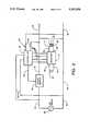
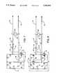
- a common prior art arrangement for a backup power systemis illustrated in the simplified schematic of FIG. 1.
- AC input power from a main sourcesuch as a commercial power system, is received on input lines 10 and 11, and output power is delivered on output lines 12 and 13 to the critical load (not shown).
- a static switch 14is connected in a line 15 between the input line 10 and the output line 12 to isolate the input from the output upon failure of the main AC power system, while a line 16 directly connects the input line 11 and the output line 13.
- a controllerdetects the failure of the AC line power, opens the static switch 14, and turns on an inverter 17 to convert DC voltage, from a storage battery 18, to AC voltage at the inverter output terminals which is provided through a power transformer 19 across the AC output lines 12 and 13.
- a battery charger 21provides DC charging current to the battery 18 by rectifying AC power from a charger transformer 23 which is connected by lines 24 and 25 to the AC power lines.
- the charger transformer 23 and the power transformer 19serve in large part to isolate the typically low voltage DC circuits of the battery charger and inverter from the high voltage AC line circuits.
- a problem commonly associated with a backup power system of the type shown in FIG. 1is that while the AC input voltage is present, the inverter 17 is turned off. It is desirable to have a way of testing the inverter to verify that the inverter is in good operating condition, since the reliability of the inverter is crucial to the backup power system's mission. In the prior art, such inverter testing requires additional circuitry and controls, and thus added expense.
- the battery chargers used in various backup power systemsvary widely in circuit topology, but have common problems.
- the most significant problemarises from the rectifier/capacitor filter combination typically used to convert the AC voltage from the charger transformer to the DC voltage required by the battery, because current is drawn in bursts or pulses at the crest of the input voltage waveform. This causes harmonic distortion of the AC input current.
- Phase-controlled battery chargerscause even worse distortions. While solutions exist to solve this problem, such solutions typically require additional circuitry and thus expense.
- the charger circuitryalso adds expense to such backup power systems, with the cost of the chargers being generally proportional to charging current levels.
- FIG. 3is a circuit schematic of an equivalent circuit for the backup power system of the present invention.
- FIG. 5is a circuit schematic as in FIG. 4 showing the current paths during the energy buildup phase of the positive half cycle.
- FIG. 7is a circuit schematic as in FIG. 4 showing the current paths during the energy buildup state of the negative half cycle.
- FIG. 8is a circuit schematic as in FIG. 4 showing the current paths during the energy release state of the negative half cycle.
- FIG. 9are graphs showing the 60 Hz envelope of inverter current and the inverter current on an expanded time scale during constant frequency inverter charging operation.
- FIG. 11are illustrative graphs showing the timing relationships of various control signals shown in FIG. 10.
- FIG. 12are illustrative graphs of battery charging current and voltage during a recharge of a typical battery.
- FIG. 13is a circuit schematic illustrating the control logic and one shot blocks of FIG. 10 in more detail.
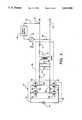
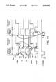
- the inverter 42receives DC voltage from a battery 44 and, under the control of a controller 46, delivers AC output power to the primary 41 of the transformer 39 to provide higher voltage AC power from the secondary 40 to the output terminals 34 and 35.
- the controller 46provides control signals on control lines 47 to the inverter, and may receive lines 51 connected to provide the controller with the output voltage across the output terminals 34 and 35 and lines 54 connected to provide the controller with the voltage across the input lines 31 and 32.
- the controlleralso provides a control signal on a line 52 to the static switch 36 to open and close the switch as appropriate.
- the inverter 42may be of various standard bridge designs, as described further below, and the controller 46 and the static switch 36 may be of standard construction with many types well known in the art of standby and uninterruptible power systems. An example of a back-up uninterruptible power system in which the present invention may be incorporated is shown in U.S.
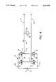
- Each of the switching devices 61-64preferably has an anti-parallel connected diode 85-88, e.g., an intrinsic diode.
- the peak voltage appearing across the nodes A and Bbe less than the voltage V b of the battery 44. This can be insured by proper choice of the nominal battery voltage and the turns ratio of the primary and secondary of the transformer 39, given the expected peak value of the voltage from the AC power system 33.
- Battery charging utilizing the inverter 42 in accordance with the present inventionis carried out in two or three separate states.
- the first statewhich may be called the energy build-up state
- at least the switch 64is turned on and preferably both switches 62 and 64 are turned on. This results in a current path illustrated by the dashed lines labeled 90 in FIG. 5 through the switch (e.g., MOSFET) 64 and through the switch 62 or the anti-parallel diode 85 around the switch 62.
- the switchesare MOSFETs
- currentwill flow in the reverse direction in the channel of the MOSFET 62 until the channel voltage drop exceeds the turn-on threshold of the antiparallel diode, after which current flows in both the MOSFET channel and the intrinsic diode.
- the switches 62 and 64effectively shorts the primary 41 of the transformer, causing the current flowing through the equivalent inductance 80 and an effective equivalent transformer resistor 81 of resistance R to build up rapidly, thus storing energy in the magnetic field of the inductance 80.
- the switches 62 and 64are turned off by the controller, ending the first state.
- the magnitude of the current flowing along the path 90 at turn-offis proportional to the instantaneous line voltage across the lines 34 and 35, which changes over time.
- the voltage across the lines 34 and 35 provided by the effective voltage source 83is substantially constant.
- the peak current flowing along the path 90will also be low.
- the current magnitudewill reach its highest value.
- the graph 95is the envelope of the inverter current waveform with the inverter switching at a higher frequency, e.g., 19,200 Hertz, and for clarity of illustration the individual inverter switching cycles are not shown.
- the envelope of the currenttraces out the 60 Hertz waveform 95.
- the peak of the inverter currentis proportional to the line voltage, which in this case is a 60 Hertz sine wave.
- the inverter-chargerdraws a non-distorted current proportional to and in phase with the input voltage waveform.
- the power transformer and inverteracting as a charger for the battery, appears as a purely resistive load to the input power lines 31 and 32. Therefore, power factor correction is achieved without requiring additional control circuitry.
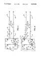
- the signal /TRIGis shown by the graph 135, the switching control signal 1B to the switching device 62 by the graph 136, the switching control signal 2B to the switching device 64 by the graph 137, the signal BSON on the line 112 by the graph 138, an output signal CLRST on a line 130 from the control logic by the graph 139, and a signal /CYCEND on a line 131 by the graph 140.
- the signal /TRIGgoes low at point A, both bottom switches 62 and 64 of the H-bridge inverter are turned on as the control signals 1B and 2B go high.
- the signals /TRIG going lowalso triggers the one shot 110 to put out the fixed output timing pulse BSON on the line 112.
- this pulsedetermines the magnitude of the battery charge current, with longer pulses yielding higher current.
- the signal BSONwill go low at point B, causing the bottom inverter switches 62 and 64 to turn off. This marks the beginning of the discharge state where the energy that was stored in the leakage inductances of the transformer will cause a current to flow into one of the two body diodes of the upper inverter switches. Which diode the current flows in depends on the instantaneous polarity of the AC line voltage.
- a conduction limit circuitmonitors the voltage drop across the diodes 86 and 88 on lines 116 and 117 passed through diodes 120 and 119, respectively, to a line 121 which is connected to ground through a resistor 122.
- the line 121is connected to the base of a transistor 123, the emitter of which is connected through a resistor 124 to the DC voltage on the line 65, and the collector of which is connected to ground through a resistor 125.
- FIG. 12Typical battery voltage and current (RMS) during a charge of the battery using the inverter in accordance with the present invention is illustrated in FIG. 12.
- the inverter chargeris operating in its normal constant current mode, illustrating recharge current by the line 150 and battery voltage by the line 151.
- the period of time marked “B”is a current taper mode where the on time of the one shot (the energy build up state time) is shortened. The on time is shortened so that the charge current is reduced as the battery voltage increases.
- batterieswill show a faster rate of increase of the battery voltage near full charge than when charge is low. By tapering the current, it is possible to decrease the rate of rise of battery voltage, allowing easier monitoring of the charger turnoff voltage.
- control logicrepresented by programmable logic device (PEEL) 191
- PELprogrammable logic device
Landscapes
- Engineering & Computer Science (AREA)
- Power Engineering (AREA)
- Business, Economics & Management (AREA)
- Emergency Management (AREA)
- Charge And Discharge Circuits For Batteries Or The Like (AREA)
Abstract
Description
Claims (22)
Priority Applications (2)
| Application Number | Priority Date | Filing Date | Title |
|---|---|---|---|
| US07/805,496US5302858A (en) | 1991-12-11 | 1991-12-11 | Method and apparatus for providing battery charging in a backup power system |
| PCT/US1992/010899WO1993012570A1 (en) | 1991-12-11 | 1992-12-03 | Method and apparatus for providing battery charging in a backup power system |
Applications Claiming Priority (1)
| Application Number | Priority Date | Filing Date | Title |
|---|---|---|---|
| US07/805,496US5302858A (en) | 1991-12-11 | 1991-12-11 | Method and apparatus for providing battery charging in a backup power system |
Publications (1)
| Publication Number | Publication Date |
|---|---|
| US5302858Atrue US5302858A (en) | 1994-04-12 |
Family
ID=25191715
Family Applications (1)
| Application Number | Title | Priority Date | Filing Date |
|---|---|---|---|
| US07/805,496Expired - LifetimeUS5302858A (en) | 1991-12-11 | 1991-12-11 | Method and apparatus for providing battery charging in a backup power system |
Country Status (2)
| Country | Link |
|---|---|
| US (1) | US5302858A (en) |
| WO (1) | WO1993012570A1 (en) |
Cited By (66)
| Publication number | Priority date | Publication date | Assignee | Title |
|---|---|---|---|---|
| US5532525A (en)* | 1994-06-02 | 1996-07-02 | Albar, Inc. | Congeneration power system |
| GB2298326A (en)* | 1995-02-22 | 1996-08-28 | Alpha Tech Inc | Uninterruptible power supply with switch mode converter |
| US5596512A (en)* | 1994-08-15 | 1997-01-21 | Thermo King Corporation | Method of determining the condition of a back-up battery for a real time clock |
| US5633577A (en)* | 1994-06-06 | 1997-05-27 | Nippondenso Co., Ltd. | Battery charging system for electric vehicles |
| US5638244A (en)* | 1993-10-29 | 1997-06-10 | Alpha Technologies, Inc. | Apparatus and methods for generating uninterruptible AC power signals |
| US5646502A (en)* | 1995-08-28 | 1997-07-08 | Nsi Enterprises, Inc. | Emergency lighting circuit for shunt-regulated battery charging and lamp operation |
| US5648716A (en)* | 1994-03-14 | 1997-07-15 | Devilbiss; Roger S. | Power control circuit for a battery charger |
| US5689957A (en)* | 1996-07-12 | 1997-11-25 | Thermotek, Inc. | Temperature controller for low voltage thermoelectric cooling or warming boxes and method therefor |
| US5739595A (en)* | 1992-10-28 | 1998-04-14 | Alpha Technologies, Inc. | Apparatus and methods for generating an AC power signal for cable tv distribution systems |
| WO1998033268A1 (en)* | 1997-01-24 | 1998-07-30 | Baker Hughes Incorporated | Boost mode power conversion |
| US5834858A (en)* | 1995-04-05 | 1998-11-10 | Electronic Design & Manufacturing Inc. | Emergency power supply |
| EP0825699A3 (en)* | 1996-08-01 | 1999-04-14 | Benchmarq Microelectronics, Inc. | Phase controlled switching regulator power switch |
| WO1999027630A1 (en)* | 1997-11-25 | 1999-06-03 | Powerware Corporation | Charge circuits for ups |
| US5929538A (en)* | 1997-06-27 | 1999-07-27 | Abacus Controls Inc. | Multimode power processor |
| US6104172A (en)* | 1997-07-01 | 2000-08-15 | Power-One | Power factor corrector |
| US6108217A (en)* | 1999-10-19 | 2000-08-22 | Ivi Checkmate Ltd. | Backup power circuit |
| US20020153778A1 (en)* | 2001-04-24 | 2002-10-24 | Oughton George W. | Ferroelectric transformer-free uninterruptible power supply (UPS) systems and methods for communications signal distribution systems |
| US6741896B1 (en)* | 1998-04-02 | 2004-05-25 | Honeywell International Inc. | Power backup application to maintain normal flight recorder operation for a specified period of time in case of aircraft power failure or interruption |
| US20040136208A1 (en)* | 2002-10-21 | 2004-07-15 | Advanced Power Technology, Inc., A Delaware Corporation | Power converter method and apparatus having high input power factor and low harmonic distortion |
| US20040201278A1 (en)* | 2003-04-11 | 2004-10-14 | Delta Electronics, Inc. | Charging circuit in uninterruptible power supply system |
| US20050024905A1 (en)* | 2003-07-29 | 2005-02-03 | Sanyo Electric Co., Ltd. | Uninterruptible power supply device |
| US20050162129A1 (en)* | 2004-01-23 | 2005-07-28 | Srdan Mutabdzija | Method and apparatus for monitoring energy storage devices |
| US20050162836A1 (en)* | 2004-01-23 | 2005-07-28 | James Briggs | Modular UPS |
| US20060043797A1 (en)* | 2004-08-31 | 2006-03-02 | American Power Conversion Corporation | Method and apparatus for providing uninterruptible power |
| US20060043793A1 (en)* | 2004-08-31 | 2006-03-02 | American Power Conversion Corporation | Method and apparatus for providing uninterruptible power |
| US20060044846A1 (en)* | 2004-08-31 | 2006-03-02 | American Power Conversion Corporation | Method and apparatus for providing uninterruptible power |
| CN1319244C (en)* | 2003-05-07 | 2007-05-30 | 台达电子工业股份有限公司 | Charging circuit of online interactive uninterruptible power supply |
| US20070223256A1 (en)* | 2004-04-21 | 2007-09-27 | Mitsubishi Electric Corp. | Power Device |
| US20080157601A1 (en)* | 2004-01-23 | 2008-07-03 | American Power Conversion Corporation | Methods and apparatus for providing uninterruptible power |
| US7456518B2 (en) | 2004-08-31 | 2008-11-25 | American Power Conversion Corporation | Method and apparatus for providing uninterruptible power |
| US20090033283A1 (en)* | 2007-08-03 | 2009-02-05 | Mirza Akmal Beg | Adjustable battery charger for ups |
| US20090146611A1 (en)* | 2007-12-05 | 2009-06-11 | Rui Hong Weng | Automatic discharging apparatus |
| US20090201703A1 (en)* | 2008-02-07 | 2009-08-13 | Damir Klikic | Systems and Methods for Uninterruptible Power Supply Control |
| US20090219001A1 (en)* | 2008-03-03 | 2009-09-03 | Denso Corporation | Drive controller for power conversion circuit |
| US20090244944A1 (en)* | 2008-03-25 | 2009-10-01 | Delta Electronics, Inc. | Power converter system that operates efficiently over a range of load conditions |
| US20090251106A1 (en)* | 2008-04-02 | 2009-10-08 | American Power Conversion Corporation | Non-isolated charger with bi-polar inputs |
| USD605589S1 (en)* | 2006-10-06 | 2009-12-08 | Hdm Systems Corporation | Inverter charger system |
| US20100007211A1 (en)* | 2007-01-12 | 2010-01-14 | Meidensha Corporation | Control device and control method for power conversion system having instantaneous voltage drop - service interruption counter-measure functions |
| US20110006737A1 (en)* | 2009-07-10 | 2011-01-13 | Narayana Prakash Saligram | Battery charging method and apparatus |
| EP2278686A1 (en) | 2004-08-31 | 2011-01-26 | American Power Conversion Corporation | Method and apparatus for providing uninterruptible power |
| US20110078468A1 (en)* | 2009-09-28 | 2011-03-31 | Kabushiki Kaisha Toshiba | Power controller, electronic apparatus and power control method |
| US20110241620A1 (en)* | 2010-03-31 | 2011-10-06 | Winmate Communication Inc. | Charging apparatus for laptop computer with multi-batteries and method for the same |
| EP2290785A3 (en)* | 2009-08-28 | 2013-03-06 | Cyber Power Systems Inc. | Power-saving line interactive uninterruptible power system |
| US20130147269A1 (en)* | 2010-04-09 | 2013-06-13 | Michael Zimmermann | Modular LED Lighting System Having Emergency Light Function |
| TWI407661B (en)* | 2010-02-26 | 2013-09-01 | Winmate Comm Inc | Apparatus and method for charging multi-battery in notebook |
| US20130257062A1 (en)* | 2012-03-30 | 2013-10-03 | Kabushiki Kaisha Toyota Jidoshokki | Power circuit |
| US8575779B2 (en) | 2010-02-18 | 2013-11-05 | Alpha Technologies Inc. | Ferroresonant transformer for use in uninterruptible power supplies |
| US20140184140A1 (en)* | 2012-12-28 | 2014-07-03 | Hyundai Motor Company | Charger and driving method thereof |
| US8803361B2 (en) | 2011-01-19 | 2014-08-12 | Schneider Electric It Corporation | Apparatus and method for providing uninterruptible power |
| US8853887B2 (en) | 2010-11-12 | 2014-10-07 | Schneider Electric It Corporation | Static bypass switch with built in transfer switch capabilities |
| US20140336840A1 (en)* | 2011-12-09 | 2014-11-13 | The Aes Corporation | Method and system for performance management of an energy storage device |
| US9030045B2 (en) | 2011-01-23 | 2015-05-12 | Alpha Technologies Inc. | Switching systems and methods for use in uninterruptible power supplies |
| US9037443B1 (en) | 2011-10-16 | 2015-05-19 | Alpha Technologies Inc. | Systems and methods for solar power equipment |
| US9234916B2 (en) | 2012-05-11 | 2016-01-12 | Alpha Technologies Inc. | Status monitoring cables for generators |
| US9312726B2 (en) | 2011-01-23 | 2016-04-12 | Alpha Technologies Inc. | Uninterruptible power supplies for use in a distributed network |
| JP2016073068A (en)* | 2014-09-29 | 2016-05-09 | 矢崎総業株式会社 | Power supply box device for vehicles |
| US9397509B2 (en) | 2011-01-22 | 2016-07-19 | Alpha Technologies Inc. | Charge equalization systems and methods for battery systems and uninterruptible power supplies |
| USRE46156E1 (en) | 2009-04-01 | 2016-09-20 | Eaglepicher Technologies Llc | Hybrid energy storage system, renewable energy system including the storage system, and method of using same |
| CN106486975A (en)* | 2016-10-31 | 2017-03-08 | 广西电网有限责任公司电力科学研究院 | A kind of online by-pass method of electric power electric transformer H bridge cascade rectifier bridge |
| US9952103B2 (en) | 2011-12-22 | 2018-04-24 | Schneider Electric It Corporation | Analysis of effect of transient events on temperature in a data center |
| US10074981B2 (en) | 2015-09-13 | 2018-09-11 | Alpha Technologies Inc. | Power control systems and methods |
| US10381867B1 (en) | 2015-10-16 | 2019-08-13 | Alpha Technologeis Services, Inc. | Ferroresonant transformer systems and methods with selectable input and output voltages for use in uninterruptible power supplies |
| US10635122B2 (en) | 2017-07-14 | 2020-04-28 | Alpha Technologies Services, Inc. | Voltage regulated AC power supply systems and methods |
| US10965152B2 (en) | 2010-10-18 | 2021-03-30 | Alpha Technologies Services, Inc. | Uninterruptible power supply systems and methods for communication systems |
| US11076507B2 (en) | 2007-05-15 | 2021-07-27 | Schneider Electric It Corporation | Methods and systems for managing facility power and cooling |
| EP2896109B1 (en)* | 2012-09-14 | 2024-01-03 | Vertiv S.R.L. | Uninterruptible power supply system with fast transfer for undervoltage source line failures |
Families Citing this family (1)
| Publication number | Priority date | Publication date | Assignee | Title |
|---|---|---|---|---|
| FR2767612B1 (en)* | 1997-08-21 | 2002-06-14 | Gec Alsthom Transport Sa | DIRECT CURRENT ENERGY CONVERSION DEVICE |
Citations (14)
| Publication number | Priority date | Publication date | Assignee | Title |
|---|---|---|---|---|
| DE2602789A1 (en)* | 1976-01-26 | 1977-07-28 | Elektr Strassenverkehr Ges | Battery charger for electric cars - has bridge circuit with non-controlled rectifiers connected to AC voltage source |
| US4277692A (en)* | 1979-06-04 | 1981-07-07 | Tab Products Company | Continuous power source with bi-directional converter |
| US4366389A (en)* | 1981-07-13 | 1982-12-28 | Reliance Electric Company | Continuously operating standby A-C power system |
| US4400624A (en)* | 1982-04-29 | 1983-08-23 | Bell Telephone Laboratories, Incorporated | Uninterruptible power supplies |
| US4400625A (en)* | 1981-11-30 | 1983-08-23 | Reliance Electric Company | Standby A-C power system with transfer compensation circuitry |
| US4475047A (en)* | 1982-04-29 | 1984-10-02 | At&T Bell Laboratories | Uninterruptible power supplies |
| US4604530A (en)* | 1983-08-16 | 1986-08-05 | Kabushiki Kaisha Meidensha | Power supply equipment backup system for interruption of service |
| US4616305A (en)* | 1985-02-11 | 1986-10-07 | Eaton Corporation | AC/DC power MOSFET reversing H-drive system |
| US4673825A (en)* | 1985-02-15 | 1987-06-16 | Exide Electronics Corporation | Uninterruptible power supply with isolated bypass winding |
| US4740739A (en)* | 1987-02-10 | 1988-04-26 | Premier Engineered Products Corporation | Battery charging apparatus and method |
| US4829225A (en)* | 1985-10-23 | 1989-05-09 | Electronic Power Devices, Corp. | Rapid battery charger, discharger and conditioner |
| US4882717A (en)* | 1987-09-21 | 1989-11-21 | Seiko Epson Corporation | Charging circuit for an analog electronic timepiece |
| US4920475A (en)* | 1988-03-07 | 1990-04-24 | California Institute Of Technology | Integrated traction inverter and battery charger apparatus |
| US5221862A (en)* | 1990-10-08 | 1993-06-22 | Merlin Gerin | A.c. electrical power supply system including a backup power supply equipped with an inverter operating in reversible mode |
- 1991
- 1991-12-11USUS07/805,496patent/US5302858A/ennot_activeExpired - Lifetime
- 1992
- 1992-12-03WOPCT/US1992/010899patent/WO1993012570A1/enactiveApplication Filing
Patent Citations (14)
| Publication number | Priority date | Publication date | Assignee | Title |
|---|---|---|---|---|
| DE2602789A1 (en)* | 1976-01-26 | 1977-07-28 | Elektr Strassenverkehr Ges | Battery charger for electric cars - has bridge circuit with non-controlled rectifiers connected to AC voltage source |
| US4277692A (en)* | 1979-06-04 | 1981-07-07 | Tab Products Company | Continuous power source with bi-directional converter |
| US4366389A (en)* | 1981-07-13 | 1982-12-28 | Reliance Electric Company | Continuously operating standby A-C power system |
| US4400625A (en)* | 1981-11-30 | 1983-08-23 | Reliance Electric Company | Standby A-C power system with transfer compensation circuitry |
| US4400624A (en)* | 1982-04-29 | 1983-08-23 | Bell Telephone Laboratories, Incorporated | Uninterruptible power supplies |
| US4475047A (en)* | 1982-04-29 | 1984-10-02 | At&T Bell Laboratories | Uninterruptible power supplies |
| US4604530A (en)* | 1983-08-16 | 1986-08-05 | Kabushiki Kaisha Meidensha | Power supply equipment backup system for interruption of service |
| US4616305A (en)* | 1985-02-11 | 1986-10-07 | Eaton Corporation | AC/DC power MOSFET reversing H-drive system |
| US4673825A (en)* | 1985-02-15 | 1987-06-16 | Exide Electronics Corporation | Uninterruptible power supply with isolated bypass winding |
| US4829225A (en)* | 1985-10-23 | 1989-05-09 | Electronic Power Devices, Corp. | Rapid battery charger, discharger and conditioner |
| US4740739A (en)* | 1987-02-10 | 1988-04-26 | Premier Engineered Products Corporation | Battery charging apparatus and method |
| US4882717A (en)* | 1987-09-21 | 1989-11-21 | Seiko Epson Corporation | Charging circuit for an analog electronic timepiece |
| US4920475A (en)* | 1988-03-07 | 1990-04-24 | California Institute Of Technology | Integrated traction inverter and battery charger apparatus |
| US5221862A (en)* | 1990-10-08 | 1993-06-22 | Merlin Gerin | A.c. electrical power supply system including a backup power supply equipped with an inverter operating in reversible mode |
Cited By (127)
| Publication number | Priority date | Publication date | Assignee | Title |
|---|---|---|---|---|
| US5739595A (en)* | 1992-10-28 | 1998-04-14 | Alpha Technologies, Inc. | Apparatus and methods for generating an AC power signal for cable tv distribution systems |
| US5642002A (en)* | 1993-10-29 | 1997-06-24 | Alpha Technologies | Apparatus and methods for generating uninterruptible AC power signals |
| US5638244A (en)* | 1993-10-29 | 1997-06-10 | Alpha Technologies, Inc. | Apparatus and methods for generating uninterruptible AC power signals |
| US5648716A (en)* | 1994-03-14 | 1997-07-15 | Devilbiss; Roger S. | Power control circuit for a battery charger |
| US5532525A (en)* | 1994-06-02 | 1996-07-02 | Albar, Inc. | Congeneration power system |
| US5633577A (en)* | 1994-06-06 | 1997-05-27 | Nippondenso Co., Ltd. | Battery charging system for electric vehicles |
| US5596512A (en)* | 1994-08-15 | 1997-01-21 | Thermo King Corporation | Method of determining the condition of a back-up battery for a real time clock |
| US5760495A (en)* | 1995-02-22 | 1998-06-02 | Alpha Technologies, Inc. | Inverter/charger circuit for uninterruptible power supplies |
| GB2298326A (en)* | 1995-02-22 | 1996-08-28 | Alpha Tech Inc | Uninterruptible power supply with switch mode converter |
| US5834858A (en)* | 1995-04-05 | 1998-11-10 | Electronic Design & Manufacturing Inc. | Emergency power supply |
| US5646502A (en)* | 1995-08-28 | 1997-07-08 | Nsi Enterprises, Inc. | Emergency lighting circuit for shunt-regulated battery charging and lamp operation |
| US5689957A (en)* | 1996-07-12 | 1997-11-25 | Thermotek, Inc. | Temperature controller for low voltage thermoelectric cooling or warming boxes and method therefor |
| US6072708A (en)* | 1996-08-01 | 2000-06-06 | Benchmarq Microelectronics, Inc. | Phase controlled switching regulator power supply |
| EP0825699A3 (en)* | 1996-08-01 | 1999-04-14 | Benchmarq Microelectronics, Inc. | Phase controlled switching regulator power switch |
| US5946202A (en)* | 1997-01-24 | 1999-08-31 | Baker Hughes Incorporated | Boost mode power conversion |
| WO1998033268A1 (en)* | 1997-01-24 | 1998-07-30 | Baker Hughes Incorporated | Boost mode power conversion |
| US5929538A (en)* | 1997-06-27 | 1999-07-27 | Abacus Controls Inc. | Multimode power processor |
| US6104172A (en)* | 1997-07-01 | 2000-08-15 | Power-One | Power factor corrector |
| AU761505B2 (en)* | 1997-11-25 | 2003-06-05 | Powerware Corporation | Charge circuits for UPS |
| WO1999027630A1 (en)* | 1997-11-25 | 1999-06-03 | Powerware Corporation | Charge circuits for ups |
| US6121756A (en)* | 1997-11-25 | 2000-09-19 | Powerware Corporation | Charger |
| US6741896B1 (en)* | 1998-04-02 | 2004-05-25 | Honeywell International Inc. | Power backup application to maintain normal flight recorder operation for a specified period of time in case of aircraft power failure or interruption |
| US6108217A (en)* | 1999-10-19 | 2000-08-22 | Ivi Checkmate Ltd. | Backup power circuit |
| US20020153778A1 (en)* | 2001-04-24 | 2002-10-24 | Oughton George W. | Ferroelectric transformer-free uninterruptible power supply (UPS) systems and methods for communications signal distribution systems |
| US6933626B2 (en) | 2001-04-24 | 2005-08-23 | Alphatec Ltd. | Ferroelectric transformer-free uninterruptible power supply (UPS) systems and methods for communications signal distribution systems |
| US20040136208A1 (en)* | 2002-10-21 | 2004-07-15 | Advanced Power Technology, Inc., A Delaware Corporation | Power converter method and apparatus having high input power factor and low harmonic distortion |
| US7157886B2 (en) | 2002-10-21 | 2007-01-02 | Microsemi Corp. —Power Products Group | Power converter method and apparatus having high input power factor and low harmonic distortion |
| US20040201278A1 (en)* | 2003-04-11 | 2004-10-14 | Delta Electronics, Inc. | Charging circuit in uninterruptible power supply system |
| US7230353B2 (en) | 2003-04-11 | 2007-06-12 | Delta Electronics, Inc. | Charging circuit in uninterruptible power supply system |
| CN1319244C (en)* | 2003-05-07 | 2007-05-30 | 台达电子工业股份有限公司 | Charging circuit of online interactive uninterruptible power supply |
| US20050024905A1 (en)* | 2003-07-29 | 2005-02-03 | Sanyo Electric Co., Ltd. | Uninterruptible power supply device |
| US7026726B2 (en)* | 2003-07-29 | 2006-04-11 | Sanyo Electric Co., Ltd. | Uninterruptible power supply device |
| CN100358216C (en)* | 2003-07-29 | 2007-12-26 | 三洋电机株式会社 | Uninterruptible power supply device |
| US7379305B2 (en) | 2004-01-23 | 2008-05-27 | American Power Conversion Corporation | Modular UPS |
| US8854824B2 (en) | 2004-01-23 | 2014-10-07 | Schneider Electric It Corporation | Modular UPS |
| US8162417B2 (en) | 2004-01-23 | 2012-04-24 | American Power Conversion Corporation | Modular UPS |
| US7615890B2 (en) | 2004-01-23 | 2009-11-10 | American Power Conversion Corporation | Methods and apparatus for providing uninterruptible power |
| US8604640B2 (en) | 2004-01-23 | 2013-12-10 | Schneider Electric It Corporation | Methods and apparatus for providing uninterruptible power |
| US20100049457A1 (en)* | 2004-01-23 | 2010-02-25 | American Power Conversion Corporation | Method and apparatus for monitoring energy storage devices |
| US20050162836A1 (en)* | 2004-01-23 | 2005-07-28 | James Briggs | Modular UPS |
| US8148846B2 (en) | 2004-01-23 | 2012-04-03 | American Power Conversion Corporation | Methods and apparatus for providing uninterruptible power |
| US20080157601A1 (en)* | 2004-01-23 | 2008-07-03 | American Power Conversion Corporation | Methods and apparatus for providing uninterruptible power |
| US7446433B2 (en) | 2004-01-23 | 2008-11-04 | American Power Conversion Corporation | Methods and apparatus for providing uninterruptible power |
| US20080278889A1 (en)* | 2004-01-23 | 2008-11-13 | American Power Conversion Corporation | Modular ups |
| US7911088B2 (en) | 2004-01-23 | 2011-03-22 | American Power Conversion Corporation | Method and apparatus for monitoring energy storage devices |
| US20050162129A1 (en)* | 2004-01-23 | 2005-07-28 | Srdan Mutabdzija | Method and apparatus for monitoring energy storage devices |
| US7612472B2 (en) | 2004-01-23 | 2009-11-03 | American Power Conversion Corporation | Method and apparatus for monitoring energy storage devices |
| US20100201194A1 (en)* | 2004-01-23 | 2010-08-12 | American Power Conversion Corporation | Methods and apparatus for providing uninterruptible power |
| US20070223256A1 (en)* | 2004-04-21 | 2007-09-27 | Mitsubishi Electric Corp. | Power Device |
| US7957164B2 (en)* | 2004-04-21 | 2011-06-07 | Mitsubishi Electric Corporation | Power device for supplying AC voltage to a load having a discharge part |
| US7737580B2 (en) | 2004-08-31 | 2010-06-15 | American Power Conversion Corporation | Method and apparatus for providing uninterruptible power |
| US20060043797A1 (en)* | 2004-08-31 | 2006-03-02 | American Power Conversion Corporation | Method and apparatus for providing uninterruptible power |
| US8053927B2 (en) | 2004-08-31 | 2011-11-08 | American Power Conversion Corporation | Method and apparatus for providing uninterruptible power |
| US20060043793A1 (en)* | 2004-08-31 | 2006-03-02 | American Power Conversion Corporation | Method and apparatus for providing uninterruptible power |
| US20110227415A1 (en)* | 2004-08-31 | 2011-09-22 | American Power Conversion Corporation | Method and apparatus for providing uninterruptible power |
| US7939968B2 (en) | 2004-08-31 | 2011-05-10 | American Power Conversion Corporation | Method and apparatus for providing uninterruptible power |
| US20060044846A1 (en)* | 2004-08-31 | 2006-03-02 | American Power Conversion Corporation | Method and apparatus for providing uninterruptible power |
| US7274112B2 (en) | 2004-08-31 | 2007-09-25 | American Power Conversion Corporation | Method and apparatus for providing uninterruptible power |
| US7456518B2 (en) | 2004-08-31 | 2008-11-25 | American Power Conversion Corporation | Method and apparatus for providing uninterruptible power |
| US20100225170A1 (en)* | 2004-08-31 | 2010-09-09 | American Power Conversion Corporation | Method and apparatus for providing uninterruptible power |
| EP2287995A1 (en) | 2004-08-31 | 2011-02-23 | American Power Conversion Corporation | Method and apparatus for providing uninterruptible power |
| EP2282393A1 (en) | 2004-08-31 | 2011-02-09 | American Power Conversion Corporation | Method and apparatus for providing uninterruptible power |
| US7855472B2 (en) | 2004-08-31 | 2010-12-21 | American Power Conversion Corporation | Method and apparatus for providing uninterruptible power |
| EP2278686A1 (en) | 2004-08-31 | 2011-01-26 | American Power Conversion Corporation | Method and apparatus for providing uninterruptible power |
| USD605589S1 (en)* | 2006-10-06 | 2009-12-08 | Hdm Systems Corporation | Inverter charger system |
| US8207632B2 (en)* | 2007-01-12 | 2012-06-26 | Meidensha Corporation | Control device for uninterruptible power supply |
| JP4859932B2 (en)* | 2007-01-12 | 2012-01-25 | 株式会社明電舎 | Control device and control method for power conversion system having instantaneous voltage drop / power failure countermeasure function |
| US20100007211A1 (en)* | 2007-01-12 | 2010-01-14 | Meidensha Corporation | Control device and control method for power conversion system having instantaneous voltage drop - service interruption counter-measure functions |
| US11503744B2 (en) | 2007-05-15 | 2022-11-15 | Schneider Electric It Corporation | Methods and systems for managing facility power and cooling |
| US11076507B2 (en) | 2007-05-15 | 2021-07-27 | Schneider Electric It Corporation | Methods and systems for managing facility power and cooling |
| US7944182B2 (en) | 2007-08-03 | 2011-05-17 | American Power Conversion Corporation | Adjustable battery charger for UPS |
| US20090033283A1 (en)* | 2007-08-03 | 2009-02-05 | Mirza Akmal Beg | Adjustable battery charger for ups |
| US20090146611A1 (en)* | 2007-12-05 | 2009-06-11 | Rui Hong Weng | Automatic discharging apparatus |
| US20090201703A1 (en)* | 2008-02-07 | 2009-08-13 | Damir Klikic | Systems and Methods for Uninterruptible Power Supply Control |
| US8116105B2 (en) | 2008-02-07 | 2012-02-14 | American Power Conversion Corporation | Systems and methods for uninterruptible power supply control |
| US20090219001A1 (en)* | 2008-03-03 | 2009-09-03 | Denso Corporation | Drive controller for power conversion circuit |
| US8094474B2 (en)* | 2008-03-03 | 2012-01-10 | Denso Corporation | Drive controller for power conversion circuit |
| TWI450482B (en)* | 2008-03-25 | 2014-08-21 | Delta Electronics Inc | A power converter system that operates efficiently over a range of load conditions |
| US8179698B2 (en)* | 2008-03-25 | 2012-05-15 | Delta Electronics, Inc. | Power converter system that operates efficiently over a range of load conditions |
| US20090244944A1 (en)* | 2008-03-25 | 2009-10-01 | Delta Electronics, Inc. | Power converter system that operates efficiently over a range of load conditions |
| US7834587B1 (en) | 2008-04-02 | 2010-11-16 | American Power Conversion Corporation | Non-isolated charger with bi-polar inputs |
| US8004240B2 (en) | 2008-04-02 | 2011-08-23 | American Power Conversion Corporation | Non-isolated charger with bi-polar inputs |
| US20110109271A1 (en)* | 2008-04-02 | 2011-05-12 | American Power Conversion Corporation | Non-isolated charger with bi-polar inputs |
| US7759900B2 (en) | 2008-04-02 | 2010-07-20 | American Power Conversion Corporation | Non-isolated charger with bi-polar inputs |
| US20090251106A1 (en)* | 2008-04-02 | 2009-10-08 | American Power Conversion Corporation | Non-isolated charger with bi-polar inputs |
| US20100270977A1 (en)* | 2008-04-02 | 2010-10-28 | American Power Conversion Corporation | Non-isolated charger with bi-polar inputs |
| USRE46156E1 (en) | 2009-04-01 | 2016-09-20 | Eaglepicher Technologies Llc | Hybrid energy storage system, renewable energy system including the storage system, and method of using same |
| US20110006737A1 (en)* | 2009-07-10 | 2011-01-13 | Narayana Prakash Saligram | Battery charging method and apparatus |
| US8581554B2 (en) | 2009-07-10 | 2013-11-12 | Schneider Electric It Corporation | Battery charging method and apparatus |
| EP2290785A3 (en)* | 2009-08-28 | 2013-03-06 | Cyber Power Systems Inc. | Power-saving line interactive uninterruptible power system |
| US20110078468A1 (en)* | 2009-09-28 | 2011-03-31 | Kabushiki Kaisha Toshiba | Power controller, electronic apparatus and power control method |
| US9633781B2 (en) | 2010-02-18 | 2017-04-25 | Alpha Technologies Inc. | Ferroresonant transformer for use in uninterruptible power supplies |
| US8575779B2 (en) | 2010-02-18 | 2013-11-05 | Alpha Technologies Inc. | Ferroresonant transformer for use in uninterruptible power supplies |
| US10819144B2 (en) | 2010-02-18 | 2020-10-27 | Alpha Technologies Services, Inc. | Ferroresonant transformer for use in uninterruptible power supplies |
| TWI407661B (en)* | 2010-02-26 | 2013-09-01 | Winmate Comm Inc | Apparatus and method for charging multi-battery in notebook |
| US20110241620A1 (en)* | 2010-03-31 | 2011-10-06 | Winmate Communication Inc. | Charging apparatus for laptop computer with multi-batteries and method for the same |
| US8390254B2 (en)* | 2010-03-31 | 2013-03-05 | Winmate Communication Inc. | Charging apparatus for laptop computer with multi-batteries and method for the same |
| US10143064B2 (en)* | 2010-04-09 | 2018-11-27 | Tridonic Ag | Modular LED lighting system having emergency light function |
| US20130147269A1 (en)* | 2010-04-09 | 2013-06-13 | Michael Zimmermann | Modular LED Lighting System Having Emergency Light Function |
| US10965152B2 (en) | 2010-10-18 | 2021-03-30 | Alpha Technologies Services, Inc. | Uninterruptible power supply systems and methods for communication systems |
| US8853887B2 (en) | 2010-11-12 | 2014-10-07 | Schneider Electric It Corporation | Static bypass switch with built in transfer switch capabilities |
| US8803361B2 (en) | 2011-01-19 | 2014-08-12 | Schneider Electric It Corporation | Apparatus and method for providing uninterruptible power |
| US9853497B2 (en) | 2011-01-22 | 2017-12-26 | Alpha Technologies Inc. | Charge equalization systems and methods for battery systems and uninterruptible power supplies |
| US10312728B2 (en) | 2011-01-22 | 2019-06-04 | Alpha Technologies Services, Inc. | Charge equalization systems and methods for battery systems and uninterruptible power supplies |
| US9397509B2 (en) | 2011-01-22 | 2016-07-19 | Alpha Technologies Inc. | Charge equalization systems and methods for battery systems and uninterruptible power supplies |
| US9312726B2 (en) | 2011-01-23 | 2016-04-12 | Alpha Technologies Inc. | Uninterruptible power supplies for use in a distributed network |
| US10355521B2 (en) | 2011-01-23 | 2019-07-16 | Alpha Technologies Services, Inc. | Switching systems and methods for use in uninterruptible power supplies |
| US9812900B2 (en) | 2011-01-23 | 2017-11-07 | Alpha Technologies Inc. | Switching systems and methods for use in uninterruptible power supplies |
| US9030045B2 (en) | 2011-01-23 | 2015-05-12 | Alpha Technologies Inc. | Switching systems and methods for use in uninterruptible power supplies |
| US10103571B2 (en) | 2011-01-23 | 2018-10-16 | Alpha Technologies Inc. | Uninterruptible power supplies for use in a distributed network |
| US9037443B1 (en) | 2011-10-16 | 2015-05-19 | Alpha Technologies Inc. | Systems and methods for solar power equipment |
| US10042963B2 (en) | 2011-10-16 | 2018-08-07 | Alpha Technologies Inc. | Systems and methods for solar power equipment |
| US10886742B2 (en)* | 2011-12-09 | 2021-01-05 | The Aes Corporation | Method and system for performance management of an energy storage device |
| US20140336840A1 (en)* | 2011-12-09 | 2014-11-13 | The Aes Corporation | Method and system for performance management of an energy storage device |
| US9952103B2 (en) | 2011-12-22 | 2018-04-24 | Schneider Electric It Corporation | Analysis of effect of transient events on temperature in a data center |
| US9188101B2 (en)* | 2012-03-30 | 2015-11-17 | Kabushiki Kaisha Toyota Jidoshokki | Power circuit |
| US20130257062A1 (en)* | 2012-03-30 | 2013-10-03 | Kabushiki Kaisha Toyota Jidoshokki | Power circuit |
| US9234916B2 (en) | 2012-05-11 | 2016-01-12 | Alpha Technologies Inc. | Status monitoring cables for generators |
| EP2896109B1 (en)* | 2012-09-14 | 2024-01-03 | Vertiv S.R.L. | Uninterruptible power supply system with fast transfer for undervoltage source line failures |
| US20140184140A1 (en)* | 2012-12-28 | 2014-07-03 | Hyundai Motor Company | Charger and driving method thereof |
| US9431840B2 (en)* | 2012-12-28 | 2016-08-30 | Hyundai Motor Company | Charger and driving method thereof |
| JP2016073068A (en)* | 2014-09-29 | 2016-05-09 | 矢崎総業株式会社 | Power supply box device for vehicles |
| US10790665B2 (en) | 2015-09-13 | 2020-09-29 | Alpha Technologies Services, Inc. | Power control systems and methods |
| US10074981B2 (en) | 2015-09-13 | 2018-09-11 | Alpha Technologies Inc. | Power control systems and methods |
| US10381867B1 (en) | 2015-10-16 | 2019-08-13 | Alpha Technologeis Services, Inc. | Ferroresonant transformer systems and methods with selectable input and output voltages for use in uninterruptible power supplies |
| CN106486975A (en)* | 2016-10-31 | 2017-03-08 | 广西电网有限责任公司电力科学研究院 | A kind of online by-pass method of electric power electric transformer H bridge cascade rectifier bridge |
| US10635122B2 (en) | 2017-07-14 | 2020-04-28 | Alpha Technologies Services, Inc. | Voltage regulated AC power supply systems and methods |
Also Published As
| Publication number | Publication date |
|---|---|
| WO1993012570A1 (en) | 1993-06-24 |
Similar Documents
| Publication | Publication Date | Title |
|---|---|---|
| US5302858A (en) | Method and apparatus for providing battery charging in a backup power system | |
| US5926381A (en) | DC power supply apparatus | |
| US5099410A (en) | Single phase ac power conversion apparatus | |
| US4413313A (en) | Electrical inverters | |
| KR100707763B1 (en) | Startup Circuit for Flyback Converter with Secondary Pulse Width Modulation Control | |
| US4876433A (en) | Inverter controlled-type power source for arc welding | |
| US5930122A (en) | Inverter and DC power supply apparatus with inverter used therein | |
| US5781419A (en) | Soft switching DC-to-DC converter with coupled inductors | |
| US5483142A (en) | Precharge circuit having microprocessor-based firing angle control circuitry | |
| US4675797A (en) | Current-fed, forward converter switching at zero current | |
| EP0021714B1 (en) | Rectifier power-supply circuits | |
| US10396669B2 (en) | Power converter measuring the average rectified primary current | |
| US4727469A (en) | Control for a series resonant power converter | |
| US4623960A (en) | Bias power source energized by tertiary winding including hysteresis characteristic for disabling the power switch when a minimum base drive signal can no longer be maintained | |
| US5053937A (en) | Method for controlling push-pull series-resonant converter switching power supplies with regulated output voltage | |
| US4742535A (en) | Inverter type X-ray apparatus | |
| CA2059241A1 (en) | Bi-mode high voltage resonant power supply | |
| US6477062B1 (en) | Power supply unit including an inverter | |
| EP0367380B1 (en) | Double-switched flyback power-converter | |
| US4055791A (en) | Self commutated SCR power supply | |
| US4791348A (en) | Switching ac voltage regulator | |
| US4899270A (en) | DC-to-DC power supply including an energy transferring snubber circuit | |
| US5189602A (en) | High-voltage generator with selective half-bridge and full-bridge operation | |
| GB2079014A (en) | Variable electrical power supplies | |
| KR19980702784A (en) | Switched-Mode Power Supplies with Synchronous Pre-Converter |
Legal Events
| Date | Code | Title | Description |
|---|---|---|---|
| AS | Assignment | Owner name:BEST POWER TECHNOLOGY, INC., A CORP. OF DE, WISCON Free format text:ASSIGNMENT OF ASSIGNORS INTEREST.;ASSIGNOR:FOLTS, DOUGLAS C.;REEL/FRAME:006012/0593 Effective date:19920110 | |
| STCF | Information on status: patent grant | Free format text:PATENTED CASE | |
| CC | Certificate of correction | ||
| AS | Assignment | Owner name:WAUKESHA ELECTRIC SYSTEMS, INC., WISCONSIN Free format text:MERGER;ASSIGNOR:BEST POWER TECHNOLOGY INCORPORATED;REEL/FRAME:008313/0822 Effective date:19951221 | |
| AS | Assignment | Owner name:GENERAL SIGNAL POWER SYSTEMS, INC., WISCONSIN Free format text:CHANGE OF NAME;ASSIGNOR:WAUKESHA ELECTRIC SYSTEMS, INC.;REEL/FRAME:008290/0635 Effective date:19951218 | |
| FEPP | Fee payment procedure | Free format text:PAYOR NUMBER ASSIGNED (ORIGINAL EVENT CODE: ASPN); ENTITY STATUS OF PATENT OWNER: LARGE ENTITY | |
| FPAY | Fee payment | Year of fee payment:4 | |
| AS | Assignment | Owner name:WAUKESHA ELECTRIC SYSTEMS, INC., WISCONSIN Free format text:MERGER;ASSIGNOR:BEST POWER TECHNOLOGY, INCORPORATED;REEL/FRAME:011667/0578 Effective date:19951221 | |
| FPAY | Fee payment | Year of fee payment:8 | |
| AS | Assignment | Owner name:GENERAL SIGNAL POWER SYSTEMS, INC., A WISCONSIN CO Free format text:CHANGE OF NAME;ASSIGNOR:WAUKESHA ELECTRIC SYSTEMS, INC., A WISCONSIN CORPORATION;REEL/FRAME:012590/0734 Effective date:19951231 | |
| FPAY | Fee payment | Year of fee payment:12 |